BOC (HAND DEPLOY PILOT CHUTE) - United Parachute ...
BOC (HAND DEPLOY PILOT CHUTE) - United Parachute ...
BOC (HAND DEPLOY PILOT CHUTE) - United Parachute ...

Create successful ePaper yourself
Turn your PDF publications into a flip-book with our unique Google optimized e-Paper software.
Users ManualStudent Addendum Version to the Vector 3 ManualMAN‐003 Rev 0 20 April 2009
WARNINGSport parachuting is a hazardous activity that can result in injury or death.<strong>Parachute</strong>s sometimes malfunction, even when they are properly designed, built, assembled,packed, maintained and used. The results of such malfunctions are sometimes serious injury ordeath.The U.S. <strong>Parachute</strong> Association estimates that there about 35,000 skydivers in the USA, and thesejumpers made approximately 2.2 million jumps in 2001. The association reported 35 skydivingfatalities that year, meaning the probability of dying on a skydive is approximately 1 in 64,000.Experts estimate that hundreds of people are also injured.Some of these deaths and injuries are the result of equipment malfunction.If you use your Vector SE, or if you allow someone else to use it, you are acknowledging sportparachuting’s risk and accepting the fact that the Vector SE and its components may malfunction.If you are not willing to accept the risks of sport parachuting, or if you are not willing to acceptthe possibility that your Vector SE or its components may malfunction and perhaps cause you tobe injured or killed, then you may return your Vector SE for a full refund before it is used.Details on how to do this are printed below.This manual is applicable to the Vector 3 bearing the serial number:___________________________DISCLAIMER -- NO WARRANTYBecause of the unavoidable danger associated with the use of this harness and container assembly, themanufacturer (The Uninsured <strong>United</strong> <strong>Parachute</strong> Technologies, LLC) makes no warranty, either expressed orimplied. This rig is sold with all faults and without any warranty of fitness for any purpose. Themanufacturer also disclaims any liability in tort for damages, direct or consequential, including personalinjuries, resulting from a malfunction or from a defect in design, material, workmanship or manufacturingwhether caused by negligence on the part of the manufacturer or otherwise.By using this rig, or allowing it to be used by others, the buyer waives any liability for personal injuries orother damages arising from such use.If the buyer declines to waive liability on the part of the manufacturer, buyer may obtain a full refund onthe purchase price by returning the parachute harness and container, before it is used, to the manufacturerwithin 30 days from the date of original purchase with a letter stating why it was returned.Take note that neon and fluorescent colored fabrics and tapes fade rapidly. Color brilliance may be lostwithin a year of manufacture. The Uninsured <strong>United</strong> <strong>Parachute</strong> Technologies, LLC, Inc assumes noresponsibility for this action.Save this manual, your rigger may not have an applicable manual and will need it to service your Vector SE.This manual does not cover the correct assembly and packing procedures for the older Vector models.3 | P age
SE PART IDENTIFICATION<strong>PILOT</strong> <strong>CHUTE</strong> ASSIST(OPTIONAL)P/N 045‐005‐002DIRECT BAG ASSIST(OPTIONAL)P/N 045‐005‐001BRIDLE EXTENTION LOOPALSO USED FOR DIRECT BAG ASSIST(OPTIONAL)P/N 045‐005‐003MAIN BRIDLEFOR SPRING LOADED <strong>PILOT</strong> <strong>CHUTE</strong>(OPTIONAL)P/N 021‐006‐004LEFT SIDE MAIN ACTIVATIONFOR SPRING LOADED <strong>PILOT</strong> <strong>CHUTE</strong>(OPTIONAL)P/N 033‐005‐001LEFT OPEN <strong>BOC</strong> <strong>HAND</strong>LE(OPTIONAL)P/N 033‐005‐0035 | P age
MAIN RIPCORDORANGE TUBULAR <strong>HAND</strong>LE,BLACK CABLE(OPTIONAL)P/N 033‐001‐001STATIC LINE(OPTIONAL)P/N 035‐001‐001MAIN SPRING LOADED <strong>PILOT</strong><strong>CHUTE</strong>(OPTIONAL)P/N 021‐006‐0096 | P age
MAIN <strong>HAND</strong> <strong>DEPLOY</strong>ED <strong>PILOT</strong><strong>CHUTE</strong> WITH NON COLLAPSIBLEBRIDLE(OPTIONAL)P/N 021‐003‐004STANDARD MAIN BAG(OPTIONAL)P/N 026‐001‐***Use a 2” loopSE MAIN BAGWITH DIRECT BAG ATTACHMENT ANDWITH KICKER PLATE FOR SPRINGLOADED <strong>PILOT</strong> <strong>CHUTE</strong>(OPTIONAL)P/N 026‐013‐*** Rev 1NOTE:This deployment bag replaces both:• Main bag with direct bag attachment.P/N 026‐013‐*** Rev 0And• Main bag with kicker plate forspring loaded pilot chute.P/N026‐012‐***7 | P age
Left SideVECTOR SE NOMENCLATUREP/N 200‐000‐001AAD Window in YokePin Cover WindowRight SideStatic Line Snap Pocket(OPTIONAL)Static Line Stow Bands(OPTIONAL)Static Line Snap Pocket(OPTIONAL)Ripcord Cable Channel(OPTIONAL)Type 7 Lateral StrapsLeft Open <strong>BOC</strong> and Handle(OPTIONAL)Hacky Handle(Optional)8 | P age
Back Pad Carry Handle Warning Label(OPTIONAL)Canopy Data SheetIn the pocket behind thisWARNING label is theCanopy Data Sheet, TSOLabel, and Packing Data Card.PLEASE FILL OUT ANDMAINTAIN THISCANOPY DATASHEET!!!}9 | P age
INSTALLING THE LEFT OPEN <strong>BOC</strong> <strong>HAND</strong>LE1. First, make sure the Velcro,yellow Lolon cable and spandexare in good serviceablecondition.2. Begin by threading the yellowLolon cable through the firstloop on the container then thenext on the spandex pocket.3. Continue threading all the wayacross finishing with the endloop on the container.Mate handle to Velcro and stowexcess cable in end channel asshown.NOTE:New cables may need to betrimmed to fit and the endsmoothed. See followingburning tip.10 | P ageRotate andRepeat
INSTALLING THE RIPCORD (SPRING LOADED <strong>PILOT</strong> <strong>CHUTE</strong>)1. Insert black ripcord cable intochannel as shown.NOTE:New ripcord cable mayneed to be trimmed. Trimat 5” to 8” past thegrommet. Heat the endswith a lighter and carefullysmooth the ends with yourfinger.See tips on previous page.ATTACHING THE BRIDLE LINE (SPRING LOADED AND <strong>HAND</strong> <strong>DEPLOY</strong> <strong>PILOT</strong> <strong>CHUTE</strong>)Pass the loop end of the bridle through all 3pilot chute attachment loops. Pass the bagstop end through the opposite loop to form alarks head knot.Bag Stop11 | P age
ATTACHING THE BAG AND BRIDLE LINE Methods A and BMethod ANOTE:If your Drop Zone does notuse Direct Bag Static Line,this method is probablybest for you.Pass the red Type 17 attachmentthrough the canopies pilot chuteattachment (PCA), then throughthe grommet to the outside of bag.View from outside of the bagUse a larks head knot to attach thebag stop end of the bridle to theRED Type 17 static line attachment.Main Canopies PCA12 | P age
Method B:NOTE:If your Drop Zone uses DirectBag Static Line, this method isprobably best for you.When switching betweendifferent deployment systems,this method will insure aninexperienced packer doesn’tinadvertently attach the staticline to the top of theparachute.NOTE:This is the only applicationwhere the use a rapid link isused for attaching thebridle to the canopy isrecommended.Bag StopPass the bag stop end of bridle linethrough the #4 grommet.Then attach to the canopies PCAwith a stainless steel #4 or #5 Rapidlink.13 | P age
INSTALLING THE LEFT SIDE MAIN ACTIVATION <strong>HAND</strong>LE(SPRING LOADED MAIN <strong>PILOT</strong> <strong>CHUTE</strong>)Mate the hook Velcro of theactivation handle to the pile Velcroon the left side flap as shown.NOTE:If the rig is equipped with aleft open <strong>BOC</strong>, the handleshould be relocated to theinside of the pouch. This isto insure it will notinterfere with the primaryleft side handle in any way.Please refer to the two (2)following methods.Method A:Push the handle to the right asshow, and then mate the pileVelcro from the spandex pocket tothe hook Velcro on the back sideof the handle.14 | P age
Method B:Fold a 7 ½” piece of hook Velcro inhalf and sew it together on 5 sides.Push the handle to the right thenattach this double sided piece ofhook Velcro to the <strong>BOC</strong> to close itoff.The 3 ¾” sandwiched Velcro willhold release handle inside the <strong>BOC</strong>pouch.NOTE:When adding hook Velcroto anything, always makesure the hook piece isshorter than its pile mate.15 | P age
ATTACHING THE <strong>PILOT</strong> <strong>CHUTE</strong> ASSIST (SPRING LOADED <strong>PILOT</strong> <strong>CHUTE</strong>)Using a Larks Head knot, attach thestatic line assist to the pilot chuteand static line.• Out‐ward facing pile Velcro onthe pilot chute.• In‐wards facing hook Velcro onthe static line.The two (2) are then matedtogether as shown.ATTACHING THE <strong>PILOT</strong> <strong>CHUTE</strong> ASSIST (<strong>HAND</strong> <strong>DEPLOY</strong> <strong>PILOT</strong> <strong>CHUTE</strong>)Using a Larks Head knot, attach thestatic line assist to the pilot chuteand static line.NOTE:Ensure the pilot chute assistpasses through the main bridlesknot when forming the larkshead knot. This is to ensure thepilot chutes thin 3/8” supporttapes don’t take any of theloads on deployment.• Out‐ward facing pile Velcro onthe bridle/with pilot chute.• In‐wards facing hook Velcro onthe static line.The two (2) are then matedtogether as shown.16 | P age
ATTACHING THE STATIC LINE (DIRECT BAG <strong>DEPLOY</strong>MENT)Pass the red Type 17 though thegrommet as shown.NOTE:This deployment bag replaces both:• Main bag with direct bag attachment.P/N 026‐013‐*** Rev 0And• Main bag with kicker plate forspring loaded pilot chute.P/N026‐012‐***Attach the end of the loop end ofstatic line to the Red Type 17 loopwith a Larks Head knot.NOTE:Optionally, the direct bagassist (originally used forround parachutes) may beinstalled.W/ Bridle extension loopNOTE:DO NOT ATTACH THE MAINPCA TO THE BAG!!!17 | P age
MAIN CLOSINGAll main container closinginstructions in this manual beginwith the:‣ MAIN CANOPY ASSEMBLED‣ BRAKES ALREADY SET‣ CANOPY FOLDED‣ CANOPY BAGGED‣ AND LINES STOWEDAs shown to the left.Please refer to the Vector 3manual for all the fore mentionedinstructions as needed.18 | P age
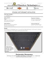
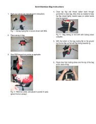
MAIN CLOSING INSTRUCTIONS<strong>BOC</strong> (<strong>HAND</strong> <strong>DEPLOY</strong> <strong>PILOT</strong> <strong>CHUTE</strong>) WITH LEFT OPEN <strong>BOC</strong> <strong>HAND</strong>LEPacking a Vector SE with the <strong>BOC</strong> (hand deployed pilot chute) is no different from the sportmodel. Please refer to the sport manual for closing instructions.RIPCORD (SPRING LOADED MAIN <strong>PILOT</strong> <strong>CHUTE</strong>)WITH LEFT SIDE MAIN ACTIVATIONNOTE:The Velcro on the centerflap is not used for thisapplication. Therefore it issmart to cover it with apiece of pile Velcro so itcannot come into contactwith anything.Lay bagged canopy in pack traywith the lines facing to the bottomof container as shown.19 | P age
After laying the deployment baginto the container (lines down)neatly tuck the risers down alongside of the reserve container andclose riser covers.NOTE:Make sure the risers lay ontop of the riser cover tuckpocket.Neatly figure 8 the entire bridleand lay it on the top of the bag.Thread a pull‐up cord onto the 2”closing loop as shown then pass itthrough the center of the pilotchute spring and out the grommetin the top.Center base of the pilot chute onthe bag and compress. Gather thepilot chute fabric around the base.Use the black ripcord cable to pinand hold in place.20 | P age
Thread the pull‐up cord thoughthe bottom flap and close.At this point pinning to hold inplace is not necessary if you’rekneeling on top of the pilot chuteand container.Thread the pull‐up cord thoughthe top flap and close.Thread the pull‐up cord thoughthe left then right side flaps andbefore closing, pass the ripcordcable through the left side mainactivation lanyard as shown.NOTE:Always close ripcord/right sideLAST!!!SEE IMPORTANT WARNING NEXT PAGE!21 | P age
WARNING:With a ripcord (spring loaded pilot chute) and left side main activation handle, donot close the left side flap last.The left side main activation lanyard can catch on the side flap.NOTE:Lanyards pull direction.22 | P age
MAIN CLOSING INSTRUCTIONS<strong>PILOT</strong> <strong>CHUTE</strong> ASSIST STATIC LINE (SPRING LOADED MAIN <strong>PILOT</strong> <strong>CHUTE</strong>)NOTE:The Velcro on the centerflap is not used for thisapplication. Therefore it issmart to cover it with apiece of pile Velcro so itcannot come into contactwith anything.Lay bagged canopy in pack traywith the lines facing to the bottomof container as shown.23 | P age
After laying the deployment baginto the container (lines down)neatly tuck the risers down alongside of the reserve container andclose riser covers.NOTE:Make sure the risers lay ontop Make of sure the riser the risers cover lay tuck onpocket. top of the riser cover tuckNeatly figure 8 the entire bridle andlay it on the top of the bag.Thread a pull‐up cord onto the 2”closing loop as shown then pass itthrough the center of the pilotchute spring and out the grommetin the end.Center base of the pilot chute onthe bag and compress. Gatheringthe pilot chute fabric around thebase.Use the black ripcord wire to pinand hold in place.24 | P age
NOTE:The type of aircraft used will determine what side the static line is routed. If the door ison the left side of the aircraft, the static line should be routed out the right side of thecontainer as show below. On a right door aircraft the static line should come out the left.Thread the pull‐up cord throughthe bottom flap first, then thetop/center flap second and closesimultaneously.NOTE:Pinning is not necessary atthis point if you stay on topof it.Thread the pull‐up cord throughthe right side flap and draw it tothe center.Thread the pull‐up cord throughthe left and last side flap.Close and pin as shown.SEE STOWING THE STATIC LINE ON PAGE 3125 | P age
MAIN CLOSING INSTRUCTIONS<strong>PILOT</strong> <strong>CHUTE</strong> ASSIST STATIC LINE (<strong>HAND</strong> <strong>DEPLOY</strong> <strong>PILOT</strong> <strong>CHUTE</strong>)NOTE:The Velcro on the centerflap is not used for thisapplication. Therefore it issmart to cover it with apiece of pile Velcro so itcannot come into contactwith anything.Lay bagged canopy in pack traywith the lines facing to the bottomof container as shown.26 | P age
After laying the deployment baginto the container (lines down)neatly tuck the risers down alongside of the reserve container andclose riser covers.NOTE:Make sure the risers lay ontop of the riser cover tuck.Neatly figure 8 the entire bridle andlay it on the top of the bag.Neatly S‐fold the pilot chute and layon the center of the main bag.27 | P age
NOTE:The type of aircraft used will determine what side the static line is routed. If the door ison the left side of the aircraft, the static line should be routed out the right side of thecontainer as show below. On a right door aircraft the static line should come out the left.Thread the pull‐up cord throughthe bottom flap first, then thetop/center flap second and closesimultaneously.Thread the pull‐up cord throughthe right side flap and draw it tothe center.Thread the pull‐up cord throughthe left and last side flap.Close and pin as shown.SEE STOWING THE STATICLINE ON PAGE 31.28 | P age
MAIN CLOSING INSTRUCTIONSDIRECT BAG STATIC LINENOTE:The Velcro on the centerflap is not used for thisapplication. Therefore it issmart to cover it with apiece of pile Velcro so itcannot come into contactwith anything.NOTE:The Canopies Pilot Chute Attachment(PCA) MUST BE DISCONECTED FROM THEINSIDE OF THE BAG. Please follow theinstructions on page 17 (ATTACHING THESTATIC LINE (DIRECT BAG <strong>DEPLOY</strong>MENT)Lay bagged canopy in pack traywith the lines facing to the bottomof container as shown.After laying the deployment baginto the container neatly tuck therisers down along side of thereserve container and close risercovers.NOTE:Make sure the risers lay ontop of the riser cover tuck.29 | P age
NOTE:The type of aircraft usedwill determine what sidethe static line is routed. Ifthe door is on the left sideof the aircraft, the staticline should be routed outthe right side of thecontainer as show below.On right door aircraft thestatic line should come outthe left.Thread the pull‐up cord throughthe bottom flap first, then thetop/center flap second and closesimultaneously.Thread the pull‐up cord throughthe right side flap and draw it tothe center.30 | P age
Thread the pull‐up cord throughthe left and last side flap.Close and pin as shown.STOWING THE STATIC LINEFor LEFT door aircraft where thestatic line comes out the top rightside, push the excess black cableunder the left side flap.Push the excess slack static lineunder the flap it comes out of.31 | P age
For RIGHT door aircraft where thestatic line comes out the top leftside, push the excess black cableinto the ripcord channel.Close the pin cover.Stow static line as shown.NOTE:Stow must be tight; doublewrapping the rubber bandsis strongly advised.Stow static line snap in appropriateside spandex pocket.32 | P age
ADJUSTABLE HARNESS NOMENCLATUREMain Attachment PointsRing CoversChest StrapElastic KeeperChest AdapterRelease HandleMain Lift Web(MLW)3 Bar Adjuster CoverLateral StrapFront of Leg Strap and PadElastic keeperFront of Leg AdapterRear of leg33 | P age
DONNING AND ADJUSTING THE VECTOR SE HARNESSDetermine fit. To the left is anexample of a good fit.The leg pads may be adjusted toaccommodate most all leg sizes andconfigurations.NOTE:It helps thefit by liftingthe rig frombehind asthe studenttightens theleg straps.If the container hangs low asshown below and chest strap sitshi, the MLW is most likely to long. Ifthe chest strap doesn’t sit hi andthe rig still hangs low, the studenthas a very short torso.NOTE:Correct threading of thechest strap.34 | P age
To shorten the MLW:Open the Velcro covers,rotate 3 bar adapter up thenpush the required length ofMLW through the 3 baradapter.←PullAs shown in the 4 photos tothe left, grip with your forefinger to hold in place andpull with your oppositehand.←PullTo Lengthen the MLW:Open the Velcro covers,rotate 3 bar adapter up thenpush out to the requiredlength of MLW through the3 bar adapter.←Pull35 | P age
Lay the 3 bar adapter back downand close the Velcro covers.NOTE:Make sure no hook Velcrois exposed and cannotcome into contact withother parts of the rig.Tuck the dead end onto its elastickeeper.Stow remaining excess strap intothe rear of leg pad cover.36 | P age
After tightening the leg straps,thread the excess through theelastic keeper on the rear of legstrap.The entire excess length of legstrap is pulled through.Fold/roll up excess and stow inkeeper as sown.NOTE:DONNING THE VECTOR SE FIXED HARNESSThe Vector SE fixed harness is no different from the sport model. Please refer to theVector 3 sport manual for donning instructions.37 | P age
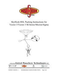
NOTES:FXC INSTALATION1. The Vector SE does not come setup standard for the FXC model 12000 Installation.It must be ordered specifically for FXC model 12000 use.2. Please refer to the FXC model 12000 manual and regularly check for any recentproduct service bulletins.3. Fitting an FXC to a Vector SE reserve container requires altering it from its originalform and should be done only by a Master <strong>Parachute</strong> Rigger or Equivalent.VECTOR SE MOUNTING INSTRUCTIONSMark the center of the #6 closingflap, using a straight edge as shownto the left.With the FXC Armed and in the offposition, insert the RLS pin into theFXC terminal ends.Lay the mounting bracket in placeand mark for the mounting holes.Mounting Bracket38 | P age
NOTE:After mounting the housing,the FXC marine eye terminalend should be able to justtouch the grommet asshown.Check this before punchingthe holes.CAREFULLY punch the 2 mountingholes using a ⅛” (3mm) punch.NOTE:Make sure nothing is in theway when punching.After punching the holes, centerand sew a piece of 1”x 2” Velcro tothe back side of the #6 closing flap.Then transfer the holes through theVelcro.Lightly searing the holes afterwordis optional.39 | P age
Insert power unit into the providedpocket located in the left sidereserve pack tray exactly as shown.Hand tack pocket closed usingsupper tack or equivalent.View of hand tack (close‐up).40 | P age
Bend the housing to align andmount the housing in place, usingthe FXC supplied housing mountingbrackets and screws.NOTE:Mounting base may needto be altered from itsoriginal form.View after mounting the housing.Stow the control unit housing underthe Velcro flap provided in the overshoulder area.NOTE:After mounting, coverthe 1”x 2” pile Velcrowith an equal length ofhook Velcro.41 | P age
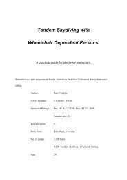
Stow the control unit housing underthe Velcro flap provided to the rightof the ring cover.Loosen the mounting clamp screwslocated on the back side of thecontrol unit. Slide clamp onto theprovided Type 17 strap and tightenscrews.FXC INSTALLATION IS COMPLETE.Please refer to the following pagefor assemble and packinginformation.42 | P age
Assembling and packing the reserve in a Vector SE with an FXC mounted is no different from thesport model without an FXC. Please refer to the Vector 3 sport manual for reserve assembling andpacking instructions and the following note.NOTE:Make sure the RSL pin passesthrough both marine eyeterminal ends when closingthe last reserve flap atpacking.ADDITIONAL MISCELLANEOUS OPTIONS:CARRY <strong>HAND</strong>LE (OPTIONAL)BELLY BAND (OPTIONAL)43 | P age
Notes:44 | P age
45 | P age