BERCO - MACHINE TOOL DIVISION - Assurich.com.my
BERCO - MACHINE TOOL DIVISION - Assurich.com.my
BERCO - MACHINE TOOL DIVISION - Assurich.com.my

Create successful ePaper yourself
Turn your PDF publications into a flip-book with our unique Google optimized e-Paper software.
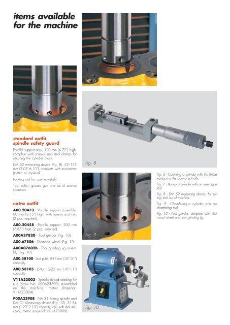
items availablefor the machineFig. 6Fig. 7standard outfitspindle safety guardParallel support assy, 120 mm (4.72”) high,<strong>com</strong>plete with screws, nuts and clamps forsecuring the cylinder block.DM 52 measuring device (Fig. 8), 52–155mm (2.05”-6.10”), <strong>com</strong>plete with micrometer(metric or imperial).Locking rod for counterweight.Tool puller, grease gun and set of servicespanners.extra outfitA00.20473 - Parallel support assembly,80 mm (3.15”) high, with screws and nuts(2 pcs. required).A00.20458 - Parallel support, 200 mm(7.87”) high (2 pcs. required).A00A27820 - Tool grinder (Fig. 10).A00.67506 - Diamond wheel (Fig. 10).A00A07602B - Tool grinding jig assembly(Fig. 10).A00.58100 - Stud puller, 8-13 mm (.32”-.51”)capacity.A00.58105 - Ditto, 12-25 mm (.47”-.1”)capacity.V11A23003 - Spindle infeed reading fixture(draw. No. A00A23700), assembledon the machine, metric (Imperial:V11A23004).P00A23908 - MA 31 Boring spindle andDM 31 Measuring device (Fig. 12), 31-54mm (1.20”-2.13”) capacity, cpl. with dial indicator,metric (Imperial: P01A23908).Fig. 8Fig. 9Fig. 10Fig. 6 - Centering a cylinder with the fixtureequipping the boring spindle.Fig. 7 - Boring a cylinder with an insert typetool.Fig. 8 - DM 52 measuring device, for settingtool out of machine.Fig. 9 - Chamfering a cylinder with thechamfering tool.Fig. 10 - Tool grinder, <strong>com</strong>plete with diamondwheel and tool grinding jig.