RTM 270/B - Berco S.p.A
RTM 270/B - Berco S.p.A
RTM 270/B - Berco S.p.A
- No tags were found...

Create successful ePaper yourself
Turn your PDF publications into a flip-book with our unique Google optimized e-Paper software.
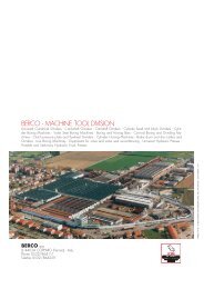
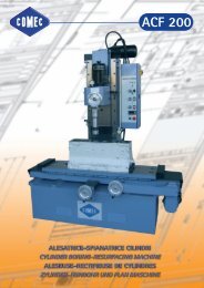
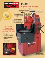
<strong>RTM</strong> <strong>270</strong>Crankshaft grinderA Companyof ThyssenKruppBERCO S.p.A.
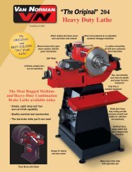
<strong>RTM</strong> <strong>270</strong>/B - 1300 - 1600 - 20001 Lever and knob foradjustment of the belts.2 Headstock spindle rotationcontrol lever, 3-position: start,neutral, braking.3 Faceplate lock pin controlknob.4 Table traverse handwheel.5 Lever for fast traversing thetable in either direction,equipped withelectromechanical safetydevice against unintentionalmaneuvers.6 One-shot pump for table feedgearing lubrication.7 Wheelhead micrometer feedcontrol unit, for plunge grinding.8 Pedal control to actuatefaceplate lock pins.9 Hydraulic wheel dresser:opening and shutoff of coolantas well as automatic return ofthe diamond slide areautomatic.10 Levers for shifting andlocking the tailstock quill.11 Signal light fixture forjournal lineup.12 Hydralic steady rest withmechanical lock, in workingposition.13 Wheelhead traverse controllever, 2-positions: fast return,slow and fast approach.14 Wheelhead infeed controlhandwheel.15 Centralized, low-tensionelectric controls box, with mainswitch which can be blockedvia a padlock.16 Hydraulic pedal control foractuating tailstock quillretraction.Figg. 2,3Diagrams showing, respectively,top roundness and surface finishdegree obtainable with the <strong>RTM</strong><strong>270</strong>.Fig. 2 Fig. 391011121231341451567816Fig. 1General view of the machine in the “B” execution, the most complete because of specific devices and automatics.
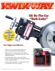
Fig. 4Workhead where the fo u rm ovements stand out in full re l i e f .Fig. 5Workhead equipped with 180 mm( 7 3 /3 2”) dia. selfcentering chuck.Fig. 6Workhead equipped with drivingcollar and center with ring nut.Fig. 4 Fig. 5 Fig. 6The <strong>Berco</strong> <strong>RTM</strong> <strong>270</strong> is acrankshaft grinder which hasbeen designed to meet themanifold requirements of thosepeople who must handle bothunit and production regrindingof small and medium runs ofcrankshafts.If view of this, the <strong>RTM</strong> <strong>270</strong>has been realized in threedifferent executions, each onehaving trhee different distancesbetween centers.Execution “A”It is the simplest execution andcan thus be regarded to as thebasic execution.No automatics are provided forin the standard outfit of thismachine, the machine beingsuitable only for regrinding ofcrankshafts with differentdimensions and specifications.Execution “B”It is the most completeexecution, being featured byspecific devices andautomatics which allowprofitable and timesavingregrinding of small andmedium runs of crankshafts.Execution “D”Essentially similar to the “A”execution, it is furthermoreequipped with a unit foractuating table traverse andreverse thus allowing cylindricalgrinding.The customer will thus be ableto choose, out of theseexecutions, the one whichbetter suits his specificrequirements and add theseveral optionals available inthe extra outfit.Other techincal and costructionfeatures of the <strong>RTM</strong> <strong>270</strong> areset forth hereunder:• Self-locking counterweights,radially adjustable andprotected by safety guards incompliance with the accidentprevention regulations.• Drive via high-resistance,high-flexible cogged belts, toassure an even and surgingfreerotation of workpiece.• Clutch located direct on themain spindle, to obtain fastand precise balancing of massin rotation.• Air-float headstock andtailstock.• Tailstock quill with 50 mm(1 31 /32”) travel, to make loadingand unloading of thecrankshafts easier and faster.• Workheads with fourmovements:- radial movement- cross movement- 360° rotary motion, with fastindexing for 2, 3, 4, 5 and 6cylinder engine crankshafts- micrometer swing movement.All versions can be suppliedalso with stepless variablespeed workhead motor.
Other executions of the machine<strong>RTM</strong> <strong>270</strong>/A - 1300 - 1600 - 2000In this execution, the machine is equipped with:• 2-pole motor for headstock spindle ro t a t i o n• h yd raulic system for slow and fast wheelheadt rave rs e• 4 - w ay cross slide swing heads• unit for fast trave rsing the table in eitherd i re ct i o nFig. 7G e n e ral view of the machine in the “A” exe c u t i o n .
<strong>RTM</strong> <strong>270</strong>/D - 1300 - 1600 - 2000Similar, as far as standard outfit is concerned, tothe “A” execution, this machine differs forhaving the possibility to regrind both crankshaftand cylindrical shafts.The table, in fact, besides fast traverse, isfeatured by work traverse, with automatic andmanual reversal of the feed direction.Travel of the tables is adjustable via trip limitstops and the traverse speed is steplesslyadjustable via the potentiometer mounted in theelectric controls box.Fig. 8G e n e ral view of the machine in the “D” execution.
Specific devices and automaticsEach execution of the <strong>RTM</strong> <strong>270</strong>is fe a t u red by its own specificd e v i ces and automatics; othersa re available on request ass c h e m a t i cally shown at right.Executionsdevices and automaticsABDH yd ralic wheel dre s s e rP/No. A00A17750Wheel dresserH yd raulic pedal control for actuating tailstock quillre t ra ct i o nH yd raulic pedal control for actuating the wo r k h e a dlocking pinsH yd ralic steady re s tD PA/L signal light fixture for journal lineupS t a n d a rd outfitE x t ra outfitNot provided fo rWheel dresser for hyd raulic steady re s tPlunge feed device for grinding fillets and diameterof cra n k s h a ft journals - P/No. A00A17725Unit for actuating the automatic table trave rs eand re ve rs e
Fig. 9 Fig. 10Fig. 9Rear view of tailstock showing thetailstock quill actuating cylinderand the actuator which controls theworkhead fa ceplate locking pin.Fig. 10H yd raulic wheel dre s s e r.Fig. 11Wheel dre s s e r.Wheel dresserA B DUnit for dressing the face andthe edges of the grindingwheel, with the possibility toadjust radius of the crankshaftjournal fillet. The dressingdiamond is supplied only onrequest.Hydraulic wheel dresserA B DIt is installed on the top ofwheelhead and allows fastdressing of the grinding wheelface with uniform movement,even if the crankshaft ismounted in the machine.The diamond slide speed isadjustable at will andmovement can be reversedautomatically.A handwheel with indexed ringallows the adjustment of thediamond cutting depth as wellas the compensation forreduction in grinding wheeldiameter after each dressing.A ratchet lever allows obtainingthe micrometer work jogging ofthe diamond holder, withconstant increments.Unless clearly required whenplacing the order, no diamondwill equip the wheel dresser.H yd raulic pedal control fo ra ctuating tailstock quillre t ra ct i o nThe device actuates, thro u g hthe hyd raulic cylinder in fig. 9the tailstock quill re t ra ct i o n .The pedal control (16 fig. 1)l e aves the operator free handsthus facilitating the cra n k s h a ftsetup.A built-in contriva n ce pre ve n t sthe tailstock quill from re t ra ct i o nwhen the grinding wheel is inworking position.H yd raulic pedal control fo ra ctuating the wo r k h e a dlocking pinsA B D A B DThis device allows, through theh yd raulic swinging act u a t o rss h own in fig. 9, the locking pinsto enter their seats in theworkheads in the positionswhich we re preset for ce n t e r i n gc ra n k s h a ft journals.It actuates the locking pins ofboth headstock and tailstock atthe same time through thepedal (8 fig. 1) located in thel ower part of machine bed, thusspeeding up ce n t e r i n g .Fig. 11
Specific devices and automaticsA B CFig. 12Fig. 13 Fig. 14H yd raulic steady re s tA B DIt is small-sized steady rest andcan pra ct i cally be used with allc ra n k s h a ft types.It is fitted with a device, linked tothe upper shoe, for checkingcentering of cra n k s h a ft journals.A p p roach to and return from thewo r k p i e ce are hyd raulic andc o n t rolled manually, bya ctuating a leve r.S a fety microswitches pre ve n tfast automatic trave rse of thetable when the hyd raulic steadyrest is in working position.Wheel dresser for hyd ra u l i csteady re s tA B DShape and dimensions of thisgrinding wheel fa ce and ra d i u sd resser have specifically beendesigned for use on the “B”execution of the machine.It is mounted on the table,opposite the hyd raulic steadyrest, leaving the cra n k s h a ft inthe machine. The dre s s i n gdiamond is supplied only onre q u e s t .D PA/L signal light fixture fo rjournal lineupA B DIt is mounted on the top of theh yd raulic steady rest and isf i tted with a stylus that, oncec o r re ct journal wheel lineup isobtained, switches on a signall i g h t .S t a n d a rd outfitE x t ra outfitNot provided fo r
Fig. 15 Fig. 16Plunge feed device fo rgrinding fillets and diameterof the journalsA B DThis hyd ra u l i ca l l y- o p e ra t e dd e v i ce allows to obtain thewheelhead work feed, withp reset speed and travel, fo rgrinding the fillets and diameterof cra n k s h a ft journals (fig. 13).Oleomechanical tabletraverse and reverse unitA B DThis unit, which gives themachine the features of acylindrical grinder, is mostprofitably used in enginerebuilding shops in as much asit is often necessary to grindparts other than crankshaftssuch as bars, rods, etc.It consists essentially of:- a d.c. motor with electronicspeed adjustment for theautomatic work feed of thetable (traverse speed isadjustable from 5 to 300mm/min -2”+11 13 /16” perminute)- an oleomechanical unit forreversing table traverse,either manual or automaticvia limit stops sliding onto ascale secured to the table.Fig. 12H yd raulic steady rest and DPA / Lsignal light fixture mounted on itst o p .Fig. 13Wheelhead work feed devicec o n t rols panel.a) Feed speed adjustment knob (fo rgrinding the cra n k s h a ft journals)with fast approach lever;b) Wheelhead travel adjustmentk n o b ;c) Knob for engaging anddisengaging the wheelheadautomatic fe e d .Fig. 14Wheel dresser for hyd rauulic steadyre s t .Fig. 15C y l i n d r i cal grinding on the Berc o<strong>RTM</strong> <strong>270</strong>, “D” exe c u t i o n .Fig. 16E l e ct ronic conve rter for theautomatic table work fe e d .
Standard outfitFig. 17Fig. 19Fig. 18• safety guard s• cooling system, complete withp ower pump and tank on theback of machine, withs t a n d a rd 1 /2” gas thread nozzle(fig. 19)• set of splash guard s• 1 grinding wheel, 710 mm(28”) dia. 25 mm (1”) thick,mounted on whelelhub• 1 dummy shaft wheelb a l a n c i n g• 1 wheelhub puller• 1 ove rsize motor pulley, fo rworm wheel• 1 truncated center fo rwo r k h e a d• 2 ce n t e rs with ring nuts fo rworkheads• 1 center puller• 2 180 mm (7 3 /3 2”) dia. selfcenteringchucks, with chucks p a n n e r• 2 driving dogs, 20 ÷ 60 mm( 3 1 /6 4” - 2 3 /8”) ca p a c i t y• 2 driving dogs 60 ÷ 115 mm( 2 3 /8” - 4 1 2 /3 2”) ca p a c i t y• 2 driving collars• 2 normal steady rests (fig. 17)• 2 auxiliary conterweights(fig. 18)• 1 tool kit complete (fig. 22),w i t h :- 1 center position checkinga tt a c h m e n t ,- 1 centering rod,- 2 dial gauges for ditt o• 1 square for centering rod(fig. 21)• 1 feeler gauge for thecentering rod (fig. 23)• DMI - attachment for takingc rank throw (fig. 20)• 7 adjustable wedges fo rmachine levelling• 1 grease gun• set of serv i ce spanners• kg 2 oil for wheelheadl u b r i f i ca t i o n .
Fig. 20 Fig. 21Fig. 22Fig. 23Fig. 17Normal steady rests onto the table.Fig. 18Workhead position checkinga ttachment. The cra n k s h a ft is heldb e t ween chucks. A u x i l i a ryc o u n t e rweights fitted to wo r k h e a dfa ce p l a t e .Fig. 19Coolant tank and power pump.Fig. 20“DMI” attachment for taking cra n kt h row .Fig. 21Centering rod mounted on square ,for centering cra n k s h a ft journals.The cra n k s h a ft is held betwe e nce n t e rs .Fig. 22Tool kit with attachment, ce n t e r i n grod and indica t o rs .Fig. 23Centering rod mounted via as u r fa ce gauge on the DMIa ttachment, for truing the ce n t e rs .All items in the standard outfita re common to the diffe re n texecutions of the machine.
Extra outfitFig. 24 Fig. 25 Fig. 26Fig. 27The items listed in the extraoutfit can be used with any ofthe three executions of themachine.• grinding wheels, 710 mm(28”) dia. 203 mm (8”) hole,t h i k n e s s e s :20 mm 5 1 /6 4” code U 8 1 2 1 4 0 0 4 032 mm 1 1 /4” code U 8 1 2 1 4 0 0 6 040 mm 1 9 /1 6” code U 8 0 6 1 4 0 0 3 050 mm 2 ” code U 8 1 1 1 4 0 0 0 063 mm 2 3 1 /6 4” code U 8 1 1 1 4 0 0 1 0• 1 /4” gas thread nozzle( for wheel thickness more than20 mm - 5 1 /6 4” )code A 0 1 . 2 6 7 0 3• 3 /4” gas thread nozzle(for wheel thickness morethan 25 mm - 1”)code A 0 1 . 2 6 7 0 4• DRFM attachment for dre s s i n gand chamfering wheel fa ceand for dressing and taperingwheels sides (fig. 27), lessd i a m o n dcode A 0 0 A 1 7 8 0 0• DRP center grindingattachment (fig. 24)code A 0 0 A 1 7 8 2 5• LU/DC normal steady rest withbuilt-in centering fixture(fig. 26), less dial gaugecode A 0 0 A 1 7 7 0 0• LU/S narrow steady rest fo rn a r row journalscode A 0 0 A 1 7 6 5 0• LU/S/DC narrow steady re s twith built-in centering fixture ,less dial gaugecode A 0 0 A 1 7 6 7 5• s e l f - centering chuck 180 mm( 7 3 /3 2”) dia. complete witht h ree sets of three jaws, max.external capacity 245 mm(9 4 1 /6 4” )code A 0 0 A 1 7 2 1 7• pair of collapsible way cove rs ,in re p l a cement of the standardc ove rscode V 0 5 A 1 7 0 0 2• magnetic coolant clarifier withtank in replacement of thestandard tank (fig. 25), forcooling systemcode V08A17010• g ravity filtering clarifier withtank, in re p l a cement of thes t a n d a rd coolant tankcode V 0 8 A 1 4 0 0 2• diamond for the wheeld re s s e rscode C 4 6 5 9 0 4 0 1 0• SFN2/B portable belt types u p e r f i n i s h e r. Please re fer tothe loose leaflet (fig. 31)• AES 500 static balance r(please re fer to the loosel e a f l e t )• AEM elect ronic sizing unit(fig. 30)• PSM 127 continuousm e a s u rement attachment(fig. 28)• unit for checking tailstockc ross trave rse (fig. 29)code V 1 1 A 1 7 0 0 2• pair of knobs with indexe dbushing, for shifting theworkheads ra d i a l l ycode V 0 4 A 1 7 0 0 2
Fig. 28Fig. 24Grinding a center with the DRPattachment.Fig. 25Cooling system with magneticcoolant clarifier and tank.Fig. 26Steady rest with built-in centeringfixture.Fig. 27DRFM attachment for dressing andchamfering wheel face and fordressing and tapering wheel sides.Fig. 28PSM 127 continuous measurementattachment.Fig. 29Unit for direct check of thetailstock cross traverse; the dialgauge is the one in the standardoutfit.Fig. 30AEM electronic sizing and controlunit. To be used in conjunctionwith <strong>Berco</strong> PSM 127.Fig. 31SFN/2B portable belt typesuperfinisher.Fig. 29Fig. 30Fig. 31
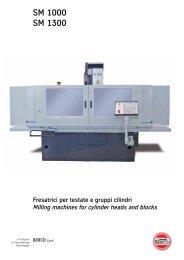
Technical dataWorking ca p a c i t yMax. diameter ground with full-size wheel m m 150 5 29 /32”Max. swing over table m m 540 21 1 /4”Min. diameter admitted in steady re s t s m m 30 1 11 /64”Max. diametera dmitted in steady re s t s m m 140 5 33 /64”Max. eccentricity of workheads (throw) m m 120 4 23 /32”Max. mass admitted between ce n t e rs kg 300 661 lbGeometric fe a t u re sHeight of center over table mm <strong>270</strong> 10 5 /8”Max. distance between ce n t e rs (2 exe c u t i o n s ) m m 1300 - 1600 - 1950 51” - 63” - 76 25 /32”Max. distance between chucks (2 exe c u t i o n s ) m m 1<strong>270</strong> - 1569 - 1919 50” - 61 25 /3 2” - 75 9 /16”S e l f - centering chuck diameter m m 180 7 3 /32”Max. grinding wheel diameter m m 710 28 ”Min. grinding wheel thickness m m 202 5/32”S t a n d a rd grinding wheel thickness m m 25 1 ”Max. grinding wheel thickness m m 63 2 31 /64”W h e e l h e a dTravel, fa s t m m 180 7 5 /64”Travel, fine m m 165 6 31 /64”Max. travel for plunge grinding m m 1 , 5 . 060 ”Feed per turn of the handwheel m m 1 . 040 ”H e a d s t o c kWo r k p i e ce rotation speed (6) r. p . m . 16 - 22 - 30 - 40 - 52 - 70* Wo r k p i e ce rotation speed (stepless va r i a b l e ) r. p . m . 12 ÷ 60Ta b l eM i c rometer feed per turn of the handwheel m m 5 , 84 . 23 ”Fast trave rse speed, per minute m / m i n 6 236” in/minS l ow trave rse speed, steplessly adjustable (only for D execution), per minute m / m i n 0,05 - 0,35 2 - 13 9 /1 6” in/minMotor ra t i n gW h e e l h e a d k W 4 (5,50 CV)H e a d s t o c k k W 0,45 ÷ 0,24 (0,6 ÷ 0,32 CV)* Headstock k W 0,24 ÷ 1,45 (0,32 ÷ 2 CV)Fast table trave rs e k W 0,55 (0,75 CV)S l ow table trave rse (only for D exe c u t i o n ) k W 0,62 (0,84 CV)H yd raulic sys t e m k W 0,55 (0,75 CV)Cooling sys t e m k W 0,15 (0,20 CV)Dimensions and massesLenght A (see fig. 32) m m 4500 - 5500 - 6219 177” - 216 17 /3 2” - 244 27 /32”Width B (see fig. 32) m m 1760 69 1 /8”Height C (see fig. 32) m m 1837 72 21 /64”A p p rox. mass, unpacked (exec. 1300) k g 3250 7150 l bA p p rox. mass, ocean packed (exec. 1300) k g 3820 8404 l bA p p rox. mass, unpacked (exec. 1600) k g 3400 7496 l bA p p rox. mass, ocean packed (exec. 1600) k g 4100 9039 l bA p p rox. mass, unpacked (exec. 1950) k g 3450 7606 l bA p p rox. mass, oce a n p a c ked (exec. 1950) k g 4150 9140 l bM e a s u rements, masses and executions can be changed without previous notice. Motor rating is re ffe red to 50 Hz fre q u e n c y.*Data valid for machines with stepless variable speed workhead motor.Fig. 32
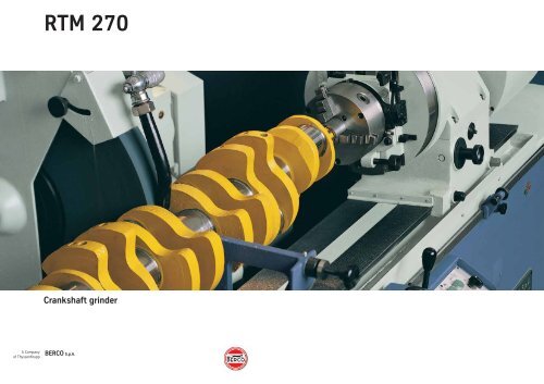
Others crankshaft grinders of the <strong>RTM</strong> seriesBesides the <strong>RTM</strong> <strong>270</strong> <strong>Berco</strong> ismanufacturing other crankshaftgrinder models; their mainspecifications are set forthhereunder:<strong>RTM</strong> 351Center height over table350 mm (13 3 /4” ) .Max. swing over table 700 mm( 2 7 9 /1 6” ) .Max. distance between ce n t e rs2400-3000 mm( 9 4 3 1 /6 4” - 118 7 /6 4” ) .Max. mass admitted betwe e nce n t e rs 800 kg (1760 lb).<strong>RTM</strong> 425ACenter height over table425 mm (16 3 /4” ) .Max. swing over table 850 mm( 3 3 1 /2” ) .Max. distance between ce n t e rs4020 mm (158 1 /6 4” ) .Max. mass admitted betwe e nce n t e rs 1200 kg (2645 lb).<strong>RTM</strong> 575Center height over table575 mm (22 5 /8” ) .Max. swing over table1150 mm (45 9 /3 2” ) .Max. distance between ce n t e rs4020 mm (158 1 /6 4” ) .Max. mass admitted betwe e nce n t e rs 1200 kg (2645 lb).<strong>RTM</strong> 700Center height over table700 mm (27 9 /1 6” ) .Max. swing over tablea1400 mm (55 1 /8” ) .Max. distance between ce n t e rs5700-6900 and 8000 mm( 2 2 4 1 3 /3 2” - 271 2 1 /3 2” e 315”).Max. mass admitted betwe e nce n t e rs 6000 kg (13200 lb).R T M 3 5 1R T M 5 7 5
00910.WM101GB00AISO 9001 Cert. n. 0029/5ISO 14001 Cert. n. 0009A/3Published by <strong>Berco</strong> Communications Dept.BERCO S.p.A.Via 1° Maggio, 23744034 Copparo (Ferrara) ItalyPhone (+39) 0532 864111Fax (+39) 0532 864259www.berco.commachinetools@berco.com