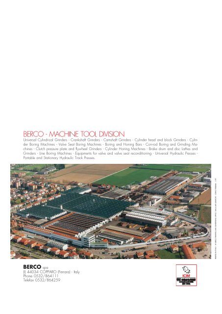
BERCO - MACHINE TOOL DIVISION - Assurich.com.my
BERCO - MACHINE TOOL DIVISION - Assurich.com.my
BERCO - MACHINE TOOL DIVISION - Assurich.com.my

You also want an ePaper? Increase the reach of your titles
YUMPU automatically turns print PDFs into web optimized ePapers that Google loves.
AC 650
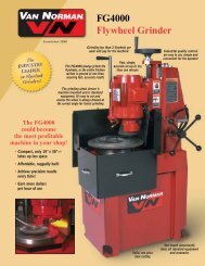
Fig. 17cylinder head fixtures(AC 650M)A01.32433 - Swinging fixture for holdingcylinder heads and V-blocks.A00.32470 - Fiat 128/Fiat Ritmo cylinderhead setup fixture.A00.41731A - Universal setup square,with variable angle top, for cylinder heads(Fig. 17).A00.41745 - Special fixture for Fiat 132cylinder heads, <strong>com</strong>plete with clamps andpins.A00A02600 - Parallel support for cylinderheads, <strong>com</strong>plete with plate and lockscrews (2pcs. required).A00.41749 - Clamp with lock screws forA00A02600 parallel supports (4 pcs. required).A00A02655 - Setup fixture for Fiat127/1050 and Fiat Ritmo-1050 cylinderheads.A00A02660 - Setup fixture for VW-Golfcylinder heads.A00A02668 - Setup fixture for Fiat Ritmodiesel and Fiat Regata diesel cylinderheads.Fig. 18Fig. 17 - Milling the surface of the exhaustmanifolds of a cylinder head mounted onthe swinging fixture. The small milling cutteris mounted in the universal adaptor.Fig. 18 - Quick clamping fixture for in-lineblock mounted on parallel supports.Fig. 19 - PCV Universal V-block fixture. Photoshows the 45° setup square.Fig. 20 - Fixture for boring 90° and 60°V-blocks.Fig. 19All the setup fixtures are extra outfit.Fig. 20
items availablefor the machineFig. 6Fig. 7standard outfitspindle safety guardParallel support assy, 120 mm (4.72”) high,<strong>com</strong>plete with screws, nuts and clamps forsecuring the cylinder block.DM 52 measuring device (Fig. 8), 52–155mm (2.05”-6.10”), <strong>com</strong>plete with micrometer(metric or imperial).Locking rod for counterweight.Tool puller, grease gun and set of servicespanners.extra outfitA00.20473 - Parallel support assembly,80 mm (3.15”) high, with screws and nuts(2 pcs. required).A00.20458 - Parallel support, 200 mm(7.87”) high (2 pcs. required).A00A27820 - Tool grinder (Fig. 10).A00.67506 - Diamond wheel (Fig. 10).A00A07602B - Tool grinding jig assembly(Fig. 10).A00.58100 - Stud puller, 8-13 mm (.32”-.51”)capacity.A00.58105 - Ditto, 12-25 mm (.47”-.1”)capacity.V11A23003 - Spindle infeed reading fixture(draw. No. A00A23700), assembledon the machine, metric (Imperial:V11A23004).P00A23908 - MA 31 Boring spindle andDM 31 Measuring device (Fig. 12), 31-54mm (1.20”-2.13”) capacity, cpl. with dial indicator,metric (Imperial: P01A23908).Fig. 8Fig. 9Fig. 10Fig. 6 - Centering a cylinder with the fixtureequipping the boring spindle.Fig. 7 - Boring a cylinder with an insert typetool.Fig. 8 - DM 52 measuring device, for settingtool out of machine.Fig. 9 - Chamfering a cylinder with thechamfering tool.Fig. 10 - Tool grinder, <strong>com</strong>plete with diamondwheel and tool grinding jig.
Fig. 11 - Toolhead with radial tool feed. Quitenecessary for facing, milling and boring ofcounterbores.Fig. 11AU MA 60 MA 52MA 31TR113ø 20 – 300BRø 109ø 300No. 3 Morse taperFRMax. 623275172,5 102,5ø 60 – 155ø 86ø 59Max. 548350213,5 136,5ø 32 – 125ø 86 ø 70ø 35ø 51Max. 648 25012612429,5ø 31 – 54ø 30898MAASPINDLES AND ACCESSORIESSPINDLES<strong>TOOL</strong>S FOR CAST IRONTypeToolholderMA31 –capacitydia. mmbrazedtipBORING SPOT-FACING DEAD-END HOLE CHAMFERINGinsertholderinserttypecapacitydia. mmbrazedtipinsertholderinserttypecapacitydia. mmbrazedtipinsertholder31 – 42 U20226530131 – 42A03.19396U202265301 A03.193961.22” - 1.65” *1.22” - 1.65”44 – 54U003101000U003101000U202248071 A04.19362 U0031010001.73” - 2.13”40 – 54 U20226533140 – 54A03.19399U202265331 A03.193991.57” - 2.13” *1.57” - 2.13”inserttypecapacitydia. mmbrazedtipMA52A00A23668A00A2366952 – 622.05” - 2.44”60 – 922.36” - 3.62”U202267051*A00A2367656 – 662.21” - 2.60”U202265351 A00A0789164 – 102U0101010602.52” - 4.02”65 – 772.56” - 3.03”U202248101 A00A2367875 – 107U0031010002.95” - 4.21”54 – 662.13” - 2.60”U20226909164 – 98U0031010002.52” - 3.86”A00A2367090 – 1253.54” - 4.92”U202267061*A00A07882100 – 135U202265361 A00A078943.94” - 5.32”105 – 139U202248121 A00A236804.13” - 5.47”96 – 1303.78” - 5.12”U202269101A00A2366960 – 922.36” - 3.62”U202267051*A00A2367664 – 102U202265351 A00A078912.52” - 4.02”75 – 107U202248101 A00A236782.95” - 4.21”64 – 982.52” - 3.86”U202269091MA60 A00A23670A00A2377190 – 1253.54” - 4.92”123 – 1554.84” - 6.10”U202267061*100 – 135105 – 13996 – 130U010101060U003101000U0031010003.94” - 5.32”4.13” - 5.47”3.78” - 5.12”A00A07882U202265361 A00A07894U202248121 A00A23680U202269101133 – 165137 – 165128 – 1655.24” - 6.50”5.39” - 6.50”5.04” - 6.50”* Tools supplied as standard outfit of the relevant spindles Tools for steel on requestACCESSORIESAUA00A23800Universal adaptor for milling cutter and step-down bushMAAA00A23903Drill chuck, capacity dia. mm 1 – 13 ( 3 /64” - 33 /64”)BRA00A23902Step-down bush with No. 3 Morse taperTRA00A23840Toolhead with radial feed tool, cpl. with tool No. U202265422 for cast ironFRA00A23820300 mm (11.8”) dia. milling cutter with 8 multiedged insert No. U003355020 for cast iron and aluminium (only for AC 650M)All of the spindles and accessories are extra outfit.
technicaldataBADCworking capacity AC 650 AC 650Mboring capacitymm31–155 1.22”-6.10”31–155 1.22”-6.10”max. boring depthmm350 13.78”350 13.78”max. milling widthmm298 11.73”max. milling areamm200x750 7.87”x29.53”geometric featuresmax. spindle head travel (D)distance spindle C/L tocolumn waysuseful table surfacemax. table traversemmmmmmmm530 20.87” 530 20.87”335 13.20” 335 13.20”400x1000 15.75”x39.37” 400x1000 15.75”x39.37”830 32.68” 830 32.68”max. table cross traversemm70 2.76” 70 2.76”Fig. 5Fig. 5 - Boring a machine tool <strong>com</strong>ponentwith a dead-end hole tool.speedsspindle rotation speeds (6)spindle head workfeed speed (3), per revolutionspindle head fast feed, up anddown, per minute (1)table workfeed speeds (2), per minutemotor ratingr.p.m.mmmmmm105 210 280390 550 780105 210 280390 550 7800.06 0.12 0.18 0.06 0.12 0.18(.0024” .0047” .0071”) (.0024” .0047” .0071”)1200 47.24” 1200 47.24”52 104 2.05” 4.10”spindle head work feed andspindle rotationfast spindle head traverse,up and downtable traversetool grinderdimensions and weightskWkWkWkW1.2/0.9 (1.6/1.2 HP) 1.2/0.9 (1.6/1.2 HP)0.060 (0.080 HP) 0.060 (0.080 HP)0.072 (0.094 HP)0.190 (0.250 HP) 0.190 (0.250 HP)length (A)mm2570 101”2570 101”width (B)mm1175 46.25”1175 46.25”heigth (C)mm1920 75.59”1920 75.59”approx. weight, unpackedkg1240 2731 lb1250 2753 lbMeasurements, weights and executions are notbinding on the manufacturers.Motor rating is referred to 50 Hz frequency.approx. weight, ocean packedkg1540 3392 lb1550 3414 lb