262726-1 VER:02/11 WIRING DEVICES SECTION 262726 ...
262726-1 VER:02/11 WIRING DEVICES SECTION 262726 ...
262726-1 VER:02/11 WIRING DEVICES SECTION 262726 ...

You also want an ePaper? Increase the reach of your titles
YUMPU automatically turns print PDFs into web optimized ePapers that Google loves.
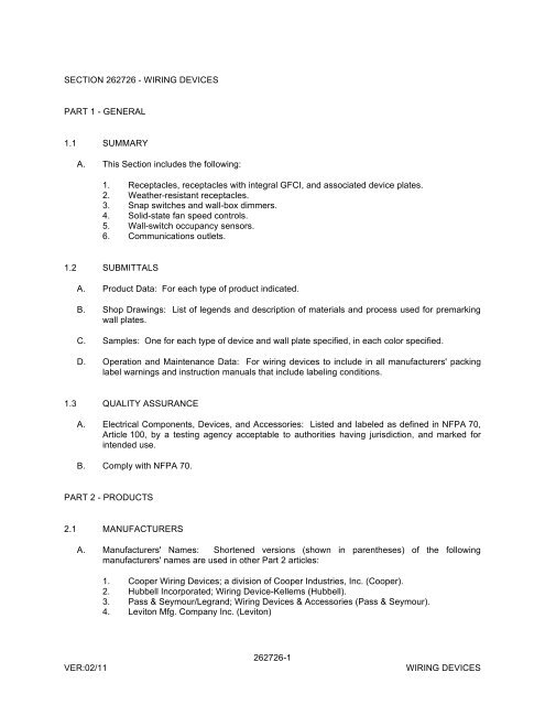
<strong>SECTION</strong> <strong>262726</strong> - <strong>WIRING</strong> <strong>DEVICES</strong>PART 1 - GENERAL1.1 SUMMARYA. This Section includes the following:1. Receptacles, receptacles with integral GFCI, and associated device plates.2. Weather-resistant receptacles.3. Snap switches and wall-box dimmers.4. Solid-state fan speed controls.5. Wall-switch occupancy sensors.6. Communications outlets.1.2 SUBMITTALSA. Product Data: For each type of product indicated.B. Shop Drawings: List of legends and description of materials and process used for premarkingwall plates.C. Samples: One for each type of device and wall plate specified, in each color specified.D. Operation and Maintenance Data: For wiring devices to include in all manufacturers' packinglabel warnings and instruction manuals that include labeling conditions.1.3 QUALITY ASSURANCEA. Electrical Components, Devices, and Accessories: Listed and labeled as defined in NFPA 70,Article 100, by a testing agency acceptable to authorities having jurisdiction, and marked forintended use.B. Comply with NFPA 70.PART 2 - PRODUCTS2.1 MANUFACTURERSA. Manufacturers' Names: Shortened versions (shown in parentheses) of the followingmanufacturers' names are used in other Part 2 articles:1. Cooper Wiring Devices; a division of Cooper Industries, Inc. (Cooper).2. Hubbell Incorporated; Wiring Device-Kellems (Hubbell).3. Pass & Seymour/Legrand; Wiring Devices & Accessories (Pass & Seymour).4. Leviton Mfg. Company Inc. (Leviton)<strong>VER</strong>:<strong>02</strong>/<strong>11</strong><strong>262726</strong>-1<strong>WIRING</strong> <strong>DEVICES</strong>
2.6 FAN SPEED CONTROLSA. Modular, 120-V, full-wave, solid-state units with integral, quiet on-off switches and audiblefrequency and EMI/RFI filters. Comply with UL 1917.1. Continuously adjustable [slider] [toggle switch] [rotary knob], [5 A] [1.5 A].2. Three-speed adjustable [slider] [rotary knob], 1.5 A.2.7 OCCUPANCY SENSORSA. Wall-Switch Sensors:1. Products: Subject to compliance with requirements, provide one of the following:a. Leviton; 091-ODS15-IDI2. Description: Passive-infrared type, 120/277 V, adjustable time delay up to 30 minutes,180-degree field of view, with a minimum coverage area of 900 sq. ft..2.8 WALL PLATESA. Single and combination types to match corresponding wiring devices.1. Plate-Securing Screws: Metal with head color to match plate finish.2. Material for Finished Spaces: [Smooth, high-impact thermoplastic] [0.035-inch- thick,satin-finished stainless steel].3. Material for Unfinished Spaces: Smooth, high-impact thermoplastic.4. Material for Damp Locations: Thermoplastic with spring-loaded lift cover, and listed andlabeled for use in "wet locations."B. Wet-Location, Weatherproof Cover Plates: NEMA 250, complying with type 3R weatherresistant[die-cast aluminum,] [thermoplastic] with lockable cover.2.9 FLOOR SERVICE FITTINGSA. Type: Modular, [flush-type] [flap-type] [above-floor], dual-service units suitable for wiringmethod used.B. Compartments: Barrier separates power from voice and data communication cabling.C. Service Plate: [Rectangular] [Round], [die-cast aluminum] [solid brass] with satin finish.D. Power Receptacle: NEMA WD 6 configuration 5-20R, gray finish, unless otherwise indicated.E. Voice and Data Communication Outlet: [Blank cover with bushed cable opening] [Twomodular, keyed, color-coded, RJ-45 Category 5e jacks for UTP cable].<strong>VER</strong>:<strong>02</strong>/<strong>11</strong><strong>262726</strong>-4<strong>WIRING</strong> <strong>DEVICES</strong>
2.10 FINISHESA. Color: Wiring device catalog numbers in Section Text do not designate device color.1. Wiring Devices Connected to Normal Power System: Ivory or as selected by Architectunless otherwise indicated or required by NFPA 70 or device listing.2. Wiring Devices Connected to Emergency Power System: Red.3. TVSS Devices: Blue.PART 3 - EXECUTION3.1 INSTALLATIONA. Comply with NECA 1, including the mounting heights listed in that standard, unless otherwisenoted.B. Coordination with Other Trades:1. Take steps to insure that devices and their boxes are protected. Do not place wall finishmaterials over device boxes and do not cut holes for boxes with routers that are guidedby riding against outside of the boxes.2. Keep outlet boxes free of plaster, drywall joint compound, mortar, cement, concrete, dust,paint, and other material that may contaminate the raceway system, conductors, andcables.3. Install device boxes in brick or block walls so that the cover plate does not cross a jointunless the joint is troweled flush with the face of the wall.4. Install wiring devices after all wall preparation, including painting, is complete.C. Conductors:1. Do not strip insulation from conductors until just before they are spliced or terminated ondevices.2. Strip insulation evenly around the conductor using tools designed for the purpose. Avoidscoring or nicking of solid wire or cutting strands from stranded wire.3. The length of free conductors at outlets for devices shall meet provisions of NFPA 70,Article 300, without pigtails.4. Existing Conductors:a. Cut back and pigtail, or replace all damaged conductors.b. Straighten conductors that remain and remove corrosion and foreign matter.c. Pigtailing existing conductors is permitted provided the outlet box is large enough.D. Device Installation:1. Replace all devices that have been in temporary use during construction or that showsigns that they were installed before building finishing operations were complete.2. Keep each wiring device in its package or otherwise protected until it is time to connectconductors.3. Do not remove surface protection, such as plastic film and smudge covers, until the lastpossible moment.4. Connect devices to branch circuits using pigtails that are not less than 6 inches in length.<strong>VER</strong>:<strong>02</strong>/<strong>11</strong><strong>262726</strong>-5<strong>WIRING</strong> <strong>DEVICES</strong>
5. When there is a choice, use side wiring with binding-head screw terminals. Wrap solidconductor tightly clockwise, 2/3 to 3/4 of the way around terminal screw.6. Use a torque screwdriver when a torque is recommended or required by themanufacturer.7. When conductors larger than No. 12 AWG are installed on 15- or 20-A circuits, spliceNo. 12 AWG pigtails for device connections.8. Tighten unused terminal screws on the device.9. When mounting into metal boxes, remove the fiber or plastic washers used to hold devicemounting screws in yokes, allowing metal-to-metal contact.E. Receptacle Orientation:1. Install ground pin of vertically mounted receptacles [up] [down], and on horizontallymounted receptacles to the [right] [left].F. Device Plates: Do not use oversized or extra-deep plates. Repair wall finishes and remountoutlet boxes when standard device plates do not fit flush or do not cover rough wall opening.G. Dimmers:1. Install dimmers within terms of their listing.2. Verify that dimmers used for fan speed control are listed for that application.3. Install unshared neutral conductors on line and load side of dimmers according tomanufacturers' device listing conditions in the written instructions.H. Arrangement of Devices: Unless otherwise indicated, mount flush, with long dimension verticaland with grounding terminal of receptacles on top. Group adjacent switches under single,multigang wall plates.3.2 IDENTIFICATIONA. Comply with Division 16 Section "Electrical Identification."1. Receptacles: Identify panelboard and circuit number from which served. Use hot,stamped or engraved machine printing with [black] [white] [red]-filled lettering on face ofplate, and durable wire markers or tags inside outlet boxes.3.3 FIELD QUALITY CONTROLA. Perform tests and inspections and prepare test reports.1. Test Instruments: Use instruments that comply with UL 1436.2. Test Instrument for Convenience Receptacles: Digital wiring analyzer with digital readoutor illuminated LED indicators of measurement.B. Tests for Convenience Receptacles:1. Line Voltage: Acceptable range is 105 to 132 V.2. Percent Voltage Drop under 15-A Load: A value of 6 percent or higher is not acceptable.3. Ground Impedance: Values of up to 2 ohms are acceptable.4. GFCI Trip: Test for tripping values specified in UL 1436 and UL 943.<strong>VER</strong>:<strong>02</strong>/<strong>11</strong><strong>262726</strong>-6<strong>WIRING</strong> <strong>DEVICES</strong>