SECTION 260553 - IDENTIFICATION FOR ELECTRICAL SYSTEMS
SECTION 260553 - IDENTIFICATION FOR ELECTRICAL SYSTEMS
SECTION 260553 - IDENTIFICATION FOR ELECTRICAL SYSTEMS

You also want an ePaper? Increase the reach of your titles
YUMPU automatically turns print PDFs into web optimized ePapers that Google loves.
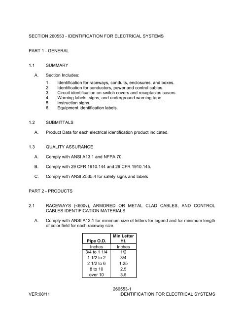
<strong>SECTION</strong> <strong>260553</strong> - <strong>IDENTIFICATION</strong> <strong>FOR</strong> <strong>ELECTRICAL</strong> <strong>SYSTEMS</strong>PART 1 - GENERAL1.1 SUMMARYA. Section Includes:1. Identification for raceways, conduits, enclosures, and boxes.2. Identification for conductors, power and control cables.3. Circuit identification on switch covers and receptacles covers4. Warning labels, signs, and underground warning tape.5. Instruction signs.6. Equipment identification labels.1.2 SUBMITTALSA. Product Data for each electrical identification product indicated.1.3 QUALITY ASSURANCEA. Comply with ANSI A13.1 and NFPA 70.B. Comply with 29 CFR 1910.144 and 29 CFR 1910.145.C. Comply with ANSI Z535.4 for safety signs and labelsPART 2 - PRODUCTS2.1 RACEWAYS (
B. Colors:1. Black letters on a white field.2. Legend: Indicate voltage and circuit or service.C. Self-Adhesive Vinyl Labels: Preprinted, flexible label laminated with a clear, weatherandchemical-resistant coating and matching wraparound adhesive tape for securingends of legend label.D. Snap-Around Labels: Slit, pretensioned, flexible, preprinted, color-coded acrylicsleeve, with diameter sized to suit diameter of raceway or cable it identifies and to stayin place by gripping action.E. Snap-Around, Color-Coding: Slit, pretensioned, flexible, solid-colored acrylic sleeve, 2inches long, with diameter sized to suit diameter of raceway or cable it identifies and tostay in place by gripping action.2.2 CONDUCTOR <strong>IDENTIFICATION</strong> MATERIALSA. Marker Tapes: Vinyl or vinyl-cloth, self-adhesive wraparound type, with circuitidentification machine printed by thermal transfer or equivalent process.2.3 FLOOR MARKING TAPEA. 2-inch wide, 5-mil pressure-sensitive vinyl tape, with black and white stripes and clearvinyl overlay.2.4 UNDERGROUND-LINE WARNING TAPEA. Tape:1. Recommended by manufacturer for the method of installation and suitable toidentify and locate underground electrical and communications utility lines.2. Printing on tape shall be permanent and shall not be damaged by burialoperations.3. Tape material and ink shall be chemically inert, and not subject to degradingwhen exposed to acids, alkalis, and other destructive substances commonlyfound in soils.B. Color and Printing:1. Comply with ANSI Z535.1 through ANSI Z535.5.2. Inscriptions for Red-Colored Tapes: ELECTRIC LINE, HIGH VOLTAGE.3. Inscriptions for Orange-Colored Tapes: TELEPHONE CABLE, CATV CABLE,COMMUNICATIONS CABLE, OPTICAL FIBER CABLE.VER:08/11<strong>260553</strong>-2<strong>IDENTIFICATION</strong> <strong>FOR</strong> <strong>ELECTRICAL</strong> <strong>SYSTEMS</strong>
2.5 WARNING LABELS AND SIGNSA. Comply with NFPA 70 and 29 CFR 1910.145.B. Self-Adhesive Warning Labels: Factory-printed, multicolor, pressure-sensitiveadhesive labels, configured for display on front cover, door, or other access toequipment unless otherwise indicated.C. Baked-Enamel Warning Signs:1. Preprinted aluminum signs, punched or drilled for fasteners, with colors, legend,and size required for application.2. 1/4-inch grommets in corners for mounting.3. Nominal size, 7 by 10 inches.D. Warning label and sign shall include, but are not limited to, the following legends:1. Multiple Power Source Warning: "DANGER - <strong>ELECTRICAL</strong> SHOCK HAZARD -EQUIPMENT HAS MULTIPLE POWER SOURCES."2. Workspace Clearance Warning: "WARNING - OSHA REGULATION - AREA INFRONT OF <strong>ELECTRICAL</strong> EQUIPMENT MUST BE KEPT CLEAR <strong>FOR</strong> 36INCHES"2.6 INSTRUCTION SIGNSA. Engraved, laminated acrylic or melamine plastic, minimum 1/16 inch thick.1. Engraved legend with white letters on black face.2. Punched or drilled for mechanical fasteners.3. Framed with mitered acrylic molding and arranged for attachment at applicableequipment.B. Adhesive Film Label: Machine printed, in black, by thermal transfer or equivalentprocess. Minimum letter height shall be 1/2 inch.C. Adhesive Film Label with Clear Protective Overlay: Machine printed, in black, bythermal transfer or equivalent process. Minimum letter height shall be 1/2 inch.Overlay shall provide a weatherproof and UV-resistant seal for label.2.7 EQUIPMENT <strong>IDENTIFICATION</strong> LABELSA. Adhesive Film Label with Clear or White Background: Machine printed, black letters,by thermal transfer or equivalent process. Minimum letter height shall be 1/2 inch.Overlay shall provide a weatherproof and UV-resistant seal for label.B. Self-Adhesive, Engraved, Laminated Acrylic or Melamine Label: Adhesive backed,with white letters on a black background. Minimum letter height shall be 1/2 inch.VER:08/11<strong>260553</strong>-3<strong>IDENTIFICATION</strong> <strong>FOR</strong> <strong>ELECTRICAL</strong> <strong>SYSTEMS</strong>
PART 3 - EXECUTION3.1 INSTALLATIONA. Location: Install identification materials and devices at locations for most convenientviewing without interference with operation and maintenance of equipment.B. Apply identification devices to surfaces that require finish after completing finish work.C. Self-Adhesive Identification Products: Clean surfaces before application, usingmaterials and methods recommended by manufacturer of identification device.D. Attach signs and plastic labels that are not self-adhesive type with mechanical fastnersappropriate to the location and substrate.E. System Identification Color-Coding Bands for Raceways and Cables: Each colorcodingband shall completely encircle cable or conduit. Place adjacent bands of twocolormarkings in contact, side by side. Locate bands at changes in direction, atpenetrations of walls and floors, at 50-foot maximum intervals in straight runs, and at25-foot maximum intervals in congested areas.F. Underground-Line Warning Tape: During backfilling of trenches install continuousunderground-line warning tape directly above line at 6 to 8 inches below finishedgrade. Use multiple tapes where width of multiple lines installed in a common trenchexceeds 16 inches overall.G. Painted Identification: Comply with requirements in Division 09 painting Sections forsurface preparation and paint application.3.2 <strong>IDENTIFICATION</strong> SCHEDULEA. Accessible Raceways and Metal-Clad Cables, 600 V or Less, for Service, Feeder, andBranch Circuits More Than 20A, and 120V to ground: Label each end.B. Accessible Raceways and Cables within Buildings: On the covers of each junction andpull box of the following systems mark with self-adhesive vinyl labels or permanentblack marker. Write the circuit ID, system voltage and wiring system legend. Systemlegends shall be as follows:1. Emergency Power.2. UPS.3. Power (for normal power mark circuit ID and system voltage only)C. Power-Circuit Conductor Identification, 600 V or Less: For conductors in vaults, pulland junction boxes, manholes, and handholes, use color-coding conductor tape toidentify the phase.1. Color-Coding for Phase and Voltage Level Identification, 600 V or Less: Usecolors listed below for ungrounded service, feeder, and branch-circuitconductors.VER:08/11<strong>260553</strong>-4<strong>IDENTIFICATION</strong> <strong>FOR</strong> <strong>ELECTRICAL</strong> <strong>SYSTEMS</strong>
a. Color shall be factory applied.b. Colors for 208/120-V Circuits:1) Phase A: Black.2) Phase B: Red.3) Phase C: Blue.4) Neutral: White5) Ground: Greenc. Colors for 480/277-V Circuits:1) Phase A: Brown.2) Phase B: Orange.3) Phase C: Yellow.4) Neutral: Gray5) Ground: Greend. Field-Applied, Color-Coding Conductor Tape: Apply in half-lapped turns fora minimum distance of 6 inches (150 mm) from terminal points and inboxes where splices or taps are made. Apply last two turns of tape with notension to prevent possible unwinding. Locate bands to avoid obscuringfactory cable markings.D. Install instructional sign including the color code for grounded and ungroundedconductors using adhesive-film-type labels.E. Conductors to Be Extended in the Future: Attach write-on tags or marker tape toconductors and list source.F. Auxiliary Electrical Systems Conductor Identification: Identify field-installed alarm,control, and signal connections.1. Identify conductors, cables, and terminals in enclosures and at junctions,terminals, and pull points. Identify by system and circuit designation.2. Use system of marker tape designations that is uniform and consistent withsystem used by manufacturer for factory-installed connections.3. Coordinate identification with Project Drawings, manufacturer's wiring diagrams,and the Operation and Maintenance Manual.G. Locations of Underground Lines: Identify with underground-line warning tape forpower, lighting, communication, and control wiring and optical fiber cable.1. Install underground-line warning tape for both direct-buried cables and cables inraceway.H. Workspace Indication: Install floor marking tape to show working clearances in thedirection of access to live parts. Workspace shall be as required by NFPA 70 and29 CFR 1926.403 unless otherwise indicated. Do not install at flush-mountedpanelboards and similar equipment in finished spaces.I. Warning Labels for Indoor Cabinets, Boxes, and Enclosures. Self-adhesive warninglabels or Acrylic or Melamine warning signs.1. Identify system voltage with white letters on a black background2. Apply to exterior of door, cover, or other access.<strong>260553</strong>-5VER:08/11<strong>IDENTIFICATION</strong> <strong>FOR</strong> <strong>ELECTRICAL</strong> <strong>SYSTEMS</strong>
3. For equipment with multiple power or control sources, apply to door or cover ofequipment including, but not limited to, the following:a. Power transfer switches.b. Controls with external control power connections.J. Warning Labels for Outdoor Cabinets, Boxes, Enclosures, and Equipment: Acrylic orMelamine only.1. Identify system voltage with white letters on a black background2. Apply to exterior of door, cover, or other access.3. For equipment with multiple power or control sources, apply to door or cover ofequipment including, but not limited to, the following:a. Power transfer switches.b. Controls with external control power connections.K. Switch and Receptacle Covers: Black letter on a white or clear self-adhesive labelmachine tape. Minimum 3/8-inch high letters.L. Operating Instruction Signs: Install instruction signs to facilitate proper operation andmaintenance of electrical systems and items to which they connect. Install instructionsigns with approved legend where instructions are needed for system or equipmentoperation.M. Emergency Operating Instruction Signs: Install instruction signs with white legend on ared background with minimum 1/2-inch high letters for emergency instructions atequipment used for power transfer, load shedding or other emergency operation.N. Equipment Identification Labels: On each unit of equipment, install unique designationlabel that is consistent with wiring diagrams and/or schedules. (e.g. CU-1) Apply labelsto disconnect switches and protection equipment, central or master units, controlpanels, control stations, terminal cabinets, and racks of each system. Systems includepower, lighting, control, communication, signal, monitoring, and alarm systems unlessequipment has its own identification.1. Labeling Instructions:a. Indoor Equipment: Adhesive film label, Adhesive film label with clearprotective overlay, or Self-adhesive, engraved, laminated acrylic ormelamine label. Unless otherwise indicated, provide a single line of textwith 1/2-inch- high letters on 1-1/2-inch- high label; where two lines of textare required, use labels 2 inches high.b. Outdoor Equipment: Engraved, laminated acrylic or melamine label,lettering 1 inches high.c. Elevated Components: Increase sizes of labels and letters to thoseappropriate for viewing from the floor.d. Unless provided with self-adhesive means of attachment, fasten labels withappropriate mechanical fasteners that do not change the NEMA or NRTLrating of the enclosure.END OF <strong>SECTION</strong>VER:08/11<strong>260553</strong>-6<strong>IDENTIFICATION</strong> <strong>FOR</strong> <strong>ELECTRICAL</strong> <strong>SYSTEMS</strong>