METAL BUILDING SYSTEMS PART 1
METAL BUILDING SYSTEMS PART 1
METAL BUILDING SYSTEMS PART 1

Create successful ePaper yourself
Turn your PDF publications into a flip-book with our unique Google optimized e-Paper software.
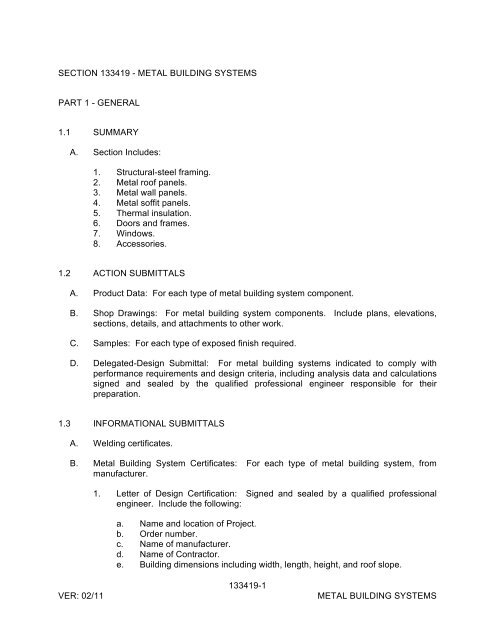
SECTION 133419 - <strong>METAL</strong> <strong>BUILDING</strong> <strong>SYSTEMS</strong><strong>PART</strong> 1 - GENERAL1.1 SUMMARYA. Section Includes:1. Structural-steel framing.2. Metal roof panels.3. Metal wall panels.4. Metal soffit panels.5. Thermal insulation.6. Doors and frames.7. Windows.8. Accessories.1.2 ACTION SUBMITTALSA. Product Data: For each type of metal building system component.B. Shop Drawings: For metal building system components. Include plans, elevations,sections, details, and attachments to other work.C. Samples: For each type of exposed finish required.D. Delegated-Design Submittal: For metal building systems indicated to comply withperformance requirements and design criteria, including analysis data and calculationssigned and sealed by the qualified professional engineer responsible for theirpreparation.1.3 INFORMATIONAL SUBMITTALSA. Welding certificates.B. Metal Building System Certificates: For each type of metal building system, frommanufacturer.1. Letter of Design Certification: Signed and sealed by a qualified professionalengineer. Include the following:a. Name and location of Project.b. Order number.c. Name of manufacturer.d. Name of Contractor.e. Building dimensions including width, length, height, and roof slope.VER: 02/11133419-1<strong>METAL</strong> <strong>BUILDING</strong> <strong>SYSTEMS</strong>
f. Indicate compliance with AISC standards for hot-rolled steel and AISIstandards for cold-rolled steel, including edition dates of each standard.g. Governing building code and year of edition.h. Design Loads: Include dead load, roof live load, collateral loads, roof snowload, deflection, wind loads/speeds and exposure, seismic design categoryor effective peak velocity-related acceleration/peak acceleration, andauxiliary loads (cranes).i. Load Combinations: Indicate that loads were applied acting simultaneouslywith concentrated loads, according to governing building code.j. Building-Use Category: Indicate category of building use and its effect onload importance factors.k. AISC Certification for Category MB: Include statement that metal buildingsystem and components were designed and produced in an AISC-CertifiedFacility by an AISC-Certified Manufacturer.C. Material test reports.D. Source quality-control reports.E. Field quality-control reports.F. Warranties: Sample of special warranties.1.4 CLOSEOUT SUBMITTALSA. Maintenance data.1.5 QUALITY ASSURANCEA. Manufacturer Qualifications: A qualified manufacturer.1. AISC Certification for Category MB: An AISC-Certified Manufacturer thatdesigns and produces metal building systems and components in an AISC-Certified Facility.2. Preparation of Shop Drawings and engineering analysis by a qualifiedprofessional engineer.B. Erector Qualifications: An experienced erector who is acceptable to manufacturer.C. Welding Qualifications: Qualify procedures and personnel according to the following:1. AWS D1.1/D1.1M, "Structural Welding Code - Steel."2. AWS D1.3, "Structural Welding Code - Sheet Steel."D. Structural Steel: Comply with AISC 360, "Specification for Structural Steel Buildings,"for design requirements and allowable stresses.VER: 02/11133419-2<strong>METAL</strong> <strong>BUILDING</strong> <strong>SYSTEMS</strong>
E. Cold-Formed Steel: Comply with AISI's "North American Specification for the Designof Cold-Formed Steel Structural Members" for design requirements and allowablestresses.F. Preinstallation Conference: Conduct conference as directed by SRP PM.1.6 WARRANTYA. Special Warranty on Metal Panel Finishes: Manufacturer's standard form in whichmanufacturer agrees to repair finish or replace metal panels that show evidence ofdeterioration of factory-applied finishes within specified warranty period.1. Finish Warranty Period: 10 years from date of Substantial Completion.B. Special Weathertightness Warranty for Standing-Seam Metal Roof Panels:Manufacturer's standard form in which manufacturer agrees to repair or replacestanding-seam metal roof panel assemblies that leak or otherwise fail to remainweathertight within specified warranty period.1. Warranty Period: 20 years from date of Substantial Completion.<strong>PART</strong> 2 - PRODUCTS2.1 MANUFACTURERSA. Manufacturers: Subject to compliance with requirements, available manufacturersoffering products that may be incorporated into the Work include, but are not limited to,the following:1. A&S Building Systems, Inc.; Division of NCI Building Systems, L.P.2. Alliance Steel, Inc.3. American Buildings Company; Division of Magnatrax Corp.4. American Steel Building Co., Inc.5. BC Steel Buildings, Inc.6. Behlen Mfg. Co.7. Bigbee Steel Buildings, Inc.8. Butler Manufacturing Company; a BlueScope Steel company.9. CBC Steel Buildings; Division of Magnatrax Corp.10. Ceco Building Systems; Division of NCI Building Systems, L.P.11. Chief Buildings; Division of Chief Industries, Inc.12. Elite Structures, Inc.13. Garco Building Systems; Division of NCI Building Systems, L.P.14. Gulf States Manufacturers, Inc.; Division of Magnatrax Corp.133419-3VER: 02/11<strong>METAL</strong> <strong>BUILDING</strong> <strong>SYSTEMS</strong>
15. Inland Buildings; Subsidiary of Behlen Mfg. Co.16. Kirby Building Systems; Division of Magnatrax Corp.17. Mesco Building Solutions; Division of NCI Building Systems, L.P.18. Metallic Building Company; Division of NCI Building Systems, L.P.19. Metco Metal Supply.20. Mid-West Steel Building Company; Division of NCI Building Systems, L.P.21. Nucor Building Systems.22. Oakland Metal Buildings, Inc.23. Olympia Steel Building Systems.24. Package Industries, Inc.25. Pinnacle Structures, Inc.26. Robertson Building Systems; an NCI company.27. Ruffin Building Systems, Inc.28. Schulte Building Systems, LLP.29. Spirco Manufacturing.30. Star Building Systems; an NCI company.31. Tyler Building Systems, L.P.32. USA, Inc.33. VP Buildings; a United Dominion company.34. Vulcan Steel Structures, Inc.35. Whirlwind Building Systems.2.2 <strong>METAL</strong> <strong>BUILDING</strong> SYSTEM PERFORMANCEA. Delegated Design: Design metal building system, including comprehensiveengineering analysis by a qualified professional engineer, using performancerequirements and design criteria indicated.B. Structural Performance: Metal building systems shall be designed according toprocedures in MBMA's "Metal Building Systems Manual."1. Design Loads: As indicated on Drawings.2. Design Loads: As required by MBMA's "Metal Building Systems Manual."3. Deflection Limits: Design metal building system assemblies to withstand designloads with deflections no greater than the following:a. Design secondary-framing system to accommodate deflection of primaryframing and construction tolerances, and to maintain clearances atopenings.VER: 02/11133419-4<strong>METAL</strong> <strong>BUILDING</strong> <strong>SYSTEMS</strong>
4. Metal panel assemblies shall withstand the effects of gravity loads and loads andstresses within limits and under conditions indicated according to ASTM E 1592.C. Seismic Performance: Metal building systems shall withstand the effects of earthquakemotions determined according to ASCE/SEI 7.D. Thermal Movements: Allow for thermal movements resulting from the followingmaximum change (range) in ambient and surface temperatures by preventing buckling,opening of joints, overstressing of components, failure of joint sealants, failure ofconnections, and other detrimental effects. Base engineering calculations on surfacetemperatures of materials due to both solar heat gain and nighttime-sky heat loss.1. Temperature Change (Range): 120 deg F, material surfaces.E. Water Penetration for Metal Roof Panels: No water penetration when tested accordingto ASTM E 1646.F. Water Penetration for Metal Wall Panels: No water penetration when tested accordingto ASTM E 331 at a wind-load design pressure of not less than 2.86 lbf/sq. ft.G. Wind-Uplift Resistance: Provide metal roof panel assemblies that comply with UL 580for Class 30.H. Solar Reflectance Index: Not less than 78 when calculated according to ASTM E 1980based on testing identical products by a qualified testing agency.I. Energy Performance: Provide roof panels that are listed on the DOE's ENERGY STARRoof Products Qualified Product List for low-slope roof products.J. Energy Performance: Provide roof panels with initial solar reflectance not less than0.70 and emissivity not less than 0.75 when tested according to CRRC.2.3 STRUCTURAL-STEEL FRAMINGA. Primary Framing: Manufacturer's standard primary-framing system, designed towithstand required loads and specified requirements. Primary framing includestransverse and lean-to frames; rafter, rake, and canopy beams; sidewall, intermediate,end-wall, and corner columns; and wind bracing.1. General: Provide frames with attachment plates, bearing plates, and splicemembers. Factory drill for field-bolted assembly.B. Bolts: Provide plain-finish bolts for structural-framing components that are primed orfinish painted. Provide zinc-plated or hot-dip galvanized bolts for structural-framingcomponents that are galvanized.C. Finish: Factory primed. Apply specified primer immediately after cleaning andpretreating.VER: 02/11133419-5<strong>METAL</strong> <strong>BUILDING</strong> <strong>SYSTEMS</strong>
2.4 <strong>METAL</strong> ROOF PANELSA. Standing-Seam Metal Roof Panels: Formed with ribs at panel edges and intermediatestiffening ribs symmetrically spaced between ribs; designed for sequential installationby mechanically attaching panels to supports using concealed clips located under oneside of panels and engaging opposite edge of adjacent panels.1. Material: Zinc-coated (galvanized) or Aluminum-zinc alloy-coated steel sheet,0.028-inch nominal thickness.a. Exterior Finish: Minimum Two-coat fluoropolymer.b. Color: As selected by Architect from manufacturer's full range.2. Clips: Manufacturer's standar.3. Joint Type: Panels snapped together.4. Joint Type: Mechanically seamed,folded according to manufacturer's standard.5. Panel Coverage: 16 inches.6. Panel Height: 2 inches.7. Uplift Rating: UL 30B. Tapered-Rib-Profile, Lap-Seam Metal Roof Panels: Formed with raised, trapezoidalmajor ribs and intermediate stiffening ribs symmetrically spaced between major ribs;designed to be installed by lapping side edges of adjacent panels and mechanicallyattaching panels to supports using exposed fasteners in side laps.1. Material: Zinc-coated (galvanized) or Aluminum-zinc alloy-coated steel sheet,0.028-inch nominal thickness.a. Exterior Finish: Minimum Two-coat fluoropolymer.b. Color: As selected by Architect from manufacturer's full range.2. Major-Rib Spacing: 12 inches o.c.3. Panel Coverage: 36 inches4. Panel Height: [0.75 in] [1.125 in] [1.188 in] [1.25 in] [1.5 in].2.5 <strong>METAL</strong> WALL PANELSA. [Tapered-Rib-Profile,] [Reverse-Rib-Profile,] Exposed-Fastener Metal Wall Panels:Formed with raised, trapezoidal major ribs and intermediate stiffening ribssymmetrically spaced between major ribs; designed to be installed by lapping sideedges of adjacent panels and mechanically attaching panels to supports usingexposed fasteners in side laps.1. Material: Zinc-coated (galvanized) or Aluminum-zinc alloy-coated steel sheet,0.028-inch nominal thickness.a. Exterior Finish: Minimum Two-coat fluoropolymer.b. Color: As selected by Architect from manufacturer's full range.2. Major-Rib Spacing: 12 inches o.c.VER: 02/11133419-6<strong>METAL</strong> <strong>BUILDING</strong> <strong>SYSTEMS</strong>
3. Panel Coverage: 36 inches.4. Panel Height: [0.75 inch] [1.125 inches] [1.188 inches] [1.25 inches] [1.5inches].2.6 <strong>METAL</strong> SOFFIT PANELSA. General: Provide factory-formed metal soffit panels designed to be installed by lappingand interconnecting side edges of adjacent panels and mechanically attaching throughpanel to supports using concealed fasteners and sealant in side laps. Includeaccessories required for weathertight installation.B. Metal Soffit Panels: Match profile and material of metal wall panels.1. Finish: Match finish and color of metal wall panels.2.7 THERMAL INSULATIONA. Faced Metal Building Insulation: ASTM C 991, Type II, glass-fiber-blanket insulation;0.5-lb/cu. ft. density; 2-inch- wide, continuous, vapor-tight edge tabs; with a flamespreadindex of 25 or less.B. Unfaced Metal Building Insulation: ASTM C 991, Type I, or NAIMA 202, glass-fiberblanketinsulation; 0.5-lb/cu. ft. density; 2-inch- wide, continuous, vapor-tight edge tabs;with a flame-spread index of 25 or less.1. Vapor-Retarder Facing: ASTM C 1136, with permeance not greater than 0.02perm when tested according to ASTM E 96/E 96M, Desiccant Method.2.8 DOORS AND FRAMESA. Swinging Personnel Doors and Frames: Metal building system manufacturer'sstandard doors and frames; prepared and reinforced at strike and at hinges to receivefactory- and field-applied hardware according to BHMA A156 Series.1. Hardware:a. Provide hardware for each door leaf, as follows:1) Hinges: BHMA A156.1. Three plain-bearing, standard-weight, fullmortise,stainless-steel or bronze, template-type hinges; 4-1/2 by 4-1/2 inches, with nonremovable pin.2) Lockset: BHMA A156.2. [Key-in-lever cylindrical] [Mortise, withlever handle] type.3) Exit Device: BHMA A156.3. Touch- or push-bar type.4) Threshold: BHMA A156.21. Extruded aluminum.5) Silencers: Pneumatic rubber; three silencers on strike jambs ofsingle door frames and two silencers on heads of double doorframes.VER: 02/11133419-7<strong>METAL</strong> <strong>BUILDING</strong> <strong>SYSTEMS</strong>
2. Baked-Enamel Finish: Organic Coating: Thermosetting, modified-acrylic enamelprimer/topcoat system complying with AAMA 2603 except with a minimum dryfilm thickness of 0.7 mil, medium gloss.a. Color: As indicated by manufacturer's designations.2.10 ACCESSORIESA. General: Provide accessories as standard with metal building system manufacturerand as specified. Fabricate and finish accessories at the factory to greatest extentpossible, by manufacturer's standard procedures and processes. Comply withindicated profiles and with dimensional and structural requirements.1. Form exposed sheet metal accessories that are without excessive oil-canning,buckling, and tool marks and that are true to line and levels indicated, withexposed edges folded back to form hems.B. Roof Panel Accessories: Provide components required for a complete metal roof panelassembly including copings, fasciae, corner units, ridge closures, clips, sealants,gaskets, fillers, closure strips, and similar items. Match material and finish of metalroof panels unless otherwise indicated.C. Wall Panel Accessories: Provide components required for a complete metal wall panelassembly including copings, fasciae, mullions, sills, corner units, clips, sealants,gaskets, fillers, closure strips, and similar items. Match material and finish of metalwall panels unless otherwise indicated.D. Flashing and Trim: Formed from 0.022-inch nominal-thickness, metallic-coated steelsheet or aluminum-zinc alloy-coated steel sheet prepainted with coil coating; finished tomatch adjacent metal panels.E. Gutters: Formed from 0.022-inch nominal-thickness, metallic-coated steel sheet oraluminum-zinc alloy-coated steel sheet prepainted with coil coating; finished to matchroof fascia and rake trim. Match profile of gable trim, complete with end pieces, outlettubes, and other special pieces as required. Fabricate in minimum 96-inch- longsections, sized according to SMACNA's "Architectural Sheet Metal Manual."1. Gutter Supports: Fabricated from same material and finish as gutters.2. Strainers: Bronze, copper, or aluminum wire ball type at outlets.F. Downspouts: Formed from 0.022-inch nominal-thickness, zinc-coated (galvanized)steel sheet or aluminum-zinc alloy-coated steel sheet prepainted with coil coating;finished to match metal wall panels. Fabricate in minimum 10-foot- long sections,complete with formed elbows and offsets.1. Mounting Straps: Fabricated from same material and finish as gutters.G. Roof Ventilators: Gravity type, complete with hardware, flashing, closures, and fittings.VER: 02/11133419-9<strong>METAL</strong> <strong>BUILDING</strong> <strong>SYSTEMS</strong>
1. Circular-Revolving Type: Minimum 20-inch- diameter throat opening; finished tomatch metal roof panels; with matching base and rain cap.a. Type: [Directional] [Stationary] revolving.b. Bird Screening: Galvanized steel or aluminum.c. Dampers: Spring-loaded, butterfly type; pull-chain operation; with pullchain of length required to reach within 36 inches of floor.2. Continuous or Sectional-Ridge Type: Factory-engineered and -fabricated,continuous unit; fabricated from 0.022-inch nominal-thickness, metallic-coatedsteel sheet or aluminum-zinc alloy-coated steel sheet prepainted with coilcoating; finished to match metal roof panels. Fabricated in minimum 10-footlongsections. Provide throat size and total length indicated, complete with sidebaffles, ventilator assembly, end caps, splice plates, and reinforcing diaphragms.a. Bird Screening: Galvanized steel or aluminum.b. Dampers: Manually operated, spring-loaded, vertically rising type; chainand worm gear operator; with pull chain of length required to reach within36 inches of floor.c. Throat Size: 9 or 12 inches, as standard with manufacturer, and asrequired to comply with ventilation requirements.H. Roof Curbs: Fabricated from minimum 0.052-inch nominal-thickness, metallic-coatedsteel sheet or aluminum-zinc alloy-coated steel sheet prepainted with coil coating;finished to match metal roof panels; capable of withstanding loads of size and heightindicated.I. Pipe Flashing: Premolded, EPDM pipe collar with flexible aluminum ring bonded tobase.2.11 SOURCE QUALITY CONTROLA. Testing Agency: Owner will engage a qualified testing agency to evaluate product.B. Special Inspector: Owner will engage a qualified special inspector to perform thefollowing tests and inspections and to submit reports. Special inspector will verify thatmanufacturer maintains detailed fabrication and quality-control procedures and willreview the completeness and adequacy of those procedures to perform the Work.1. Special inspections will not be required if fabrication is performed bymanufacturer registered and approved by authorities having jurisdiction toperform such Work without special inspection.a. After fabrication, submit copy of certificate of compliance to authoritieshaving jurisdiction, certifying that Work was performed according toContract requirements.C. Testing: Test and inspect shop connections for metal buildings according to thefollowing:VER: 02/11133419-10<strong>METAL</strong> <strong>BUILDING</strong> <strong>SYSTEMS</strong>
1. Bolted Connections: Shop-bolted connections shall be inspected according toRCSC's "Specification for Structural Joints Using ASTM A 325 or A 490 Bolts."2. Welded Connections: In addition to visual inspection, shop-welded connectionsshall be tested and inspected according to AWS D1.1/D1.1M and the followinginspection procedures, at inspector's option:a. Liquid Penetrant Inspection: ASTM E 165.b. Magnetic Particle Inspection: ASTM E 709; performed on root pass and onfinished weld. Cracks or zones of incomplete fusion or penetration will notbe accepted.c. Ultrasonic Inspection: ASTM E 164.d. Radiographic Inspection: ASTM E 94.D. Product will be considered defective if it does not pass tests and inspections.E. Prepare test and inspection reports.2.12 FABRICATIONA. General: Design components and field connections required for erection to permiteasy assembly.1. Mark each piece and part of the assembly to correspond with previouslyprepared erection drawings, diagrams, and instruction manuals.2. Fabricate structural framing to produce clean, smooth cuts and bends. Punchholes of proper size, shape, and location. Members shall be free of cracks,tears, and ruptures.B. Tolerances: Comply with MBMA's "Metal Building Systems Manual" for fabrication anderection tolerances.C. Primary Framing: Shop fabricate framing components to size and section, withbaseplates, bearing plates, stiffeners, and other items required for erection welded intoplace. Cut, form, punch, drill, and weld framing for bolted field assembly.D. Secondary Framing: Shop fabricate framing components to size and section by rollformingor break-forming, with baseplates, bearing plates, stiffeners, and other platesrequired for erection welded into place. Cut, form, punch, drill, and weld secondaryframing for bolted field connections to primary framing.E. Metal Panels: Fabricate and finish metal panels at the factory to greatest extentpossible, by manufacturer's standard procedures and processes, as necessary to fulfillindicated performance requirements. Comply with indicated profiles and withdimensional and structural requirements.VER: 02/11133419-11<strong>METAL</strong> <strong>BUILDING</strong> <strong>SYSTEMS</strong>
<strong>PART</strong> 3 - EXECUTION3.1 ERECTION OF STRUCTURAL FRAMINGA. Do not field cut, drill, or alter structural members without written approval from metalbuilding system manufacturer's professional engineer.B. Set structural framing accurately in locations and to elevations indicated, according toAISC specifications referenced in this Section. Maintain structural stability of frameduring erection.C. Base and Bearing Plates: Clean concrete- and masonry-bearing surfaces of bondreducingmaterials, and roughen surfaces prior to setting plates. Clean bottom surfaceof plates.1. Set plates for structural members on wedges, shims, or setting nuts as required.2. Tighten anchor rods after supported members have been positioned andplumbed. Do not remove wedges or shims but, if protruding, cut off flush withedge of plate before packing with grout.3. Promptly pack grout solidly between bearing surfaces and plates so no voidsremain. Neatly finish exposed surfaces; protect grout and allow to cure. Complywith manufacturer's written installation instructions for shrinkage-resistant grouts.D. Align and adjust structural framing before permanently fastening. Before assembly,clean bearing surfaces and other surfaces that will be in permanent contact withframing. Perform necessary adjustments to compensate for discrepancies inelevations and alignment.1. Level and plumb individual members of structure.2. Make allowances for difference between temperature at time of erection andmean temperature when structure will be completed and in service.E. Primary Framing and End Walls: Erect framing level, plumb, rigid, secure, and true toline. Level baseplates to a true even plane with full bearing to supporting structures,set with double-nutted anchor bolts. Use grout to obtain uniform bearing and tomaintain a level base-line elevation. Moist-cure grout for not less than seven daysafter placement.1. Make field connections using high-strength bolts installed according to RCSC's"Specification for Structural Joints Using ASTM A 325 or A 490 Bolts" for bolttype and joint type specified.a. Joint Type: Snug tightened or pretensioned.F. Secondary Framing: Erect framing level, plumb, rigid, secure, and true to line. Fieldbolt secondary framing to clips attached to primary framing.1. Provide rake or gable purlins with tight-fitting closure channels and fasciae.2. Locate and space wall girts to suit openings such as doors and windows.3. Locate canopy framing as indicated.VER: 02/11133419-12<strong>METAL</strong> <strong>BUILDING</strong> <strong>SYSTEMS</strong>
4. Provide supplemental framing at entire perimeter of openings, including doors,windows, louvers, ventilators, and other penetrations of roof and walls.G. Steel Joists: Install joists and accessories plumb, square, and true to line; securelyfasten to supporting construction according to SJI's "Standard Specifications and LoadTables for Steel Joists and Joist Girders," joist manufacturer's written instructions, andrequirements in this Section.1. Before installation, splice joists delivered to Project site in more than one piece.2. Space, adjust, and align joists accurately in location before permanentlyfastening.3. Install temporary bracing and erection bridging, connections, and anchors toensure that joists are stabilized during construction.4. Bolt joists to supporting steel framework using carbon-steel bolts unless highstrengthstructural bolts are required by the manufacturer.5. Comply with RCSC's "Specification for Structural Joints Using ASTM A 325 orA 490 Bolts" for high-strength structural bolt installation and tighteningrequirements.6. Install and connect bridging concurrently with joist erection, before constructionloads are applied. Anchor ends of bridging lines at top and bottom chords ifterminating at walls or beams.H. Bracing: Install bracing in roof and sidewalls where indicated on erection drawings.1. Tighten rod and cable bracing to avoid sag.2. Locate interior end-bay bracing only where indicated.I. Framing for Openings: Provide shapes of proper design and size to reinforce openingsand to carry loads and vibrations imposed, including equipment furnished undermechanical and electrical work. Securely attach to structural framing.J. Erection Tolerances: Maintain erection tolerances of structural framing withinAISC 303.3.2 <strong>METAL</strong> PANEL INSTALLATION, GENERALA. General: Anchor metal panels and other components of the Work securely in place,with provisions for thermal and structural movement.1. Field cut metal panels as required for doors, windows, and other openings. Cutopenings as small as possible, neatly to size required, and without damage toadjacent metal panel finishes.a. Field cutting of metal panels by torch is not permitted unless approved inwriting by manufacturer.2. Install metal panels perpendicular to structural supports unless otherwiseindicated.3. Flash and seal metal panels with weather closures at perimeter of openings andsimilar elements. Fasten with self-tapping screws.VER: 02/11133419-13<strong>METAL</strong> <strong>BUILDING</strong> <strong>SYSTEMS</strong>
4. Locate and space fastenings in uniform vertical and horizontal alignment.5. Locate metal panel splices over, but not attached to, structural supports with endlaps in alignment.6. Lap metal flashing over metal panels to allow moisture to run over and off thematerial.B. Lap-Seam Metal Panels: Install screw fasteners using power tools with controlledtorque adjusted to compress EPDM washers tightly without damage to washers, screwthreads, or metal panels. Install screws in predrilled holes.1. Arrange and nest side-lap joints so prevailing winds blow over, not into, lappedjoints. Lap ribbed or fluted sheets one full rib corrugation. Apply metal panelsand associated items for neat and weathertight enclosure. Avoid "panel creep"or application not true to line.C. Metal Protection: Where dissimilar metals contact each other or corrosive substrates,protect against galvanic action by painting contact surfaces with corrosion-resistantcoating, by applying rubberized-asphalt underlayment to each contact surface, or byother permanent separation as recommended by metal roof panel manufacturer.D. Joint Sealers: Install gaskets, joint fillers, and sealants where indicated and whererequired for weatherproof performance of metal panel assemblies. Provide types ofgaskets, fillers, and sealants recommended by metal panel manufacturer.1. Seal metal panel end laps with double beads of tape or sealant the full width ofpanel. Seal side joints where recommended by metal panel manufacturer.2. Prepare joints and apply sealants to comply with requirements in Section 079200"Joint Sealants."3.3 <strong>METAL</strong> ROOF PANEL INSTALLATIONA. General: Provide metal roof panels of full length from eave to ridge unless otherwiseindicated or restricted by shipping limitations.1. Install ridge and hip caps as metal roof panel work proceeds.2. Flash and seal metal roof panels with weather closures at eaves and rakes.Fasten with self-tapping screws.B. Standing-Seam Metal Roof Panels: Fasten metal roof panels to supports withconcealed clips at each standing-seam joint, at location and spacing and with fastenersrecommended by manufacturer.1. Install clips to supports with self-drilling or self-tapping fasteners.2. Install pressure plates at locations indicated in manufacturer's written installationinstructions.3. Snap Joint: Nest standing seams and fasten together by interlocking andcompletely engaging factory-applied sealant.4. Seamed Joint: Crimp standing seams with manufacturer-approved motorizedseamer tool so that clip, metal roof panel, and factory-applied sealant arecompletely engaged.VER: 02/11133419-14<strong>METAL</strong> <strong>BUILDING</strong> <strong>SYSTEMS</strong>
5. Rigidly fasten eave end of metal roof panels and allow ridge end free movementdue to thermal expansion and contraction. Predrill panels for fasteners.6. Provide metal closures at [peaks] [rake edges] [rake walls] [and] each side ofridge[ and hip] caps.C. Lap-Seam Metal Roof Panels: Fasten metal roof panels to supports with exposedfasteners at each lapped joint, at location and spacing recommended by manufacturer.1. Provide metal-backed sealing washers under heads of exposed fastenersbearing on weather side of metal roof panels.2. Provide sealant tape at lapped joints of metal roof panels and between panelsand protruding equipment, vents, and accessories.3. Apply a continuous ribbon of sealant tape to weather-side surface of fasteningson end laps and on side laps of nesting-type metal panels, on side laps of ribbedor fluted metal panels, and elsewhere as needed to make metal panelsweatherproof to driving rains.4. At metal panel splices, nest panels with minimum 6-inch end lap, sealed withbutyl-rubber sealant and fastened together by interlocking clamping plates.D. Metal Fascia Panels: Align bottom of metal panels and fasten with blind rivets, bolts,or self-drilling or self-tapping screws. Flash and seal metal panels with weatherclosures where fasciae meet soffits, along lower panel edges, and at perimeter of allopenings.3.4 <strong>METAL</strong> WALL PANEL INSTALLATIONA. General: Install metal wall panels in orientation, sizes, and locations indicated onDrawings. Install panels perpendicular to girts, extending full height of building, unlessotherwise indicated. Anchor metal wall panels and other components of the Worksecurely in place, with provisions for thermal and structural movement.VER: 02/111. Unless otherwise indicated, begin metal panel installation at corners with centerof rib lined up with line of framing.2. Shim or otherwise plumb substrates receiving metal wall panels.3. When two rows of metal panels are required, lap panels 4 inches minimum.4. When building height requires two rows of metal panels at gable ends, align lapof gable panels over metal wall panels at eave height.5. Rigidly fasten base end of metal wall panels and allow eave end free movementdue to thermal expansion and contraction. Predrill panels.6. Flash and seal metal wall panels with weather closures at eaves, rakes, and atperimeter of all openings. Fasten with self-tapping screws.7. Install screw fasteners in predrilled holes.8. Install flashing and trim as metal wall panel work proceeds.9. Apply elastomeric sealant continuously between metal base channel (sill angle)and concrete, and elsewhere as indicated; or, if not indicated, as necessary forwaterproofing.10. Align bottom of metal wall panels and fasten with blind rivets, bolts, or self-drillingor self-tapping screws.11. Provide weatherproof escutcheons for pipe and conduit penetrating exteriorwalls.133419-15<strong>METAL</strong> <strong>BUILDING</strong> <strong>SYSTEMS</strong>
a. Thermal Spacer Blocks: Where metal roof panels attach directly to purlins,install thermal spacer blocks.5. Retainer Strips: Install retainer strips at each longitudinal insulation joint, straightand taut, nesting with secondary framing to hold insulation in place.C. Blanket Wall Insulation: Extend insulation and vapor retarder over and perpendicularto top flange of secondary framing. Hold in place by metal wall panels fastened tosecondary framing.1. Retainer Strips: Install retainer strips at each longitudinal insulation joint, straightand taut, nesting with secondary framing to hold insulation in place.2. Sound-Absorption Insulation: Where sound-absorption requirement is indicatedfor metal liner panels, cover insulation with polyethylene film and provide insertsof wire mesh to form acoustical spacer grid.3.7 DOOR AND FRAME INSTALLATIONA. General: Install doors and frames plumb, rigid, properly aligned, and securely fastenedin place according to manufacturers' written instructions. Coordinate installation withwall flashings and other components. Seal perimeter of each door frame withelastomeric sealant used for metal wall panels.B. Personnel Doors and Frames: Install doors and frames according to SDI A250.8.C. Field Glazing: Comply with installation requirements in Section 088000 "Glazing."D. Door Hardware: Mount units at heights indicated in DHI's "Recommended Locationsfor Architectural Hardware for Standard Steel Doors and Frames."1. Install surface-mounted items after finishes have been completed on substratesinvolved.2. Set units level, plumb, and true to line and location. Adjust and reinforceattachment substrates as necessary for proper installation and operation.3. Drill and countersink units that are not factory prepared for anchorage fasteners.Space fasteners and anchors according to industry standards.4. Set thresholds for exterior doors in full bed of butyl-rubber sealant complying withrequirements specified in Section 079200 "Joint Sealants."3.8 WINDOW INSTALLATIONA. General: Install windows plumb, rigid, properly aligned, without warp or rack of framesor sash, and securely fasten in place according to manufacturer's written instructions.Coordinate installation with wall flashings and other components. Seal perimeter ofeach window frame with elastomeric sealant used for metal wall panels.1. Separate dissimilar materials from sources of corrosion or electrolytic action atpoints of contact with other materials by complying with requirements specified inAAMA/WDMA/CSA 101/I.S.2/A440.VER: 02/11133419-17<strong>METAL</strong> <strong>BUILDING</strong> <strong>SYSTEMS</strong>
D. Downspouts: Join sections with 1-1/2-inch telescoping joints. Provide fastenersdesigned to hold downspouts securely 1 inch away from walls; locate fasteners at topand bottom and at approximately 60 inches o.c. in between.1. Provide elbows at base of downspouts to direct water away from building.2. Tie downspouts to underground drainage system indicated.E. Circular Roof Ventilators: Set ventilators complete with necessary hardware, anchors,dampers, weather guards, rain caps, and equipment supports. Mount ventilators onflat level base. Install preformed filler strips at base to seal ventilator to metal roofpanels.F. Continuous Roof Ventilators: Set ventilators complete with necessary hardware,anchors, dampers, weather guards, rain caps, and equipment supports. Join sectionswith splice plates and end-cap skirt assemblies where required to achieve indicatedlength. Install preformed filler strips at base to seal ventilator to metal roof panels.G. Roof Curbs: Install curbs at locations indicated on Drawings. Install flashing aroundbases where they meet metal roof panels.H. Pipe Flashing: Form flashing around pipe penetration and metal roof panels. Fastenand seal to panel as recommended by manufacturer.3.10 FIELD QUALITY CONTROLA. Special Inspections: Owner will engage a qualified special inspector to perform specialinspections.B. Testing Agency: Owner will engage a qualified testing agency to perform tests andinspections.C. Tests and Inspections:1. High-Strength, Field-Bolted Connections: Connections shall be[ tested and]inspected during installation according to RCSC's "Specification for StructuralJoints Using ASTM A 325 or A 490 Bolts."2. Welded Connections: In addition to visual inspection, field-welded connectionsshall be tested and inspected according to AWS D1.1/D1.1M and the followinginspection procedures, at inspector's option:a. Liquid Penetrant Inspection: ASTM E 165.b. Magnetic Particle Inspection: ASTM E 709; performed on root pass and onfinished weld. Cracks or zones of incomplete fusion or penetration will notbe accepted.c. Ultrasonic Inspection: ASTM E 164.d. Radiographic Inspection: ASTM E 94.D. Product will be considered defective if it does not pass tests and inspections.E. Prepare test and inspection reports.VER: 02/11133419-19<strong>METAL</strong> <strong>BUILDING</strong> <strong>SYSTEMS</strong>
END OF SECTION 133419VER: 02/11133419-20<strong>METAL</strong> <strong>BUILDING</strong> <strong>SYSTEMS</strong>