Thermal Stress Analysis of a Flip-Chip Parallel VCSEL - ECA Digital ...
Thermal Stress Analysis of a Flip-Chip Parallel VCSEL - ECA Digital ...
Thermal Stress Analysis of a Flip-Chip Parallel VCSEL - ECA Digital ...

Create successful ePaper yourself
Turn your PDF publications into a flip-book with our unique Google optimized e-Paper software.
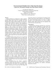
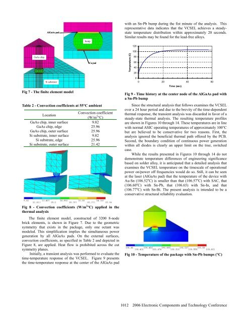
AlGaAs padbumpwith an Sn-Pb bump during the fist minute <strong>of</strong> the analysis. Thisrepresentative data indicates that the <strong>VCSEL</strong> achieves a steadystatetemperature distribution within approximately 20 seconds.Similar results may be found for the lead-free alloys.120100GaAs chipCu padTemperature (C)80604020Si substrateFig 7 - The finite element modelTable 2 - Convection coefficients at 55°C ambientLocationConvection coefficient(W/m 2 °C)GaAs chip, inner surface 9.82GaAs chip, edge 25.96GaAs chip, outer surface 25.96Si substrate, inner surface 9.82Si substrate, edge 25.96Si substrate, outer surface 21.4200 20 40 60Time (sec)Fig 9 - Time history at the center node <strong>of</strong> the AlGaAs pad witha Sn-Pb bumpSince the structural analysis that follows examines the <strong>VCSEL</strong>over a 24 hour period and due to the brevity <strong>of</strong> the time-dependentthermal response, the transient analysis was discarded in favor <strong>of</strong> asteady-state thermal analysis. The resulting temperature pr<strong>of</strong>ilesare shown in Figures 10 through 14. These temperatures are in linewith normal ASIC operating temperatures <strong>of</strong> approximately 100°Cbut are believed to be conservative for two reasons. First, theanalysis ignored the beneficial thermal path <strong>of</strong>fered by the PCB.Second, the boundary condition <strong>of</strong> continuous power generationwithin all diodes is clearly an upper limit on the true, switchedcase.While the results presented in Figures 10 through 14 do notdemonstrate temperature differences <strong>of</strong> engineering significancebased on solder alloy, it is anticipated that a detailed analysis thatexamines the <strong>VCSEL</strong> temperature on the timescale <strong>of</strong> operationalpower on/power <strong>of</strong>f frequencies would do so. Still, it can be seenat the laser (AlGaAs pad) that the temperature <strong>of</strong> the device withAu-Sn (106.52 o C) is smaller than that (106.57 o C) with SAC, that(106.60 o C) with Sn-Pb, that (106.65) with Sn-In, and that(106.77 o C) with Sn-Bi. The present analysis is intended to be aconservative structural reliability evaluation.Fig 8 - Convection coefficients (W/m 2 °C) applied in thethermal analysisThe finite element model, constructed <strong>of</strong> 3200 8-nodebrick elements, is shown in Figure 7. Due to the geometricsymmetry that exists in the package, only one octant wasmodeled. This simplification implies the simultaneous powergeneration by all AlGaAs pads. On the external surfaces,convection coefficients, as specified in Table 2 and depicted inFigure 8, are applied. Heat flow is prohibited across the cutsymmetry planes.Initially, a transient analysis was performed to evaluate thetime-temperature response <strong>of</strong> the <strong>VCSEL</strong>. Figure 9 presentsthe time-temperature response at the center <strong>of</strong> the AlGaAs padFig 10 - Temperature <strong>of</strong> the package with Sn-Pb bumps (°C)1012 2006 Electronic Components and Technology Conference