Steel-Backed Timber Guardrail Design and Construction Notes for ...
Steel-Backed Timber Guardrail Design and Construction Notes for ...
Steel-Backed Timber Guardrail Design and Construction Notes for ...
- No tags were found...

You also want an ePaper? Increase the reach of your titles
YUMPU automatically turns print PDFs into web optimized ePapers that Google loves.
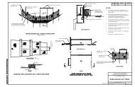
<strong>Steel</strong>-<strong>Backed</strong> <strong>Timber</strong> <strong>Guardrail</strong><strong>Design</strong> <strong>and</strong> <strong>Construction</strong> <strong>Notes</strong> <strong>for</strong>Aesthetic Barriers<strong>Steel</strong>-backed <strong>Timber</strong> <strong>Guardrail</strong> (January 15, 2002)1. The steel-backed timber guardrail has been crash tested <strong>and</strong> meets therequirements of NCHRP Report 350. The blocked-out option, type A, is approved<strong>for</strong> Test Level 3 (design speeds of 100 km/h <strong>and</strong> less). The option without theblock-out, type B, is approved <strong>for</strong> use <strong>for</strong> Test Level 2 (design speeds of 70 km/h<strong>and</strong> less). The preferred installation is the type A.2. Numerous designs <strong>for</strong> the steel-backed timber guardrail <strong>and</strong> its terminals havebeen reviewed <strong>and</strong> tested during the development of this system. Federal L<strong>and</strong>sHighway St<strong>and</strong>ard Drawings <strong>for</strong> berms, turn-down terminals, <strong>and</strong> back-slopeanchored terminals reflect the best compromise of safety, aesthetics, <strong>and</strong> ease ofconstruction. Due to the possible effect on the crashworthiness of the guardrail,any modifications to Federal L<strong>and</strong>s Highway St<strong>and</strong>ards <strong>for</strong> the steel-backedtimber guardrail must be approved by the Federal L<strong>and</strong>s Highway Office.3. The grading in front <strong>and</strong> directly behind the guardrail <strong>and</strong> terminals must be at aslope of 1:10 or flatter <strong>for</strong> the guardrail to be effective.4. The maximum dynamic deflection of the steel-backed timber guardrail isapproximately 215 mm <strong>for</strong> design speed of 70 km/h. The dynamic deflection isapproximately 580 mm <strong>for</strong> design speed of 100 km/h. The back of the rail must beset at least these distances from a fixed objects, such as a tree or bridge pier.5. Field modifications to the structural steel, such as enlargement of the bolt slots,are not permitted, due to the effect on the crashworthiness of the system.6. There should be at least 600 mm between the back of the guardrail posts <strong>and</strong> thetop of a 1:2 slope or steeper. If this is unobtainable, the length of the guardrailposts should be increased to 2.4 m. The increase strength of the 2.4 m postswithout the 600 mm soil backup is marginal <strong>and</strong> should only be used <strong>for</strong> shortsegments.7. The Federal L<strong>and</strong>s Highway Office has st<strong>and</strong>ard drawings designed specifically<strong>for</strong> the steel-backed timber guardrail <strong>for</strong> a back-slope anchored terminal, a berm,<strong>and</strong> a flared anchored terminal (turn-down), <strong>and</strong> may be used:a. Where there is a back-slope to tie to, the preferred terminal is the backslopeanchored terminal (BAT). This terminal has been approved <strong>for</strong> useby the Federal Highway Administration. The terminal used with the typeA block-out is approved <strong>for</strong> NCHRP 350, Test Level 3. The Type B, nonblockedsystem is approved <strong>for</strong> NCHRP 350, Test Level 2. The Crash
tests with similar designs with W-beam guardrail have established aweakness in this design where the guardrail crosses a ditch. Due to thisweakness, ditches under this terminal should be as flat as possible. It isrecommended that the sideslopes of the ditches be no steeper than 1:10.b. Where there is adequate room, <strong>and</strong> no back-slope to tie to, the preferredterminal is the flared anchored terminal (FAT) with an earth berm. theterminal section should be located outside the clear zone. The earth bermshould be oriented approximately parallel to the roadway. It is intendedthat each berm will be stacked to fit its particular location. For safety,aesthetics, <strong>and</strong> maintenance considerations, it is desirable to flatten theslopes of the berm as much as possible. A 1:3 sideslope on the bermfacing the roadway is considered minimally acceptable. It is also desirableto increase the height of the berm, but the 1:20 approach slope must bemaintained.c. Where it is not possible to construct an earth berm or tie to a backslope,the guardrail may be terminated using the FAT without a berm. Crash testson similar turn-down designs have demonstrated the potential <strong>for</strong> this typeterminal to launch a vehicle or produce a rollover. However, this terminalis superior to leaving the exposed guardrail end that could snag or evenpenetrate a vehicle. The widened shoulder area <strong>and</strong> guardrail flare aids isproviding stability <strong>for</strong> a vehicle riding up on the terminal.8. The Federal L<strong>and</strong>s Highway Office has st<strong>and</strong>ard drawings design specifically <strong>for</strong>the steel-backed timber guardrail to connect to a straight parapet wall. Currentlythe only approved transition that has been successfully tested to NCHRP 350 testlevels is a transition to a straight parapet/wall utilizing a rub-rail. This transitionwas tested to NCHRP 350, Test Level 2 (design speeds of 70 km/h <strong>and</strong> less).Additional transitions are currently being revised <strong>for</strong> approval by the FederalHighway Administration.