Final Report A Comparison of Mobile Scanning to a Total Station ...
Final Report A Comparison of Mobile Scanning to a Total Station ...
Final Report A Comparison of Mobile Scanning to a Total Station ...

You also want an ePaper? Increase the reach of your titles
YUMPU automatically turns print PDFs into web optimized ePapers that Google loves.
<strong>Final</strong> <strong>Report</strong>A <strong>Comparison</strong> <strong>of</strong> <strong>Mobile</strong> <strong>Scanning</strong> <strong>to</strong> a <strong>Total</strong> <strong>Station</strong> Surveyat the I-35 and IA 92 Interchangein Warren County, IowaAugust 15, 2012Norm MillerBrian SmithKent NicholsonOffice <strong>of</strong> DesignIowa Department <strong>of</strong> TransportationSponsored by the Iowa Department <strong>of</strong> Transportationandthe Federal Highway AdministrationSPR funded. Iowa DOT Project RB22-011
Disclaimer NoticeThe contents opinions, findings, and conclusions expressed in this publication are those<strong>of</strong> the authors and not necessarily those <strong>of</strong> the Federal Highway Administration.This report does not constitute a standard, specification, or regulation. The sponsors donot endorse products or manufacturers. Trademarks or manufacturer’s names appear inthis report only because they are considered essential <strong>to</strong> the objectives <strong>of</strong> thedocument.Statement <strong>of</strong> Non-DiscriminationFederal and state laws prohibit employment and/or public accommodationdiscrimination on the basis <strong>of</strong> age, color, creed, disability, gender identity, nationalorigin, pregnancy, race, religion sex, sexual orientation or veteran’s status. If you believeyou have been discriminated against, please contact the Iowa Civil Rights Commission at800-457-4416 or Iowa Department <strong>of</strong> Transportation’s affirmative action <strong>of</strong>ficer. If youneed accommodations because <strong>of</strong> a disability <strong>to</strong> access the Iowa Department <strong>of</strong>Transportation’s services, contact the agency’s affirmative action <strong>of</strong>ficer at 800-262-0003.
1. <strong>Report</strong> No.RB22-0112. Government Accession No.N/A4 Title and SubtitleA <strong>Comparison</strong> <strong>of</strong> <strong>Mobile</strong> <strong>Scanning</strong> <strong>to</strong> a <strong>Total</strong> <strong>Station</strong> Survey atthe I-35 and IA 92 Interchange in Warren County, Iowa7. Author(s)Iowa DOT: Norm Miller, Brian Smith, Kent Nicholson.9 Performing Organization Name and AddressIowa Department <strong>of</strong> Transportation800 Lincoln WayAmes, IA 50010REY Engineers, Inc.12 Sponsoring Organization Name and AddressIowa Department <strong>of</strong> Transportation800 Lincoln WayAmes, IA 50010Federal Highway Administration15 Supplementary Notes3. Recipient Catalog No.N/A5 <strong>Report</strong> DateAugust 15, 20126 Performing Organization CodeSPR8 Performing Organization <strong>Report</strong> No.RB22-01110 Work Unit No. (TRAIS)N/A11 Contract or Grant No.N/A13 Type <strong>of</strong> <strong>Report</strong> and Period Covered<strong>Final</strong>. 201214 Sponsoring Agency CodeSPR 90-00-RB22-01116 AbstractThe purpose <strong>of</strong> this project was <strong>to</strong> investigate the potential for collecting and using data from mobile terrestrial laser scanning(MTLS) technology that would reduce the need for traditional survey methods for the development <strong>of</strong> highway improvementprojects at the Iowa Department <strong>of</strong> Transportation (Iowa DOT). The primary interest in investigating mobile scanningtechnology is <strong>to</strong> minimize the exposure <strong>of</strong> field surveyors <strong>to</strong> dangerous high volume traffic situations.Issues investigated were cost, timeframe, accuracy, contracting specifications, data capture extents, data extraction capabilitiesand data s<strong>to</strong>rage issues associated with mobile scanning. The project area selected for evaluation was the I-35/IA 92interchange in Warren County, Iowa. This project covers approximately one mile <strong>of</strong> I-35, one mile <strong>of</strong> IA 92, 4 interchangeramps, and bridges within these limits.Delivered LAS and image files for this project <strong>to</strong>taled almost 31GB. There is nearly a 6-fold increase in the size <strong>of</strong> the scandata after post-processing. Camera data, when enabled, produced approximately 900MB <strong>of</strong> imagery data per mile using a 2-camera, 5 megapixel system.A comparison was done between 1823 points on the pavement that were surveyed by Iowa DOT staff using a <strong>to</strong>tal station andthe same points generated through the MTLS process. The data acquired through the MTLS and data processing met the IowaDOT specifications for engineering survey.A list <strong>of</strong> benefits and challenges is included in the detailed report. With the success <strong>of</strong> this project, it is anticipate thatadditional projects will be scanned for the Iowa DOT for use in the development <strong>of</strong> highway improvement projects.17 Key Words<strong>Mobile</strong> mapping – survey – highway design – scanning –<strong>to</strong>tal station19 Security Classification(<strong>of</strong> this report)UnclassifiedForm DOT F 1700.7 (8-72)20 Security Classification(<strong>of</strong> this page)Unclassified18 Distribution StatementNo restrictions. This document isavailable <strong>to</strong> the public through theNational Technical Information Service,Springfield, Virginia 2216121 No. <strong>of</strong> pages2222 PriceN/A
Iowa DOT SPR RB22-011 Aug 2012A <strong>Comparison</strong> <strong>of</strong> <strong>Mobile</strong> <strong>Scanning</strong> <strong>to</strong> a <strong>Total</strong> <strong>Station</strong> Survey at the I-35 and IA 92 Interchange in Warren County, Iowa.Project TeamIowa DOT: Alice Welch, Norm Miller, Jonathan Miranda, Mike Rummelhart, ChadHightshoe, Brian Smith, Kent Nicholson. REY Engineers, Inc.Project Summary and ObjectivesThe purpose <strong>of</strong> this project was <strong>to</strong> investigate the potential for collecting and using data frommobile terrestrial laser scanning (MTLS) technology that would reduce the need fortraditional survey methods for the development <strong>of</strong> highway improvement projects at the IowaDepartment <strong>of</strong> Transportation (Iowa DOT). The primary interest in investigating mobilescanning technology is <strong>to</strong> minimize the exposure <strong>of</strong> field surveyors <strong>to</strong> dangerous high volumetraffic situations. Additional benefits <strong>to</strong> explore were cost savings and reducing the timerequired <strong>to</strong> produce the survey information.The definition <strong>of</strong> mobile scanning technologies for this project is a system that uses multiplelight detection and ranging (LiDAR) scanners for data capture from a vehicle, whilesimultaneously recording positional data using a Global Positioning System (GPS), inertiameasurement units (IMU), a distance measurement indica<strong>to</strong>r (DMI), and cameras. Theresulting data cloud will contain highly accurate 3-dimensional (3D) locations <strong>of</strong> <strong>to</strong>pographicfeatures <strong>of</strong> the roadway and associated features.Issues <strong>to</strong> be investigated are the cost, timeframe, accuracy, contracting specifications, datacapture extents, data extraction capabilities and data s<strong>to</strong>rage issues associated with mobilescanning. The project area selected for evaluation was the I-35/IA 92 interchange in WarrenCounty, Iowa, as shown between the Yellow bars in the project overview image. This projectcovers approximately one mile <strong>of</strong> I-35, one mile <strong>of</strong> IA 92, 4 interchange ramps, and thebridges within these limits.This interchange was selected because it represents a typical rural setting where engineeringsurvey data is required and where the Iowa DOT is challenged with obtaining a significantnumber <strong>of</strong> field points in areas <strong>of</strong> high traffic volumes. This site was also selected becausethe Iowa DOT recently collected the survey data at this interchange using a <strong>to</strong>tal station andtraditional survey methods. The traditional project data was be used for the comparison withthe data collected through the mobile scanning process.The mobile scanning survey firm was selected through a pr<strong>of</strong>essional proposal process thatfocused on MTLS data collection, break line extraction and file delivery. R.E.Y. Engineers,Inc. <strong>of</strong> Folsom, CA in partnership with Foth Infrastructure & Environment, LLC <strong>of</strong> Johns<strong>to</strong>n,IA were selected for this project.Page 1 <strong>of</strong> 19
Iowa DOT SPR RB22-011 Aug 2012Control Pt.G063Project OverviewI-35/IA 92 Interchange in Warren, County, IowaPreliminary Target Locations Shown in RedPage 2 <strong>of</strong> 19
Iowa DOT SPR RB22-011 Aug 2012Literature Search“Kinematic Terrestrial Light-Detection and Ranging System for <strong>Scanning</strong>”Craig Glennie, Transportation Research Record, No. 2105, 135–141, 2009.Citation at http://dx.doi.org/10.3141/2105-17Abstract: Highway corridor surveys are becoming more difficult and expensive <strong>to</strong> carry outbecause <strong>of</strong> the need <strong>to</strong> minimize lane closures, traffic disruptions, and safety hazards posed <strong>to</strong>the surveyors and public. Roadway surveyors are at risk when working in the traffic corridorif they are unable <strong>to</strong> move with the flow <strong>of</strong> traffic. Safety for the traveling public is also aconcern when lanes are closed or blocked by slow-moving vehicles. Costs for the placement<strong>of</strong> safety features <strong>to</strong> protect a survey crew can in some instances be greater than the cost <strong>of</strong> thesurvey itself. To mitigate these problems, a survey data acquisition <strong>to</strong>ol is needed that cancollect <strong>to</strong>pographic and infrastructure information without disrupting traffic flow. Terrapointhas developed a novel kinematic laser scanning system that can be deployed on a passengervehicle or small watercraft. Light-detection and ranging (LIDAR) digital imagery and videoare collected from the survey platform while it is moving at traffic speeds. The system isgeoreferenced with a high-accuracy Global Positioning System–inertial measurement unit.Terrapoint’s mobile LIDAR scanner has successfully surveyed existing highway corridors allover North America. It has also proven sufficiently accurate for scanning airport runwaysurfaces so as <strong>to</strong> predict areas where water will pool. Moving with the traffic flow and notrequiring an escort, the system scans a 360° swath that includes the pavement surface andobjects <strong>to</strong> the sides and above the survey vehicle.“Geometric validation <strong>of</strong> a ground-based mobile laser scanning system”David Barber, Jon Mills and Sarah Smith-Voysey, ISPRS Journal <strong>of</strong> Pho<strong>to</strong>grammetry andRemote Sensing, Vol. 63, No. 1, 128–141, 2008.Citation at http://linkinghub.elsevier.com/retrieve/pii/S0924271607000834Abstract: This paper outlines a study, carried out on behalf <strong>of</strong> a national mapping agency, <strong>to</strong>validate laser scanned point cloud data collected by a ground-based mobile mapping system.As the need for detailed three-dimensional data about our environment continues <strong>to</strong> grow,ground-based mobile systems are likely <strong>to</strong> find an increasingly important niche in nationalmapping agency applications. For example, such systems potentially provide the mostefficient data capture for numerical modeling and/or visualization in support <strong>of</strong> decisionmaking, filling a void between static terrestrial and mobile airborne laser scanning. This studysought <strong>to</strong> assess the precision and accuracy <strong>of</strong> data collected using the StreetMapper systemacross two test sites: a peri-urban residential housing estate with low density housing andwide streets, and a former industrial area consisting <strong>of</strong> narrow streets and tall warehouses. Anestimate <strong>of</strong> system precision in both test sites was made using repeated data collection passes,indicating a measurement precision (95 percent) <strong>of</strong> between 0.029 m and 0.031 m had beenachieved in elevation. Elevation measurement accuracy was assessed against check pointscollected using conventional surveying techniques at the same time as the laser scanningsurvey, finding RMS errors in elevation in the order <strong>of</strong> 0.03 m. Planimetric accuracy was alsoassessed, with results indicating an accuracy <strong>of</strong> approximately 0.10 m, although difficulties inreliably assessing planimetric accuracy were encountered. The results <strong>of</strong> this validation werecompared against a theoretical error pre-analysis which was also used <strong>to</strong> show the relativecomponents <strong>of</strong> error within the system. <strong>Final</strong>ly, recommendations for future validationmethodologies are outlined and possible applications <strong>of</strong> the system are briefly discussed.Page 3 <strong>of</strong> 19
Iowa DOT SPR RB22-011 Aug 2012“Close Pho<strong>to</strong>grammetry and Laser <strong>Scanning</strong> Using a <strong>Mobile</strong> Mapping System for theHigh Detailed Survey <strong>of</strong> a High Density Urban Area”S. Gandolfi, M. Barbarella, E. Ronci, A. Burchi, The International Archives <strong>of</strong> thePho<strong>to</strong>grammetry, Remote Sensing and Spatial Information Sciences. Vol. XXXVII. Part B5.Beijing 2008Citation at http://www.isprs.org/proceedings/XXXVII/congress/5_pdf/158.pdfAbstract: The realization <strong>of</strong> an urban underground is a key issue for the development <strong>of</strong> anycity, and it has <strong>to</strong> regard all problems linked <strong>to</strong> the project phase and the connections withmany other works like railways, bus-lines and, especially for an ancient city like Bologna,his<strong>to</strong>rical buildings. For these reasons the Municipality <strong>of</strong> Bologna has committed theultimate design <strong>of</strong> the underground line with a high standard level <strong>of</strong> precision; this aspectforces the Project Group <strong>to</strong> choose a survey method that has <strong>to</strong> be both accurate and not <strong>to</strong>oexpensive. In order <strong>to</strong> achieve a precise high resolution survey in a short time, a <strong>Mobile</strong>Mapping System vehicle has been used. The Road-Scanner” system is equipped with2GPS+IMU sensors for navigation (Applanix POSLV), four cameras for close rangepho<strong>to</strong>grammetric survey and a Laser scanner FARO LS880. Moreover, in order <strong>to</strong> obtaingood and homogeneous results a geodetic network (performed using GPS and <strong>to</strong>pographicsurvey) has been made in some area along the track. In this contribute the authors, startingfrom the municipality requirements, describe all the performed work and analyze the obtainedresults.“Performance Characterization <strong>of</strong> a <strong>Mobile</strong> Lidar System: Expected and UnexpectedVariables”P. Valerie Ussyshkin, Mariusz Boba, ASPRS Annual Conference, Portland, Oregon April 28-May 2, 2008Citation at:http://www.asprs.org/a/publications/proceedings/portland08/0081.pdfAbstract: Achieving results that meet the requirements <strong>of</strong> any survey project requiresknowledge and deep understanding <strong>of</strong> the performance capabilities <strong>of</strong> the survey equipment.<strong>Mobile</strong> lidar scanning, which has emerged as the preferred operational <strong>to</strong>ol in remote sensing,surveying and mapping, is demonstrating outstanding capabilities in generating high-accuracyspatial data for a wide range <strong>of</strong> applications. Although manufacturers <strong>of</strong> mobile LiDARsystems provide accuracy specifications and other instrument characteristics in a spec sheet,such specifications are <strong>of</strong>ten potentially misleading due <strong>to</strong> the complexity <strong>of</strong> newtechnologies, and the interplay <strong>of</strong> fac<strong>to</strong>rs affecting the quality <strong>of</strong> lidar derived end products.This paper represents a manufacturer's effort <strong>to</strong> clarify the issue <strong>of</strong> characterizing a mobileLiDAR system’s performance.“Boresight alignment method for mobile laser scanning systems”P. Rieger, N. Studnicka, M. Pfennigbauer, Journal <strong>of</strong> Applied Geodesy,Abstract: <strong>Mobile</strong> laser scanning (MLS) is the latest approach <strong>to</strong>wards fast and cost-efficientacquisition <strong>of</strong> 3-dimensional spatial data. Accurately evaluating the boresight alignment inMLS systems is an obvious necessity. However, actual systems available on the market maylack <strong>of</strong> suitable and efficient practical workflows on how <strong>to</strong> perform this calibration. Thispaper discusses an innovative method for accurately determining the boresight alignment <strong>of</strong>MLS systems by employing 3D-laser scanners. <strong>Scanning</strong> objects using a 3D-laser scanneroperating in a 2D-line scan mode from various different runs and scan directions providesPage 4 <strong>of</strong> 19
Iowa DOT SPR RB22-011 Aug 2012valuable scan data for determining the angular alignment between inertial measurement unitand laser scanner. Field data is presented demonstrating the final accuracy <strong>of</strong> the calibrationand the high quality <strong>of</strong> the point cloud acquired during an MLS campaign.“A Study <strong>of</strong> Implementation <strong>of</strong> IP-S2 <strong>Mobile</strong> Mapping Technology for Highway AssetCondition Assessment”J. M. De la Garza1, C. G. Hower<strong>to</strong>n2, D. Sideris2., May 13, 2010Citation at http://www.champs.eng.vt.edu/Documents/Research/1.pdfAbstract: The national highway infrastructure is continually deteriorating, and in need <strong>of</strong>reconstruction and repairs. This is revealed by national highways poor grades in the 2005 and2009 ASCE report cards (ASCE 2005, ASCE 2009). As major arteries for the flow <strong>of</strong> goodsand people in the United States, poor highways can lead <strong>to</strong> fatalities, economic distress, andfrustration among mo<strong>to</strong>rists. Prior <strong>to</strong> performing maintenance, state DOTs need <strong>to</strong> assessdamages and determine what highway assets need <strong>to</strong> be repaired. Data collection techniqueshave not been standardized in the United States, but most state DOTs make extensive use <strong>of</strong>manpowered collection crews. Manpowered crews’ data collection efforts are timeconsuming, costly, and potentially unsafe. <strong>Mobile</strong> mapping enables DOTs <strong>to</strong> determine thecondition and location <strong>of</strong> assets while increasing safety for surveyors. Positioning and visualrecognition <strong>of</strong> assets is an important aspect while inspecting numerous dispersed assets alonghighways. This paper presents a preliminary study <strong>of</strong> Topcon’s IP-S2 <strong>Mobile</strong> Mappingsystem. Two separate but interrelated projects were conducted. The first project’s primaryobjectives are: (1) <strong>to</strong> measure the time it takes <strong>to</strong> collect data using the IP-S2 method versusthe traditional method; and (2) <strong>to</strong> measure the accuracy <strong>of</strong> the data using the IP-S2 methodversus the traditional method. These tests were conducted at two variable speeds: slow andhighway.“<strong>Mobile</strong> Mapping Systems Overview”Lewis Graham, PERS_March 2010, Volume 76, Number 3, p. 222-228http://digital.ipcprintservices.com/publication/?i=32898&p=&l=&m=&ver=&pp=“Mapping with <strong>Mobile</strong> Lidar”Federica Zampa, Dario Conforti, GIM International, April 2009, Volume 23, Issue 4http://www.gim-international.com/issues/articles/id1306-Mapping_with_<strong>Mobile</strong>_Lidar.html“3D <strong>Scanning</strong>: <strong>Mobile</strong> Mapping for the Interstate”Scott Dunham, Pr<strong>of</strong>essional Surveyor May, 2010, Volume 30, Issue 5http://www.pr<strong>of</strong>surv.com/magazine/article.aspx?i=70738Page 5 <strong>of</strong> 19
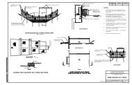
Iowa DOT SPR RB22-011 Aug 2012Project DetailsProcess Overview:The following is a list <strong>of</strong> the step-by-step tasks needed <strong>to</strong> complete this project:• Pre-Mission Planning• Targeting & Control• On-Site Planning & Safety• Scan Data Acquisition• Trajec<strong>to</strong>ry Processing & <strong>Report</strong>ing• Scan Data Processing, Adjustment &<strong>Report</strong>ing• LAS Data & Image Export• LAS Data Q/C & Refinement• Data Extraction• CAD Formatting• DTM Development• <strong>Final</strong> Product Delivery<strong>Scanning</strong> with Traffic ControlScan Targets:During the week <strong>of</strong> August 15, 2011, IowaDOT survey staff set tape targets for use in themobile scanning process. The 37 targets,shown as red triangles project overviewimage, were set in the both the right and lefthandshoulders <strong>of</strong> I-35 and IA 92, as well asalong the five ramps within the project limits.The targets were made from 4” temporarypavement marking tape with the legs <strong>of</strong> thetargets set at 2’ in length. The coordinates <strong>of</strong>a point set in<strong>to</strong> the pavement at the tip <strong>of</strong> thetarget were collected for use in dataprocessing.<strong>Mobile</strong> <strong>Scanning</strong> TargetProject Control:The horizontal datum for this survey is the North American Datum <strong>of</strong> 1983 (NAD83/1996).The vertical datum is the North American Vertical Datum <strong>of</strong> 1988 (NAVD88). All units inthis survey are US Survey Feet, defined as exactly 39.37/12 feet per meter.<strong>Mobile</strong> scan data and trajec<strong>to</strong>ries were based on a GPS base station occupying controlmonument “G063” at the east end <strong>of</strong> the IA 92 bridge over I 35. Iowa South, State PlanePage 6 <strong>of</strong> 19
Iowa DOT SPR RB22-011 Aug 2012Coordinate values used were Y: 497,204.00, X:1,565,346.23, and an NAVD88 orthometricheight <strong>of</strong> 843.314’.Deliverable scan data was exported on Iowa South State Plane Coordinate then transformed <strong>to</strong>Local Project Plane (LPP) values using the following equations:LPP y = [(State Plane y – 513,358.35) * 1.000086224] + 513,358.35LPP x = [(State Plane x – 1,563,703.57) * 1.000086224] + 1,563,703.57Data Acquisition:<strong>Scanning</strong> EquipmentR.E.Y.’s Riegl VMX-250 mobile scanning system was used for data acquisition. The VMX-250 system consists <strong>of</strong> the following:• 2 – Riegl VQ-250 line scanners• 2 – Riegl CS6 5 MPx Cameras• Applanix POS LV V4 Model 510 position and orientation system (IMU)• Trimble BD960 GNSS receiver• Trimble Zephyr Model 2 GNSS Antenna• Applanix Distance Measurement Indica<strong>to</strong>r (DMI)• Riegl Control Unit (CU)Page 7 <strong>of</strong> 19
Iowa DOT SPR RB22-011 Aug 2012Specifications for Riegl VMX-250 System:Page 8 <strong>of</strong> 19
Iowa DOT SPR RB22-011 Aug 2012Specifications for Applanix POS LV V4 Model 510 INS:Equipment Configuration:The log rate <strong>of</strong> the onboard GPS is fac<strong>to</strong>ry set at 5 Hz, which is supplemented by the IMUproviding vehicle and sensor position and orientation updates at a rate <strong>of</strong> 200 Hz. Eachscanner was configured for a measurement rate <strong>of</strong> 300 kHz (600 kHz combined). The scanvehicle travelled at an average speed <strong>of</strong> 40 mph, varying between 35 and 45 mph. Variation <strong>of</strong>the speed during acquisition assists in reducing IMU drift which tends <strong>to</strong> occur when constantdirection, pr<strong>of</strong>ile and speed are maintained over a period <strong>of</strong> time. At this speed andmeasurement rate, point density on the roadway surface ranges from approximately 600points/m2 at 20 feet from the sensors, <strong>to</strong> over 2,300 points/m2 along the trajec<strong>to</strong>ry line, on asingle pass.Two passes were made on each roadway, including ramps, for redundancy and increasedpoint density. A combination (or mosaic) <strong>of</strong> adjacent parallel passes are used for dataextraction.Scan data was acquired using Riegl’s RiACQUIRE s<strong>of</strong>tware, version 1.4.5 RiACQUIRE isinstalled on the Control Unit, and controls the laser sensors and INS data acquisition. At theend <strong>of</strong> the acquisition mission, the INS and scan data is immediately transferred <strong>to</strong> a lap<strong>to</strong>p or<strong>of</strong>fice workstation.Page 9 <strong>of</strong> 19
Iowa DOT SPR RB22-011 Aug 2012Scan Processing:• Vehicle Trajec<strong>to</strong>ry ProcessingTrajec<strong>to</strong>ry processing was performed using Applanix’s POSPac MMS version 5.3,Service Pack 3. Two base stations were fixed at their NAD83 (NAD83/1996) latitude andlongitude. Base station ellipsoid heights were fixed at their Geoid 09 modeled values,based upon their NAVD88 orthometric heights.Two methods <strong>of</strong> processing are available within the POSPac MMS suite, tightly or looselycoupled. In both solutions, the data is processed in both forward and backward directions<strong>to</strong> produce the optimal solution, smoothing the effect <strong>of</strong> GPS outages and otheraberrations in the data. In a tightly coupled solution the IMU data is used <strong>to</strong>gether withthe GPS data <strong>to</strong> produce a smoothed best estimate <strong>of</strong> trajec<strong>to</strong>ry (SBET) for the scanvehicle. During a complete GPS outage, the IMU data is not only used <strong>to</strong> carry thevehicle position, but also assists in regaining the GPS integer count when satellitereception is regained. A successful tightly coupled solution is always preferable <strong>to</strong> aloosely coupled solution. However, the tightly coupled solution currently only uses GPSdata and does not make use <strong>of</strong> any GLONASS data that may be available. The looselycoupled solution does make use <strong>of</strong> GLONASS data if available. However, the vehicletrajec<strong>to</strong>ry is based entirely upon the GNSS derived trajec<strong>to</strong>ry, with IMU data only beingused during a GNSS outage and in determining the orientation <strong>of</strong> the scanner. Thissolution would be used in the event that GPS data was <strong>of</strong> insufficient quality and a tightlycoupled solution was not possible. For these reasons, GPS and GLONASS data for boththe mobile platform and the base station(s) are always logged as a backup.Vehicle trajec<strong>to</strong>ries from the primary base station processed successfully as tightlycoupled solutions. As such, the backup base station data was not used in this survey.Trajec<strong>to</strong>ry quality reports are contained in Section 2 <strong>of</strong> this report. The reports arepresented as an overall trajec<strong>to</strong>ry, and further broken down by individual scan collectionsegments.• Scan Data ProcessingScan data was processed using Riegl’s RiPROCESS s<strong>of</strong>tware, version 1.4.15. InRiPROCESS raw scan data is time-matched with the SBET <strong>to</strong> produce trajec<strong>to</strong>ry-based,geo-referenced scan data. Scan records are typically collected in one mile segments on themainline, and for each ramp individually <strong>to</strong> allow for manageable data file sizes.Initially, each scan Record, consisting <strong>of</strong> overlapping data from Scanner 1 and Scanner 2,is compared by laser data height differencing. The laser difference range was set <strong>to</strong> +2 cm<strong>to</strong> -2 cm. This allows visual verification that scan records contain readily usable data.The image below-left, showing a rainbow effect <strong>of</strong> the laser differencing, is an example <strong>of</strong>data that is “scissored”. This scan record would be rejected in favor <strong>of</strong> the data in thesecond image below-right. Laser differencing in the second image indicates overlappingscan data is well within 2cm, and closer <strong>to</strong> 5mm <strong>of</strong> relative difference. Further processingis required for those scan Records that show laser differencing approaching and in excessPage 10 <strong>of</strong> 19
Iowa DOT SPR RB22-011 Aug 2012<strong>of</strong> 2cm. (The images below are examples only, and are not representative <strong>of</strong> the datacollected on this project.)Scan Data Adjustment is a <strong>to</strong>ol in RiPROCESS <strong>to</strong> improve the calibration <strong>of</strong> the systemand the relative fit <strong>of</strong> the scan data. It allows the adjustment <strong>of</strong> several parameters such asthe orientation and position <strong>of</strong>fsets per laser data, per laser device, per navigation deviceand <strong>of</strong> the trajec<strong>to</strong>ry. Scan Data Adjustment is an iterative process whose results are basedon interactive judgment and decisions as <strong>to</strong> when scan Records have reached their optimalrelative adjustment.Experience has proven that over-adjusting scan data is possible and scan data relativitycan be degraded. Allowing <strong>to</strong>o much freedom in the Roll, Pitch and Heading adjustmentparameters can cause initially good data <strong>to</strong> drift out <strong>of</strong> <strong>to</strong>lerance.In RiPROCESS scan data was adjusted using a two-step process. The first process iscloud-<strong>to</strong> cloud adjustment using a routine called “Manual Tie Planes”. Overlapping scandata is allowed <strong>to</strong> “float” within certain defined parameters. This reduces horizontal andvertical <strong>of</strong>fsets between overlapping data, while improving the data’s absolute positionbased on the initial trajec<strong>to</strong>ries. Second, the resulting data was related <strong>to</strong> the scan targetsby editing the position and orientation file by use <strong>of</strong> “Manual Tie Objects”. This methodallows the trajec<strong>to</strong>ries, and dependent scan data, <strong>to</strong> adjust <strong>to</strong> the field surveyedtransformation and validation points.At the conclusion <strong>of</strong> adjustment in RiPROCESS, LAS 1.2 files were exported, in IowaSouth coordinates and NAVD88 elevations, for further analysis and final adjustment inMARS Explorer 7 and TopoDOT.• LAS File Transformation and AdjustmentPage 11 <strong>of</strong> 19
Iowa DOT SPR RB22-011 Aug 2012MARS Explorer 7, from Merrick & Company, was used for transforming the LAS filesfrom Iowa South coordinates <strong>to</strong> Local Project Plane (LPP) coordinates. This exercise wasalso used <strong>to</strong> combine Scanner 1 and Scanner 2 data in<strong>to</strong> composite LAS files for eachpass. Additionally, if necessary, MARS can be used <strong>to</strong> apply final X,Y, or Z shifts <strong>to</strong> theLAS data. Shifts in the X and Y directions are based on visual observation <strong>of</strong> the scantargets <strong>to</strong> the surveyed value <strong>of</strong> the point. Shifts in the Z direction are determined in anau<strong>to</strong>mated fashion by comparing a TIN face <strong>to</strong> the surveyed value <strong>of</strong> the scan target point.The final step is developing accuracy reports, by comparing the scan targets <strong>to</strong> thefinished point cloud data. For final accuracy reporting we used TopoDOT’s “ControlPoint <strong>to</strong> Data Analysis”, which compares the Z <strong>of</strong> the scan target point <strong>to</strong> an average Z <strong>of</strong>all scan data within a user defined radius. The TopoDOT Control Point <strong>to</strong> Data Analysis<strong>Report</strong> is contained in Section 3 <strong>of</strong> this report. The purpose <strong>of</strong> the report is <strong>to</strong> illustrate theoverall accuracy <strong>of</strong> the final point cloud data, relative <strong>to</strong> the project control. Below is asummary <strong>of</strong> the relative accuracy’s between the scan targets and the point clouds.• MTLS Feature Extraction & Formatting<strong>Final</strong> LAS files were loaded in<strong>to</strong> Certainty 3D’s TopoDOT (version 4.3.12.4) product.TopoDOT is a high performance Micro<strong>Station</strong> (version 8i, Select Series 2) application forextracting 3D deliverable <strong>to</strong>pography, planimetrics and models from point clouds,calibrated images and related 3D data.In real-time, 3D line and point features were traced and draped directly in<strong>to</strong> theappropriate Iowa DOT seed file, using the Iowa DOT specific color table, line-stylelibrary and cell library. Upon completion <strong>of</strong> feature extraction, no CAD translations orformatting is required.Adjusted mobile LiDAR hard surface data typically lies within a band <strong>of</strong> points rangingfrom .02’ <strong>to</strong> 0.08’ in thickness. The draping method used for developing data on hardsurfaces is taking the average elevation <strong>of</strong> all points within a user defined radius for thePage 12 <strong>of</strong> 19
Iowa DOT SPR RB22-011 Aug 2012point being extracted. The radius used is dependent on the density <strong>of</strong> the points in the area<strong>of</strong> the feature being delineated.The final step in the delivery process was developing a GEOPAK surface (TIN). Theprocess we elected <strong>to</strong> use for this project is <strong>to</strong> first create an InRoads surface (DTM) fromthe 3D graphic elements we compiled in Micro<strong>Station</strong> from the LAS files, then export <strong>to</strong>GEOPAK TIN format by use <strong>of</strong> the data acquisition feature in Micro<strong>Station</strong>. Both TINand DTM formats were delivered <strong>to</strong> the Iowa DOT.Note: Supplemental survey data will typically be required in areas <strong>of</strong> ground cover andvegetation. Also, since the mobile scanner is a line-<strong>of</strong>-sight instrument, if it can’t beseen with the naked eye, chances are it will need <strong>to</strong> be surveyed conventionally.Again, areas subject <strong>to</strong> flat grazing angles may require supplemental surveys, viaaerial mapping, field surveys or airborne LiDAR. In areas <strong>of</strong> vegetation, theadvantage airborne LiDAR has over ground-based LiDAR is the nearlyperpendicular perspective the airborne sensors have <strong>to</strong> the ground. This allows forbetter penetration which results in more “last returns” <strong>of</strong>f the bare earth surface.However, airborne data is typically not as accurate on hard surfaces as groundbaseddata due <strong>to</strong> range, altitude and attitude (roll, pitch, and yaw) <strong>of</strong> the aircraft.Data sets can be seamlessly merged using GEOPAK or InRoads surface creation<strong>to</strong>ols/techniques as well as the Data Acquisition functionality in Micro<strong>Station</strong>®.Data from different sources should reside in different models in the Micro<strong>Station</strong>file, so the data source can be followed when determining which data is best in agiven area. Supplemental survey data will typically be required in areas <strong>of</strong> groundcover and vegetation. Also, since the mobile scanner is a line-<strong>of</strong>-sight instrument, ifit can’t be seen with the naked eye, chances are it will need <strong>to</strong> be surveyedconventionally. Again, areas subject <strong>to</strong> flat grazing angles may requiresupplemental surveys, via aerial mapping, field surveys or airborne LiDAR. Inareas <strong>of</strong> vegetation, the advantage airborne LiDAR has over ground-based LiDARis the nearly perpendicular perspective the airborne sensors have <strong>to</strong> the ground.This allows for better penetration which results in more “last returns” <strong>of</strong>f the bareearth surface. However, airborne data is typically not as accurate on hard surfacesas ground-based data due <strong>to</strong> range, altitude and attitude (roll, pitch, and yaw) <strong>of</strong> theaircraft.Data sets can be seamlessly merged using GEOPAK or InRoads surface creation<strong>to</strong>ols/techniques as well as the Data Acquisition functionality in Micro<strong>Station</strong>®.Data from different sources should reside in different models in the Micro<strong>Station</strong>file, so the data source can be followed when determining which data is best in agiven area.Page 13 <strong>of</strong> 19
Iowa DOT SPR RB22-011 Aug 2012ResultsThe following is a summary <strong>of</strong> <strong>to</strong>pics discussed at the completion <strong>of</strong> the project.Data S<strong>to</strong>rage and Computer IssuesComputing and s<strong>to</strong>rage requirements need <strong>to</strong> be separated in<strong>to</strong> two distinct categories;Data processing and extraction, versus end-user usage, and tend <strong>to</strong> be s<strong>of</strong>tware dependent.Delivered LAS and image files for this project <strong>to</strong>taled almost 31GB.Data ProcessingAcceptable performance can be achieved with modest hardware such as a dual-coreprocessor (hyper-threading a plus), 32-bit operating system, 4GB RAM, mid-levelgraphics board, 500GB internal hard drive and the ability <strong>to</strong> attach external drives viaeSATA or USB 3.0 interfaces when needed. However, higher-end hardware does achievemeasurable performance gains and reduced time expenditure. The size <strong>of</strong> the project datafiles is subject <strong>to</strong> many variables such as scan density, vehicle travel speed, etc. The RieglVMX-250 produces approximately 500 <strong>to</strong> 700MB <strong>of</strong> raw scan data per mile <strong>of</strong> scanningwhen set for a scan density <strong>of</strong> 600,000 points per second and travelling at 40 mph. Theraw scan data is s<strong>to</strong>red in a compacted format. There is nearly a 6-fold increase in the size<strong>of</strong> the scan data after post-processing. Camera data, when enabled, producesapproximately 900MB <strong>of</strong> imagery data per mile using a 2-camera, 5 megapixel system.Data ExtractionData extraction is performed using the final, adjusted LAS files. The Riegl VMX-250system, configured as described, produces approximately 1.0 <strong>to</strong> 1.4GB <strong>of</strong> LAS data permile <strong>of</strong> scan. Extraction <strong>to</strong>ols are capable <strong>of</strong> segmenting the LAS data in<strong>to</strong> moremanageable working-file sizes. Experience will determine the maximum manageabledata-set size for a particular hardware platform. Systems are capable <strong>of</strong> loading one mile<strong>of</strong> LAS data at a time while maintaining acceptable performance during extraction.Clipping <strong>of</strong> the LAS data outside <strong>of</strong> the area <strong>of</strong> interest allows for longer, wider ormultiple segments <strong>to</strong> be loaded. The primary limitation in our environment is the fact thatMicro<strong>Station</strong>, at this time, is still 32-bit platform. Certain Micros<strong>of</strong>t Windows systemsettings will allow Micro<strong>Station</strong> <strong>to</strong> access more than 2GB RAM, but Micro<strong>Station</strong>’saccess <strong>to</strong> this additional memory is via way <strong>of</strong> memory paging. When Micro<strong>Station</strong> <strong>of</strong>fersa 64-bit platform; manageable data set sizes as well as overall performance shouldincrease.End-User UsageThe typical finished products from a scan mission are the CAD design files and the LASpoint cloud files. The CAD files typically produced are indistinguishable fromconventionally derived products. Hardware platforms currently providing satisfac<strong>to</strong>ryperformance will suffer no adverse impacts from the incorporation <strong>of</strong> scan-derivedproducts. Several free and commercial utilities are available for the viewing <strong>of</strong> the LASfiles. One example is the free-ware s<strong>of</strong>tware viewer Quick Terrain Reader, developed byJohns Hopkins University's Applied Physics Lab. Suitable performance is achieved usingthe lower-end systems described above, although larger models will see substantiallyincreased performance when viewed on higher end, 64-bit platforms with greater than4GB RAM and pr<strong>of</strong>essional grade graphics boards.Page 14 <strong>of</strong> 19
Iowa DOT SPR RB22-011 Aug 2012AccuracyThe data acquiredthrough the MTLS anddata processing meetsthe Iowa DOTspecifications forengineering survey.The adjacent tablesummarizes theaccuracy <strong>of</strong> the 76control points thatwere covered by thescanning.The following table is an example <strong>of</strong> the accuracy for 16 <strong>of</strong> the 76 control points.Page 15 <strong>of</strong> 19
Iowa DOT SPR RB22-011 Aug 2012A comparison was done between 1823 points on the pavement that were surveyed byIowa DOT staff using a <strong>to</strong>tal station and the same points generated through the MTLSprocess. The results <strong>of</strong> that comparison are shown below.1823 <strong>Total</strong> Number <strong>of</strong> Points497 Points Below the TIN Surface1325 Points Above the TIN Surface1 Points Equal <strong>to</strong> the TIN SurfaceSum <strong>of</strong> the Elevation Difference Squared = 8.8101Average <strong>of</strong> Elevation Difference Squared = 0.0048Root Mean Square Error = 0.0695National Standard for Spatial Data Accuracy (NSSDA) = 0.1363Points PASS the 95% confidence test based on 1.96 Chi Square Value.The difference in the 1823 points compared is shown below.Page 16 <strong>of</strong> 19
Iowa DOT SPR RB22-011 Aug 2012The following is a typical example <strong>of</strong> a cross section showing the surface resulting from theoriginal Iowa DOT surface and the surface produced through the MTLS process. The results<strong>of</strong> the scanning are very good on the roadway pavement.Page 17 <strong>of</strong> 19
Iowa DOT SPR RB22-011 Aug 2012Survey Time <strong>Comparison</strong>:The hours listed below are approximate but are useful in comparing time used <strong>to</strong> capture theroadway data using MTLS and a <strong>to</strong>tal station survey.MTLS:The number <strong>of</strong> hours per work task for all activities for the MTLS process:Planning22 hoursTravel & Logistics34 hoursOn-Site Planning16 hoursScan Data Acquisition16 hoursOn-Site Pre-Processing12 hoursTrajec<strong>to</strong>ry Processing & <strong>Report</strong>ing8 hoursScan Data Processing, Adjustment & <strong>Report</strong>ing 16 hoursLAS Data& Image Export12 hoursLAS Data Q/C & Refinement16 hoursData Extraction140 hoursCAD Formatting16 hoursDTM Development6 hours<strong>Final</strong> <strong>Report</strong>s24 hoursData Assembly & Delivery8 hours<strong>Total</strong> 318 hours<strong>Total</strong> <strong>Station</strong> Survey:All field and <strong>of</strong>fice activities<strong>Total</strong> 260 hoursBenefitsThe following is a listed <strong>of</strong> MTLS process and product benefits:• The density <strong>of</strong> data points collected is significantly greater than traditional survey andprovides the highway designer with a much better understanding <strong>of</strong> the existingroadway and associated features.• Improved safety for the survey crew members by significantly reducing the amount <strong>of</strong>time they need <strong>to</strong> send in close proximity <strong>to</strong> the traveling public.• Improved safety <strong>to</strong> the traveling public by reducing the amount <strong>of</strong> time that surveyvehicles are present near the roadway as well as reducing the possible distraction <strong>of</strong>survey activities.• The accuracy <strong>of</strong> the MTLS products meets the requirements for highway design.• The rate <strong>of</strong> data collection in the field is much greater than traditional methods.• More Data Features like Super StructuresPage 18 <strong>of</strong> 19
Iowa DOT SPR RB22-011 Aug 2012ChallengesThe following is a list <strong>of</strong> challenges <strong>to</strong> overcome with the MTLS process:• Development <strong>of</strong> specifications, similar <strong>to</strong> those found in Chapter 15 <strong>of</strong> the CaltransSurveys Manual, will be essential for the Iowa DOT <strong>to</strong> receive data meeting the needs<strong>of</strong> highway and bridge designers.• Advancement in the s<strong>of</strong>tware that aid highway designers in fully utilizing the fullbenefits on the MTLS produced data.Summary/ImplementationWith the success <strong>of</strong> this project, it is anticipate that additional projects will be scanned forthe Iowa DOT for use in the development <strong>of</strong> highway improvement projects.Page 19 <strong>of</strong> 19