FLH PDDM Chapter 9 - Eastern Federal Lands Highway Division
FLH PDDM Chapter 9 - Eastern Federal Lands Highway Division
FLH PDDM Chapter 9 - Eastern Federal Lands Highway Division

Create successful ePaper yourself
Turn your PDF publications into a flip-book with our unique Google optimized e-Paper software.
TABLE OF CONTENTS9.4 PS&E DEVELOPMENT (continued) PageB. Intersection Design ....................................................... 9-581. Intersection Types2. Design Vehicle3. Alignment4. Sight Distance5. Channelization6. Traffic Islands7. Left-Turn Lanes8. Right-Turn LanesC. Earthwork Design ........................................................ 9-711. Clearing and Grubbing2. Removal of Structures and Obstructions3. Classification of Roadway Excavation4. Shrink and Swell Factors5. Design Cut and Fill Slopes6. Slides7. Balancing Earthwork8. Haul9. Mass Diagram10. Computing Structural Excavation Quantities11. Subgrade Treatment12. Roadway Obliteration13. Design Steps Using IHDSD. Earth Retaining Structures ................................................. 9-781. Design considerationsa. Determination of Needb. Alternative Wall Systemsc. Design Guidelinesd. Selection of Wall Typese. Retaining Wall Systems2. Contracting Procedures3. Consideration of New Retaining Wall Systemsii
TABLE OF CONTENTS9.4 PS&E DEVELOPMENT (continued) PageE. Drainage Design .......................................................... 9-891. Channels and Ditches2. Culverts3. Downdrains and Pipe Anchors4. Catch Basins and Inlets5. Storm Drains/Storm Sewers6. Underdrains and Horizontal Drains7. Riprap/Slope Protection8. Energy Dissipators and Outlet Basins9. Erosion ControlF. Other Design Elements .................................................... 9-931. <strong>Highway</strong> Lighting2. Fencing3. Cattleguards4. Pedestrian Facilities5. Parking Areas6. Accommodation of the Disabled7. <strong>Lands</strong>caping and Roadside DevelopmentG. Right-of-way and Utilities ................................................. 9-1051. Right-of-way2. Utilities3. Railroad Encroachments4. Railroad Grade Crossings5. Material Source Reclamation PlansH. Reviews ............................................................... 9-127I. Plans . ................................................................ 9-1291. Bridge Plans2. Standard DrawingsJ. Engineer's Estimate ...................................................... 9-1311. Computation of Quantities2. Computation of Contract Time3. Development of Pricesiii
TABLE OF CONTENTS9.4 PS&E DEVELOPMENT (continued) PageK. Specifications ........................................................... 9-1451. Types of Specifications2. Developing Special Contract Requirements3. Writing Special Contract RequirementsL. Contract Assembly ....................................................... 9-1539.5 APPROVALS ............................................................ 9-1549.6 STANDARD FORMAT .................................................... 9-155A. Plans1. Format2. Drafting Standards3. Organization of Plansa. Title Sheetb. Typical Sectionsc. Summary of Quantitiesd. Tabulation of Quantitiese. Plan and Profilef. Bridgesg. Drainage Facilitiesh. Traffic Control Plani. Standard Drawings, Standard Details, and Special Detailsj. Environmental Mitigationk. Cross Sectionsl. Contiguous ProjectsB. SpecificationsC. EstimateD. PS&E Package9.7 DIVISION PROCEDURES ................................................. 9-166EXHIBITSiv
FigureLIST OF FIGURESPage9-1 Superelevation Transition on Short TangentsBetween Broken-Back Curves ................................................. 9-199-2 Superelevation Transitions for Broken-Back Curves ................................ 9-209-3 Determining Flat Sections Between ReversingCurves with Short Tangents ................................................... 9-219-4 Reserved9-5 Lateral Clearance for Stopping Sight Distance ..................................... 9-319-6A Desirable Horizontal Stopping Sight Distance ..................................... 9-329-6B Minimum Horizontal Stopping Sight Distance ..................................... 9-339-7 Determining Low Points on Vertical Curves with Unequal Grades ..................... 9-349-8 Eliminating Broken-Back Vertical Curves ........................................ 9-369-9 Typical Road Cross Section Elements ........................................... 9-399-10 Typical Cut Slope End Treatment .............................................. 9-429-11 Falling Rock Control ........................................................ 9-469-12 Rolling Rock Control ........................................................ 9-479-13 Serrated Slopes ............................................................. 9-499-14 Right Turn Deceleration Lanes for Non-controlled Access <strong>Highway</strong>s ................... 9-519-15 Right Turn Acceleration Lanes for Non-controlled Access <strong>Highway</strong>s ................... 9-529-16 Slow Moving Vehicle Turnout ................................................. 9-549-17 Left Turn Storage Guidelines for Unsignalized TwoLane <strong>Highway</strong> Intersections ................................................... 9-659-18 Left Turn Storage Lengths for Unsignalized TwoLane <strong>Highway</strong> Intersections (60 km/h) ........................................... 9-669-19 Left Turn Storage Lengths for Unsignalized TwoLane <strong>Highway</strong> Intersections (80 km/h) ........................................... 9-679-20 Left Turn Storage Lengths for Unsignalized TwoLane <strong>Highway</strong> Intersections (100 km/h) .......................................... 9-689-21 Right Turn Lane Guidelines ................................................... 9-699-22 Right Turn Pocket or Taper ................................................... 9-70v
LIST OF TABLESTablesPage9-1 Design Standards ............................................................ 9-39-2 Minimum Signing for Curves and Turns .......................................... 9-69-3 Example Listing of a Determination ofSuperelevation Rates ........................................................ 9-239-4 Sight Distance Standards ..................................................... 9-299-5 Effects of Grades on Stopping Sight Distance ..................................... 9-309-6 (K) Values for Determining Lengths of Vertical Curves ............................. 9-379-7 Foreslope Ratios ............................................................ 9-419-8 Desirable and Maximum Slopes ................................................ 9-449-9 Intersection Design Vehicle ................................................... 9-599-10 Sight Distance Adjustment Factor .............................................. 9-609-11 Sight Distance for Turning Vehicles ............................................ 9-619-12 Offset Distances for Barrier Curb ............................................... 9-629-13 Additional Left Turn Storage for Trucks atUnsignalized Two-Lane <strong>Highway</strong> Intersections .................................... 9-649-14 Guidelines for Railroad Crossing Protection ..................................... 9-1249-15 Correct Usage of Words and Phrases ........................................... 9-1509-16 Lettering Sizes and Styles .................................................... 9-157vi
CHAPTER 9 - HIGHWAY DESIGN9.1 GENERALThis chapter provides policies, procedures, and methods for developing and documenting the design ofhighways. It also includes the preparation of plans, specifications and estimates (PS&E) for new highwayconstruction, reconstruction and RRR (Resurfacing, Restoration and Rehabilitation) improvements.A. Role of the Designer. The designer shall gather all the engineering and environmental input requiredto provide a complete and acceptable PS&E assembly. The PS&E package depicts the commitments madeduring the planning, programming, and project development stages.The designer is responsible for applying guidance from <strong>Chapter</strong> 8, Safety and <strong>Chapter</strong> 9, <strong>Highway</strong> Design.In addition, the following named chapters provide information on collecting background data for thedevelopment of the PS&E.<strong>Chapter</strong> 2 - Planning and Programming. Information on the planning and programming functions,interagency agreements, and general data on the scope and funding levels for individual projects arecovered in this chapter.<strong>Chapter</strong> 3 - Environment. This chapter provides information about environmental requirements andpublic involvement. Environmental documents will include commitments made for mitigation andpublic acceptance of the project. The designer will review all environmental documents forcommitments made during the conceptual studies phase that affect development and construction of theproject or operation of the highway following construction. Any proposed deviation from themitigating measures and commitments must be coordinated with the <strong>Division</strong> environmental unit andaffected resource agencies.<strong>Chapter</strong> 4 - Conceptual Studies. These studies result in a recommended roadway location and basicdesign criteria for a facility. Such studies are generally developed in conjunction with theenvironmental process. Conceptual studies generally include significant input from the owner agencyand from other interested parties.<strong>Chapter</strong> 5 - Survey and Mapping. The survey unit provides information on the field survey, property,utility locations, and related data. The data collected provides topographic maps, site maps, right-ofwayand utility plats, and base information for developing the design.<strong>Chapter</strong> 6 - Geotechnical. The geotechnical unit provides subsurface data and recommendations forearthwork slopes, materials, and pavement structure design. When applicable the report includesfoundation design for bridges, retaining walls, and other structures, along with landslides andsubsurface water information.<strong>Chapter</strong> 7 - Hydrology/Hydraulics. The hydraulics unit provides runoff data for roadside drainagedesign. This unit also provides data to the structural unit (for major structures) and designs majorhydraulic structures and special water resource features.<strong>Chapter</strong> 10 - Structural Design. The structural unit designs bridges, major retaining structures, andspecial structural elements. The unit will provide complete structural plans, proposed specifications,and an estimate of cost for incorporation into the PS&E package.9 - 1
9.1.B. Design Standards.B. Design Standards. Guidelines for geometric design have changed significantly over the years.Today's emphasis is on balancing the factors of safety, economy, environmental concerns, energyconservation, and social effects with the traditional concerns for volume and speed.The FHWA has adopted policies and standards for <strong>Federal</strong>-aid highway design that recognize all theseprecepts. They are listed in 23 CFR 625 and supplemented in the FAPG. These standards basically adoptAASHTO policy and are applicable to <strong>Federal</strong> <strong>Lands</strong> <strong>Highway</strong> design.Other <strong>Federal</strong> agencies, States and many local highway agencies have adopted standards implementingAASHTO policy with supplemental and clarifying criteria.Table 9-1 lists the principle <strong>FLH</strong> programs and corresponding design standards. The appropriate standardsare normally identified in the planning, programming, or conceptual studies document for the project.Occasionally the designer will need to determine which standards are approved for use on a specificproject. The appropriate unit chief should be consulted.9 - 2
9.1.B. Design Standards. (continued)The design criteria shown in Table 9-1 represent both desirable and minimum standards. Each designshould be evaluated on the basis of desirable design criteria for the safest overall design.Cost, social and environmental factors often require standards that are less than desirable. This isparticularly true for RRR projects. When these factors dictate design elements resulting in less thanminimum standards, the designer must evaluate the consequences and document the decision inaccordance with Section 9.1.B.2., Design Exceptions.Table 9-1Design Standards*Type of RoadwayForest <strong>Highway</strong> and Public <strong>Lands</strong> <strong>Highway</strong>sApplicable Standards23 CFR 625 and FHWA approved State or localstandards.National Park Roads and Parkways NPS standards (1984) and 23 CFR 625.Indian Reservation Roads25 CFR 170, BIA design manual and23 CFR 625.FAA Roads 23 CFR 625.BLM Access RoadsDefense Access RoadsFAPG G6090.13 and BLM Manual,Section 9113 - Roads.23 CFR 625 or FHWA approved State or localstandards.FS Roads and Trails FS Handbook (FSH 7709.11).ERFOStandards determined by classification ofhighway to be repaired or reconstructed. (SeeERFO Manual)* When there is a conflict between agency standards and 23 CFR 625, the design criteria should be mutually resolved with the client agency.9 - 3
9.1.B. Design Standards. (continued)1. Policy. It is <strong>FLH</strong>O policy to use approved standards for the design of projects funded from thehighway trust fund. For projects funded through owner-agency appropriations, the owner-agency'sstandards apply, provided they are consistent with good engineering practice.a. Design Criteria. The 1994 AASHTO publication, A Policy on Geometric Design of <strong>Highway</strong>s andStreets, (also known as the Green Book) is the principle source for highway design criteria. Supplementsto the Green Book include other AASHTO and technical publications adopted as acceptable criteria andother <strong>Federal</strong>, State and local specifications for use on their roads. These acceptable supplements arereferenced throughout this manual.b. Design Speed. A principle element in establishing design criteria is the selection of the design speedfor the facility. The design speed should be consistent with the speed the driver expects. It should belogical for the topography, adjacent land use, and type of highway. The design speed must equal or exceedthe posted or regulatory speed limit of the completed facility. The Green Book, pages 62 to 68, explainsthe philosophy of design speed. In most instances, the owner agency has the authority to establish theposted speed for the facility. When necessary, regulatory limits should be recommended to the owneragencyto provide guidance in setting posted speeds. However, when system-wide statutory speed limitsprevail (such as the national 55 mph limit) they mandate posted speed.c. RRR Projects. The design policy for RRR projects is the same as for new construction; however,designing these projects to approved standards may not be possible. Alternative actions should beanalyzed when environmental concerns, social impacts, extraordinary costs or limited funds preventconstruction to full standards. Analysis should include consideration of adjacent highway sections and therelationship to future improvements, as well as existing conditions. When the analysis concludes thatapproved standards are not practical, the designer shall document each exception to the standards asoutlined in Section 9.1.B.2.2. Design Exceptions. When approved standards are not obtained, the designer must document allexceptions. There are 13 principle design elements that are considered controlling criteria and whichrequire documentation each time they are unobtainable:(1) Design speed.(2) Lane width.(3) Shoulder width.(4) Bridge width.(5) Structural capacity.(6) Horizontal curvature.(7) Vertical curvature.(8) Gradient.(9) Stopping sight distance.(10) Cross slopes.(11) Superelevation.(12) Horizontal clearance to structures (tunnels & bridge underpasses)(13) Vertical clearance.In addition to these controlling criteria, the designer should document other elements of operationalefficiency or safety not meeting standards. Exhibit 9.1 presents a sample format for documenting designexceptions on a project.9 - 4
9.1.B. Design Standards. (continued)This documentation supporting the design exception decision shall become a part of the PS&E packagepresented to the owner agency.Documentation of design exceptions should include an explanation of the conditions prohibiting fullstandards and a description of the mitigating measures proposed to maximize operation and safety of thefacility.3. Mitigating Design Exceptions. Tort liability is a major concern of the Government. The designermust ensure that the design process is in compliance with all applicable standards.The exception to standards outlined in <strong>FLH</strong>M 3-C-2 permits the designer to vary the controlling criteriawhen alternatives merit precedence over standards.The project plans should include curve signs, turn signs, and advisory speed plates for mitigation purposeswhen posted limits cannot be reduced. The MUTCD specifies installation of advisory speed platesfollowing a determination of the safe speed by accepted traffic engineering procedures.An accepted field method of determining safe speed for horizontal curvature uses a slope meter, morecommonly referred to as the ball bank indicator. When advisory speed plates are warranted, the projectengineer should be provided with a listing of curve signs, turn signs, and advisory speed plates needed forthe project as determined by theoretical design speed criteria. Signing normally appears on the plans butoccasionally supplemental studies dictate the need to forward additional data to the field.The project engineer verifies the safe speed of the curves in question using the ball bank indicator or otheraccepted traffic engineering procedures. The engineer can contact a local State, county, or municipaltraffic engineer to arrange for a speed determination if a ball bank indicator is not available on a projectvehicle. See pages 143-145 and Figure III-4 in the Green Book for a discussion on the relationship of ballbank readings and safe speeds. Also see Figure 9-4, Safe Speeds.Table 9-2 establishes signing requirements for curves and turns.Some agencies have criteria other than what is shown in Table 9-2. The designer should check theagencies' standards for conflicts between the two and use the more conservative signing criteria.Determining the appropriate standards to be used for roadway lane and shoulder widths is sometimesdifficult. In some cases, the project may be the only improvement on a route for many years. In othercases, the maintaining authority may have a policy that only resurfacing projects will be applicable to aroute to use available funding for higher priority transportation facilities. In these instances, thecompatibility with adjacent sections of the highway may be the governing criteria. When compatibilitywith adjoining roads is the controlling factor, a design exception is appropriate.Extraordinary cost or adverse environmental impacts could also result in design exceptions. When thehighway operating agency's approved transportation plan specifies less than the standard widths for a route,this width requires documentation as a design exception.The remaining controlling criteria are usually limited to site specific locations. The designer must mitigatethese design exceptions through the normal design process.9 - 5
9.1.B. Design Standards. (continued)Some RRR projects cannot be surveyed cost effectively in enough detail to identify many of the exceptionsto the controlling criteria, such as super-elevation, grades, etc. These projects place considerable emphasison the engineering judgment of the designer. Any on-site study or field review for RRR projects shoulddocument any identifiable exceptions to standards.Table 9-21Minimum Signing for Curves and Turns2Safe Speed (km/h)PostedSpeed 30 40 50 55 60 70 80 90 100or lessMPH km/h60 100 TA TA TA CA CA CA C C55 90 TA TA TA CA CA C C50 80 TA TA TA CA C C45 70 TA TA TA C C40 60 TA TA T C35 55 TA T TA = Advisory Speed Plate30 50 T TC = Curve Warning Sign, Reverse Curve Sign25 40 T (or Winding Road Sign)20 30 T = Turn Sign, Reverse Turn Signor(or Winding Road Sign)lessNotes:1See MUTCD (Section 2C-4 and 2C-5).2Determine the safe speed by use of the ball bank indictor.9 - 6
9.1.C. Computer Aided Design and Drafting.C. Computer Aided Design and Drafting (CADD). Information on Computer Aided Design andDrafting is included in the <strong>Federal</strong> <strong>Lands</strong> <strong>Highway</strong> CADD Manual.9 - 7
9.2 GUIDANCE AND REFERENCESThe publications listed in this section provided much of the fundamental source information used in thedevelopment of this chapter. While this list is not all inclusive, the publications listed will provide thedesigner with additional information to supplement this manual.A Policy on Geometric Design of <strong>Highway</strong>s and Streets. AASHTO. 1994.<strong>Highway</strong> Capacity Manual. TRB Special Report No. 209. Transportation Research Board. 1985.Manual on Uniform Traffic Control Devices (MUTCD). DOT, FHWA. 1988.Traffic Control Devices Handbook. DOT, FHWA. 1983.Park Road Standards. U.S. Department of the Interior, National Park Service. 1984.Standard Specifications for Construction of Roads and Bridges on <strong>Federal</strong> <strong>Highway</strong> Projects (FP-96).DOT, FHWA. 1995.Standard Specifications for Structural Supports for <strong>Highway</strong> Signs, Luminaries and Traffic Signals.AASHTO. 1986.Guide for Development of Bicycle Facilities. AASHTO. 1991.A Policy on Design of Urban <strong>Highway</strong>s and Arterial Streets. AASHTO. 1973. (Out of Print).Railroad-<strong>Highway</strong> Grade Crossing Handbook. Report No. FHWA-TS-86-215, 1986.Intersection Channelization Design Guide. NCHRP 279.An Informational Guide for Roadway Lighting. AASHTO. 1984.A Guide of Accommodating Utilities Within <strong>Highway</strong> Right-of-Way. AASHTO. 1994.A Guide for Erecting Mailboxes on <strong>Highway</strong>s. AASHTO. 1994.Roadway Lighting Handbook. DOT, FHWA. 1978 (and addendum 1983).Americans with Disabilities Act (ADA) Accessibility Guidelines. Architectural and Transportation BarriersCompliance Board. 1994Roadside Design Guide. AASHTO. 1989A Guide to Standardized <strong>Highway</strong> Barrier Hardware. AASHTO-AGC-ARTBA. 1995Recommended Procedures for the Safety Performance Evaluation of <strong>Highway</strong> Features. NCHRP Report350. TRB. 1993Design Risk Analysis (Volume I and II). FHWA-FLP-91-001. FHWA. 19919 - 8
9.2 Guidance and References. (continued)Standard Practice for Use of the International System of Units (SI). The Modernized Metric System.E380-93. ASTM. 1993Trail Design Manual "Trails for the Twenty-First Century": Planning, Design, and Management Manualfor Multi-use Trails. Rails to Trails Conservancy, 1993Designing Safer Roads. TRB Special Report No. 214. Transportation Research Board. 1987.Horizontal Alignment Design Consistency for Rural Two-Lane <strong>Highway</strong>s. FHWA-RD-94-034. FHWA.19959 - 9
9.3 INFORMATION GATHERINGThe designer is directed to <strong>Chapter</strong> 4, Conceptual Studies, for information on scoping, background data,preliminary design standards, and mitigating measures before beginning detailed design activities.A. Design Study. A design study documents considerations and conclusions reached during thedevelopment of a project. Although it may not always result in a formal document, the study provides ahistory of the project from start to completion of the PS&E.When the designer has completed the PS&E, the following applicable data should be available in the files:Project Description:- Description of existing conditions.- Comparison of proposed work with "no build" alternative.- Extent of selection and examination of alternatives.- Identification of deficiencies with costs to correct.- Design parameters used.Evaluation of any substantial change in commitments made in the environmental document.Statement regarding hearings advertised, held, or required.Cost estimates including applicable right-of-way acquisition, utility relocation, permits, project costs,construction engineering, incentive/disincentive clauses, and project agreements.Access control requirements.Reasons for deviations from adopted policy and standards.Traffic Data:- Present and design year average daily traffic (ADT) and seasonal average daily traffic (SADT),when applicable, with percentage of (S)ADT used for design hour volume (DHV), for directionalsplit (D), and for trucks (T).- DHV for two-lane, two-way highways, crossroads, and frontage roads.- Turning movements.Special Traffic Data:- Noise impact studies.- Signal warrants.- Air quality studies.- Illumination warrants.- Left turning movements.- Traffic control plans.- Other studies as required.Accident history.Geotechnical and Materials Engineers' reports.Involvements on railroad right-of-way such as crossings, encroachments, etc.Utility involvements.9 - 10
9.3.A. Design Study. (continued)Permit requirements or agreements.Roadway sections, including all new or widened bridges.Pavement structure section.Drainage consisting of hydraulic concepts, floodplain studies, culvert selection, etc.Erosion control.Illumination.Fencing.Signing.Signalization.Roadside development such as landscaping, aesthetic treatments, etc.Traffic control in terms of delineation, traffic barriers, pavement marking, impact attenuators, etc.Traffic control plans through construction.Related data affecting the ultimate construction and operation of the facility such as right-of-wayconsiderations.B. Surveying and Mapping. <strong>Chapter</strong> 5 covers the surveying and mapping information the designer canexpect to receive. Ideally the design, survey, geotechnical and conceptual study engineers and the owneragency review the proposed work on the ground and determine the information and limits of the surveyrequired to complete the project.When field reviews are not possible, it is still beneficial for the designer and survey and mapping/locationengineer to discuss the field information required. In many cases the designer's experience with newconstruction, reconstruction, and RRR projects can increase the effectiveness of the survey crew.At some point in the project development process the designer usually provides the appropriate surveyunit with the information to stake the project in the field. This could include notes to establish centerline,set slope stakes, clearing limits, reference points, right-of-way, and other control points necessary tocomplete the work. The designer shall keep the design files purged so the information provided for thestakeouts is current, correct, and reflects the design criteria established for the project. All notes preparedfor field use will require checking to prevent the possibility of providing incorrect data.9 - 11
9.3.C. Accident Data.C. Accident Data. On all projects the accident history should be analyzed and potentially hazardousfeatures and locations identified to determine appropriate safety enhancement. A study of accidents bylocation, type, severity, contributing circumstances, environmental conditions, and time periods maysuggest possible safety deficiencies. The designer should refer to <strong>Chapter</strong> 8 for details on data collection,accident investigation, and analysis. Refer to <strong>Chapter</strong> 4 for details on obtaining other necessary accidentdata.D. Existing Plans. An excellent source of information for reconstruction and RRR projects is asconstructedplans. Each <strong>Federal</strong> <strong>Lands</strong> <strong>Highway</strong> <strong>Division</strong> office has access to a set of as-constructed plansfor its completed projects. They contain information on alignments, drainage, bridges, right-of-way,pavement structure, and other engineering features.Local government and other <strong>Federal</strong> agencies can also provide as-constructed plans and a variety ofinformation relating to a specific section of highway. The NPS maintains microfilm files of as-constructedplans.The designer should contact the utility company first to determine the project's effect on utilities. Theutilities usually are on the right-of-way by permit from the highway operating agency.While information from as-constructed plans and from other agencies has significant value, the data shouldnot be blindly accepted as fact. Field verification is necessary.E. Agency Contacts. The designer will usually find that the primary agency contacts were establishedduring the environmental and conceptual studies phases of the project by environmental and locationpersonnel.The designer needs to continue to coordinate with these agency contacts to achieve a smooth transitionbetween the design and construction phases.The SEE study team membership comprises the principle agency contacts for projects that require an EISor FONSI. On projects with a CE, the designer may initiate contact with other agencies regarding permitrequirements and clearances.The FHWA <strong>Federal</strong>-aid <strong>Division</strong> office may participate in the development of the project. The extent ofthe involvement varies from office to office, but using the expertise available in the FHWA <strong>Federal</strong>-aid<strong>Division</strong> Offices provides an independent review of the design.On National Park Service projects, the coordinator in the Denver Service Center, or if appropriate, theNational Park Service Support Office is the principal contact for input and review of the designalternatives. The NPS is responsible for coordination with other agencies and outside disciplines whenapplicable.When using other agency funds, the project agreement should address the principle contacts andresponsibilities for coordination.The interagency interdisciplinary approach to design is fundamental to obtaining an end product that willserve the public and be consistent with <strong>Federal</strong>, State, and local goals, objectives and standards.Early contact and coordination with cooperating agencies ensures an end product with a minimum ofconflict and controversy.9 - 12
9.4 PS&E DEVELOPMENTThis section prescribes procedures and policies for the preparation of PS&E's.Plans are graphic representations (such as typical cross sections, drawings or details) of the proposed work.Specifications is a general term applied to all directions, provisions, and requirements concerning thequality and performance of the work for a project.The estimate consists of the engineer's cost analysis to perform the work. It serves as the basis of theprobable construction amount, to evaluate bidders' proposals, and for programming funds for construction,related engineering, utility work, etc.The PS&E package is a term used to describe the contract documents (plans, specifications, and estimateof cost) for performing the work to construct a highway facility. The following discussions will addressthose decisions generally made by the highway designer within the constraints imposed by earlierenvironmental and engineering studies.A. Geometric Design. Geometric design defines the physical dimensions of the visible features of ahighway such as the alignment, sight distance, width, slopes, grades, roadside treatment, and related issues.Geometric design standards relate to the functional classification of highways, traffic density and character,design speed, capacity, safety, terrain, and land use.Design highways to a standard as consistent as practical. Evaluating the route between major terminalpoints will aid in keeping the overall design features of a route uniform on a project-by-project basis.Limited funding may restrict the total reconstruction of a highway segment. When this is the case, thedesigner should consider stage construction where the grading is completed first and the paving at a latertime. This assures that the basic geometrics (alignment, grades, and cross section) are of an establishedacceptable standard without need of further modification.1. Aesthetic Consideration in <strong>Highway</strong> Design. The visual aspect of the highway is one of thefundamental elements of any geometric design. Visual impacts encompass the view both from and of theroadway. Curvilinear alignment fits the road to the terrain and provides a pleasing experience for the user.Exhibit 9-2 illustrates several desirable and undesirable examples of highway design. It should beapparent from the exhibit that providing for visual comfort contributes to a more relaxing experience forthe driver and provides the potential for better and safer traffic operations.The designer should be familiar with the design controls found in the Green Book on pages 294 to 304.These criteria are basic to good geometric design, and adhering to them will enhance the visual qualities ofthe roadway.From an aesthetic standpoint, bridges should blend in with curvilinear alignment. Bridges should belocated entirely on tangents, curves, or transitions, but not on a combination of these. This may requireminor adjustments in horizontal alignment such as spiral lengths.9 - 13
9.4.A. Geometric Design. (continued)Design superelevation to avoid or minimize unsightly kinks, humps, or dips in bridge railing or curbs.Bridges placed on sag vertical curves can have problems with appearance and aesthetic value.The ultimate test for an aesthetically pleasing facility is whether it truly enhances the area through which itpasses. A good designer attempts to achieve this goal on all designs.2. Horizontal and Vertical Alignment Relationship. Horizontal and vertical alignments are mutuallyrelated and what applies to one is generally applicable to the other. The designer should visualize thecompleted facility in a three-dimensional mode to ensure that the alignments complement each other andenhance the good features of both. Excellence in a coordinated design will increase the usefulness andsafety of the highway, encourage uniform speed, and make a positive contribution to the visual character ofthe road.The Green Book covers the basic general guidelines for achieving coordination between line and grade.The criteria are of sufficient importance to summarize again as follows:The curvature and grades should balance, i.e., flatter curves used with flatter grades, and sharpercurves with steeper grades.Tangent grade superimposed on tangent line, and vertical curves on horizontal curves, should bestrived for at all times.Horizontal curves should lead vertical curves when they are superimposed so drivers can clearly seethe direction the road is turning. The length of the vertical curve should preferably approach that ofthe horizontal curve.Sharp horizontal curves that are introduced at a pronounced crest or sag in the road grade createhazardous driving conditions, especially at night.Both horizontal curvature and profile grade should be as flat as possible at intersections where sightdistance along both roads is important and vehicles may have to slow down or stop.On two-lane roads, the need for safe passing sections often supersedes the desirability for awell-coordinated line and grade. In these cases, work toward a long tangent section or a very gentlecurvature section having sufficient passing sight distance.The alignment should enhance scenic views, whether natural or manmade. The highway should headtoward, rather than away from, those views that are outstanding. It should descend toward thosefeatures of interest at a low elevation, and it should ascend toward those features best seen from belowor in silhouette against the sky.3. Establish Control Points. The designer's approach to balancing horizontal and vertical alignment isessentially the same using aerial photographs, contour maps, quad sheets, or other graphics showing therelief of the topography. The first step in coordinating both alignments is to establish the necessaryphysical control points that will set the parameters of the location. These control points can be eithernatural or manmade features such as mountain passes, summits, bodies of water, developed areas,intersecting roadways, archaeological or historic properties, and related constraints. In cases ofreconstruction or RRR improvements, the existing right-of-way limits may become a primary control point.9 - 14
9.4.A. Geometric Design. (continued)The designer should plot a horizontal alignment through the established control points using splines, curvetemplates, shop curves, or freehand methods. These preliminary layout stages avoid or limit the use ofstraightedges and string lines to evaluate a curvilinear design properly.In rolling or mountainous terrain, it is desirable to plot a rough profile to determine if the preliminaryalignment will fit the vertical controls. This consists of scaling stations on the horizontal alignment andpicking elevations from the contours.A rough profile plot on a reduced scale ratio (such as 1:5000 horizontal and 1:500 vertical) is adequate todetermine the need for alignment shifts. Several adjustments of the rough line and grade may be necessarybefore a reasonably good initial line complies with the design speed requirements.4. Horizontal Alignment. Horizontal alignment is a combination of circular curves, transition curves, andtangents. Horizontal alignment must provide for safe and continuous operation at a uniform design speedfor substantial lengths of highway.The major design considerations in horizontal alignment are safety, functional classification, design speed,topography, vertical alignment, construction cost, cultural development, and aesthetics. These factors,when properly balanced, produce an alignment that is safe, economical, and in harmony with the naturalcontour of the land.The following guidelines apply to all alignment projections:The line should be as directional as possible, consistent with topography and land use. A flowing linefollowing the natural contours is preferable to one with long tangents slashing through the terrain andcausing large construction scars.If possible, avoid the use of the minimum radius for the design speed.Consistent alignment is the desirable end product. Sharp curves introduced at the ends of longtangents, and sudden changes from flat curvature to sharp curvature are dangerous. When sharpcurvature is used, successively sharper transition curves from flat curvature to sharp curvature areapplicable. This is necessary since actual operating speeds typically exceed design speeds on long flatcurves (radius>450 m) and tangents. The designer may assume 85th percentile operating speeds of100 km/h approaching curves following tangents or flat curves longer than 500 meters.On long high through-fills, use only very flat curvature unless guardrail or other measures such asplantings or reflectors are used to delineate the edge of the roadway.Small deflection angles should have long curves to avoid the appearance of a kink. On alignmentswith long tangents and sight distances, the curve should be at least 150 meters in length for a deltaOO(central angle) of 5 . This minimum length increases 30 meters for each 1 decrease in delta. Forcurves located on a crest vertical curve, decreasing the above lengths will still provide a pleasingtransition.Deflections of 15 minutes and less do not require the use of a curve, but it is preferable to locateslight breaks in grade at these angle points to minimize the visible effect to the road user.For aesthetic reasons and driving comfort, the preferable minimum length of curve should bebetween 1.5 to 3 times the design speed.9 - 15
9.4.A. Geometric Design. (continued)Avoid abrupt reversals in alignment by providing enough room between curves for superelevationrunoff or for spirals. See Section 9.4.A.4.d on transition curves and Figure 9-3 for instructions onlocating the flat section between reversing curves with short intervening tangents.Broken-back curves (adjacent curves in the same direction with short intervening tangents) violatedrivers' expectations. Drivers expect a curve in the opposite direction of the one they just negotiated.When broken-back curves are visible for some distance ahead, they present an unpleasing appearance,even with tangents as long as 400 meters. It is desirable to introduce a reverse curve between them toeliminate the broken-back effect. In some cases a single long curve or compound curve may replacethe broken-back curve.Use compound curves cautiously because they can surprise the driver. They may be needed toeliminate excessive cuts or fills, encroachments into rivers, or broken-back curves, but avoid their useon open highway alignment. A single curve with minimal additional impact is always preferable to acompound curve.Since neither compound or broken-back curves are desirable, it is up to the designer's experience andjudgment to determine which to use in an unavoidable situation.When compounding curves, the radius of the flatter curve should not be more than 1.5 times that of thesharper curve. If this is impractical, design a partial spiral or a curve of intermediate radius betweenthe main curves. The rate of change of a partial connecting spiral should be equal to or less than theaverage of the normal spirals used on the curves. Intermediate connecting curves should have a lengthnot less than the runoff length for the flatter main curve as obtained from the superelevation runofftables (Green Book, pages 167 to 171).The arc length of the main curves of any compound curve should be a minimum of 1.5 times thedesign speed. This provides about 5 seconds of driving time on each curve.A single design speed should normally apply for the full length of the compound curve. This requiresdifferent superelevation rates, which must be transitioned from one rate to the other over the full lengthof the partial spiral or the full length of the connecting curve. If neither a partial spiral norintermediate curve is used, the superelevation transition should take place over a minimum length of30 meters. Half the transition length should be on each curve.After the alignment fits the controls of the highway location, reduce it to circular curves, transitionspirals when required, and connecting tangents.a. Circular Curves. When splines or freehand methods are used to determine the preliminary alignment,the following procedure will approximate the radius of circular curve.Select segments of the preliminary line which are uniform in curvature. Measure the long chord (C)and middle ordinate (M) of each alignment segment of uniform curvature.9 - 16
9.4.A. Geometric Design. (continued)Determine the radius (R) of the circular curve using the equation:R M 2C 28MSelect the curve closest to the calculated value.b. Transition (Spiral) Curves. A transition curve allows for a gradual change in radius from infinity onthe tangent to that of the circular curve so centrifugal force also develops gradually. Longer transitionlengths can improve the aesthetic quality of the alignment. Spirals improve the appearance of a highway,reduce the lateral drift of vehicles entering curves, and simplify transitioning of superelevation at the endsof curves. It is <strong>FLH</strong>O policy to encourage the use of spirals for smoother transitions.The minimum length of the spiral used to connect a circular curve to a tangent shall be the length requiredfor superelevation runoff. A discussion on transition spirals begins on page 174 in the Green Book. Theminimum superelevation runoff lengths are provided in Tables III-7 to III- 12 on pages 167 to 171 in theGreen Book. The designer should be aware that many States have adopted transition lengths greater thanthe minimum AASHTO requirements so State criteria applies in these cases. It should also be noted thatsome States prefer not to use spiral curves.c. Superelevation. The highway designer must consider design speed, maximum curvature, andsuperelevation in horizontal alignment design. These design elements are related by the laws of mechanicsand involve friction factors, centrifugal force, gravity, etc.Design speed is based on the terrain, traffic, and functional classification of the highway. Maximumsuperelevation considers the design speed and climatic conditions. Maximum curvature is a function ofdesign speed and maximum superelevation. Pages 151 to 153 in the Green Book provides guidance onselection of maximum superelevation rates. Where spirals are used, the superelevation runoff is applieduniformly over the full length of the spiral.Superelevation is not necessary on flat curves because the centrifugal force developed by vehicles even athigh speeds is minimal. Design these curves using a normal tangent crown section. See page 166 in theGreen Book for a discussion on the sharpest curve without superelevation.On RRR projects, provide proper superelevation and transitions. When standard superelevation rates areimpractical, the highest achievable rate applies, subject to approval through the design exception process.Where exceptions are necessary, speed studies should identify locations for speed and warning signinstallations.In addition to improving superelevation, consider flattening curves when accident data indicates thatgeometrics are a contributing factor.Within the constraints imposed by adjacent development (curbs, sidewalks, and arterial streets) urbanhighways should be superelevated the same as rural highways.9 - 17
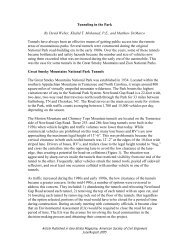
9.4.A. Geometric Design. (continued)d. Transition Sections. Tangent sections of roadways carry normal crown. Curved sections aresuperelevated. Transitions make a gradual change from one to the other. Superelevation runoff is thelength of roadway used to transition from full superelevation on a curve to a flat section on the outsidelane(s) on the adjoining tangent. Tangent runoff is the length of tangent required to transition from theabove flat section to full crown. In IHDS, the tangent runoff distance is user defined. Under normalconditions the distance should match the rate of superelevation. A detailed discussion of runoff begins onpage 175 in the Green Book.Where the alignment consists of tangents connected by circular curves, generally the superelevation beginson tangent, and full superelevation is attained some distance into the curve.Design practice is to place about two-thirds of the runoff on the tangent approach and one-third on thecurve. With a short tangent distance between reversing curves, the runoff length may require up toone-half of the length on the curve and one-half on the tangent.Give special attention to superelevation transition for broken-back curves. Figures 9-1 and 9-2 giveguidance in providing an adequate transition between curves in a broken-back situation.Figure 9-3 shows a method of checking templates for flat sections between reversing curves with a shorttangent.Many vehicles operate at speeds higher than the design speed on long tangents and flatter curves. Thesevehicles have to slow to the design speed in order to safely negotiate the sharpest curves. In areas of sharpcurves, the radius and the superelevation of adjacent curves should limit the difference in design speedbetween the curves to a maximum of 20 km/h. If the maximum differential is exceeded, the plans shallinclude advance curve and advisory speed signs for the lower speed curves.A method for determining superelevation rates for significant changes in curvature is detailed in theexample in Table 9-3.9 - 18
9.4. A. Geometric Design. (continued)60 90 120Tangent length (meters) between P.T. and P.C.Figure 9-2Superelevation Transitions for Broken-Back Curves9 - 20
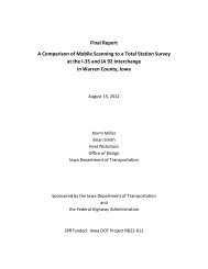
9.4.A. Geometric Design. (continued)Example: A 20 km/h maximum differential in design speed is allowed between adjacent curves andbetween a curve and a long tangent. For a maximum radius curve with a 50 km/h design speed, flattercurves on either side could be superelevated for a 60 km/h design speed. A curve at the end of a longtangent with an expected operating speed of 100 km/h would be superelevated for a 80 km/h design speed.Tangents over 120 meters in length are considered long tangents.Table 9-3 is an example of how to record design speeds for a project.The following is a list of the sample design data entered into the table.Given:Basic design speed = 60 km/h.e max = 8%Road alignment =190 m tangent, 600 m radius curve right,98 m tangent, 300 m radius curve left,84 m tangent, 200 m radius curve right,73 m tangent, 150 m radius curve left,80 m tangent, 300 m radius curve right,93 m tangent, 900 m radius curve left,97 m tangent.9 - 22
9.4.A. Geometric Design. (continued)Table 9-3Example Listing of a Determination of Superelevation RatesTangent / Curve Safe Speed Adjusted "e" for Adj. Run OffLeft/Right emax8% Design Speed Design Speed Length(meters)/(radius) (km/h) (km/h) (percent) (meters)190 m Tangent100 100600 m Radius 120 100 6.9 56Curve Right98 m Tangent300 m Radius 90 80 7.6 55Curve Left84 m Tangent200 m Radius 75 70 7.9 52Curve Right73 m Tangent150 m Radius 67 60 7.8 47Curve Left80 m Tangent300 m Radius 90 80 7.6 55Curve Right93 m Tangent900 m Radius 145 100 5.2 56Curve Left97 m TangentNOTE: Enter tangent length in meters and the curve radii in the first column. From Figure III-10 through Figure III-14,Design SuperelevationRates in the 1994 “Green Book”, determine the maximum safe speed at a superelevation rate of 8% for each curve and record in column 2. Nowadjust each curves design speed for the maximum 20 km/h differential between curves. Start with the sharpest curve (the 150 and 200 m radiuscurves) and continue by increasing the design speeds accordingly on the adjacent curves. Leaving a long tangent, the process is reversed. Startwith an estimated driving speed for the tangent and reduce the speed by 20 km/h for the adjacent curve. Record the runoff or spiral length actuallyused in the last column. These are helpful for future checking. Include the analysis in the design study.9 - 23
9.4.A. Geometric Design. (continued)If design speeds of horizontal curves are increased, the vertical curvature must meet the standards for theseincreased speeds. Where there is not enough runoff length between curves, redesign them to provide therunoff length or lower the design speed for one or both curves.5. Vertical Alignment. Vertical alignment consists of a series of gradients connected by vertical curves.Applicable design controls include safety, topography, functional classification, design speed, horizontalalignment, construction cost, cultural development, drainage, vehicular characteristics, and aesthetics. Theterms vertical alignment, profile grade and grade line are interchangeable.The topography of the land has an influence on alignment. AASHTO separates topography into threeclassifications of terrain:(1) Level or flat(2) Rolling(3) MountainousA description of these three types of terrain begins on page 226 in the Green Book.Terrain classifications pertain to the general character of a specific route corridor. For example, routes inmountain valleys and mountain passes that have all the characteristics of level or rolling terrain should beclassified as such. The terrain classification determines the maximum allowable grades in relation todesign speed.a. Vertical Alignment (Grade). Once the horizontal line is in the Interactive <strong>Highway</strong> Design System(IHDS), the designer should obtain a plot of the ground line and establish the vertical control points.Project the profile grade to fit these control points and the standards for percent of grade and vertical curvelength. To produce a desirable vertical alignment, the designer should use the following guidelines:Use a smooth grade line with gradual changes, consistent with the type of highway and character ofterrain. Avoid numerous breaks and short grade lengths.Avoid hidden dips. Hidden dips are hazardous on two-lane highways. They can hide approaching orslow moving vehicles or obstructions on the road ahead while deceiving the driver into believing that itis safe to pass or travel at high speed. Use long straight grades or introduce horizontal curves inconjunction with vertical curves to break up unsafe long tangents.Long steep grades affect traffic operation. If traffic volume is high, a slow moving vehicle lane orturnout requires study. On long downgrades, consider a truck escape ramp.On some steep grades, especially on low speed roads, it is desirable to break a sustained grade by making itsteeper at the bottom and flatter at the top. Short intervals of flatter grade permit high-powered vehicles toaccelerate and pass underpowered vehicles.On switch-back curves, flatten the grade to compensate for slower speeds.Avoid broken-back grade lines. Two vertical curves in the same direction separated by short tangents ispoor design practice particularly in sags where both curves are visible at the same time.Sag vertical curves at the ends of long tangents should be several times the length required for stoppingsight distance to avoid the appearance of an abrupt change in grade.9 - 24
9.4.A. Geometric Design. (continued)When at-grade intersections occur on roadways with moderate to steep grades, it is desirable to reducethe grade through the intersection.In swampy terrain and areas subject to overflow and irrigation, the low point of the subgrade should beat least 0.5 meters above the expected high water. For roads located along main streams and rivers, referto <strong>Chapter</strong> 7 for the appropriate hydraulic controls.b. Maximum Grade. The designer should know the functional classification of the project from theplanning and programming process (see <strong>Chapter</strong> 2). Consider this data, pages 227-241 of the Green Book,and the type of topography to determine the maximum allowable grades in relation to design speed.Example:- Rural Area.- <strong>Highway</strong> Functional Classification is Rural Collector.- 60 km/h Design Speed.- Rolling Terrain.According to the Green Book (Table VI-3, maximum grades, page 463), the maximum grade for thisexample is 8 percent.When analyzing maximum grades, note that superelevation transitions will increase the effective grade onthe edge of the traveled way. This increase is significant particularly to trucks and recreational vehicles.To minimize this effect on long continuous runs of near maximum grades, the designer has two options:(1) Flatten the grade throughout the curve.(2) Carry profile grade on the right edge of the traveled way going upgrade.This is especially important when the design contains climbing lanes or scenic pulloffs.c. Minimum Grade. Flat and level grades on uncurbed pavements are not objectionable when thepavement is adequately crowned to drain the surface laterally.A flat grade (0.00 percent) is acceptable in through-fill sections where the highway has sufficient crown.Minimum grades (0.5 percent) are applicable only for drainage of roadway ditches in cut sections, drainageof curb sections, and to ensure pavement drainage on superelevation transitions. This requirementparticularly applies where flat grades on crest and sag verticals have substantial lengths that are essentiallyflat. It also applies where superelevation transitions introduce sags in the ditch or gutter line. Computerplots of the ditch or gutter profiles will highlight any drainage problems for correction as the designprogresses.See Section 9.4.A.7, Geometric Cross Section, for details on design of drainage.9 - 25
9.4.A. Geometric Design. (continued)a. Stopping Sight Distance. A roadway design requires minimum stopping sight distance at all points,and where economically justified more liberal stopping distances are desirable.Minimum stopping distance is the least distance required to bring a vehicle to a stop under prevailingvehicle and climatic conditions. It depends on the initial speed of the vehicle, the perception and reactiontime of the driver, and the coefficient of friction between tires and roadway for the prevailing conditions.The coefficient of friction is much lower for wet pavements; therefore, wet rather than dry pavementconditions apply for establishing minimum values.Design controls for SSD are in the Green book, pages 117 to 125, 219, 223, and 283 to 293. Also seeTables 9-4 and 9-5 in this chapter.9 - 27
9.4.A. Geometric Design. (continued)b. Decision Sight Distance. Decision sight distance is the length of road a driver needs to receive andinterpret information, select an appropriate speed and path, and begin and complete an action in a safemaneuver. This distance is greater than the distance needed to simply bring a vehicle to a stop, andprovides for a reasonable continuity of traffic flow.If possible, provide decision sight distance in advance of any feature requiring increased driver awarenessand action. This includes intersections, lane changes, congested areas, pedestrian crossings, or otherfeatures. When decision sight distance is unavailable and relocation of the feature is not possible, thedesigner shall provide suitable traffic control devices.See design controls for DSD in the Green Book, pages 126 to 127. Also see Table 9-4 in this <strong>Chapter</strong>.c. Passing Sight Distance. Passing sight distance is generally applicable only to two lane, two-way roads.It is important for reasons of safety and service to provide as many passing opportunities as possible ineach section of road. The designer should try to ensure there are no long sections where passing is notpossible. The available passing sight distance has considerable influence on the average speed of traffic,particularly when a road is operating near capacity.The economic effects of reduced speed are indeterminate, but there is no doubt that road users benefitconsiderably when operating at or near design speeds with minimal traffic interference. The designershould consider these economic effects when setting horizontal and vertical alignments.Passing sight distance seldom applies on multilane roads. However, passing sight distance at the end oftruck-climbing and passing lanes where traffic must merge requires consideration.The designer should increase the sight distance in areas where vehicles operate above the design speed.Standard minimum passing distances for all classes of two-lane roads are given in the Green Book,pages 128 to 136.Design minimum passing sight distance requirements should not be confused with values provided in theMUTCD for determining no-passing zone pavement striping (MUTCD 3B-5).9 - 28
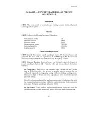
9.4.A. Geometric Design. (continued)Table 9-4Sight Distance Standards 1DesignSpeedkm/hAssumedSpeedkm/hSight Distance (meters)Stopping (SSD) Decision (DSD) Passing (PSD)Minimum Desirable Maneuver C Maneuver2MinimumE30 30-30 29.6 29.6 21740 40-40 44.4 44.4 28550 47-50 57.4 62.8 145 200 34560 55-60 74.3 84.6 175 235 40770 63-70 94.1 110.8 200 275 48280 70-80 112.8 139.4 230 315 54190 77-90 131.2 168.7 275 360 605100 85-100 157.0 205.0 315 405 670110 91-110 179.5 246.4 335 435 728120 98-120 202.9 285.6 375 470 792NOTE:1Based on passenger cars operating on wet pavement on grades 3%, the values for SSDshould be adjusted to the lengths shown in Table 9-5. Because truck and bus drivers are higher above thehighway surface than car drivers and can see the road further ahead, the values in the table are consideredadequate for trucks and buses.2The PSD values shown are minimum to allow one vehicle to pass and are based on a speed differential of15 km/h between the passing and passed vehicle. Longer lengths are desirable to allow more vehicles topass.9 - 29
9.4.A. Geometric Design. (continued)Table 9-5Effect of Grade on Stopping Sight DistanceDesignSpeed(km/h)Stopping SightStopping SightDistance (m) forAssumedDistance (m) forDowngrades:Speed forUpgrades:Condition3% 6% 9% (km/h) 3% 6% 9%30 30.4 31.2 32.2 30 29.0 28.5 28.040 45.7 47.5 49.5 40 43.2 42.1 41.250 65.5 68.6 72.6 47 55.5 53.8 52.460 88.9 94.2 100.8 55 71.3 68.7 66.670 117.5 125.8 136.3 63 89.7 85.9 82.880 148.8 160.5 175.5 70 107.1 102.2 98.190 180.6 195.4 214.4 77 124.2 118.8 113.4100 220.8 240.6 256.9 85 147.9 140.3 133.9110 267.0 292.9 327.1 91 168.4 159.1 151.3120 310.1 341.0 381.7 98 190.0 179.2 170.2d. Restrictions. Sight distance on horizontal curves is proportional to the radius of the curve. Manmadeobjects or naturally occurring conditions can restrict the line of sight across the inside of a curve.Typically, vegetation or a cut slope restricts sight distance.Provide adequate sight distance on horizontal curves by selecting the proper curve radius and arranging forthe removal or relocation of obstacles.Stopping sight distance (SSD) for the design speed of the highway must be provided on all horizontalcurves as a minimum. The SSD is measured from the eye height of a passenger car driver,1070 millimeters above the center of the inside lane, to an object 150 millimeters high on the center of theinside lane on the highway ahead. If the grade and superelevation are uniform throughout the SSD, thenthe midpoint on the line of sight is (1070+150)/2 = 610 millimeters above the center of the inside lane.This dimension determines the offset (M) on a cut slope at the midpoint of the SSD. See Figure 9-5.9 - 30
9.4.A. Geometric Design. (continued)The minimum lengths of vertical curves used in design are determined by the following formula:L = AKWhere:L = Minimum length of vertical curve in meters. (Round up to even tens, fifties, orhundreds.)A = Algebraic difference in grade in percent.K = Rate of change of grade (a constant value for a particular design speed and type of sightdistance). Obtain value from Table 9-6.NOTE: For small changes in grade (A) or for small values of (K), the computed lengths of vertical curvesmay be very short. For these conditions, use the minimum lengths specified in Table 9-6 instead of thecalculated length, provided it is longer. When practical, it is desirable to design vertical curves of150 meters or more in length, in order to create a pleasing appearance.9 - 35
9.4.A. Geometric Design. (continued)Table 9-6(K) Values for Determining Lengths of Vertical CurvesCrest Vertical CurvesSag Vertical CurvesBased On Based On Based On Based OnMinimumStopping Sight Decision Sight Passing Stopping SightDesignLengths ofDistance Distance Sight DistanceSpeed Crest orDistancekm/h Sag VerticalK K K K K K KCurves (m)Minimum Desirable Minimum Desirable Minimum Minimum Desirable30 3 3 50 4 4 1840 5 5 90 8 8 2450 9 10 52 99 130 11 12 3060 14 18 76 137 180 15 18 3670 22 31 99 187 250 20 25 4280 32 49 131 246 310 25 32 4890 43 71 187 321 390 30 40 56100 62 105 246 406 480 37 51 60110 80 151 277 468 570 43 62 66120 102 202 348 547 670 50 73 72Note: The minimum PSD shown in Table 9-6 is significantly less than shown in Table 9-4. ThePSD in Table 9-4 assumes the passed vehicle is operating at or near the design speed. Thedistances in Table 9-6 allow opportunities to pass slower moving vehicles.9 - 37
9.4.A. Geometric Design. (continued)7. Geometric Cross Section. The highway cross section is defined as the finished or the proposedfinished section between construction limits. (See Figure 9-9.)Roadway section configurations depend on functional classification criteria. The criteria show thecross-section characteristics of the roadway section based on the Green Book, State developed andapproved classifications, NPS standards, or other applicable agency standards.Most <strong>Federal</strong> roads have an asphalt concrete surface. Some highways are graded under several contractsand the ultimate pavement is placed when a long section of the route is ready. Under the grading contracts,the base courses may be placed and then surfaced with an interim asphalt surface treatment. Occasionally,a roadway with gravel surfacing is requested by the client agency.a. Pavement Structure. The pavement structure refers to the material and depth of base and pavementplaced on the finished subgrade. The pavement structure design should use the minimum depth of materialnecessary to carry the projected loads over the design life of the pavement. The design shall also providefor a smooth-riding, skid-resistant surface.A normal pavement structure design has a 10 to 20-year life. The geotechnical staff bases the design onsoil samples and the predicted volume and type of traffic using the highway during the design life. Thepavement structure thickness varies with climatic conditions and the type and strength of subgrade materialused (usually in the top 300 to 600 millimeters of subgrade).9 - 38
9.4.A. Geometric Design. (continued)At the beginning of a design, the depth of the pavement structure may be arrived at by an assumptionbased on experience or by comparing with the depths used on an adjacent project. Following ageotechnical investigation, the designer will adjust the assumed depth accordingly. The geotechnicalinvestigation usually takes place after a line and grade have been established.For RRR projects, the riding quality of an asphalt surface may be improved by providing a leveling course.This additional depth may increase the pavement structure capabilities and merits consideration in the finalpavement design when leveling is relatively uniform over the length of the project. If a field review of theproject is not practical, the designer should increase asphalt concrete pavement quantities by 20 percent foruse as leveling material. See <strong>Chapter</strong> 6 for additional details on the design of asphalt and concretepavements.b. Profile Grade Location and Cross Slope. The standard location of profile grade on the highway crosssection is at centerline or low side of the superelevated section for all two-lane highways.The cross slope on tangents on paved highways shall be from 1.5 to 2.0 percent.Normally, the cross slopes on gravel surfaced roads shall be 3 to 4 percent.The shoulder cross slope should be the same as the adjacent traffic lane. With curb sections or when theshoulder surface is an asphalt surface treatment, aggregate, or turf, increasing the slope helps to facilitatedrainage. In these cases, consider cross slopes of 4 to 6 percent. On super elevated curves, the roll-over incross slope on the outside of the curve should not exceed 8 percent.The cross slope on the tops of base courses and the subgrade is usually the same as on the finishedpavement. In some cases it is desirable to have a reverse slope on the subgrade (on the high side of curvesand outside the edge of the pavement) to prevent moisture from entering the base.c. Lane and Shoulder Widths. The Green Book and other agency standards show lane and shoulderwidths for each functional classification for various design speeds and traffic volume ranges.When the percentage of trucks or recreational vehicles is high in comparison to the ADT, considerincreasing lane widths.d. Foreslopes. Foreslopes ensure the stability of the roadway and provide a reasonable opportunity forrecovery of an out-of-control vehicle. The foreslope, the slope from the edge of the surfaced shoulder tothe edge of the subgrade shoulder, should not be steeper than the slope ratios shown in Table 9-7, unlessguardrail is placed (Detail designs should be in accordance with the Roadside Design Guide, AASHTO,1996).The slope from the edge of the subgrade shoulder to the bottom of the ditch should normally be anextension of the foreslope.9 - 40
9.4.A. Geometric Design. (continued)Table 9-7Foreslope RatiosGuidelines for Foreslopes Including Ditch SectionsDesign VolumeDesign Speed (km/h)(ADT) 30 40 50 60 70 80 90 100 110Less than 250 1:3* 1:3* 1:3* 1:3* 1:3* 1:3* 1:4 1:4 1:5250 to 500 1:3* 1:3* 1:3* 1:3* 1:4 1:4 1:4 1:4 1:5501 to 1000 1:3* 1:3* 1:3* 1:3* 1:4 1:4 1:5 1:5 1:51001 to 3000 1:3* 1:3* 1:3* 1:4 1:4 1:4 1:5 1:5 1:6Greater than 3000 1:4 1:4 1:4 1:4 1:5 1:5 1:6 1:6 1:6*Slopes steeper than 1:4 are traversable but are not considered recoverable and should be avoided.On RRR projects, the proposed work on the roadway may affect the foreslopes from the edge of pavementto the hinge point of the fill slope and ditch foreslopes.The following points should also be noted:When the existing roadway geometrics are retained and the foreslopes are steeper than 1:4, reshapingto provide a flatter foreslope is desirable.There are cases where the roadbed width will not accommodate foreslopes of 1:3 or flatter. There alsomay be restrictions on filling of ditches to provide width or widening of embankments. When thisoccurs, consider strengthening the existing pavement structure through a recycling-in-place processrather than overlaying the project. A narrower pavement width to maintain a 1:3 foreslope and preventan undesirable edge drop-off is also a reasonable solution.It is desirable to flatten crossroad/road approach foreslopes to 1:10. Provide at least a 1:4 minimumslope. Move the crossroad/road approach drainage away from the mainline to maintain the integrity ofthe clear zone and reduce the length of pipe required.e. Roadway Ditches. The ditch cross section must be adequate to accommodate drainage of thepavement and cutslope. <strong>Chapter</strong> 7 covers the details of hydraulic design.Ditches should have a streamlined cross section for safety (<strong>Chapter</strong> 8) and ease of maintenance. Wideditch bottoms are used in rock fallout areas as well as in projects designed with side borrow.Generally, roadway ditches have a "v" shape formed by the foreslope from the subgrade shoulder and cutslope. The depth of the ditch is dependent on hydraulic needs. It should normally be from 150 to 300millimeters below subgrade for safety and maintenance purposes. When hydraulic needs dictate ditches ofgreater capacity, a flat bottom ditch takes precedence over deepening the v-ditch.The designer should obtain computer plots of the roadway ditch profiles to check for sags in the ditch line.These profiles will show where the installation of culverts or the construction of special ditch grades willeliminate ponding.9 - 41
9.4.A. Geometric Design. (continued)and will enhance aesthetics, safety, and maintenance. Slopes 1:3 are generally traversable by a vehicle thathas run off the road but do not provide for vehicle recovery. Slopes 1:3 and flatter are also traversable byself-propelled mowers, and should be used at locations where the grass will be regularly cut. High cutsand fills normally have steeper slopes.Cuts have a high visual impact, therefore, the design of cut slopes requires careful consideration. In somecases, it is desirable to use the same slope throughout the cut, while in other situations a constant distanceto the catch point stake and a continuously varying slope may be appropriate.In steep terrain, the slopes may be varied slightly from standard slopes in order to better fit the topographyor eliminate high "sliver" cuts or fills. Transition slopes between common material and rock requirespecial consideration. Blend the ends of cut slopes into the natural terrain by rounding, flattening, orotherwise shaping the ground line.Transition fill slopes from the main portion of the fill into the cut section. Transitions between flat andsteep slopes should be sufficiently long to provide a pleasing appearance. A transition from a 1:4 slope toa 1:1.5 slope may require a distance of 50 meters or more to appear natural.Table 9-8 lists commonly used slopes for cuts and fills in earth materials. Use this table as a guide, alongwith the recommended slopes in the geotechnical report, to design the slopes on the project. All fill slopessteeper than 1:4 should be evaluated for safety. (See <strong>Chapter</strong> 8.)Geotechnical reports may not be available for the project when beginning a design. If this is the case,design cut and fill slopes based on available survey or field review data. When a geotechnical reportbecomes available, the designer must review the slopes initially used and make any necessary adjustmentsin the earthwork design.9 - 43
9.4.A. Geometric Design. (continued)Table 9-8Desirable and Maximum SlopesCut and Fill Slope Ratios for Soil MaterialsHeight Slope Flat Rolling Mountainous(meters) Type Desirable Maximum Desirable Maximum Desirable Maximum0-1 Cut 1:6 1:4 1:6 1:4 1:6 1:3Fill 1:6 1:4 1:6 1:4 1:6 1:41-3 Cut 1:4 1:3 1:3 1:2 1:3 1:2Fill 1:4 1:4 1:4 1:4 1:3 1:33-4.5 Cut 1:3 1:2 1:3 1:2 1:3 1:2Fill 1:4 1:3 1:4 1:3 1:3 1:1.54.5-6 Cut 1:3 1:2 1:2 1:2 1:2 1:1.5Fill 1:3 1:2 1:3 1:2 1:2 1:1.5Over 6 Cut 1:2 1:1.5 1:2 1:1.5 1:2 1:1.5Fill 1:3 1:2 1:3 1:1.5 1:2 1:1.5NOTE:Cut and fill slopes steeper than 1:2 should be avoided in clay or silty soils subject toerosion. Fill slopes steeper than 1:1.5 may be used in critically tight areas with geotechnicalguidance when the fill material is composed of quality rock.g. Rock Cut Slopes. Generally, rock slopes vary from near vertical to 2:1, depending on the type andquality of rock, joint patterns, fractures, cross bedding, etc. Rock slopes dipping toward the roadway mayrequire flatter slopes.High cuts, particularly in weathered or weak rock, may require fallout ditches for stability and safety. Afallout ditch at the bottom of high rock cuts keeps falling rock from encroaching on the highway. Ageotechnical investigation will determine the need for fallout ditches, their width, and necessaryconfiguration.When soil or highly weathered rock overlays the solid rock, overburden benches at the top of the solid rockmay be desirable. The overburden slope should range from 1.33:1 to 1:2, depending on the type and depthof overburden and the steepness of the topography. When the rock surface is known, compound slopeswork very well.From a safety viewpoint, rock cuts should be vertical or nearly vertical if the rock will stand on theseslopes. Under these conditions, falling rocks seldom roll once they hit the ditch. Rock cuts on the insideof curves designed on 5:1 or flatter slopes prevent the appearance of an overhang to drivers.Figures 9-11 and 9-12 provide guidance for designing rock cuts and fallout ditches. However, the finaldesign shall rely on the recommendations in the geotechnical report. Typical sections for rock cuts shouldbe shown on the plans.9 - 44
9.4.A. Geometric Design. (continued)The normal rockfall protection is provided by the typical V-ditch with the minimum width shown in Figure9-11. Rock slopes higher than 10 meters from shoulder grade may require wider fallout ditches and thegeotechnical staff should be consulted. Cuts less than 6 meters in height generally do not require a falloutditch.The added rock protection features shown in Figures 9-11 and 9-12 may be applicable on higher volumehighways experiencing falling rock. The geotechnical unit should recommend or approve these featuresbefore inclusion in a project.9 - 45
9.4.A. Geometric Design. (continued)h. Serrated Slopes. Serrated slopes are a series of small steps in soft rippable rock cuts having sloperatios between 1.3:1 and 1:2. The steps allow weathering and decomposing rock to accumulate to providea growing medium for plants. The flat steps also retain moisture for use by the growing plants. Whenusing serrated slopes, take into consideration local environmental conditions, soil, and plant growthpotential. Figure 9-13 shows a typical section of a serrated slope.Include a drawing in the plans showing step tread and rise dimensions. Generally, the step rise varies from0.5 meters for easily ripped rock to 1.5 meters for harder rippable rock. The step tread width is equal tothe rise multiplied by the cut slope ratio.9 - 48
9.4.A. Geometric Design. (continued)I. Slope Rounding and Clearing Limits. Rounding at the top of cut slopes is especially important toreduce erosion and ensure long term stability and revegetation of cut slopes. It also adds to the aestheticsof the finished project by blending the slope into the natural terrain. The amount of rounding may dependon the environmental impact and on the desires of the agency having jurisdiction.It is <strong>FLH</strong>O policy to encourage the use of slope rounding on all projects.For low fills, it is desirable to have a clearing width beyond the edge of the travel lane that provides a clearzone for vehicles that may run off the road. This applies to daylighted sections and low cuts except inguardrail locations. Refer to <strong>Chapter</strong> 8 for information on determining clear zone widths.In some cases the horizontal sight distance near intersections and on the insides of horizontal curvesrequires wider clearing than normal. Figures 9-5 and 9-6 will aid in determining widening needed toprovide adequate site distance. When wider clearing is necessary, it shall show on the plans.There are special cases where it is desirable to widen the clearing to create openings and irregularities in along straight clearing line. The treatment will depend on the type, size, and density of the trees and groundcover and on the terrain. Each case merits consideration on an individual basis.8. Miscellaneous Roadway Widening. Roadways often require special consideration for additionalwidening for curves, auxiliary lanes, turnouts, etc.a. Curve Widening. The rear wheels of longer vehicles do not follow or track the front wheels onhorizontal curves. To accommodate this, it is good practice to increase traveled way widths on curves,particularly when lane widths are less than 3.6 meters.Traveled way widening values are shown in Table III-22 on page 217 in the Green Book. Place thewidening on the inside of curves and transition it throughout the length of the superelevation runoff. Thefinal centerline striping should split the pavement to provide equal widening to both lanes.b. Auxiliary Lanes. Auxiliary lanes adjoin the traveled way and provide for parking, speed change,turning, weaving, truck climbing, passing, or other purposes supplementary to through-traffic movement.They also maintain lane balance and accommodate entering and exiting traffic.(1) Parking Lanes. The design of arterial or expressway facilities should only permit emergency stoppingor parking. Within most urban areas existing and developing land uses require on-street parking. Thismay also be true of small rural communities located on arterial highway routes.When land use development requires parking lanes, consider only parallel parking. Do not use diagonal orangle parking without a careful analysis of operational characteristics of the facility.The width of parking lanes can vary from 2.1 to 3.6 meters depending on the use of the lane for purposesother than parking automobiles. Refer to the Green Book, pages 411-413, 474, 521, and 539 for criteria ondesign of parking lanes.(2) Speed Change Lanes. Vehicles use acceleration and deceleration lanes, including tapered areas, whenentering or leaving the through traffic lanes. There are no definite warrants for providing speed changelanes. The Green Book provides guidance on the use of these lanes on pages 749-751, 781-782, 952-957.Figures 9-14 and 9-15 in this chapter provide distances for deceleration and acceleration lengths requiredfor automobiles.9 - 50
9.4.A. Geometric Design. (continued)subsurface. Their purpose is to extend the service life, provide additional pavement strength, restore orimprove the original cross section, improve the ride of the roadway, and enhance safety. An RRR projectshould not decrease the existing geometrics of the roadway section. See TRB Special Report 214, DesigningSafer Roads for additional information.Funding restrictions may prevent improvement of existing highways to the desirable standards. Therefore,when the pavement condition reaches minimal service level, there is a need for cost effective pavement andimprovement projects.RRR projects reflect and emphasize the economic management of the highway system. Therefore, economicconsiderations will largely determine the scope of work.Many factors influence the scope of a RRR project, such as the following:Roadside conditionsFunding constraintsEnvironmental concernsChanging traffic and land use patternsPavement conditionAccident dataAcquisition of additional right-of-way to construct RRR improvements is sometimes necessary. Horizontaland vertical alignment modifications, if any, should be minor.The Designer should review the project in the field and include those items that will be practical enhancementsto the project. These items may include the following:Roadside obstacle removalDrainage improvementsSlope rounding or flatteningTraffic barrierTraffic control devicesShoulder improvementsMinor wideningBridge railsIntersection improvementsRailroad-crossing improvementsIlluminationMany of these work items will enhance the project by providing the broadest scope of improvementpossibilities.Carefully establish project limits, particularly where widening occurs. Avoid ending the project at potentiallyhazardous locations, such as a narrow structure or a severe vertical or horizontal curvature. Provide theappropriate safety measures when these conditions are unavoidable.All safety elements of an RRR project merit specific consideration. Collect and analyze accident numbers,types, and rates for the project to identify safety problem areas. In addition, field reviews can identifypotentially hazardous conditions.9 - 55
9.4.A. Geometric Design. (continued)While an analysis may indicate deficiencies in one or more of the following areas, each needs examination:Horizontal and vertical alignmentCross-sectional geometricsTraffic controlAccessRailroad crossingsPedestrian/bicycle facilitiesBridgesIlluminationSigningChannelizationSkid-resistant surface textureImprovements to the roadway surface may result in increased operating speeds. To maintain an acceptablelevel of operational safety, examine the geometrics and modify them if necessary.Horizontal and vertical curvature and stopping sight distance directly relate to the speed of vehicles. As aconsequence, major deviations from the standards may cause speed related problems.When curvature is the cause of accidents, consider some corrective action. This can range from positiveguidance (such as placement of additional warning signs and markings) to reconstruction. Often, existinghorizontal and vertical alignments are adequate, and an analysis will show they only require signing andmarking.Consider alignment improvements when accident experience is high and previously installed warning signs,markings, or other devices have been ineffective.When the design speed for a horizontal or vertical curve is less than 20 km/h below the design speed of theadjacent sections, and has a low accident history, signs and marking may be applicable instead ofreconstruction. When the difference is 20 km/h or more or the design speed of the horizontal or vertical curveis less than 30 km/h, corrective action is essential. If improvement is not possible, provide the appropriatesigns and markings and other provisions to obtain proper speed transition.Sight distance improvement on horizontal curves and at intersections consists of flattening cut slopes, selectiveclearing, or both. On completion of this work, measure the actual sight distance, determine the maximumcomfortable speed, and sign and mark the location.As a rule, grades cannot be flattened on RRR projects. However, steep grades and restricted horizontal orvertical curvature in combination may warrant corrective action.It is desirable to provide a roadside recovery area as wide as practical using the guidelines in <strong>Chapter</strong> 8. Makean evaluation to determine the consistency of the clear zone throughout the project limits. Following this,determine the severity of each situation. Give particular attention to the clear zone at identified high roadsideaccident locations (fixed object accidents). Perform a cost analysis of appropriate measures (e.g., do nothing,remove, protect) to mitigate the hazardous conditions. On the basis of these analyses, select the appropriateremedial action. An adequate clear zone on horizontal curves at the end of a downgrade merits specialattention.9 - 56
9.4.A. Geometric Design. (continued)Consider widening to provide additional clear distance through short sections of rock cuts. In longer rock cuts,protrusions are cut back or protected where warranted. A review of accident data will help to define dangerousobstructions. Good engineering judgment, cost effectiveness, and consideration of environmental andcommunity impacts may also influence decisions.Under urban conditions, the minimum setback for obstructions should be outside the paved shoulder or600 millimeters behind the curb. Where there will be sidewalks, it is desirable to locate the obstructionsbehind the sidewalk.Safety items reduce the severity of run-off-the-road accidents. These items include traffic barriers (includingbridge rails), flattening slopes to eliminate the need for barriers, crash cushions, breakaway or yielding signsupports, and breakaway luminaire supports.Refer to section 10.3.F in <strong>Chapter</strong> 10 for a discussion on bridges on RRR projects.All RRR projects should consider the following safety enhancements:Upgrading all rail and end treatments to current standards. Evaluate existing traffic barrier rail, bridge rail,guardrail, and end treatments for need and compliance with standards.Extending cross pipes outside of the clear zone if practical, orInstalling beveled pipe ends or end sections for both parallel and cross-drain structures located in the clearzone.Relocating, protecting, or providing breakaway features for sign supports and luminaries.Protecting exposed bridge piers and abutments.Modifying raised drop inlets that present a hazard in the clear zone.Sign and mark all RRR projects according to the MUTCD.9 - 57
9.4.B. Intersection Design.B. Intersection Design. This section sets the basic guidelines to use in the design of at-grade intersections.The designer should also be familiar with "At-Grade Intersections", <strong>Chapter</strong> IX of the Green Book. Forinformation on intersections with grade separation and interchanges, see <strong>Chapter</strong> X of the Green Book.Intersections at grade are a critical part of highway design. The efficiency of a road network depends on theeffectiveness of the intersections. The number of possible conflicts at intersections is very high compared tonormal roadway operations. Good design practice will minimize these areas of high accident potential.Traffic, driver characteristics, physical features, and economics influence the design of channelization andtraffic control measures.It would be ideal to design every intersection based on an engineering analysis using traffic data and accidentrecords, but this is seldom practical. When an engineering study is appropriate, it should includerecommendations for channelization, turn lanes, acceleration and deceleration lanes, intersection configuration,and traffic control devices.The speed at which vehicles approach and move through the intersection and the size of the design vehiclegovern the minimum dimensions of an effective intersection. Such features as minimum sight distance, curveradii, and lengths of turning and storage lanes directly relate to speed and design vehicle. (See paragraph9.4.B.2.)1. Intersection Types. The three-leg, four-leg, and multileg configurations are the three basic types ofintersections. (See Exhibit 9.3.)The three-leg configuration is generally referred to as either a tee or wye intersection. The teeintersection has three legs intersecting so the angle between the stem of the tee and the remaininglegs is 60° to 120°. It is desirable to keep this range between 75° and 105° with 90° being the ideal.The tee shape provides better driver visibility than the wye shape. It is preferable to have the minortraffic movement on the stem of the tee.In the wye intersection, the angle between two of the intersecting legs is less than 60°. The wyeshape can cause driver confusion when two legs diverge from the stem and thus requires carefulsigning.The four-leg intersection is the most common type of intersection and may be right angled, oblique,or offset. The desirable angle between any two respective legs is between 75° and 105° although theGreen Book will allow a range from 60° to 120° with 90° preferred.The right-angled crossing is easily signed and signalized, provides good visibility, and is the safestto negotiate by drivers and pedestrians. The oblique crossing creates problems with driver visibility,pedestrian safety, and vehicle turning angles. The offset intersection has low intersection capacity,is difficult to negotiate and comprehend, and is difficult to effectively sign and signalize. Thethrough traffic movement on the major roadway should have the straight alignment.9 - 58
9.4.B. Intersection Design. (continued)The multileg intersection has more than four intersecting approach legs and can form severalconfigurations. For purposes of this discussion, the rotary intersection is considered to be a multileg.These intersections have visibility problems and poor turning angles, confuse the road user, and aredifficult to sign, mark, and signalize. This type of intersection occurs when a highway diagonallycuts across a street grid system or when more than four approach legs intersect. The multilegconfiguration is not appropriate for new highways, and the reconstruction of existing multilegs to thefour-leg type intersection is very desirable.The “roundabout” intersection, a small radius version of a rotary intersection/traffic circle hasworked well on some low-speed routes as replacements for intersections with 4-way stops. It hasbeen very successful in reducing accidents, but failures have shown that site selection is critical tosuccessful performance.2. Design Vehicle. Design vehicles have selected dimensions and operating characteristics. Each representsa class of vehicles that establish design controls for specific conditions.The design vehicle for any intersection depends on the roadways involved, the location of the intersection, andthe types and volume of vehicles using the intersection. Table 9-9 provides a guide to determine the designvehicle appropriate for various intersections.Design an intersection so the design vehicle can make all turning movements without encroaching on adjacentlanes, opposing lanes, curbs, or shoulders. Using a taper at the exit end of the right-turn corner will reducethe radius and the pavement area. For the recommended right-turn corner design see Section 9.4.B.8, Right-Turn Lanes.Table 9-9Intersection Design VehicleDesign VehiclesRadius (meters)Intersection Type Desirable Minimum Desirable MinimumJunction of Major Truck Routes WB-19 WB-19 35 30Junction of State Routes WB-15 WB-12 30 23Ramp terminals WB-15 WB-12 30 23Other Rural WB-12 SU 23 17Urban Industrial WB-12 SU 23 17Urban Commercial SU P 17 11Residential SU P 17 11Note:P = Passenger car, including light delivery trucks.SU = Single unit truck.WB - 12 = Semitrailer truck, overall wheelbase of 12 meters.WB - 15 = Semitrailer truck, overall wheelbase of 15 meters.WB - 19 = Semitrailer truck, overall wheelbase of 19 meters.9 - 59
9.4.B. Intersection Design. (continued)3. Alignment. When the gradient of an intersecting roadway exceeds the cross slope of the through pavement,it is desirable to adjust the vertical alignment using suitable grades and vertical curves. Any adjustment shouldmaintain sight distance.To determine the maximum grade of a minor road at an intersection refer to Exhibit 9.4. In areas of ice orsnow conditions it is desirable to use a 3 percent maximum grade, but the grade should not exceed 5 percent.A minimum grade of 0.5 percent will provide for adequate drainage at an intersection.When the desirable criteria is not attainable for an intersection, suitable curves introduced into the horizontalalignment of the less important road will reduce the angle of the intersection. Exhibit 9.5 shows someexamples of intersection horizontal realignments.Often the cross slope of a road is in the same direction as the intersecting cross road. In this case adjust thevertical alignment of the cross road to meet the pavement cross slope of the highway.If possible, avoid or eliminate intersections where the cross slope of the curving road is not in the samedirection as the grade of the intersecting cross road. If this is unavoidable, adjust the vertical alignment of thecross road far enough from the intersection to obtain a desirable alignment. (See Exhibit 9.4.)4. Sight Distance. The operator of a vehicle approaching an at-grade intersection needs an unobstructed viewof the entire intersection and a sufficient length of the intersecting roadway. Under some conditions, whenit is impractical to provide adequate site distance for cross road traffic to safely enter the main road, it may benecessary to install traffic signals. (See Part IV of the MUTCD.)Many intersections use stop signs on the minor road for traffic control. In this case, the driver stopped on theminor road must see enough of the major highway to safely cross before a vehicle on the major highway canreach the intersection.See Exhibit 9.6 for minimum sight distance along the major road for level conditions. In Exhibit 9.6, the timefor acceleration value (t a) multiplied by the applicable adjustment factor from Table 9-10 will adjust theminimum sight distance to reflect grades of the minor road approach.Table 9-10Sight Distance Adjustment FactorDesign Cross Road Grade (percent)Vehicle - 4 - 2 0 + 2 + 4P 0.7 0.9 1.0 1.1 1.3SU 0.8 0.9 1.0 1.1 1.3WB- 15 0.8 0.9 1.0 1.2 1.7Within the sight triangle, remove, adjust or lower cut slopes, hedges, trees, signs, utility poles, or anythinglarge enough to constitute a sight obstruction (see the Green Book, pages 696-721). Eliminate parking andoffset signs to prevent sight distance obstructions.9 - 60
9.4.B. Intersection Design. (continued)The SU vehicle serves as the design vehicle for most rural highway conditions, including most recreationalroads. If there is significant semi-truck traffic, use the WB-15 or WB-19 vehicles. In areas where SU or WBvehicles are not prevalent, and ROW restrictions prohibit adequate sight triangle clearing, the P design vehiclemay be applicable.At some intersections the turning volume from a stop-controlled minor roadway is significant enough toconflict with through vehicles on the major roadway. In these instances, sight distances shown in Table 9-11are recommended. The distances shown in the table for P or SU design vehicles are the sight distancesrequired for P vehicles to turn onto a two-lane highway and attain an average running speed without beingovertaken by a vehicle going the same direction. The distances shown in the table for the WB-15 and WB-19design vehicles are the sight distances required for them to complete a left turn. Using sight distances less thanthat required for the P or SU vehicle will require the through traffic to reduce speed.For additional information on sight distance and for sight distance across divided highways, refer to <strong>Chapter</strong> IXof the Green Book.Table 9-11Sight Distance for Turning VehiclesDesign SpeedDesign Vehicle(km/h) P or SU WB - 15 WB - 1930 110 130 15040 120 155 18050 145 195 22560 160 235 27070 235 270 31580 315 315 36590 395 395 405100 475 475 475110 565 565 5655. Channelization. Channelization separates traffic into definite paths of travel using pavement markings orraised islands. Channelization facilitates the safe and orderly movement of vehicles, bicycles, and pedestrians.Pavement markings used to delineate travel paths generally consist of painted stripes reflectorized with glassbeads. Raised Pavement Markers (RPM), reflectorized and nonreflectorized, may supplement pavementstriping when increased visibility is desirable. RPM may replace painted stripes when climatic or trafficconditions warrant. (See <strong>Chapter</strong> 8).Curbing is permissible for channelization under the following conditions:Prevention of mid-block left turns.Raised divisional and directional islands.Raised islands with luminaries, signals, or other traffic control devices.Pedestrian refuge islands.<strong>Lands</strong>caped areas within the roadway.Curbing is undesirable at any location where painted pavement markings with or without reflective lanemarkers attain the same objective.9 - 61
9.4.B. Intersection Design. (continued)Try to limit the use of curbing to urban and suburban highways with a design speed of 60 km/h or less. Onthese types of highways, drivers expect to encounter confined facilities and raised channelization works well.The two general classifications of curbing for channelization are mountable curbs and barrier curbs of the typesshown in Figure IV-4 on page 346 of the Green Book. For safety considerations, use mountable curbingwhenever possible. Use barrier curb for raised islands with luminaries or traffic control devices and forpedestrian refuge.Table 9-12 shows the minimum offset distances recommended for barrier curb. For mountable curbinginstallations, the left offset distance is optional.Table 9-12Offset Distances for Barrier CurbLane Left RightWidth Rural Urban Rural and Urban(m) (m) (m) (m)3.6 0.3 0.3 1 minimum3.3 0.6 0.3 1 minimum3.0 1.0 0.6 1 minimum6. Traffic Islands. A traffic island is a defined area between traffic lanes for control of vehicle movements,pedestrian refuge or traffic control devices. The use of raised traffic islands should be limited to those urbanand suburban highways with a design speed of 60 km/h or less.Traffic islands perform these major functions:Channelization islands control and direct traffic movement.<strong>Division</strong>al islands separate opposing or same direction traffic streams.Refuge islands provide safe haven for pedestrians.Miscellaneous islands provide for proper placement of traffic control devices.<strong>Division</strong>al and refuge islands are normally elongated and should be at least 1.2 meters wide and 6 meters long.Channelization islands are normally triangular. In rural areas they should contain an area of at least 7 squaremeters with 9 square meters as a desirable minimum. In urban areas where speeds are low, islands abouttwo-thirds this size may be acceptable. Islands with traffic control devices or luminaries and islands crossedby pedestrians require 18 square meters as a minimum area.Design triangular shaped islands as shown in Exhibit 9.7. The offset distances illustrated apply to islandsconstructed with mountable curbs. For painted islands in rural areas, these offset distances are desirable butnot mandatory. With barrier curbing provide the minimum offset distances shown in Table 9-12 but not lessthan those shown in Exhibit 9.7. Increase the offsets of the approach noses of the islands when the minimumoffset distance shown in Exhibit 9.7 is increased.9 - 62
9.4.B. Intersection Design. (continued)Avoid offset distances wider than 1.5 meters as this gives the appearance of an added lane. Reflective RPMsmay supplement island markings.Raised islands at crosswalk locations require barrier-free access for the handicapped. (See Section 9.4.F.6.)Design approach ends of islands to provide adequate visibility and advance warning of their presence. Islandsshould not cause a sudden change in vehicle direction or speed. Transverse lane shifts should begin far enoughin advance of the intersection to allow gradual transitions. Avoid introducing islands on a horizontal or verticalcurve. When islands on curves are unavoidable, adequate sight distance, illumination, and/or the extensionof the island must be considered.See Part V of the MUTCD and the Green Book for additional design criteria for islands.7. Left-Turn Lanes. A left-turn lane is an auxiliary lane on the left side of a one-directional pavement for useas speed change and storage of left-turning vehicles. Left-turn movements result in more critical trafficconflicts than do right-turn movements. Design left-turn channelization with enough operational flexibilityto function under peak loads and adverse conditions. Left-turn lanes are an economical way to reduce delaysand accidents at intersections.At unsignalized intersections on two-lane highways, use Figure 9-17 for guidance on the need for left-turnlanes. Left-turn lanes are appropriate at locations where accidents involving left- turning vehicles are high.Refer to Figures 9-18 through 9-20 and Table 9-13 to determine the storage length required. The minimumstorage length should be 30 meters. At signalized intersections the left-turn storage length is dependent oncapacity and level of service criteria found in the <strong>Highway</strong> Capacity Manual.Exhibit 9.8 shows typical left-turn geometrics to accommodate a left-turn lane. Offsets and pavementwidening should be symmetrical about centerline or baseline. Widen on one side only when right-of-way,topography, alignment restrictions, or other circumstances prevent symmetrical widening. See the Green Bookfor additional design guides and for left-turn treatments on multilane facilities.8. Right-Turn Lanes. Right-turn corner designs should allow the design vehicle to turn without encroachingon adjacent lanes, curbs, shoulder edges, or opposing traffic lanes. Exhibit 9.9 shows typical design for thedesign vehicles using a taper at the exit end of the right-turn corner. For a simple radius without the exit taper,the values in Table 9-9 apply, however, this will increase the pavement area. At signalized intersections someencroachment on adjacent lanes of the approach leg is usually acceptable to obtain an adequate radius.Where larger radii than those given in Table 9-9 or Exhibit 9.9 are desirable, compound curves may reducethe need for additional pavement area. See the Green Book for a discussion of compound curves and otherguidelines for corner radius returns.9 - 63
9.4.B. Intersection Design. (continued)Right-turn movements at intersections influence intersection capacity, although not usually to the same extentas left-turning movements. Conflict between the opposing traffic and the right-turning vehicle is not a factor.Right-turning vehicles are affected by pedestrian movements, especially those in the crosswalk of the leg intowhich the turn is being made.Consider right-turn lanes at unsignalized intersections when:Approach and right-turn traffic volumes are high. See Figure 9-21.Presence of pedestrians requires right-turning vehicles to stop in the through lanes.Restrictive geometrics require right-turning vehicles to slow considerably below the speed of thethrough traffic.The decision sight distance is below minimum at the approach to the intersection.Accidents involving right-turning vehicles are high.At signalized intersections, a capacity analysis using the <strong>Highway</strong> Capacity Manual will determine if right-turnlanes are necessary to maintain the desired level of service.Where adequate right-of-way exists, providing right-turn lanes is cost effective and can provide increasedsafety and operational efficiency.Table 9-13Additional Left-Turn Storage for Trucks atUnsignalized Two Lane <strong>Highway</strong> IntersectionsStandardTrucks in Left-Turn MovementStorageLength 10% 20% 30% 40% 50%Additional storage length to be added to standard values of left turn lengths.(meters)304560(meters) (meters) (meters) (meters) (meters)7.5 7.5 15 15 157.5 15 15 22.5 22.57.5 15 22.5 30 309 - 64
9.4.C. Earthwork Design.C. Earthwork Design. Earthwork design includes the following:- Clearing and grubbing.- Additional clearing and grubbing.- Removal of structures and obstructions.- Excavation and embankment.- Rock blasting.- Watering.- Earthwork geotextiles.- Structure excavation and backfill for selected major structures.- Structure excavation and backfill.- Drainage layer.- Roadway obliteration.- Linear grading.- Subgrade stabilization.1. Clearing and Grubbing. Clearing widths should extend 1.5 meters beyond the outer limit of sloperounding for cuts and 1.5 meters beyond the toe of fill. Additional clearing and grubbing includes thefollowing:Additional clearing or selective thinning of vegetation at the top of high cuts.Additional clearing for scalloping and vistas to improve visual appearance.Additional clearing required for the accommodation of utilities.Additional clearing to allow for southern exposure to assist in melting snow in high elevations.Clearing and grubbing widths may be limited under the following situations:Decreased clearing allowance in sensitive areas, such as National Parks or areas where the preservationof existing vegetation is critical.Decreased clearing because of limited Right-of-Way (R/W).Clearing and grubbing quantities are normally computed using IHDS except for isolated areas of specialclearing outside the normal section. Clearing quantities are usually not computed until the earthwork runs arecompleted.2. Removal of Structures and Obstructions. This work consists of the removal and disposal of all buildings,fences, structures, old pavements, abandoned pipelines, and other obstructions that cannot remain in place.9 - 71
9.4.C. Earthwork Design. (continued)3. Classification of Roadway Excavation. Classification of roadway excavation for design purposes includesthe following types:Common material. Common material is largely earth or earth with detached boulders less than 0.5 cubicmeter.Rippable rock. Rippable rock refers to material ready for excavating after it is loosened by a ripper.Solid rock. Solid rock includes hard rock in place, ledge rock, and boulders requiring drilling and blastingequipment for removal. Any blasting work will be performed according to the rock blasting sectionspecifications.In addition to the excavation for the construction of roadways, there may be excavation for drainage ditches,culverts, bridges, and grade separation structures. Still another type of excavation includes dredging operationsfor hydraulic fills.Using data furnished by the geotechnical staff, the designer shall check the characteristics of the material tobe excavated or placed in embankments. The excavation used for embankments will range from rock to earthand have shrink/swell factors assigned for design purposes.4. Shrink and Swell Factors. Roadway excavation, however classified, is commonly but not alwaysmeasured in the original, undisturbed position. The specifications must carefully state the place and methodof measurement because almost all materials change volume in their movement from cut to fill.Excavated earth will expand beyond its original volume in the transporting vehicle but will shrink below theexcavated volume when compacted into the fill. To illustrate, 1 cubic meter of earth in the cut may use 1.25cubic meters of space in the transporting vehicle, and finally occupy only 0.65 to 0.85 cubic meters in theembankment. This, of course, depends on its original density and the compactive effort applied. Thisdifference between the original volume in a cut and the final volume in a fill is the shrink.Excavated rock placed in a fill occupies a larger volume. This change in volume is the swell. When the voidsin the rock embankment become filled with earth or other fine material, the volume in the fill will just aboutequal the combined volumes in the two source locations.For light soil excavation and for fills constructed on swampy ground subject to settlement, the shrink mayrange from 20 to 40 percent or even greater. For moderate soil excavation, the shrink ranges from 10 to25 percent. For heavy soil excavation with deep cuts and fills, expect a range of about 15 percent shrink to5 percent swell. Shrink generally includes the slight waste in transporting material from cut to fill and the lossfor material which escapes beyond the toe of slopes.A swell of 5 to 25 percent is anticipated in rock excavation depending upon the proportion of solid rock andupon the size of the rock placed in the fill.When available, the design should incorporate actual field shrink and swell factors for like material used onadjoining projects.9 - 72
9.4.C. Earthwork Design. (continued)The shrink factor is determined as follows:Shrink Factor =11 % shrinkage100Thus, if the percent of shrink is 25 percent, the shrink factor would be:112510011.250.8The swell factor for rock excavation is determined as follows:Swell Factor =1% swell100Thus, if the percent of swell is 25 percent, the swell factor would be the following:1251001.25See Table 6-12 in <strong>Chapter</strong> 6 for additional information on shrink/swell factors used for commonly specifiedmaterials.The shrink/swell factors are applied to the excavation quantities to arrive at the adjusted quantities.Settlement results in shrinkage, but one is not directly proportional to the other. Do not confuse shrink withsubsidence. Subsidence is settlement of the entire embankment due to unstable foundation conditions suchas placing heavy fill on swampy soil.5. Design Cut and Fill Slopes. The design of cut and fill slopes depends upon the characteristics of thematerial. The designer should refer to the geotechnical report for recommended slope ratios. (See Section9.4.A.)6. Slides. When the geotechnical report identifies potential areas for slides, the earthwork excavationquantities may require adjustment to cover potential slide removal. Provisions to dispose of excess slidematerial are necessary.7. Balancing Earthwork. The earthwork is balanced when the volume of excavation (with the appropriateallowances made for shrink and swell) equals the volume of embankment. The designer shall consider thequantity of subexcavation removed and disposed of and the quantity of topsoil reserved for slopes in thebalance quantities.It frequently happens that the material from the adjacent cuts is not sufficient to make the intervening fill. Inthis case, material is borrowed from outside the construction limits.When there is an excess of excavated material, it may be necessary to dispose of the material. Instead of longhauls, it may be more economical to dispose of the material by widening shoulders or placing the material indisposal areas than to pay hauling costs.9 - 73
9.4.C. Earthwork Design. (continued)If the earthwork is not in balance, the designer should try to adjust grade line or centerline so it is in balance.When a balanced project is not practical or desirable, the designer either disposes of excess material or borrowsmaterial to obtain a balance. Designated disposal or borrow areas require clearance for proper ownership,rights-of-use, environmental concerns and applicable permits.Waste areas for the disposal of excess material and/or borrow areas should be shown on the plans.The geotechnical unit should evaluate the sites and provide recommendations on classification of borrowmaterial or slopes and depth of embankment allowed in disposal sites. Appropriate environmentalconsiderations apply to reclamation or rehabilitation plans for the disposal sites.The designer can use the added quantities feature of IHDS to add or subtract cut or fill from the quantitiescomputed for the roadway.8. Haul. Haul consists of transporting material from its original position to its final location. The cost to haulmaterial is required to estimate the unit price of various items of work.Haul costs are based on hauling on cubic meter of material a distance of one kilometer or one metric ton ofmaterial a distance of one kilometer using the shortest practical route. Haul costs are generally based on a rateper unit of time for the hauling equipment multiplied by the actual time needed to move the material. This isquite simple when calculating costs to haul from crusher sites to the middle of a project. It becomes morecomplicated when estimating costs to haul material between balance points on a grading project. The use ofa mass diagram as described below will provide the quantity of haul within balance points as well as otherhelpful information. It is up to the designer to determine cost estimate based on historical data and theequipment needs and work rates to move the material.9. Mass Diagram. A mass diagram is a continuous curve showing the accumulated algebraic sum of theexcavation and embankment (cuts + fills -) from some initial station to any succeeding station. The points ofthe mass curve are plotted to a horizontal scale of distances (same as profile) and a vertical scale of cubicmeters (such as 1 millimeter = 50 cubic meters).The designer can prepare a mass diagram using IHDS to arrive at haul quantities for cost estimating purposes.The steps necessary to generate and interpret mass diagrams are explained in Part IX, <strong>Chapter</strong> 15 of theGEOPAK Users Manual.The characteristic properties of a mass diagram (or curve) are as follows:The ordinate at any point on the mass curve represents the cumulative cubic meters to that point on theprofile.Within the limits of a single cut, the curve rises from left to right. Within the limits of a single fill, it fallsfrom left to right.Sections where the cumulative cubic meters changes from cut to fill correspond to a maximum. Sectionswhere the cumulative cubic meters changes from fill to cut correspond to a minimum.9 - 74
9.4.C. Earthwork Design. (continued)Any horizontal line cutting off a loop of the mass curve intersects the curve at two points. Within this areathe cut is equal to the fill (adjusted for shrinkage). Such a line is called a balance line.The loops that convex upward show that the haul from cut to fill is to be in one direction. Loops thatconcave upward indicate a reverse direction of haul.A mass diagram can assist in balancing cuts and fills and showing the best distribution of materials. The massdiagram shows the most economical procedure for disposing of excavated material. It also shows which partto move forward or backward, and whether borrowing and wasting are advisable. It presents a graphic pictureof the distribution of materials and the haul involved in the placement.10. Computing Structural Excavation Quantities. To determine the quantity of structure excavation forpipe culverts, box culverts, or other drainage structures, plot a cross section at the location of the structure, plotthe roadway template, and draw the grade line of the structure. Calculate the average end area and computethe excavation quantity.Round the structure excavation for each pipe to the nearest cubic meter and show this quantity on the DrainageSummary sheet of the plans.Structure excavation for foundation trenches for riprap, walls, etc., is calculated by average end areas andlengths and is shown on the plans where the work is to take place.11. Subgrade Treatment. The geotechnical report should identify the location of and propose a solution forany subgrade problems, such as the following:Subexcavate unsuitable subgrade materials and use special backfill.Stabilize poor quality subgrade materials in-situ with additives such as lime, fly ash, or cement.Place special subgrade topping material.Use geotextiles to increase support values.Install special drainage systems.A combination of any of the above.The designer is responsible for incorporating the appropriate corrective measures to be taken into the designand for including any special contract requirements and special drawings into the PS&E package.12. Roadway Obliteration. Roadway sections no longer needed for traffic and located outside the cuts or fillsare often obliterated. Obliteration consists of restoring the ground to approximately the original contour toproduce a pleasing appearance by forming naturally rounded slopes.The designer should evaluate the obliteration work and consider salvaging existing base rock or other surfacingmaterials for incorporation into the new construction.Material from the old roadway used in the new roadway, and material from the new roadway used inobliteration of the old roadway, is paid for under Section 204 or other sections of the Standard Specifications.The designer may obtain topsoil or other recyclable materials in this manner.9 - 75
9.4.C. Earthwork Design. (continued)13. Design Steps Using IHDS. The guides listed below represent the more commonly used portions of theIHDS. The designer should refer to IHDS manuals for details in the preparation of input to obtain specificoutput data.Obtain the roadway template, cross-section, and other miscellaneous design information from the approvedstandards for input into the IHDS. See Subsection 9.4.A.7, Geometric Cross Section.(1) Refer to Section 9.4.A in this manual for guidelines on the following topics:- Aesthetic Consideration in <strong>Highway</strong> Design.- Horizontal and Vertical Alignment Relationship.- Establishing Control Points.- Horizontal Alignment.- Vertical Alignment.Usually more than one horizontal or vertical alignment is studied. These studies deal with cost, alignment,safety, encroachment on waterways, right-of-way, aesthetics, maintenance, and operation. After thecompletion of the studies, one line is selected for further enhancement and refinement of design.(2) Position the design line over the survey data provided using the controls and guidance mentioned above.(3) Compute the station and coordinates of curve and PI points, bearings, tangent lengths, curve lengths, radii,tangent distances, and delta angles using the IHDS horizontal alignment program. Spiral functions arecomputed for spiraled curves.Unless otherwise required, bearings computed to the nearest minute are acceptable. The arc definition forcurves is used with few exceptions.(4) Obtain a plot of the design profile.(5) Using recommended design speed for the route, prepare a progressive listing of each tangent/curve, anddetermine the standard safe speed from charts found in the Green Book. Then adjust this standard safe designspeed for local requirements such as snow and ice conditions, relatively steep grades, and specific requirementsof the cooperating agency.The IHDS program will automatically assign a superelevation rate and runoff length using criteria from theGreen Book, pages 167 to 171. The designer may have to adjust these rates and lengths to comply with thesafe speed guidance.(6) Use the IHDS proposed cross section input file to obtain cross sections. Use input files to obtain end areas,catch points, earthwork volumes, accumulated cut and fill volumes, and the mass ordinates.The IHDS uses the average end area method of determining volumes. The total volume of earthwork is thesum of the volumes of the prismoids formed by adjacent cross sections.9 - 76
9.4.C. Earthwork Design. (continued)When using the average end area method, the prismoid is treated as a prism whose cross section is the meanof the two end areas of the prismoid.Where:V L( A 1 A 2)2V = Volume (cubic meters).Al and A2 = Cross sectional end areas (square meters).L = Distance between the cross sections (meters)This formula is approximately correct. Due to its simplicity and substantial accuracy in the majority of cases,it has become the formula in common use. It gives results, in general, larger than the true volume.If desired, IHDS will adjust excavation volumes for curvature. Normally, this is not necessary, but in caseswhere there is a preponderance of curvature in one direction, consider adjustment.Use the added quantities feature to add or subtract miscellaneous excavations for such work as subexcavation,road approaches, etc.(7) Make any adjustments to the line or grade to balance the earthwork quantities. If a line change achievesthis, repeat Steps (2) through (4). For a grade change repeat Steps (2) through (7).(8) Compute the clearing quantities using the clearing program. The quantities should include the roundingshown on the standard plans or any other limiting parameters requiring adjustment to clearing distances beyondthe slope stakes.(9) Use the seeding program to compute the areas of seeding. The quantities for seeding should include therounding shown on the plans.9 - 77
9.4.D. Earth Retaining Structures.D. Earth Retaining Structures.1. Design:a. Determination of Need: The first step in the earth retaining system design process is to determine that aretaining structure is needed. The determination may be needed early in the environmental/location stage ofdesign, or it may come later, at the preliminary design stage. The Project Manager shall make thisdetermination of wall need in consultation with other involved disciplines and agencies. The Project Managershall consider environmental and historic constraints, as well as physical constraints.The Project Manager shall determine if a retaining wall is the best choice to provide the needed function tomeet the constraints established. Retaining wall systems shall be considered with other alternates, such as fills,cuts, changes in alignment, and mechanically stabilized earth (MSE) slopes. The decision process is too sitespecific to be completely defined, but the Project Manager should document the project conditions andconstraints that were considered in the analysis.b. Alternative Wall Systems: When a retaining wall is determined to be needed, the <strong>FLH</strong> shall permit allretaining wall system alternatives that are determined to be technically suitable, and aesthetically acceptableto land-owning agencies. The recent changes in technology have rapidly increased the number of retainingwall systems available, which has made determining the most suitable wall alternatives more difficult. Thishas highlighted the need for consistent design guidance to help Project Managers select and design appropriatewall types to be permitted at each site.The Project Manager shall decide which alternative systems will be designed and included in the contract, andwhich wall systems will be permitted as alternative Contractor designs. Options the Project Manager mayconsider include:<strong>FLH</strong> to prepare designs for all competitive alternatives<strong>FLH</strong> to prepare designs for the most likely 1 to 3 alternatives<strong>FLH</strong> to list acceptable alternatives and the final selection and designs are prepared by the Contractor<strong>FLH</strong> to prepare designs for the most likely alternative(s) and permit additional alternatives which couldbe designed by the ContractorAny of the four approaches may be appropriate depending on project conditions and constraints. On largeprojects the third option should generally be provided. On smaller projects the fourth option may be necessary.The final number of complete alternative designs included in the contract shall be determined by the ProjectManager. The alternatives permitted for design by the Contractor shall normally include all remaining wallsystems which the Project Manager determines to be technically suitable, economically competitive, andaesthetically acceptable to the land-owning agencies.The Project Manager shall avoid permitting only one retaining wall system, if the system is proprietary. TheProject Manager will insure that contracts specifying a proprietary wall system have at least one otherreasonably competitive proprietary or non-proprietary wall system permitted as an alternative.9 - 78
9.4.D. Earth Retaining Structures. (continued)c. Design Guidelines: All alternatives permitted in <strong>FLH</strong> contracts shall be designed in accordance with theGuidelines for the Design of Retaining Wall Systems. These guidelines are a summary, mainly by reference,of acceptable design criteria and other information for each wall system which may be considered for use in<strong>FLH</strong> contracts. These guidelines assure consistent <strong>FLH</strong> designs and encourage competition by permitting asmany Contractor designed alternatives in the contract as possible. These guidelines shall be used by the <strong>FLH</strong>in its designs, by A&E firms in designs done for <strong>FLH</strong>, and by the construction Contractor for alternativedesigns.In addition to design criteria, the guidelines contain other information, including wall system limitations,materials specifications, and construction specifications necessary for a construction contract. A checklist ofall retaining structure geometric and design data (original and final vertical profiles, beginning and endingstations, foundation capacity, backfill criteria, soils angle, etc.) needed for the design of each alternate wallsystem is included in the guidelines. This checklist will help insure the Project Manager provides all designdata for consultant and Contractor designed wall systems in the contract package. The <strong>FLH</strong> guidelines permitconsistent design and review of retaining walls. The guidelines will be updated as new retaining wall systemsare added to the list of alternative wall systems which may be considered for use on <strong>FLH</strong> projects.Each <strong>FLH</strong> division shall have a process to insure that any wall used on <strong>FLH</strong> projects is designed using theprocedures in the design guidelines. The process must include a review of designs of proprietary walls andthose prepared by A&E firms to insure the procedures in the Guidelines for the Design of Retaining WallSystems have been used.d. Selection of Wall Types: Once it has been determined that a wall is needed, the Project Manager shalldetermine which wall system alternatives shall be permitted. The Project Manager shall coordinate with theland-owning agency and a <strong>Federal</strong> <strong>Lands</strong> <strong>Highway</strong> (<strong>FLH</strong>) inter-disciplinary team. The team shall normallybe made up of Geotechnical, <strong>Highway</strong> Design, and Bridge Design Engineers. The level of involvement of theindividual team members will vary depending on the type and function of the wall. The Project Manager shallconsider spatial, behavioral, and economic factors in determining the alternatives to be permitted. Theseevaluation factors include: 1) Constructability, 2) Maintenance, 3) Schedule, 4) Aesthetics, 5) Environment,6) Durability or proven Experience, and 7) Cost.The Project Manager shall document the selection process. The documentation may be especially useful whenselection and non-selection of proprietary retaining wall systems are challenged. The Project Manager maylimit the number of alternative wall systems to be permitted based upon an analysis of the specific constraintsand conditions. The analysis shall consider the complexity of the site, and the estimate of the cost of the wallsystem in addition to the technical suitability of the wall system to the site.The Project Manager normally will consider only retaining wall systems included as part of the Guidelines forthe Design of Retaining Wall Systems, unless an unusual situation, or an experimental wall system is proposedby the interdisciplinary team. In these situations, the Project Manager must insure the design guidance andspecifications are made available. The wall systems which are normally considered are listed in the Guidelinesfor the Design of Retaining Wall Systems. This list shall be updated as new wall systems are added, asprovided in Section 9.4.D.5.d. below.9 - 79
9.4.D. Earth Retaining Structures. (continued)e. Retaining Wall Systems: A description of the retaining wall systems is included in the Guidelines for theDesign of Retaining Wall Systems. Generally, all of these systems have design guidelines included in theGuidelines for the Design of Retaining Wall Systems. However, some systems described below may not belisted in the guidelines.1) Design Considerations: A retaining wall is a structure built to provide lateral support for a mass of earthor material and a variety of dead and live load surcharges. See Exhibit 9.10 for examples of some generaltypes of retaining walls. The layout, design specifics, and construction details of a wall consider the following:<strong>Highway</strong> geometrics.Topography and subsurface conditionsTraffic characteristics.Length and height of wall required.Type of material to be retained.Type of foundation support available.Presence of ground water.Routine and special loading conditions.Visual appearance of the completed structure.Retaining structures resist applied loads by a variety of methods including structure weight, structural stiffnessand load transfer, and internal and external restraining elements.Walls installed near the edge of a traveled way can serve as traffic barriers if they have an approved trafficbarrier design incorporated into the wall details.The wall selected must be capable of supporting the temporary loads which occur during retaining structureconstruction. The design surcharges for standard walls shall be shown on the standard drawings.The design of a retaining structure consists of an analysis of loads that will act on the structure and thedevelopment of a structure to withstand these loads safely. In addition, the structure and adjacent soil massmust be stable as a system, and vertical and horizontal deformations anticipated must be within acceptablelimits.A primary cause of retaining wall failure is the additional load imposed by hydrostatic pressure due to saturatedsoils behind the wall. The design must provide adequate drainage facilities for the site to prevent entrapmentof water.Designs should use native soil for backfill if it meets the requirements for the particular wall system.All retaining walls require an investigation of the underlying soils by the geotechnical unit. <strong>Chapter</strong> 6 providesdetails on conducting and reporting the investigation.Where conditions warrant, retaining walls shall be designed with an aesthetically pleasing appearancecompatible with other structures in the area and the surrounding terrain. Although economics generally dictatewall selection, an aesthetic wall facing treatment could be an overriding selection factor. Consistentarchitectural treatment and economy of scale will frequently result in the same wall type being used throughoutany given project.Aesthetic requirements may include the wall's material, the top profile, the terminals, and the surface finishfor texture, color, and pattern. Short sections of walls should be avoided if possible.The Project Manager shall give land-owning agencies, cooperators, and resource agencies an opportunity toprovide guidance and recommendations for wall selections.9 - 80
9.4.D. Earth Retaining Structures. (continued)When the design includes proprietary wall systems, the designer shall contact the company representativesduring the design stage to obtain general information on timeframes, detailing, oversight responsibility, andother factors necessary to complete the design and construct the wall. The wall companies will require specificsite information such as typical cross sections, plan and profiles, soils and foundation criteria, and specialdesign parameters.All retaining walls not included in standard plans shall be designed by a structural or geotechnical engineerexperienced in the wall type being designed. Hydraulics engineers shall review any wall designs potentiallythreatened by flood waters or located in a floodplain. Geotechnical engineers shall prepare external stabilityanalyses and prepare or review all special foundation designs.Information on wall design may be found in <strong>Chapter</strong> 10, Section 10.4.K (safety design factors and other criteriaapplicable to retaining walls) and <strong>Chapter</strong> 6, Section 6.4.C (wall foundation and backfill criteria).2) Retaining Systems Types: There is a wide variety of retaining wall types available to the designer withineach system. Each type has its limitations and usefulness. The following walls are commonly used in highwayconstruction. Families of retaining wall systems have similar characteristics, advantages and disadvantages;yet each wall product within the family generally has some unique design and construction features. Thegeneral descriptions and advantages and limitations of each system are discussed.Gravity Walls. Gravity walls are usually most cost effective for smaller wall areas and lower heights sincethey are relatively expensive because they are materials and labor intensive. They are generally most suitablefor fill and widening applications.Mass concrete walls. The economic overall height of mass concrete walls is about 1.2 meters. Shortsections with heights up to 2 meters are acceptable. Mass concrete gravity walls can be used in conjunctionwith cantilever walls if long stretches of design heights less than 1.2 meters are necessary.Reinforced Concrete Cantilever and Counterfort Walls. Cantilever walls have standard design heightsup to 10 meters but are most economical below 6 meters. They lend themselves readily to a variety ofaesthetic facial treatments.A concrete, L-type cantilever may be suitable where site restrictions do not allow for a footing projectionbeyond the face of the wall stem. This wall and counterfort walls require special designs. The majordisadvantage of these walls is their low tolerance to settlement. Piling can provide adequate foundationsupport, but greatly increases the overall wall cost.Counterfort walls are economical compared to cantilever walls for wall heights less than 6 meters and forlong wall lengths. The intricate forming required generally causes higher costs for counterfort walls thanfor cantilever walls above this height. Counterfort walls may also prove economical over MSE walls wherebase width considerations require a minimum width.Buttressed Walls. A buttressed wall is relatively expensive. It is frequently constructed where right-ofwayis unavailable for other wall types. Historically these walls have been used in the 9 to 15 meter heightrange; however, more recently developed systems such as ground anchors and reinforced soil have reducedtheir application significantly.9 - 81
9.4.D. Earth Retaining Structures. (continued)Gabion Walls. Gabion walls consist of compartmented metallic mesh containers filled with select 100-150millimeter backfill. They have been successfully constructed to heights of 12 meters with adequatefoundation support. The walls are somewhat flexible and tolerate some settlement. The walls areaesthetically pleasing because they blend well into areas of rugged terrain. Gabion walls are relativelyinexpensive if a source of rock is locally available and labor is inexpensive.Crib Walls. Crib walls are somewhat flexible and will tolerate some differential settlement along the axisof the walls. Crib walls not constructed on tangent alignments usually require special detailing, particularlywhen the wall face is battered. Because open crib wall faces can be climbed, they are not recommendedfor urban sites where they will be accessible to the public. Project topography and cost of select backfilland labor significantly influence the cost-effectiveness of crib walls. Crib wall are constructed withoutstructural foundations and are not suitable where marginal foundation soils exist.Concrete crib walls have been constructed up to heights of 15 meters, but a 6-meter height is probably thelimit of economic consideration. Concrete crib may be closed face and, therefore, useful where impingingdrainage is a problem. Concrete crib may also be precast modules of various sizes and shapes. Some wallshave planters incorporated in their faces to grow shrubs and vines to conceal the walls.Metal crib walls have standard design heights of up to 11 meters. The wall elements are light in weight,easily transported and installed, and therefore suited for relatively inaccessible installations and emergencyrepairs.Timber or log crib walls have standard design heights up to 6.7 meters. This wall system has a rusticaesthetic value that makes it popular for use in locations such as parks, National forests, or primitive areas.It is also well suited for use on detours or for stage construction. When all of the wood members arepressure preservative treated, the service life of a timber wall is comparable to that of concrete or metal cribwalls.Slurry Walls. Slurry walls are used when a wall is needed before the surrounding soil is excavated orwhere ground water is a problem. A trench is excavated for the wall and simultaneously filled with abentonite or other type of slurry. The slurry restricts the ground water flow and holds the trench sides inplace. This is followed by placement of reinforcing steel in the slurry-filled trench and then by placementof concrete by tremie or a concrete pump. After the concrete has cured, the excavation can proceed.When one of these walls is exposed to view, some form of facing (precast, cast-in-place, or shotcrete) willprovide a more pleasing appearance. In general, slurry walls are designed as cantilever walls withoutfootings. Tiebacks are compatible with this type of wall. Slurry walls are seldom used in transportationapplications, other than large urban projects, due to their unique features and extremely high unit costs.Slurry walls are only applicable for retaining walls in cut situations.Rock Walls. Rock walls consist of stacked large rock, used primarily in cut sections where very good soilexists. These walls provide erosion protection and limited earth support. They are generally 5 meters orless in height for cut sections and less than 3 meters in fills.9 - 82
9.4.D. Earth Retaining Structures. (continued)Modular Precast Concrete Walls. This wall system consists of precast, interlocking, reinforced concreteelements of varying size depending upon the application. Most of these wall systems are proprietary andare typically available and cost competitive on a regional basis. Each element is rectangular in shape .Once the units are in place and locked together, they are backfilled with free draining material.These wall systems have been constructed to heights of 18 meters, but are seldom competitive above 9meters. Unlike metal crib walls, these walls are always used in conjunction with structural footings andrequire a deep foundation in marginal and poor soils. Wall designs over 12 meters in height, wallsdesigned to support bridge abutments on spread footings, and walls designed to be installed in locationsof excessive foundation settlement shall be approved by the geotechnical and structural staff before using.Modular precast concrete walls are easy to install and quickly placed. Exposed aggregate finishes or othersurface textures can aesthetically enhance the wall face.Cantilever Pile Walls. These walls include cantilever, sheet, anchored, or soldier pile walls. The walls consistof sheet or soldier piles made from concrete, steel, or timber; either driven or placed in drilled holes andbackfilled. The walls commonly have concrete facing or timber lagging.These walls are suitable where horizontal deformations are not critical, but are costly and become impracticalat heights of 5 meters or more. The net wall cost is also significantly influenced where the embedded portionof the wall requires significant rock excavation.In embankment sections, a cantilever pile wall may be an appropriate solution for roadway widening wheredesign heights are relatively low. They are also practical for correction of slope instabilities depending ondesign height, loadings, and site conditions.Anchored Walls. These walls are also referred to as tieback walls. Routine wall designs go up to heights of15 meters. These walls are practical in cut sections where a wall is needed before the soil is excavated and areappropriate where cantilever walls are not cost effective. Anchored walls require a specialty contractor andare not suitable in certain soil types. These walls generally require some type of facial treatment for aestheticpurposes. These walls are commonly utilized in conjunction with temporary excavation support based on theneed for deformation control and economics.One advantage of a tieback wall is that it causes minimal disturbance to the soil behind the wall and to anystructures resting on this soil. At a wall height of about 5 meters, the walls may become economical comparedwith cantilever construction. The number of tieback rows, spacing and loading is project specific. Tiebacksoffer the advantage of construction confidence, since each tieback is tested beyond it's design load as the basisof acceptance. Geotechnical and structural expertise is essential for all wall designs of this type. Tieback wallscan be built in a fill side situation. However, difficulties with construction of the fill over the ties, and controlof the face deflections, must be considered in the design before using this wall type in fill side situations.9 - 83
9.4.D. Earth Retaining Structures. (continued)Mechanically Stabilized Earth (MSE) Walls. MSE walls consist of facing elements, metallic or polymericreinforcing elements, and a cast in place or precast facing. Many of the available systems are proprietary.MSE walls offer cost-effective alternatives for fill-type retaining structures in the height range of 5 to 15meters. MSE earth retaining systems work best used in embankment situations and will tolerate considerablemagnitude of horizontal and vertical deformations.The walls work on moderately poor foundation soils and are flexible enough to accommodate some settlement.Transitions in the foundation material along the base of the wall require special attention. These walls haveconsiderable economic advantage for temporary applications and detours.During construction, the proprietary wall company should be required to furnish the wall materials and/orarrange for their production. Periodic technical assistance is also usually available to the wall installationcontractor at the project site.Several types of MSE walls use a welded wire mesh, a polymer mesh, or fabric. Some examples of these typesof MSE walls follow:Welded Wire Walls. Welded wire walls are a patented system marketed by the Hilfiker Retaining WallCompany. These walls use metallic welded wire mat units that serve as both the soil reinforcement andfacing element.Geotextile and Geogrid Walls. Geotextile wall systems use geotextile for the soil reinforcement and canuse a variety of facing elements depending on project requirements. They are not proprietary and can bedesigned in-house without infringing upon a patent. The face can remain exposed if the geotextile istreated to prevent decay from ultra-violet rays. Concrete panels, mortarless masonry, tar emulsion, orshotcrete coatings make good facing materials. Consider this type of wall for temporary wall installations.Geogrid walls use a high tensile strength plastic grid as the soil reinforcing element of the wall. Thegeogrid can be precast into concrete facing panels, can be used with precast segmental block facingelements as the wall is constructed, or attached to precast face panels after wall construction. Some wallfacing details permit the construction of battered walls and walls which permit the development ofvegetation (a "green wall"). All designs shall be approved by the geotechnical and structural staff. Geogridwalls are proprietary wall systems.MSE Slopes. The MSE Slopes use geogrid or geotextile for soil reinforcement. They may be used asalternatives for retaining walls in some situations. The MSE Slope is constructed similar to MSE Walls,except the slope does not have a structural facing and is designed using slope stability methods. MSEStructures with slopes between 70 and 90 degrees are classified as retaining walls and are designed usingretaining wall design procedures. When applicable, MSE slopes will typically be more cost-effective thanMSE walls.Soil Nailing. This type of wall uses grouted metal bars as soil reinforcement. Soil nailing is a costeffectivewall system suitable for use either as temporary shoring or for new wall construction in cutapplications, grade separation, widening, and rehabilitation of existing retaining walls. The fundamentalconcept of soil nailing is to reinforce and strengthen the existing ground by installing closely spacedgrouted steel bars, called "nails", into a slope or excavation as construction proceeds from the "top down".Similar to tieback walls, this top down construction technique offers the significant advantages ofcontinuous support of the excavation (and adjacent structures if there are any), cost savings throughelimination of the need for structural excavation and imported wall backfill (as for conventional gravitycut walls), and reduced environmental impact.The typical soil nail wall construction sequence includes a progressive repetition of 1 to 2-meter highvertical to near vertical excavation lifts, followed by installation of nails and application of a reinforced9 - 84
9.4.D. Earth Retaining Structures. (continued)shotcrete facing. The reinforced shotcrete facing stabilizes the excavation face between the nails. Whenrequired due to local instability of the excavation cut face, the order of nail and shotcrete installation canbe reversed. On permanent walls, a cast-in-place concrete facing is usually constructed over the shotcretefacing.The nails are typically grouted into predrilled holes. The nails are typically referred to as "passive"inclusions. The term "passive" means that the nails are not pre-tensioned, as are tiebacks, when they areinstalled. The nail bars are forced into tension as the ground deforms laterally in response to the loss ofsupport caused by continued excavation. Therefore, lateral deformation of the ground immediately behindthe top of wall is typically greater with a soil nail wall (typically 0.001 H to 0.004 H, where H = wallheight), than with a tieback wall. Several alternatives are available where existing structures: 1) cannottolerate such deformations; and 2) are located within a lateral distance of up to 1.5 times the wall height(H) behind the top of proposed wall. Either a tieback wall should be used, or 1 or 2 rows of tiebacksshould be used in the upper part of the nailed wall in addition to the nails, to limit deformation.In cases where either tiebacks or soil nails are appropriate, soil nails are typically more economical. Thisis due primarily to; 1) elimination of soldier piles, 2) faster construction, and 3) smaller equipment isrequired with soil nailing.Soil nail walls cannot be used in all types of ground. For soil nail walls to be most economical, they shouldbe constructed in ground that can stand unsupported on a vertical or steeply sloped cut of 1 to 2 meters,for at least one to two days. Soil nail walls are not suitable in loose cohesionless soils (eg. "caving" sands)or below the water table.2. Contracting Procedures: The contract frequently will include end result specifications, furnishing onlyline diagrams, design criteria, and an estimate of wall area or other pay item unit. The contract may includeall construction details for all acceptable alternative retaining wall systems, or it may include one or morecomplete designs and permit other contractor furnished designs. The Project Manager shall make thisdetermination with input from the inter-disciplinary team and the Construction Engineer, considering theproject size and the number of retaining walls involved.Guidance on information needed by bidders is included in FHWA's Geotechnical Engineering Notebook,Geotechnical Guideline No. 2. The information needed by bidders includes the following detailed geometricinformation, subsurface investigation, structural requirements, and geotechnical design data:Geometric:Beginning and ending wall stationsProfile elevation of top of wall and roadway and cross-sections.Horizontal alignment.Construction details of appurtenances in the area.Right of way limits.Stage construction sequence and traffic control needs.Foundations elevations and locations of unsuitable materials.Estimated wall area.9 - 85
9.4.D. Earth Retaining Structures. (continued)Subsurface:Shear strength and consolidation properties of foundations materials.Shear strength and unit weight of backfill.Structural and Geotechnical:Design life (minimum service life) - normally 75 years.Safety factors for overturning, sliding, and stability of temporary slopes.Allowable foundation bearing pressure and minimum embedment depths.Maximum tolerable differential settlement.MSE internal design requirements.External loads.Drainage requirements.Backfill requirements.Facing requirements.In addition, the Notebook provides guidance on information and requirements which should be included insupplier prepared designs and plans.The bid advertisement period shall be extended from 30 to 45 days, or longer, if the Project Managerdetermines projects with alternative bids and Contractor designed walls require additional bid preparation time.One advantage of the development of the <strong>FLH</strong> Guidelines for the Design of Retaining Wall Systems is thereduction or elimination of the need to review and analyze complex proprietary wall systems under tightcontractual time constraints. The Project Manager should insure that special contract requirements areincluded in projects which prohibit submission of value engineering change proposals (VECPs) which proposeto change the basic wall system alternatives permitted. This restriction is possible since the use of the designguidelines insures that all suitable wall systems have been considered and are included in the contract.However, VECPs may be permitted on the components of the wall systems, such as facing and connectiondetails.The contract specifications shall identify the procedures for the <strong>FLH</strong> review of designs and working drawingssubmitted by the Contractor, similar to the bridge process for reviewing and approving falsework drawings.The information which will be required from the Contractor for review of wall submittals shall be specifiedin the contract, along with the amount of time required for <strong>FLH</strong> reviews. The contract should includeprovisions for additional time needed to permit the working drawings to be reviewed by the A&E firm whichdid the original design, if appropriate. The specifications shall define when the time count begins for both thereview of initial submissions, and for subsequent reviews when changes are required. The contract shallspecify the number of sets of drawings needed by <strong>FLH</strong>.The pay unit for contractor designed alternative walls shall be identified. The impacts of alternative wall typeson the units of measurement should be considered if a common measurement, such as wall face area is used.If alternative wall systems require different pay item measurements, alternative bid items shall be required.The contract shall include a method for adjustment of quantities for field changes if a lump sum payment isused.9 - 86
9.4.D. Earth Retaining Structures. (continued)Specifications: All wall systems permitted as alternatives shall have construction and materials specificationsavailable to the designers. Construction and materials specifications are referenced or included in the FP-96of the Guidelines for the Design of Retaining Wall Systems for all wall systems which may be considered foruse on <strong>FLH</strong> projects. The applicable portions of these specifications shall be included as part of contracts forall wall systems which do not have specifications covered in the latest FP.Review Procedures: The Construction Operations Engineer (COE) shall be responsible for initiating thereview of Contractor designed retaining wall systems and working drawings. The working drawings willnormally be reviewed by the Geotechnical Engineer for MSE systems, and by the Structural Engineer for tiebackand cantilever systems. The Geotechnical Engineer will be the lead for all wall system reviews. TheGeotechnical Engineer will insure the approval is made within the time limits specified in the contract, andshall keep the COE informed of the status of the review. Any communications which must pass directlybetween these reviewers and the Contractor shall be documented and provided to the COE.3. Consideration of New Retaining Wall Systems: The <strong>FLH</strong>O shall keep a current list of retaining wallsystems which may be considered for use on <strong>FLH</strong> projects. This list shall be for general guidance of designersin determining retaining wall systems which may be considered for use on <strong>FLH</strong> projects, and is not a blanketendorsement of the retaining wall system.The retaining wall system review process will identify the general design concepts used, and will determineif these concepts are acceptable for use on <strong>FLH</strong> projects, or if they must be modified to be acceptable. Also,the wall system review will determine the availability, durability, and constructability of new systems. Inaddition to possible modifications to the supplier's design process, the review shall generate any materials andconstruction specifications needed for inclusion in the Guidelines for Design of Retaining Wall Systems.Finally the review process will determine any limitations in the use of the system, such as maximum wallheights, and special materials or construction requirements.<strong>FLH</strong>O will not directly solicit data from suppliers and manufactures to determine if newly developed wallsystems are acceptable. Periodically the <strong>FLH</strong>O will solicit information from selected partner agencies(state,federal, and professional engineering organizations) concerning their evaluation and approval of wallsystems. The <strong>FLH</strong>O will review the partner agencies design approval process and will adopt those wall typeswhich meet Guidelines for Design of Retaining Wall Systems, and other criteria specified below. <strong>FLH</strong>O,working with the divisions, will update the list as new walls are determined to be acceptable for use on <strong>FLH</strong>projects.Information which shall be requested from Partner agencies includes:Size and capacity of the supplier.Geographical availability of the system.Theoretical basis for the design, including when and how the theory was developed.Practical basis for the evaluation of the design by <strong>FLH</strong> Engineers, including any design manuals, charts,or software needed for the design.Laboratory and field experiments which support the theory.Practical applications with descriptions and photos.Limitations and disadvantages of the system.9 - 87
9.4.D. Earth Retaining Structures. (continued)List of owner agencies using the system, including contact names, addresses, and phone numbers. The listshall include documentation that the system has a successful "track record" of several installations. Theactual number of successful installations required will depend on the <strong>FLH</strong> reviewers' concerns, butnormally will be between 2 and 10 installations.Details of wall elements, analysis of structural elements, design calculations, factors of safety, estimatedlife, corrosion design procedure for soil reinforcing elements, procedure for field and laboratory evaluationincluding instrumentation, and special requirements, if any.Sample material and construction control specifications showing materials type, quality, certifications, fieldtesting, acceptance and rejection criteria, and placement procedures.A well documented field construction manual describing in detail, with illustrations where necessary, thestep by step construction sequence.Typical unit costs supported by data from several actual projects.A certification of the product and procedure by an independent Professional Engineer.Types of architectural facing treatments available or possible.Normally the <strong>Division</strong> Geotechnical Engineers will be responsible for coordinating the review. The principlereviewer shall determine if the system warrants further review. The reviewer shall insure all informationneeded from the above list has been provided.The principle reviewer shall determine if additional reviews by Geotechnical Engineers, Bridge Engineers, andother technical expert within <strong>FLH</strong>, the FHWA, or outside consultant firms are needed.Much of the information requested from the suppliers is needed to determine the acceptance of the designprocedure. However, some of the data is to permit the reviewers to develop additional information fordesigners and Project Managers:ConstructabilityVersatility/suitability for varying site conditionsSuitability for Architectural FacingLimitations on usage (Maximum Fill Heights, etc.)The principle reviewer shall send copies of the review package they determine to be acceptable to <strong>FLH</strong>O andthe other <strong>FLH</strong> divisions for concurrence. All retaining wall systems considered for use on <strong>FLH</strong> projects shallbe included in the Guidelines for Design of Retaining Wall Systems. A new retaining wall system shall notbe added to the list until all design guidelines, wall system limitations, and materials and constructionspecifications have been developed and approved for inclusion.9 - 88
9.4.E. Drainage Design.E. Drainage Design. Drainage facilities convey both normal surface and subsurface waters (and withinreasonable limits, expected flood and storm waters) across along, or away from a highway. The designerconsiders the most cost efficient and practical manner to do this without undue damage to the highway, thedrainage facility, or adjacent stream channels and property. Various types of drainage methods will accomplishthis, including the use of open channels, riprap and channel lining, bridges, culverts, storm drains, underdrains,and related appurtenances. Some installations require provisions for fish passage.<strong>Chapter</strong> 7, Hydrology/Hydraulics, contains information, references and methods for designing drainagefacilities.The designer shall include all of the drainage facilities in the contract plans and make certain the specificationscontain provisions for these facilities.The designer is responsible for the design of drainage facilities and for submitting requests and data to thehydraulics engineer, the bridge unit, and the geotechnical unit. The designer normally designs all minordrainage structures and appurtenances, such as small culverts (1200 millimeters and smaller), end sections,catch basins, and inlets as well as minor drainage channels and ditches.Large culverts and channels are usually sized by the hydraulic engineer or by the designer with the assistanceof the hydraulic engineer.Bridge design (layout, minimum opening under bridge, pier placement, etc.) is the co-responsibility of thebridge unit and the hydraulics engineer.The geotechnical unit is responsible for specialized design of underdrains, horizontal drains, drainage blankets,and subdrainage systems using geotextile fabrics. They are also responsible for obtaining pH values of soilsand waters and for determining foundation materials for bridges and large culvert installations.Refer to <strong>Chapter</strong> 7, Section 7.1 to determine responsibilities of drainage design.The designer shall furnish lines, grades, cross sections, detail maps, and vicinity maps to the hydraulicsengineer and the bridge and geotechnical unit for design.The designer often adjusts grades (and lines) to provide adequate cover for culverts, minimum clearance underbridges, or for other constraints imposed by drainage facility designs performed by others.Early in the design process, the designer should consult with the hydraulics engineer, the bridge unit, and thegeotechnical unit where any special needs are foreseen. Also, early in the design process, the designer shoulddiscuss the need for various <strong>Federal</strong>, State, and local permits and approvals with the hydraulics engineer.The designer must review the environmental documents and correspondence with fish and wildlife agenciesand review all permits to ensure that all drainage requirements are in the contract.The hydraulics engineer or the bridge unit designs the larger and more complicated drainage facilities.However, the designer must have familiarity with the design principles and methods to supply adequateinformation so others can design these facilities. The designer should know the minimum vertical dimensionsof structures to adjust the highway grade, and should be aware of alternative designs that could affect the lineand grade of a highway.9 - 89
9.4.E. Drainage Design. (continued)To design any drainage facility, the quantity of flow that the facility must pass has to be determined. Variousmethods as explained in Section 7.4.A.1, Floods, will accomplish this. This quantity of flow or discharge isdesignated by the letter "Q" in hydraulic equations and charts. The discharge is the number of cubic meters3per second (m /s) of water flowing into or out of a drainage facility or a segment of the facility. (See Section7.4.B.)1. Channels and Ditches. (See Section 7.4.C, Open Channels). Drainage channels, other than normal roadwaycut ditches and channel changes of streams generally require a design by the hydraulics engineer when thedischarge is significant. The designer shall furnish approximate lines and grades, existing site conditions, andcross sections for the channel design. Include provisions for fish habitat and aesthetics in the design. Goodfish habitat includes pools, riffles, boulders, logs and gravels in the stream bed, and brush and shade on thestream banks. In order to design channel changes properly, the hydraulics engineer needs to know whichfeatures to include. The designer shall include typical sections and detailed drawings of drainage channels andchannel changes in the plans.Roadway cut ditches shall meet AASHTO, State, or county minimums for depth requirements and foreslopes.The minimum depth should be 150 millimeters below the subgrade shoulder. Cut ditches serve two primarypurposes:(1) To keep the ground water level below the subgrade.(2) To drain surface runoff and small streams into culverts and cross drains.The amount of water the ditch can carry and the depth of flow vary with the grade of the ditch line. On veryflat grades, the water may not drain fast enough to prevent saturation of the subgrade. This situation may causepavement failures. The designer can alleviate this problem by using deeper or flat bottom ditches, steepeningthe ditch grade, decreasing the distance between cross drains, paving the ditch, or using slotted drains. Givefirst consideration to the ditch grade. Use a minimum ditch grade of 0.5 percent. Consider special design forgrade lines of ditches on long crest and sag vertical curves and in superelevation transition areas where ditchgrades may be flat for substantial lengths.In soils subject to erosion, consider lining the ditches with rock or some other suitable material especially ongrades steeper than 3 percent. Consult the hydraulics engineer when ditch erosion is a possibility. (See Section7.4.H.)2. Culverts. (see Section 7.4.D.). For design purposes, there are two categories of culverts:Category (1) - Minimum sized culverts used for cross drains to carry off intermittent roadside ditch water orwater from very small drainage areas.Category (2) - Culverts sized to carry perennial streams and large runoffs.Category (1) culverts normally range in size from 300 to 600 millimeters in diameter. The design of theseculverts consists of locating them on the cross sections, determining the end treatment (beveled ends, endsections, catch basin, etc.), establishing grades, cover, structural excavation, and showing the locations on theplans.Category (2) culverts require hydraulic design procedures to determine size. The sizing of these culverts iseither done by or checked by the hydraulics engineer.9 - 90
9.4.E. Drainage Design. (continued)The designer locates the culverts on the detail map and produces plotted cross sections to determine the lengthof culvert invert, inlet and outlet elevations, and available depth for headwater. After sizing the culverts,determine the maximum cover of fill over the culverts and calculate the structural excavation.To locate culverts for a project, obtain a plot of the ditch profile and study the cross sections and the detailmap. Streams crossing the alignment, draws, and low spots in fills and ditch lines are the obvious sites forculverts. In long cut sections between the obvious culvert sites, space the cross drains so water does not buildup in the ditch line and infiltrate the subgrade or cause erosion problems. There is no set rule for minimumspacing between cross drains because of various types of soil encountered and the wide differences in rainfallin different geographical areas. Consult with the hydraulics engineer on a project-by-project basis forminimum spacing of culverts.After locating the culverts on plotted cross sections and determining the maximum cover, prepare a drainagesummary sheet for the plans. The maximum cover of each culvert determines the culvert wall thickness foralternative metal culvert pipe materials and corrugations or the reinforcement class for concrete alternatives.Select the wall thicknesses and reinforcement classes from the standard drawings.Any required or optional special coatings on metal pipes shall be shown in the contract. (See Section 7.4.D.15for details.)3. Downdrains and Pipe Anchors. Downdrains work well in high fills. Their use may prevent the excessiveexcavation required to install a new culvert at the bottom of an existing fill. Also consider downdrains wherethe outfall of a culvert will be on erodible soils. Pipe anchors should be specified for all above grounddowndrain installations. Buried downdrains may require an anchoring system depending upon specific siteconditions. For tongue and groove concrete pipe, use concrete anchor blocks on grades steeper than 10percent. For bell and spigot concrete pipe and metal pipe culverts on grades steeper than 30 percent, use pipeanchors as detailed on approved standard drawing.When specifying pipe anchors for a project, list them on the drainage summary.4. Catch Basins and Inlets. (See Section 7.4.E., Roadway Drainage). Catch basins and inlets are generallyassociated with curb and gutter sections, storm drains, depressed medians, and ends of bridges. They may alsobe used as a safety measure in roadway ditch lines. In this case, maintain the normal ditch depth at a culvertinlet and provide a traversable grate at the top of the catch basin or inlet.In curb and gutter sections, space the catch basins and inlets close enough together so water will not spreadon the traveled way and create a traffic hazard. Spacing will depend on the gutter grade and cross slope of theroad or gutter. Consult with the hydraulics engineer on spacing requirements.At the lower ends of bridges, design catch basins or inlets to prevent runoff from the bridge gutters erodingthe fill slopes at the corners of a bridge.At culvert inlets, determine the need for catch basins on an individual basis. However, they serve no purposeif slides and siltation will plug them.5. Storm Drains/Storm Sewers. (See Section 7.4.E, Roadway Drainage). Storm drain systems and urbandrainage systems require design by or in consultation with the hydraulics engineer. The designer shall furnishlayouts, lines and grades, and culture and land features for each drainage area. The designer shall includedetailed drawings of the system in the plans.9 - 91
9.4.E. Drainage Design. (continued)6. Underdrains and Horizontal Drains. The geotechnical section should design underdrain systems andhorizontal drains based on field observations and exploration of subsurface conditions. The designer will haveto incorporate them in the plans and provide detailed drawings for their construction.7. Riprap. (See Section 7.4.C.3, Channel Stabilization). The Hydraulics engineer determines the class,thickness, and cross section of riprap for slope protection along streams and lakes and for ditch and channellining. The roadway designer incorporates the data in the plans. The class, thickness, and typical section mustshow in the plans and specifications.Place riprap around culvert inlets and outlets to prevent erosion and undercutting.8. Energy Dissipators and Outlet Basins. (See Section 7.4.D.10). In areas of erodible soils, consider energydissipators at the outlet of downdrains and culverts with high outlet velocities and in channels at points wherethe grade flattens. Energy dissipators may be in the form of riprap outlet basins, stilling wells, weirs, orconcrete structures.9. Erosion Control. (See Section 7.4.H). Determine the need for various items of erosion control and includethe items in the contract. The type and extent of erosion control measures will depend mostly on the soils andstreams on a project.9 - 92
9.4.F. Other Design Elements.F. Other Design Elements. Many components go into the preparation of a completed design for a proposedhighway facility. This section will establish basic guidelines and direction for the many elements not alreadycovered but essential to complete the design package. Such elements include culverts, catch basins, curbs,gutters, sidewalks, special ditches and channels, slope protection, erosion control, cattleguards, fencing, etc.1. <strong>Highway</strong> Lighting. The purpose of highway lighting is to provide illumination for an orderly flow of trafficand to improve road safety during the hours of darkness. Properly designed and maintained fixed roadwaylighting allows the motorist and pedestrian to quickly, accurately, and comfortably recognize all significantdetails in the traffic occupied space.This section provides warrants, standards, and other information on highway lighting installations. Anengineer experienced in lighting design should review all highway lighting designs. Generally, the maintainingagency should be contacted to ensure compatibility in lighting hardware and components.a. Warrants. Lighting warrants relate to the need for roadway lighting and the benefits derived. Factors suchas traffic volume, speed, nighttime road use, night accident rate, road geometrics, and general night visibilityare important when considering highway lighting. Economic returns for lighting are measurable by thereduction in personal injuries, fatalities, property damage, and other societal costs. More effective usage ofthe road and the possible increase in its capacity also affect the warrants.Roadway lighting is warranted for the following:Urban expressways and arterials, urban collectors having ADT (20) exceeding 5000, and urbanintersections having a combined ADT (20) exceeding 10 000.Rural interchanges and intersections where the average number of nighttime accidents (N) per year exceedsthe number of daytime accidents (D) per year divided by three. (Illuminate when N is greater than D/3).Major rest areas located near urban areas or located near available power sources.Tunnels where driver's visibility requirements (or needs) during daylight hours require illumination andwhere the approach roads to tunnels are lighted.Pedestrian underpasses and highway underpasses used by pedestrians.Underpasses on lighted highways.Overhead signs along urban expressways and arterials; and overhead signs at interchanges on roadsapproaching urban areas.b. Design Values. FHWA's Roadway Lighting Handbook gives the levels of average maintained horizontalilluminance and uniformity of illuminance, as well as levels of average maintained luminance and uniformitiesof luminance for various classes of roadways.(1) Urban Intersections. Illuminate intersections of arterials and collector roads with other roads in urbanareas to a level equal to the sum of the illuminance levels of the intersecting roadways. If only one of theintersecting roads has lights, the intersection requires lighting to a level at least 40 percent higher than thelighted roadway.9 - 93
9.4.F. Other Design Elements. (continued)(2) Rural Intersections. Where warranted, illuminate rural intersections to provide visibility of other trafficand physical features that are potential collision objects. Place a minimum of two luminaries, and preferablyfour, per intersection. Maintained average illuminance of the roadway between luminaries shall be 10 to 12lux with a maintained minimum between luminaries not less than 3 lux.(3) Overhead Signs. The level of lighting required for easy recognition and good legibility of overhead signsdepends on the ambient luminance behind the sign. There is no approved method for determining ambientluminance.The following explanations of low, medium, and high ambient luminance apply in selecting the recommendeddesign range of average maintained illuminance levels for signs.Low Ambient Luminance. Rural areas with no lighting or with very low levels of lighting. This wouldinclude background of mountains, deserts, fields, trees, and rural roads.Medium Ambient Luminance. Urban areas with small commercial developments, lighted roadways, andlighted intersections.High Ambient Luminance. Areas with high street lighting levels, and brightly lighted advertising signs.An expressway through or adjacent to a highly developed downtown area could experience high ambientluminance.When warranted, illuminate overhead signs to the following levels of average maintained illuminance:Ambient Background SignLuminanceIlluminance(lux)Low 100-200Medium 200-400High 400-800Maintain a minimum to maximum uniformity ratio of 1:6 over the entire sign surface.While the recommended values will provide good sign recognition and legibility for painted or enameled signsurfaces, the highly retroreflective sign materials require special care. In this case use luminaries especiallydesigned for these materials, and strictly follow manufacturer's installation recommendations. In addition, afield test of such equipment before accepting it for construction is desirable.(4) Rest Areas/Parking Lots. Rest area lighting installations shall not adversely affect the vision (by glareor spill light from the rest area) of traveling motorists along the main roadway. Motorists on the highwaypassing the adjacent rest area should be able to discern any vehicle leaving the rest area as well as the traffictraveling along the main roadway.9 - 94
9.4.F. Other Design Elements. (continued)Recommended average maintained horizontal illuminance levels and uniformities of illuminance are asfollows:Entrance and Exit 6-10 lux G = 1:3 1Gores and InteriorRoadwaysParking and 12-16 lux G = 1:3 1Activity Areas(5) Tunnels. Daytime tunnel lighting assists the driver's eyes to adjust from high levels of luminance outsidethe tunnel to a low level of luminance inside the tunnel. Drivers' eyes adapted to high outside ambientluminances will not see obstacles just inside the tunnel unless the tunnel is very short and straight. Whenapproaching a very short and straight tunnel, vehicles and other objects show in silhouette against the light ofthe exit portals. Such tunnels normally need no daytime lighting.Tunnels are classified as short or long. A short tunnel has a portal to portal length equal to or less than theminimum stopping sight distance for vehicle operating speeds within the tunnel. A long tunnel has a portalto portal length greater than the minimum stopping sight distance.A tunnel zone is a length of tunnel roadway equal to the minimum stopping sight distance. A short tunnel willhave one tunnel zone and a long tunnel will have two or more. The first tunnel zone in from the entranceportal defines the entrance zone.The visibility within this entrance zone shall be adequate so motorists can recognize vehicles and objects onthe tunnel roadway while the driver is still outside the portal entrance. Adequate visibility occurs when theluminance level is at least seven to ten percent of the ambient luminance outside the entrance portal. This ratioapplies only to the luminance or brightness level the motorist observes in the entrance zone. The ambientbrightness outside the portal will depend upon the sun's path and the surrounding entrance environment.Although the sun may produce illuminance levels exceeding 100 000 lux on the earth's surface on a clear day,the entrance zone is not automatically illuminated to 10 000 lux to meet the ten percent criterion. Evaluatethe actual approach roadway and entrance portal and determine the correct ambient brightness and theanticipated degree of eye adaptation. On facilities not yet constructed, use model simulation to duplicate theanticipated tunnel approach conditions.The driver's field of view of the adapted brightness shall be evaluated at a location along the approach roadwayequal to the minimum stopping sight distance in advance of the entrance portal. Design the entrance zonelighting levels for the highest ambient brightness expected at the location.For a short tunnel, continue the entrance zone lighting level throughout its entire length. However, lightingbeyond the minimum stopping sight distance in long tunnels must be progressively reduced to an establishedminimum level. Beginning at the end of the entrance zone lighting, reduce the levels by steps to not less thanseven to ten percent the previous higher level. Minimum daytime levels in long tunnels should not be less than50 horizontal average maintained lux on the roadways. Each stepped zone should have a length at least equalto the minimum stopping sight distance.9 - 95
9.4.F. Other Design Elements. (continued)Since visual adaptation from low to high luminance levels presents no problem, special exit portal lighting isnot required unless there is traffic reversal or two-way traffic in one tube of a two-tube tunnel. Such casesjustify the installation of symmetrical lighting systems at both ends of the tunnel.Nighttime illuminance levels and uniformities of tunnels shall be about equal to those on adjacent roadways.If, because of mounting height and spacing restrictions, these recommended uniformities are not achievable,exceed the recommended illumination levels somewhat to meet the uniformity requirements. Such increasedillumination levels, however, should not exceed twice those recommended for the adjacent roadways.(6) Underpasses. An underpass is defined as a portion of a roadway extending through and beneath somenatural or manmade structure, and having a length to height ratio not exceeding 10:1. Because of its limitedlength to height ratio, it will not, under normal conditions, require supplementary daytime illumination.Nighttime illumination levels and uniformities applying to tunnels also apply to underpasses. If warranted,underpasses located on unlighted roadways are lighted to the minimum levels recommended for the roadwaytypes adjacent to such underpasses.(7) Bridges. When bridges are a part of a lighted highway or roadway, illuminate them to at least the samelevels and uniformities as the adjacent highways or roadways. Under normal conditions, do not lightindividual bridges on unlighted roads. When lighting is required, use overhead luminaries. Luminarieslocated at ground level or in the railing (parapet lighting) make it difficult to achieve and maintain the requiredlighting levels and uniformities.Poles, luminaries, and lamps mounted on bridge structures are subject to more severe vibration than thoselocated on conventional roadways. Take precautions to minimize luminaire and lamp damage of suchinstallations. This requires special resilient pads inserted between pole base and foundation, a spring loadedlamp holder located opposite the lamp socket to provide two-point lamp support, etc.Luminaries shall be shielded to minimize glare emitted toward motorists using roads located near and belowthe illuminated bridge. Such shielding may be especially desirable on bridges crossing navigated waterways.For complex and/or multilevel bridge structures, consider high mast lighting.c. Lamps and Luminaries. Lamps and luminaries shall be standardized to provide the most economicalroadway lighting. Standardization also reduces inventories and simplifies design and procurement of materialsfor maintenance and repair work. Coordinate with the maintaining agency to verify lamp type selection.(1) Lamps. Generally all highway lighting, including the lighting of overhead signs, shall use high pressuresodium lamps. There are situations, however, that make the spectral energy distribution (color) of this lightsource unacceptable. For such exceptions, use metal halide lamps.All lamps shall be first-line, high-quality products. The outer envelopes shall be heat-resistant glass. Thestructural design of the arc-tube support shall be suitable to withstand the mechanical vibrations expectedduring a lamp's normal life cycle without moving or damaging the arc-tube.9 - 96
9.4.F. Other Design Elements. (continued)(2) Luminaries. A luminaire is a complete lighting device, less lamp, consisting of a housing, support clamps,or a fitter for attachment to the support structure, reflector, refractor or lens (as specified), lamp socket,terminal block, lightning arrester (when specified), an integral or external ballast (as specified), and an integralphoto control receptacle (as specified). The luminaire shall be capable of operating the specified lamp at theline voltage specified in a completely sealed optical system. The seal of the optical system shall be of suchdesign and materials as to minimize entry of dirt, dust, sand, and other contaminants into the optical cavity.The luminaire, including all its electrical components, shall be capable of operating satisfactorily at ambienttemperatures covering the range from -5°C to +55°C.To keep glare to an absolute minimum, use luminaries meeting the Cutoff type Vertical flux distribution (perANSI/IES RP-8, 1983). "Semicutoff" type luminaries may, under certain conditions, be allowable. Do notuse "Noncutoff" type luminaries.d. Pole Location. The primary consideration in locating light poles is safety. The designer shall minimizethe hazards of these poles by reducing their number, increasing the offset distance, locating them behindbarriers, installing frangible or slip base supports, and installing poles in areas with low incidence of vehiclesleaving the road.Use higher lumen output lamps at greater mounting heights to reduce the number of poles. Use high mastlighting on very wide multilane facilities and at interchanges.If at all possible, install the lighting system in the median. This results in a reduced number of poles, only onerun of electrical conductors, and usually better use of the light emitted by the luminaries compared to a lightingsystem installed on both outside edges of the roadway. If the median is wide, use a breakaway or yielding polelocated in the center of the median. A wide median width is greater than twice the pole offset (distancebetween outside edge of pavement and property line) of an installation along the outside edge of the road.Since most medians on urban freeways are narrow and provided with a barrier, it is often possible to locatethe poles on or within these barriers, provided that the following is true:The barrier is rigid and considered unmountable by passenger vehicles.The barrier is semirigid with enough clearance between barrier and pole to permit deflection.The barrier is semirigid but stiffened in the vicinity of the pole to increase beam action and reduce vehiclepocketing.Sufficient space is available for safe and proper maintenance of the lighting equipment.Existing utility poles may be used for attaching luminaire's mast arms. If the highway is in a depressed sectionhaving retaining walls, the mast arms may also be attached to these walls.Increasing the pole offset distance from the traveled way reduces the hazards of light poles. It is desirable tohave luminaries positioned over the outside traveled lane and, as a minimum, positioned over the shoulder.The offset will depend upon the lengths of standard mast arms. Do not use nonstandard mast arms.Locate light poles without breakaway bases and high masts outside the clear zone. If high mast poles aredesigned within this zone, install crash barriers (impact attenuators) around them.9 - 97
9.4.F. Other Design Elements. (continued)Conventional poles located within the clear zone shall have frangible or slip bases unless falling poles wouldcreate greater hazards.The hazard of light poles can be further reduced by placing them outside of ramp gore areas and on the insideinstead of the outside of curves.Require frangible or slip base poles in the clear zone and in medians ( 12 meters or wider) or along the outsideof the traveled way.Frangible bases are not appropriate on poles located along sidewalks or other locations where they could fallinto heavily traveled roads, on pedestrians, or where a falling pole would create a greater hazard. This isespecially applicable to those poles located on narrow sidewalks separating frontage roads form the mainroadway.Select pole locations so the luminaire's brightness will not produce excessive glare in the driver's view or causereflected glare on adjacent overhead signs.2. Fencing. Fence is usually installed to protect a highway facility from unsafe encroachment by pedestrians,livestock, etc. Generally, fencing replaces existing fence, and is usually constructed on the right-of-way (R/W)line through private lands. Some states have laws requiring fence for all State R/W. The designer needs tocheck the applicable regulations during the design process. The type of fencing and its location shall agreewith the R/W documents or be agreed to during the plan-in-hand or other reviews of the project.When the R/W line has many abrupt irregularities over short distances, fencing runs should have continuousalignment. This means some R/W corners or monuments will remain outside the fence line. Fencing on acontinuous alignment has a cleaner appearance and is more economical to construct. In rural areas, thedesigner should contact the property owners to determine locations for the fence line. In many instances, thelandowner will request a fence outside the R/W line for ease of maintenance. Attempt to hold the number offence types to a minimum on any particular project for convenience of construction.Chain-link fence may be warranted for the following:Through industrial areas.At residential developments.Through military reservations.At schools and colleges.At recreational and athletic areas.At other locations where maximum protection to prevent encroachment on the right-of-way is necessary.Generally, an 1800 millimeter high chain link fence provides protection from encroachments. Sometimes a1200 millimeter height is adequate if conditions are noncritical.Wire fencing warrants apply in all rural areas and in some suburban and urban cases. The fencing may consistof barbed wire, hog wire, and other types of metal fabric.The height of fence can be variable depending on the primary purpose of the fence, such as controlling cattle,sheep, wild animals, etc. Some wire fencing can be 2 to 3 meters high when used to control elk and deer. Insome western states, the clear distance from the ground to the first wire is important for antelope crossings.Metal right-of-way fencing can interfere with airport traffic control radar. When fencing in the vicinity of anairport, review the FAA permit to determine if the fencing will create radar interference. An alternate type offencing may be appropriate in this case.9 - 98
9.4.F. Other Design Elements. (continued)Some projects require lograil, jackrail, and other types of wood fences on projects for aesthetic and otherreasons. Examples of these types of fences can usually be found in <strong>Division</strong> office files.It is not unusual to require fencing at stockpile sites, borrow sites, and ponded areas. In such cases the degreeand type of fencing depends on the requirements of each site.Fence measurement is taken along the slope of the fence. The design quantities should reflect thismeasurement.Provide gates, when required, at the locations stated in the right-of-way agreements or as agreed to during theplan-in-hand review of the project. The type and size of gates shall be shown on the plans.3. Cattleguards. Cattleguard substructures shall be concrete, timber or steel. The width and type shall agreewith the R/W document or be agreed to during the plan-in-hand review of the project.Cattleguard widths should be shoulder to shoulder or traveled way widths plus 2.4 meters, whichever isgreater.4. Pedestrian Facilities. Pedestrian facilities consist of sidewalks, hiking or walking trails, and pedestrianseparation structures. Sidewalks are generally located immediately adjacent to the highway or parking area.Walking and hiking trails are independently aligned and usually serve recreational activities such as paths fromparking areas to scenic overlooks. Pedestrian separation structures are not discussed here. Pages 389 to 399in the Green Book cover pedestrian structures.a. Sidewalks. Sidewalks shall have all-weather surfaces. Provide sidewalks along both sides of urban areahighways when there is a need for pedestrian access to schools, parks, commercial areas, and transit stops. Insuburban residential areas, provide a sidewalk on at least one side of the highway and locate it close to theright-of-way line, if possible.In lightly populated suburban areas and in rural areas, consider sidewalks only at points of communitydevelopment such as schools, businesses, industrial plants, and transit stops.In urban and in major residential areas, sidewalks are usually raised. In many suburban and most rural areas,pedestrians use the roadway shoulder. Sidewalks in residential areas shall have a minimum width of 1.2meters. To provide a planting strip between the sidewalk and curb allow a minimum of 0.6 meters. Whenconstructing a sidewalk adjacent to the curb, widen the sidewalk 0.6 meters to accommodate open doors ofparked vehicles.Sidewalks in areas of high pedestrian traffic such as schools, businesses, industrial areas, and transit stopsshould be wider than the minimum and paved to the curb in most cases.Raised sidewalks should slope toward the roadway at 2 percent.In most cases where pedestrians use the roadway shoulder for walkways, there are no markings or signs forpedestrian use. In areas of known heavy pedestrian use, an additional 1.2 meters of shoulder width will satisfythe purposes of a sidewalk. An 200 millimeter solid white stripe should mark the edge of the traveled way atthese locations.9 - 99
9.4.F. Other Design Elements. (continued)Pedestrian crosswalks are regularly marked in urban areas. In residential and rural areas, marked crosswalksare normally not necessary. In the vicinity of schools, convalescent centers, local parks, or community centers,marked crosswalks may alert vehicle operators of an unusual situation. For additional details see MUTCD andTraffic Control Handbook.All sidewalk designs shall accommodate persons with disabilities.b. Walking and Hiking Trails. These pedestrian facilities usually provide connections with existing trails,lead to roadside points of interest, allow access to streams, or permit leisurely walks. They often have a naturalsurface, except high use locations require paving to protect existing environmental conditions.The following guides for walking and hiking trails apply when persons with disabilities do not requireaccommodations.The clear area around walking and hiking trails should be 2.4 meters laterally and 3 meters vertically. Anytrees or brush removed from this area shall be flush cut at ground level and intruding branches trimmedflush with the tree trunk.Walking trails should be a minimum of 1.2 meters wide and have a maximum grade of 10 percent. Thetrail should have independent horizontal and vertical alignment. Always locate a trail outside the clearrecovery zone or behind guardrail when it parallels the main roadway.Hiking trails should have a minimum surface width of 0.6 meters and a maximum sustained grade of 10percent. The grade may be up to 20 percent for short distances. A hiking trail constructed in a riprapslope, talus slide, or other rock slope should have all voids filled at least 600 millimeters below the rocksurface. Provide a 75 millimeter cover of soil or small rock for a final surface.c. Bicycle Trails. Consider bikeways in the overall design of a highway when bicycles would interfere withor jeopardize the safety characteristics of the highways. See 23 CFR 652. The AASHTO publication Guidefor Development of Bicycle Facilities provides the criteria for the design of bikeways.5. Parking Areas. On <strong>FLH</strong> projects, parking areas are most often constructed for the scenic, recreational, andcultural enhancement of the highway facility. Parking area design is coordinated with the client agency todetermine geometrics, capacity, design vehicle type, and other related requirements. Special designconsiderations are necessary to accommodate recreational vehicles at intersections within the parking area toprovide safe traffic movement. Parking areas shall be designed to accommodate persons with disabilities.The basic design for parking areas can be found on pages 54 and 55 in the FHWA publication Safety RestArea Planning, Location, and Design.6. Accommodation of the Disabled. The Americans with Disabilities Act (ADA) Accessibility Guidelinescontains most of the applicable standards. The Green Book contains information on curb-cuts beginning onpage 393.9 - 100
9.4.F. Other Design Elements. (continued)The following accessibility requirements apply to the design of parking areas and loading zones:Parking spaces for disabled persons and accessible passenger loading zones shall be the spaces or zoneslocated closest to the nearest accessible entrance on an accessible route.Parking spaces for disabled persons shall be at least 2.4 meters wide and shall have an adjacent access aisleat least 1.5 meters wide. Parking access aisles shall be part of an accessible route to the facility and shallcomply with width and slope requirements for accessible routes.Accessible routes shall have a minimum width of 0.9 meters and no running slope greater than 5 percent.Parking spaces and access aisles shall be level with surface slopes not exceeding 2 percent in all directions.The surface of all accessible routes shall be stable, firm, and slip resistant.Changes in the level of accessibility lanes up to 6 millimeters may be vertical and do not require edgetreatment.Changes in level between 6 millimeters and 12 millimeters shall be beveled with a slope no greater than 1:2.Changes in level greater than 12 millimeters require a bevel at the slope of 1:12.Parking spaces shall be reserved for the disabled by a sign showing the symbol of accessibility. The signsmust be visible, even when a vehicle is parked in the space.7. <strong>Lands</strong>caping and Roadside Development. AASHTO defines roadside development as follows:The treatment given to the roadside to conserve, enhance, and effectively display the natural beauty of thelandscape through which the highway passes.Throughout the manual, there are references to aesthetic considerations for incorporation into the final design.Aesthetic consideration is not something added onto the project at the last moment to make it look good.Owner agency input at an early stage is vital toward ensuring that all environmental concerns are satisfactorilyincorporated into the final design.Consider the highway as an essential element of the total environment, not as a separate entity apart from orin conflict with the environment. All highway-oriented disciplines should collaborate at all stages of thecorridor selection, location, and design. Only in this manner will the functional aspects of highway geometricsbe an integral part of the aesthetic quality as it relates to the highway user and the immediate environs.Employing as many of the following landscaping treatments as possible into the final design will enhance andemphasize the natural beauty of the roadside.a. <strong>Lands</strong>cape Treatment. In a rural environment, the most successful treatment is one that imitates theexisting landscape elements. A motorist going 80 km/h is not going to see detailed landscape patterns. Inparking areas, such as overlooks or vistas (and in some cases areas of slower moving traffic), a moreconcentrated effort is desirable to properly relate landscape details to the viewer.9 - 101
9.4.F. Other Design Elements. (continued)The best landscape approach is one intended to completely eliminate change points by modifying vegetationclearing lines, cut slope lines, and even ditch lines. Blend all treatments with existing or planted features tosimulate natural forms.The extent of landscape treatment will vary according to the amount of landscape manipulation and areavisibility. The most visible areas should receive the greatest attention. Suggested possible treatments for thesesites are plantings, slope molding, and rock cut sculpturing, etc.To achieve the necessary blending, concentrate much of the landscaping effort near the base of the fill and thetop of the cut lines. When planting larger trees, specify them to be placed near the top of the cut slopes or thetoe of the fill. Keep them beyond the clear zone and, if required, beyond the snow storage area in snowplowing areas.On the higher speed rural roadways, plant groupings of one or two tree species can provide adequate treatment.More species diversity along with appropriate groundcover shrubbery is typical in urban planting situations.b. Earthwork. Design cut and fill slopes not only to satisfy slope stability and balance material quantities butalso to improve the appearance of the final project.Use variable slope ratios for both cut and fill slopes. Avoid using constant slope ratios. The use of sloperounding at the top of cuts is commonplace. Round the ends of cuts and blend the ends of fills into the cutslopes. See Figure 9-10.When practical, include in the design some slope molding techniques to imitate the existing landscapingelements. Slope molding goes beyond variable slope and rounding concepts. With slope molding, a deliberateattempt is made to break up the uniformity of a finished slope.On long cut slope faces, lay back the draws and accent the ridges. Warp slopes around existing large bouldersand rock outcrops.In areas of natural draws, lay back or flatten the cut slope to match that of the draw. This only generates a smallamount of additional material and greatly enhances the appearance of the cut slope. This material can be usedto flatten fill slopes or mold then into natural land forms common to the project area.Accent ridges by steepening the slopes and rounding to the maximum extent practicable. Naturally, stableslopes are a basic consideration on any slope treatment so the steepening should not exceed geotechnicalrecommendations.On large cuts, the lay back the draws and accent the ridges technique may not work. The use of false drawsand ridges to break up the slopes may be required, although this technique could cause a substantial increasein the roadway excavation unless the material is stable at relatively steep slopes.c. Rock Work. On many projects with long, high rock slopes, the cooperating agencies may not permitpresplitting along one face or along a number of benched faces. The demand is for a more natural appearingrock face that will be compatible with the natural existing rock faces in the area.9 - 102
9.4.F. Other Design Elements. (continued)Rock cuts can be designed to produce a staggered bench effect which will reflect natural terrain and accentnatural fracture lines in the rock. When presplitting is necessary to stabilize the rock slopes, the use ofstaggered benches will break up the vertical drill scars.Where slope stability is not a factor, nonpresplit blasting techniques will expose the natural rock fractures.In some instances, this produces the most pleasing results.Where practical, design planting pockets or benches in the slopes for the introduction of plant material. It isdesirable to spread topsoil on all rock benches to encourage grass growth and minimize the visual scar throughrevegetation. The planting of trees and shrubs will aid in reducing the size and scale of the rock cuts.d. Clearing Techniques. In heavily forested areas, usual clearing techniques may leave a vertical wall ofvegetation at the tops of cuts and toes of fills. In these cases, selective thinning methods will produce a softeredge by cutting out taller old trees in favor of younger ones. The object is to produce a natural forest edgeeffect.Selective thinning methods combined within scalloped clearing lines and vista clearing to promote and framescenic views will enhance the natural beauty of any project. There is, however, a point where excessiveclearing is not beneficial. In some areas, the emphasis should be on bringing the forest as close to the roadwayas safety permits. A balance is needed that emphasizes vegetation patterns above and below the highwayslope.e. Revegetation. Revegetated slopes are not only pleasing to view but are stabilized and require little or nomaintenance. Re-established vegetation is also important as cover and food for wildlife.Select grass seed that is native to or adaptable to the area. The seed mixture should satisfy criteria for elevationand slope exposure changes. Several seed mixtures may be required to satisfy all conditions on a relativelylong project. Use soil mulches and netting to stabilize and protect the ground until grass is established.Where practical, conserve topsoil from the project limits and replace it on the finished slopes. The topsoil notonly provides needed fertility and a growing medium for grasses, it contains an abundance of native seeds.These forbs, weeds, and grasses usually grow fast and dense and will blend in with the undisturbed vegetationwhich effectively brings the background vegetation onto the cut slope.Shrubs and trees can be planted to primarily beautify the disturbed roadside areas and blend them into theundisturbed areas. Using hydrophilic shrubs, such as willow and birch, grouped in areas of excess soilmoisture will aid in stabilizing the area. Locate all plant groupings in areas most visible to the motorist.It is FHWA and <strong>FLH</strong>O policy that at least one-quarter of 1 percent of funds expended for landscape projectsbe used to plant native wildflowers, except in ornamental landscapes, or unless a waiver is granted by the<strong>Division</strong> Engineer.An ornamental landscape is one that is irrigated, has barked shrub beds, and has irrigated grass that is routinelymowed.9 - 103
9.4.F. Other Design Elements. (continued)Requests for waivers can only be granted for the following conditions:Wildflowers cannot be satisfactorily grown.The available right-of-way is to be used for agricultural purposes.There are no suitable available planting areas.The planting poses a threat to endangered or rare plant species.A waiver shall be documented with adequate justification in support of all findings and conclusions.Erosion control seeding is not a landscape item although wildflower seeding associated with the erosion controlseeding mix can satisfy wildflower seeding requirements in a landscape project.In order for wildflowers to perpetuate themselves, they must be permitted to go to seed and become dormant.Identify on the plans all areas to be seeded with wildflowers. Provide in the contract for the installation ofsuitable markers to identify the wildflower seed beds for roadside management and maintenance personnel.f. Slope Treatment. This technique consists of placing boulders, stumps, and old logs on cut and fill slopesto represent existing conditions beyond the clearing limits. These items are generally available on the project.Logs and stumps can be randomly staked to approximate a natural scattering on an adjacent slope. Boulderscan be placed individually or in clusters. They are usually worked into the slopes to appear as naturaloutcroppings.9 - 104
9.4.G. Right-of-Way and Utilities.G. Right-of-Way and Utilities. This section ideals with determining right-of-way needs, acquisition ofright-of-way, provisions for moving or accommodating utilities, right-of-way and utility plans, and acquisitionof material sources.Since the <strong>Federal</strong> <strong>Lands</strong> <strong>Highway</strong> <strong>Division</strong> offices work with so many different roadway owners and operatingagencies, only general guidelines are provided. It is not practical to prescribe detailed procedures and methodsapplicable to all situations relating to right-of-way, utilities, and material sources.1. Right-of-Way. The land that a highway occupies is the right-of-way (R/W). It consists of the land ownedby the operating agency or land that the operating agency has a right to use for roadway purposes.The right-of-way plans are official documents used to acquire real estate and property rights. The plans areoften references for legal instruments such as deeds or other documents conveying land or interest in land tovarious parties. The R/W staff assembles data and prepares plans for the acquisition of R/W, includingeasements, permits, or any other substantiating documentation necessary. The final plans must be correct fromthe engineering standpoint and meet FHWA legal requirements and those of the highway agency acquiringthe right-of-way.a. Determining Needs. There is a basic conflict between the use of land for right-of-way and other uses. TheR/W should provide for maintenance, control of access, utilities, future widening, and control of adjacentdrainage and vegetation for ensuring sight distance and aesthetics. The same land is often desirable fordwellings, farming, commercial, or recreational purposes. Hence, a right-of-way is seldom ideal but is usuallya compromise.Establishing right-of-way widths can usually begin as soon as the earthwork design is substantially completed.The minimum R/W width is the horizontal distance from the centerline to the edge of clearing. It is alwaysdesirable to provide some additional area to accommodate minor changes in construction and to provide spacefor normal maintenance operations.The clear zone recovery area should receive consideration when establishing new R/W limits. Goodengineering judgment is essential in this area to determine when taking a prudent right-of-way equals the needfor a portion of the theoretical recovery area.It is not mandatory to provide right-of-way for new utilities. However, it is the usual practice to accommodatethem when they do not conflict with the primary function of the roadway. Construction often causes therelocation of utilities located within the existing right-of-way. It is a requirement that the new right-of-waymust provide areas for their relocation.Poles or other surface utility relocations should be beyond the clear zone area or behind guardrail. Placeunderground utilities in the road shoulder, beneath the ditch, or preferably outside the right-of-way line. Polelines usually require a minimum of 5 meters of width to accommodate the cross arm and anchor systems andto provide for control of vegetation under the wires.Sometimes there is a need to have drainage control structures, channel changes, riprap, stilling pools, etc.,constructed above or below the roadway. It is desirable to have these structures within the right-of-way sothere is no question of the right to maintain or rebuild them. The R/W should extend at least 3 meters beyondthese facilities. It is preferable to obtain right-of-way to cover these installations but in some cases aconstruction easement may suffice.9 - 105
9.4.G. Right-of-Way and Utilities. (continued)States, counties, and other cooperating agencies generally have standard widths for highway right-of-way.Contact the highway operating agency to determine the standard minimum widths and any other applicablecriteria.b. Right-of-Way Widths. Following the placement of slope limits on the detail map, work can begin onsetting R/W limits. This assumes the designer knows the standard minimum widths and the desirable distancefrom the clearing limit to the R/W line.The designer should keep the following in mind when establishing the final limits:It is desirable to have a uniform R/W width through each ownership for ease in locating fences anddescribing R/W.It is desirable to keep changes of R/W width to a minimum. Consider keeping the minimum length ofconstant width along centerline to 60 meters. Change widths when the right-of-way width needs changesby more than 5 meters over a length of 60 meters.Change R/W widths at property lines, if practical, to simplify legal description of right-of-way.Change R/W widths at even stations or at curve points. To make a symmetrical fence line, it may benecessary to change widths at 20 meter points or other odd stationing.Changes in width should taper from point to point except at property lines. Use a minimum of 15 meters,preferably 30 meters, along the centerline to avoid abrupt angles in the right-of-way line. This makes iteasier to build and maintain right-of-way fences, and to mow and care for right-of-way plantings.Provide stopping sight distances at intersecting road approaches and provide R/W to maintain these sightdistances. This is mandatory at all grade crossings of railroads.c. Right-of-Way Plans. A State or cooperating agency acquires almost all right-of-way for <strong>Federal</strong> roadprojects. As such, the format for right-of-way plans varies between the different acquisition agencies.In some instances the cooperators prefer to prepare their own right-of-way plans and only require a completeddetail map with slope limits and all known property ties. In other areas, <strong>Federal</strong> <strong>Lands</strong> <strong>Highway</strong> <strong>Division</strong>offices are responsible for preparing complete and detailed plans in the precise format required by the agencyresponsible for the acquisition of right-of-way. The following guidelines and recommendations cover thepreparation of plans.Before developing the R/W plans, obtain title reports, copies of deeds and any other documents about existingright-of-way. In some cases the acquisition agency will perform this function.Examine the documents for easements or other encumbrances to reveal the existence and location ofwaterlines, conduits, drainage or irrigation lines, or other features affecting construction.The relocation plan prepared during the conceptual stage is available to the right-of-way designer forinformation and implementation when it is applicable to the project. If the plan is outdated or significantchanges have occurred within the project corridor, it may be necessary to prepare a supplemental relocationstudy. The study should show how occupancy needs are to be correlated with specific available and suitablehousing. Usually the R/W designer can request this information from the State or cooperator by workingthrough the appropriate FHWA <strong>Federal</strong>-aid <strong>Division</strong> Office.9 - 106
9.4.G. Right-of-Way and Utilities. (continued)Resolving the right-of-way plan format and obtaining current title reports and other documentation opens theway to preparation of the actual right-of-way plans. Completed right-of-way plans generally consist of 4elements (see Exhibits 9.11 through 9.14):Title Sheet.Tabulation of Properties.Vicinity Map and/or Ownership Map.Right-of-Way Plan Sheets.The basic information required on all R/W plans is found in FAPG NS 23 CFR 630.B. The followingsupplements the instructions in the FAPG.A standard construction type of title sheet, modified to reflect R/W criteria, may be used provided it isacceptable to the acquisition agency. All the information that normally shows on a construction title sheet canappear on the R/W title sheet.Most projects require a vicinity map or total ownership parcel map. The map scale used should be suitableto show the entire project on one plan sheet. It should also show general information to depict the project inrelation to surrounding communities, public and private road systems, and other local features.Many States use the vicinity map to show ownerships and parcel numbers. This is often shown in tabular formwith column headings as follows:Parcel Numbers.Recorded Owner.Total Assessed Ownership.Right-of-Way Required.Existing Right-of-Way.Remainder (Left and Right).Easements (Permanent and Temporary).Minor variations of this tabular format will occur depending on the acquisition agency's practices, but thecolumn headings shown seem to be consistent with most agency policies. It is usually permissible to place theparcel tabulation on a separate plan sheet if the vicinity map becomes too detailed. Some agencies show theparcel tabulation on the individual plan sheets rather than the vicinity map. It is difficult to go wrong if thevicinity map follows the format of the applicable agency manual. (This is essentially true if the project is ona county road system or a State system.)In addition to the requirements of the vicinity map and other right-of-way documents, the following data shallshow on the right-of-way plan sheets.Alignment. Show the base line that legally describes the right-of-way as a continuous solid line for thefull length of the project including alignment data. Existing or additional centerlines show as dashed lineswith or without alignment data as appropriate. Tie the existing stationing to the new centerline by stationand/or bearing equations.Control Features. In addition to the culture tie requirements of <strong>Chapter</strong> 5, identify on the plans allGovernment subdivisions, platted subdivisions, donation land claims, National Park or Forest boundaries,Indian reservations, or farm units.Show a minimum of one tie from the new highway centerline to an existing and recorded monument orgovernment subdivision, particularly the monument from which the title report originates. Compute the tie9 - 107
9.4.G. Right-of-Way and Utilities. (continued)to a centerline intersection along the section subdivision line with a station, bearing, and distance to themonument.Frequently it is necessary to resolve the issue of appropriate evidence of property lines for purposes ofright-of-way activities. The property line could be a fence, ditch, partial section boundary (1/16), or the linedescribed in the property deed. Locate, reference and show on the plans all topographic features such asfences, ditches, roads, etc., relating to property usage and boundaries. These topographic features shall beshown on the plans as they actually exist in the field. The property line is determined and designated from thisdata for right-of-way requirements.(1) Right-of-Way Details. Right-of-way lines are continuous. These lines cross city streets, county roads,rivers, railroads, etc. and must match adjoining projects.Show enough detail to describe the R/W for its entire length from a centerline or from a metes and boundsdescription. Tie any existing R/W retained for the new project and describe it from the new centerline or bymetes and bounds description. Ties to a previous center line are not acceptable.Only deeded land for R/W is always supportable in a court of law. Right-of-way by usage or prescription isin many cases not legally supportable. Therefore, when deeded right-of-way does not exist, neither the existingR/W nor the centerline of the existing road need be tied to the new road alignment and/or the new right-of-way.Right-of-way widths and centerline stationing shall show at the beginning and ending of each plan sheet, andat all points of change in R/W width. Any easements required outside the R/W must show permit descriptions.These easements will accommodate intersecting roads and streets, land service, access and temporary roads,drainage areas, material storage areas, slope widenings, utilities, railroads, and other special uses.Show centerline station at the beginning and end of each easement. Mark each easement as temporary (T) orpermanent (P). If the easement is irregular in shape, include distance and bearings for writing a description.Temporary construction easements give permission to use the land for a brief time, such as during construction,etc. Use permanent easements where parties other than the owner need to maintain a right to the land such asa pipeline or an access road.Assign a parcel number to each recorded ownership for properties involved on each project. This includes allunits of government. As a rule, number parcels starting with the first tract crossed by the project and thencontinue in sequence through to the end of the project.(2) Access Control. The highway operating agency regulates control of access between a highway facility andall other property. When acquiring access rights, access control lines and all approved points of entry or exitfrom the traffic lanes must show on the plans. An access control line may or may not be coincident with theright-of-way line. Several types of access control, ranging from minimal to full control, may exist within theproject limits.When the access control agency permits individual road approach entries from adjacent properties, identifythem on the plans by symbol or type including stationing, width, and grade.9 - 108
9.4.G. Right-of-Way and Utilities. (continued)d. Coordination with Acquisition Agency. Every highway agency responsible for acquiring right-of-wayhas a format and style that suits their method of operation. The R/W staff should meet with the acquisitionagency early in the design process to determine the format and style acceptable to all parties.The following general topics also merit discussion and resolution during the preparation of the right-of-wayplans.How should property lines and ownerships show on the plan sheets?Can construction plans and R/W plans be combined? For separate right-of-way plans, is it necessary tohave profile grade plan sheets? Are <strong>Federal</strong>-aid plan and profile sheets adequate or are separate sheetsnecessary?What is the policy for need, type, placement, and installation responsibility for R/W fencing?When the agency acquiring the right-of-way is also responsible for utility relocation agreements, whatadditional requirements are necessary to complete the plans?What is the process for modifying R/W plans after the acquisition agency has given final approval to theplans?Sometimes the cooperating agency requests FHWA to furnish descriptions of the R/W needed. Sometimesthe request is for a metes and bounds description. See Exhibit 9.15 for a sample description for parcel No. 9shown on the R/W plans (Exhibits 9.12, 9.13, and 9.14).e. Right-of-Way through National Forest <strong>Lands</strong>. In those cases where the acquisition agency and the ForestService request that FHWA prepare right-of-way plans over National Forest <strong>Lands</strong>, the above plan preparationinstructions apply. When the cooperator is a State highway agency, the R/W plans should comply with thememorandum of understanding between the State and the Forest Service. When the acquisition agency is acounty or other local government entity, the State <strong>Highway</strong> Agency may assist the county in obtaining theappropriate easement deeds for the highway construction. The process will be expedited and function quitesmoothly if the designer coordinates the procedures through the appropriate FHWA <strong>Federal</strong>-aid <strong>Division</strong>right-of-way office.Monumentation of the final right-of-way through National Forest Land, if requested, should be in conformancewith the memorandum of understanding between the State and Forest Service.f. Right-of-Way Acquisition. Right-of-way acquisition shall be in accordance with the Uniform RelocationAssistance and Real Property Acquisition Policies Act of 1970.Send the final right-of-way plans and supporting documentation to the agency responsible for acquiring theright-of-way and request them to proceed with the acquisition process. Although not mandatory, it is desirablethat the plans and request for acquisition be sent through the appropriate FHWA <strong>Division</strong> Administrator.It is also desirable to hold a field review of the right-of-way as proposed. All attending parties should resolveresponsibility and timing for the various R/W clearance activities. Discuss the schedule for clearances,monitoring activities, contact personnel, delegation of authority, and related matters and record the decisionsfrom the field review.9 - 109
9.4.G. Right-of-Way and Utilities. (continued)Upon receipt of the right-of-way agreements from the acquisition agency, the right-of-way designer shall seethat all negotiated items such as fences, cattleguards, road approaches, building relocations, etc. are properlynoted on the construction plans and rough draft special contract requirements prepared.When the State or other cooperating agency cannot obtain the R/W by purchase, it is often obtained bycondemnation under the right of eminent domain. This is a time-consuming procedure as well as one havingsome legal ramifications. Therefore, when the State or cooperating agency reports that condemnation is likely,the designer shall review the plans for possible line shifts or other modifications to eliminate the need forcondemnation.When right-of-way is condemned, the usual procedure is to get a right-of-entry to the land by a court ordereddeclaration of taking so construction can proceed. The court will determine (1) if the need for the right-of-wayexists, (2) if its use will serve a public purpose, and (3) that the landowner receives payment for the land. Thecourt requires the taking agency to post funds with the court equal to the estimated value of the property. Ata later time the court, usually by jury trial, determines the value of the right-of-way and requires the takingagency to pay this sum to the landowner. The court then transfers title of the right-of-way to the taking agencyby court order.In these cases the designer will record the status of the R/W as being under condemnation and will not approvethe project for construction without at least a right-of-entry document.For projects requiring a housing or business relocation, obtain a statement from the State or cooperating agencythat relocation assistance was provided or tendered. This procedure is mandatory and is normally part of theright-of-way certification furnished by the acquiring agency.Construction easements grant the right to construct supporting elements of the project outside the normalright-of-way on private land. The State or cooperating agency acquires them in the same manner as right-ofway.Often there is the need for a construction easement after the project is underway. In these cases the projectengineer may work with the designer to document the need for the construction easement and to locate it. Thedesigner prepares a description of the construction easement and requests the State or cooperating agency toobtain it.FHWA may obtain some construction easements (such as for temporary haul roads, stockpile sites or materialsources) directly from a landowner. These are special cases and are done only when the cost to FHWA wouldbe the same or less than if obtained by the State or cooperating agency.2. Utilities. FAPG CFR 645A and FAPG CFR 645B provide policy and guidelines on adjustments to utilities.The highway operating agencies have various degrees of authority to designate and to control the use of R/Wacquired for public highway purposes. Their authorities depend upon State laws or regulations. Utilities alsohave various degrees of authority to install their lines and facilities on the R/W.The general policy is that utilities can occupy the right-of-way if they do not conflict with the integrity,operational safety, or functional and aesthetic quality of the highway facility.9 - 110
9.4.G. Right-of-Way and Utilities. (continued)The term utility shall mean all privately, publicly, or cooperatively owned lines, facilities, and systems forproducing, transmitting or distributing communications, power, heat, petroleum products, water, steam, wasteand storm water not connected with highway drainage. Other services that directly or indirectly serve thepublic and are also considered utilities include cable television, fire and police signal systems, and streetlighting systems. It shall also mean the utility company inclusive of any wholly owned or controlledsubsidiary.When irrigation districts or companies do work at <strong>Federal</strong> expense, treat them as utilities.a. Determining Relocation Need. The initial contact made with the utility company by the R/W staff is inthe form of a letter shortly after the design work begins. The letter must outline the proposed constructionproject, its length, termini, and other pertinent information that could affect the utility company, such as atentative construction schedule. In some cases a small scale map may be helpful for describing project limits.The utility companies should provide, when requested, plat maps of the project area showing the location ofall existing facilities above and below the ground level. The letter of request should also state that the utilitycompany will receive construction plans later, showing existing utility facilities.The designer will note the following types of utility conflicts during the design:Those utilities that are in the way of actual road construction. These could be poles or buried facilitieswithin the construction limits or buried lines exposed or damaged by construction operations.All hazardous utility objects above groundline within the desirable clear zone. Those objects within theclear zone but located in back of nontraversable cut slopes, behind guardrail or impact attenuators, orhaving breakaway features may not require relocation.Any utility installation not conforming to the aesthetic quality desired in the appearance of the highwayand its environment.b. Determining Responsibility for Utility Relocation. When the alignment and grade are firm, the designershall check the plans and outline the utilities that may require relocation or adjustment.The plans indicate responsibility for the utility adjustments. This could be Government, utility, or acombination.When determining the responsibility for utility adjustments, identify each utility conflict on the preliminaryplans. Color coding and/or symbols can be helpful in making proper identifications. A tabulation sheetshowing conflicts by utility companies will help the designer as shown in Exhibit 9.16.Determine financial responsibility using these guides:When the utility occupies the existing highway right-of-way, the Government's share of relocation cost isset out in applicable State law. This ranges from zero percent in most states to up to 100 percent in a fewStates.9 - 111
9.4.G. Right-of-Way and Utilities. (continued)When the utility occupies Government land such as that administered by the Forest Service, NationalParks, Bureau of Land Management, etc., all relocation cost is usually borne by the utility. This requireschecking with the land management agency as there are cases when the utility has occupancy rights thatrequire the Government to share in the cost of adjustment.After establishing financial responsibility, the designer shows on the preliminary plans the method usedto make the required utility adjustment. One way to accomplish this is to show on the plans at eachlocation where conflict exists, the following information:Identify who is to move the facility (utility company, FHWA, State, etc.).Identify location (stationing, left or right of centerline).Identify who will pay for the relocation (utility company, FHWA, State, etc.).A system of symbols can show the same information. In addition, some method of noting joint use of utilities(i.e., power and telephone lines on the same poles) is desirable for use on the plans.There will also be cases where the utility move will be a combination of utility and Government expense. Thiscovers instances where the utility is on existing R/W and would only need to move a short distance forconstruction purposes. However, FHWA wants them to move a greater distance for other purposes such asaesthetics or clear zone requirements.The plans developed for construction or R/W may be adequate for utility plans. The essential informationneeded on utility plans includes the following:Centerline.Construction limits.Existing and proposed right-of-way.Edge of existing road.All utility installations.Easement, permit, and utility ownership data.Depths of underground facilities and elevations of all crossing wires less than 13 meters in height from theproposed grade line.The proposed utility construction necessitated by the highway improvement project.Send a letter and plans to the utility companies inviting them to a field inspection. See Exhibit 9.17 for asample of a letter to a utility company.It may be prudent to provide the utility companies with a copy of FAPG CFR 645A and FAPG CFR 645Balong with the preliminary plans. This is particularly true if the utility is a local entity and not familiar withtheir rights and obligations under FHWA policy and procedure.In each letter inviting the utility companies to a field inspection, insert the following paragraph:Your company's preliminary engineering costs for plan preparation and estimating costs of the utilities to beremoved, adjusted, or relocated at FHWA expense are eligible for reimbursement after date of this letter.9 - 112
9.4.G. Right-of-Way and Utilities. (continued)At the field review with the utility company's representative, discuss the following areas of mutual interest andresolve any conflicts (such as the following) to the extent possible.Are all the utilities requiring adjustment shown on the plans?Has the financial responsibility for the utility adjustment been mutually determined?Will the utility build the new relocated facility before cutting the existing one or can service bediscontinued until the existing facility is moved to its new location?How long will it take to move the utility?What advance notice does the utility require before it performs the work? (The ideal situation is to haveall utility adjustments completed in advance of roadway construction.)Do requirements for traffic control plans conform to the applicable standards in theMUTCD ?Is there evidence of the utility company's right-of-occupancy?The designer shall document oral agreements made at the field review. The report should note the name andorganization of those in attendance, the names of contacts during development of the utility plan, and anyproblems pertaining to facility relocations. The utility should receive a copy of the report.Invite the highway agency responsible for permitting the utility to use a portion of the right-of-way to all fieldreviews and keep them informed of all developments. When the utility is on government land, involve theadministrating agency in the utility relocation.Following the field review, work with the utility's representative to determine the adequacy, practicality, andeconomic reasonableness of the portion of the relocation eligible for reimbursement by FHWA. This involveschecking the utilities' relocation plans and reviewing their work estimate for accuracy and cost effectiveness.The evidence of the right of occupancy submitted by the utility requires a check to determine its validity. Theevidence may be a letter giving the numbers and/or identifying the use permit or a statement that the utilitiesare on private right-of-way or easements. If there is any question, check the permits through the applicableagency. The utility right-of-way easement over private property can be checked through the county recordsof deeds or assessments.On approval of the utility relocation plan, the designer will transfer the information onto reproducible plansheets to make copies for the utility agreement, if applicable.The Government requires a utility agreement when any portion of the relocation costs are eligible forreimbursement. When the relocation costs are borne by the utility, the R/W staff will furnish plans, coordinateactivities, and review the utility's proposal for compatibility with construction and safety requirements.9 - 113
9.4.G. Right-of-Way and Utilities. (continued)A utility agreement is a three part document consisting of the following:Utility Project Agreement FormCost EstimatePlan SheetsSee Exhibit 9.18 for a sample format of a utility project agreement. The sample covers most types of relocationpossibilities. Select those clauses applicable to the project specific relocation work.When the rough draft of the agreement is complete, obtain the contract number from Planning andCoordination and request that they obligate the required funds. When notified that funding is clear, completethe preliminary agreement including cost estimate and plans.Send a copy of the utility package (include occupancy permits, when applicable) to the cooperating agencywith responsibility for its use. The responsible agency is usually the State highway organization or the county.When the relocated utilities fall within the Forest Service boundaries, send a copy to the Forest Supervisor'sOffice for review. The FHWA <strong>Division</strong> Office may want the opportunity to review the package to ensure thatthe proposal does not conflict with policy agreed to with the State.When all the review comments are resolved, complete the final agreement package. The original and twocopies of the final agreement requires signatures before they can be forwarded to the utility. The utility shouldreturn two signed copies. Distribute the signed copies and all necessary confirmed copies in accordance withoffice procedures.Prepare a utilities packet for the project engineer consisting of the following:A copy of the agreement with exhibits.Copies of letters or memoranda dealing with the utilities.Copies of reports of field trips or meetings.Discussions of procedures or actions needed, such as traffic control, disruption of service, coordination ofcontractor and utility company operations, safety, etc.The utilities packet is given to the appropriate construction staff for forwarding to the project engineer.The construction unit is responsible for verifying the utilities work. When the utility performs the work beforethe award of the contract, the R/W unit is responsible.After completion of the utility relocation and Government verification of the work, make final payment to theutility company, and record the work.c. Location. Locate facilities to minimize the need for utility adjustment on future highway improvements.Avoid interference with highway maintenance and permit access to the facilities for their maintenance withminimum interference to highway traffic. Always consider clear zone requirements when making utilityadjustments.9 - 114
9.4.G. Right-of-Way and Utilities. (continued)Locate facilities on uniform alignment as near as practical to the R/W line. On frontage roads, locate thefacilities so that servicing may be performed from the frontage road.Place facilities crossing the highway approximately at right angles to the highway alignment wheneverpossible--and preferably under the highway.d. Retention of Existing Facilities. Under certain conditions, AASHTO policy permits existing facilitiesencountered during highway construction to remain in place. Facilities deviating from this policy may remainon the highway right-of-way when it is in the public interest and will not adversely affect the highway or itsusers. Any such retention will be with the understanding that compliance is mandatory when the facility isreconstructed.When accident history or safety studies show that existing facilities are hazardous, relocate or shield themregardless of prior agreements with the utility. Changes in operating conditions of existing facilities, other thanfor routine maintenance, require a new permit from the highway operating agency before initiating such workor change.e. Aesthetic Controls. If practical, place cluttered overhead facilities underground. The design of facilitiesshould minimize any adverse visual impact and should be planned to preserve attractive landscapes.New utility installations, including those needed for highway purposes, are not permitted on highwayright-of-way or other lands acquired by or improved with <strong>Federal</strong> funds within or adjacent to areas of scenicenhancement and natural beauty. Such areas include public park and recreational lands, wildlife and waterfowlrefuges, historic sites as described in 23 USC 138, scenic strips, overlooks, rest areas and landscaped areas.New underground utility installations must not cause the extensive removal or alteration of trees visible to thehighway user or impair the visual quality of the area.Avoid new aerial installations unless there is no feasible and prudent alternative to the use of such lands andonly if the following can be established:(1) Other utility locations are not available, are unusually difficult, are unreasonably costly, or are lessdesirable from the standpoint of visual quality.(2) Underground installations are not technically or economically prudent or are more detrimental to thevisual quality of the area.(3) The location and installation of the proposed facility will not significantly detract from the visual qualitiesof the area being traversed. The facility will employ suitable designs and materials to enhance aestheticvalues.No service connections shall cross freeways when a distribution line is available within a reasonable distanceon the same side of the highway as the premises being served. Keep crossings of other highways and streetsto a minimum.Facilities to be located on or across highways having easements, such as through Forest Service land, Bureauof Land Management land, railroad land, etc., require the approval of those agencies.9 - 115
9.4.G. Right-of-Way and Utilities. (continued)f. Utility Installations on <strong>Highway</strong> Structures. Avoid utility attachments to bridge structures wheneverpossible due to a potentially negative effect on safe traffic operation, efficiency of maintenance, andappearance. In those cases where alternate locations are not practical, the method of attachment should meetthe following requirements:Make sure the bridge design is adequate to support the additional load and accommodate the utility withoutcompromise to highway features, including maintenance.Do not allow manholes in the deck.Locate the utility beneath the deck between outer girders or beams or within a cell in a position thatprovides adequate vertical clearance. Avoid any attachments to the outside of bridges.Attachments made by support rollers, saddles or hangers are acceptable when padded or coated to mufflevibration noise. Make attachments below the deck but do not allow bolting through the bridge floor. Thedesign of the attachment device requires review and approval before installation by the bridge unit.Pipes and conduits carried through abutments should be sleeved and tightly sealed with mastic. Uponleaving the bridge, align the utility to the outside of the roadway in as short a distance as practical.Provide for linear expansion and contraction due to temperature variation by use of line bends or expansioncouplings.Provide for shut-off valves, either manual or automatic, at or near ends of structures to provide a meansof control in case of emergency.Provide suitable protection to prevent corrosion.When a pipeline is cased, vent the casing at each end to prevent possible buildup of pressure and to detectleakage of gases and fluids.When a pipeline attachment to a bridge is not cased, additional protective measures should be taken. Suchmeasures include using a higher factor of safety in the design and construction and testing of the pipelinethan would normally apply for cased construction.Communication and electric power line attachments should be suitably insulated, grounded, and preferablycarried in protective conduit or pipe from the point of exit from the ground to the point of reentry. Carrierpipe and casing pipe should be suitably insulated from electric power line attachments.g. Overhead Power and Communication Lines. In rural areas or on urban highway sections having thesame design standards and other characteristics of rural highways, above ground facilities shall be locatedoutside the clear zone. When circumstances warrant a lesser distance, facilities installed closer than otherroadside appurtenances are not acceptable. It is ideal to locate all fixtures as near as possible to theright-of-way line.9 - 116
9.4.G. Right-of-Way and Utilities. (continued)A variance to maintain a reasonably uniform pole alignment is allowable when irregularly shaped portions ofthe R/W extend beyond the normal R/W limits. Excepted from these controls are poles or otherground-mounted appurtenances required for highway lighting. However, where possible, such poles andappurtenances shall be serviced by underground cable and designed to include a breakaway pole.Where R/W is not sufficient to allow installation beyond the clear zone, place the facilities to minimize thehazard to an out-of-control vehicle (such as behind the guardrail).On urban sections with posted speed limits of 35 mph or less, it may not be practical to locate poles andground-mounted appurtenances beyond the curb or to protect them with guardrail. However, locate thefacilities as far as practical behind the curb or outside the shoulder and/or parking area if there is no curb.Minimum vertical clearance for conductors shall meet the requirements of the National Electrical Safety Codeor applicable local codes. When codes conflict, use the code requiring the greater clearance.h. Underground Electric Power and Communication Lines. Longitudinal installations located within theforeslope limits are acceptable. This is true only if an installation outside the ditch line would be extremelydifficult or costly; or if the highway traverses a scenic area where an aerial installation would detract from theview; or if placing buried cable beyond the ditch line would require removal of trees and shrubs.Locate installations placed within the foreslope limits a uniform distance from the pavement edge and as nearas practical to the inside edge of the ditch. Do not place buried cable within 600 millimeters of a ditch line.The installation shall normally be as near to the right-of-way line as practical while maintaining a uniformdistance from the highway centerline.Locate all crossings as normal to the highway alignment as practical. Avoid crossings in deep cuts, nearfootings of structures, at-grade intersections or ramp terminals, at cross drains, and in wet rocky terrain.Pedestals or service poles installed as part of a buried installation generally are placed 300 millimeters fromthe right-of-way line. Never locate pedestals within the highway maintenance operating area (includingmowing operations).Lines (cables) without encasement require a minimum bury depth of 750 millimeters, except to clear anobstruction such as a drainage facility. Then the depth may be reduced to 600 millimeters. Encased linesburied less than 600 millimeters are acceptable provided the encasement does not protrude into roadway basecourse materials. Encasement and installation shall conform to the applicable cooperator and/or utilitycompany provisions.Identify all buried cable locations by placing standard warning signs (markers) at the R/W lines for thecrossings. Longitudinal installations require markers at appropriate intervals; however, for electric powercables, this interval shall not exceed 150 meters. The markers shall be offset as near the R/W line as practical.i. Irrigation and Drainage Pipes, Ditches, and Canals. Bury irrigation line and pipe siphon crossings fromright-of-way line to right-of-way line or from edge of clear zone to edge of clear zone, whichever is greater.When crossing a roadway, water canals and irrigation ditches can pass through culverts or bridges. Opencanals or ditches should not parallel highways within the clear zone. It is preferable to locate these outside theright-of-way limits.3. Railroad Encroachments. The processing of railroad agreements and the preparation of plans for railroadencroachment projects usually are time consuming operations. The designer should initiate this process at anearly stage to avoid delaying the development of the project.9 - 117
9.4.G. Right-of-Way and Utilities. (continued)Railroad agreements are three party documents between the cooperating highway agency, the affected railroadcompany and <strong>Federal</strong> <strong>Lands</strong> <strong>Highway</strong> <strong>Division</strong>. The responsibilities and obligations of each party must bespelled out in detail in the jointly signed agreement. There is no rigid format for preparation of the agreementbut items needed in every agreement are spelled out in FAPG 23 CFR 646B.In general, R/W is not acquired in fee from a railroad company. Instead, the highway operating agencyacquires easements, access rights, temporary easements, encroachments, etc. for highway construction.The cooperating highway agency or the affected railroad may prepare the actual agreement. However, itrequires review and approval by all three parties. When it is agreeable to all parties, the construction mayproceed on the basis of a right-of-entry permit with the actual details of formal agreement being resolvedduring the construction phase.Each State usually has a procedure and guide to clear their projects through the appropriate railroad channels.The designer should contact the cooperating highway agency for additional guidance.a. Pre-Survey. It is best to define the scope of the project by conducting an on-ground joint inspection of thesite with railroad engineering staff, the State or highway operating agency, and other interested parties beforestarting a survey.If possible, obtain a recent railroad map of the site indicating railroad right-of-way for the meeting.This review should clarify other railroad company policies on these topics:The closest encroachment to the centerline of tracks permitted.Sight triangles.Traffic maintenance (detours).Drainage, bank protection, or other conditions to be encountered on the proposed highway location.Railroad work schedules.b. Cross Sections. When a highway encroaches on railroad right-of-way, extend the cross sections across therailroad tracks at sufficient intervals to show the relationship between the finished highway grade and therailroad tracks. Have the cross sections taken in critical areas of the greatest encroachment and elevationstaken at the top of rail.9 - 118
9.4.G. Right-of-Way and Utilities. (continued)Cross section each railroad structure and record the type of structure, the opening length, and other informationfor comparison with railroad map. This information will help determine whether the structure needs extendingor replacing.The survey should tie all railroad or other utility poles and any facilities located on the railroad right-of-waythat could affect the design. Proposed utility adjustments shall show along with their ownership. Show allutility poles and vertical clearance of utility lines at grade crossings.c. Horizontal Alignment. The designer locates highway centerline in the same manner as any other locationwith the following modifications.Show ties to the centerline of the railroad company's main track at each end of the encroachment area andat the beginning and the ends of the curves on the railroad. With this information, compute the bearings ofthe railroad tangents using highway data.Accurately locate railroad facilities such as head blocks, front face of buildings (depot, etc.), drainagestructures, and bridges so that stationing will check with railroad plans.When the proposed highway crosses over the railroad centerline, make a tie showing highway stationreference and railroad station reference with the angular tie between the two. Take a cross section at theintersection of the highway and railroad centerlines.d. Vertical Alignment. In most cases the profile of the highway project will satisfy railroad requirements.However, at crossings take the top of the rail elevation at centerline and edge of proposed roadway for eachrail. This allows easy correlation between highway finished grade at the centerline of the railroad with therailroad elevation at the intersection.For a highway grade separation structure located above a railroad, obtain the following data:Railroad alignment data (all tracks).Elevation of top of rail for each track system at centerline of highway.Profile of each rail (top) for 150 meters each side of highway centerline.e. Plan and Profile Sheets. The railroad stationing and curve data (including beginning and ending of thecurves through areas affected by encroachment or crossing) shall show on the highway plans.Show on the plans all railroad and highway right-of-way lines and widths, including easements. Compute theties at right angles from the highway centerline and show all intersecting corners of the right-of-way. Showthe ties at the beginning and the end of each encroachment and at the points of maximum encroachment.Show all railroad drainage structures and other topographic data pertaining to railroad buildings, head blocks,and other points of control.Furnish profiles for proposed special drainage or waterway channels to give the railroad company a morecomplete picture.9 - 119
9.4.G. Right-of-Way and Utilities. (continued)An adjustment in the railroad line, such as raising or lowering tracks to accommodate highway construction,is occasionally necessary. In this case a special profile along the railroad alignment will show the full extentof the raising or lowering of tracks. Carry the profile a sufficient distance outside of the adjusted area to givea complete picture of the proposed adjustment.For a new crossing of the railroad tracks, prepare a special profile on either side of the crossing along the trackcenterline for several hundred meters.f. Cross Section Plots. Cross section plots prepared in elaborate detail are not necessary. However, forhighways encroaching on railroad property, it is advisable to show all the data obtained in the field.Computer generated plots are acceptable with the possible exception of partial sections for drainage andapproach design. For drainage sections, furnish elevations for inlets and outlets of pipe as well as channelelevations upstream and downstream. Show size and length of all drainage or other type structures in existenceand proposed on the new construction.Show railroad and highway information, including superelevation and widening where applicable.The cross sections are usually plotted on standard reproducible cross-section paper. Maintain ample spacebetween cross sections to ensure legibility.Show the railroad right-of-way lines on all cross sections. Make sure the distance shown on the cross sectionfrom the encroachment line to the railroad right-of-way will check the field ties shown on the plan sheet.Show the railroad and highway culverts on the cross sections and include the flow line elevations. This allowsthe consideration of extensions rather than relaying an existing pipe or installing a new one.Some projects require slope permits or ditch easements in addition to the regular encroachment. In these cases,the cross sections shall show the railroad right-of-way line, the easement line, and the sloping permit orchannel change line.When raising or lowering a railroad track is necessary for highway construction, plot cross sections along thecenterline of railroad tracks through the area affected.g. Final Assembly. Forward the completed plans, profiles, cross-section rolls, and structure clearance, ifapplicable, to the owner agency and request their review and comments. A request to begin preparation of theformal agreement can accompany this submittal.The final PS&E package review should ensure that the contract contains all conditions listed in the approvedrailroad agreement.4. Railroad Grade Crossings. Before designing improvements of existing crossings or new crossings,arrange for a field inspection of the crossing site. The review should involve appropriate <strong>Federal</strong>, State, local,and railroad representatives.The review should resolve financial responsibility, scheduling, and authorization to proceed with the work.The type, number and location of railroad signals to be installed should also be determined.9 - 120
9.4.G. Right-of-Way and Utilities. (continued)All utilities (both aerial and buried) in possible conflict with the proposed installation shall be noted, includingfacilities interfering with the proposed railroad signals or gate installations requiring adjustments. In someinstances it may be preferable to adjust the location of the railroad signals. Consider any proposed futurehighway widening project when determining placement of the signals.Photographs taken during a field inspection are very helpful during the design phase of the project.The function of traffic control systems is to permit safe and efficient operation of railroad and highway trafficcrossings.A Passive Traffic Control System includes signing, pavement markings and grade crossing illumination.Signing used at railroad grade crossings should include the following:A railroad crossing sign, commonly identified as the crossbuck sign. The railroad is responsible forplacement and maintenance of crossbuck signs.An auxiliary railroad crossing sign of an inverted T shape mounted below the crossbuck sign to show thenumber of tracks when two or more tracks are between the signs.An advance railroad warning sign.An exempt railroad crossing sign as a supplemental sign (when authorized by law or regulation) mountedbelow the crossbuck and railroad advance warning signs.A "do not stop on tracks" sign.Pavement markings placed in advance of a grade crossing on all paved approaches shall consist of railroadpavement markings, "no passing" markings (two-lane roads), and stopping lanes (if needed).Illumination of railroad crossings supplements other traffic control devices for nighttime railroad operations.Consider lighting where train speeds are low, where crossings become blocked for long periods, or whereaccident history shows that motorists experience difficulty in seeing trains or control devices at night.Signals consist of post mounted flashing light signals and cantilever flashing light signals, and, wherewarranted, the addition of automatic gates. Any of the foregoing may or may not include a bell.There is no single standard system of active traffic control devices universally applicable for grade crossings.An engineering and traffic investigation determines the type of active traffic control system that is appropriate.Determine from Table 9-14 the level of crossing protection needed. Use these guides unless they conflict withState standards.Signal installations will use the signals shown in the current edition of the MUTCD and the Railroad-<strong>Highway</strong>Grade Crossing Handbook. The locations of signals and automatic gates are shown in the MUTCD.A railroad signal may be a point hazard that warrants the use of a traffic barrier or a crash cushion. Install alltraffic barriers or crash cushions outside the minimum railroad clearance as shown in the MUTCD.Truck and bus stopping lanes may be required at railroad grade crossings except for the following:Any railroad grade crossing where a police officer or a duly authorized flagger controls traffic.9 - 121
9.4.G. Right-of-Way and Utilities. (continued)Any railroad grade crossing where a traffic control signal regulates traffic.Any railroad grade crossing protected by signals, with or without an automatic gate.Any signed railroad grade crossing exempt under State law.The stopping lane geometrics shall consist of the following:The approach taper to the stopping lane shall be 50 meters long and the width may vary from 0 to3.6 meters.The length of the full width stopping lane shall be 30 meters in advance of the centerline of the first setof tracks to 25 meters beyond the last set of tracks.The acceleration taper shall be 60 meters long and the width shall vary from 3.6 meters (full width) to 0meters.The shoulder along the stopping lane shall be a minimum of 0.9 meters.The decision to add stopping lanes is made on an individual project-by-project basis after review of the siteand after determining legal requirements under the applicable State regulatory authority.A good smooth surface is an important part of any railroad-highway grade crossing contributes to the safetyof crossing vehicles. Typical types of crossing surfaces for railroad/highway grade crossings follow:Asphalt concrete.Concrete.Steel.Timber.Rubber (elastomeric) panels.Linear high density polyethylene modules.Epoxy-rubber mix cast-in-place.Any highway grade crossing lacking a demonstrated need should be obliterated and all traffic control devicesand tracks removed.On the design plans show the basic roadway dimensions of shoulders, medians, traffic lanes, stopping lanes,and acceleration lanes, including pavement marking requirements. Show the angle of crossing, number oftracks, location of signals, and other railway facilities such as signal power lines, signal control boxes, switchcontrol boxes, etc. The name of the railroad and whether the track is a mainline or branch line should be noted.9 - 122
9.4.G. Right-of-Way and Utilities. (continued)Sight distance is of primary consideration at grade crossings. The condition at a railroad grade crossing iscomparable to that of intersecting highways where a corner sight triangle must be kept clear of obstructions.The desirable corner sight distance arrangement allows a driver approaching the grade crossing to see a trainat such a distance that if the train proceeded without slowing down, it would reach the crossing about the timethe highway vehicle can brake to a stop in advance of the crossing.Plan and profile on both the railroad and highway should show for a minimum of 150 meters on both sides ofthe crossing. Extend the roadway profile as necessary to show all important vertical alignment data. Alsoshow other important features that may affect the design of traffic operation of the crossings. These featuresinclude proximity of crossroads or city street intersections, nearby driveways or entrances, highway structures,vehicular ADT (including percentage of trucks and number of school buses), and train ADT.If the railroad track is superelevated, the highway profile must conform closely to the grade across the top ofthe rails.The plans shall show the type of signals proposed, the length of gates and/or cantilever required, and thenumber of signal heads and their facing direction. Also show the exact location of the signal supports inrelation to the railroad and highway centerline. Signal cantilever arms and gates are normally locatedperpendicular to the roadway centerline. Show all railroad facilities, signal controls, switch boxes, and utilitypoles on railroad right-of-way in addition to those along the highway right-of-way. Pedestrian gates may bedesirable in certain urban areas and need consideration in the design reviews.Cantilever arms for signals are normally prefabricated in 600 millimeter increments. Determine the arm lengthfor a four-lane road by measuring from the center of the inner lane to the desired support location. Have theend light units on the cantilever and on the pedestal installed back-to-back. Two-lane roadways do notnormally require cantilevers except for unusual sight distance problems. All post-mounted lights on two-laneroadways with truck and bus stop lanes should have a cantilever with light units installed back-to-back overthe main traffic lane and on the pedestal.Wooden gate arms are available in lengths up to 13 meters. Fiberglass arms up to 10 meters and aluminumarms up to 12 meters in length are also available. Longer lengths require prior approval by the railroadcompany involved.Gates should end 0 to minus 300 millimeters from the centerline of undivided roadways or from the nearedgeline of the median on divided roadways.Never paint two-way turn bays across railroad tracks. They shall end 30 meters from each side of the railroadtracks with barrier striping across the tracks.A typical section on the plans shall show roadway and lanes widths, pavement markings for centerline, andedge and lane lines. Simple lines for poles, arm, and gate with circles for the required signal heads areacceptable on the typical section. Show the location of signal heads over center of lane, height of cantileversabove roadway, and distance of signal pole from centerline of travelway. Use only approved symbols.The review of the preliminary plans and the procedure for requesting the cooperating highway agency to obtainthe formal agreement for the proposed work is similar to the procedure discussed in 9.4.G.3.9 - 123
9.4.G. Right-of-Way and Utilities. (continued)Table 9-14Guidelines for Railroad Crossing ProtectionType of Railroad FacilityType Single Double Trackof Exposure Non-Mainline Mainline or High Speed<strong>Highway</strong>1Factor (under 100 km/h) Single MainlineTwo Lane Under 1500 Reflectorized Signs Flashing Lights Flashing Lights1500 to 5000 Flashing Lights Flashing Lights Flashing Lights5000 to 50 0002Auto. Gates2Auto. Gates2Auto. GatesOver 50 000 Separation Separation SeparationMultilane Under 50 000 Auto. Gates Auto. Gates Auto. GatesOver 50 000 Separation Separation SeparationAll FullyControlled In all cases Separation Separation SeparationAccessNote:1.Exposure Factor = Trains per day x vehicle ADT.2.Automatic Gates to be used in urban areas and flashing lights in rural areas, unless conditions warrantotherwise.5. Material Source Reclamation Plans. On <strong>FLH</strong> projects, all government designated material sources,except established commercially operated sources, require rehabilitation under an approved reclamation plan.The reclamation plan shall set forth measures to return the land to the most appropriate function following useof the source. The site may be reclaimed in a series of stage reclamation efforts when several projectsdesignate the same source. Side borrow sites within the right-of-way do not require a reclamation plan.The reclamation plan provides that reclamation measures, particularly those relating to control of erosion, beconducted simultaneously with surface mining. When this is not possible, initiate reclamation measures at theearliest possible time after completion or abandonment of mining on any segment of the site area.9 - 124
9.4.G. Right-of-Way and Utilities. (continued)The plan would normally include some or all of the following:Vicinity map describing site boundaries as shown on the right-of-way or sundry site boundaries andenough information to locate the site on quadrangle or county maps.Existing water forms and ground contours. Existing contours are optional unless the design or permitprocess requires them.Proposed finished ground contours and cross sections needed to show finished slopes.Statement of the proposed subsequent use of the land. Include any local zoning and planningrequirements, any indications of whether the site is intended for use by other contractors ormaintenance forces in the future, and whether or not stage reclamation applies. For stage plans,provide interim reclamation measures that ensure an orderly depletion and restoration of the site.Schedule staged use to reclaim the largest possible surface area under the final reclamation plan.Manner and type of revegetation and other surface treatment of disturbed areas.Preservation or establishment of visual screening and vegetative cover to screen the view of theoperation from public highways, public parks, and residential areas.Proposed practices to protect adjacent surface resources. This includes prevention of slumping orlandslides on adjacent lands.Slopes that are blended with adjacent terrain to meet future use requirements. In all cases, provide foradequate safety.Method of preventing or eliminating conditions that create a public nuisance, endanger public safety,damage property, or are hazardous to vegetative, animal, fish, or human life in or adjacent to the area.Method of controlling contaminants and disposing of surface mining refuse.Method of diverting surface waters around the disturbed areas.Method of restoring stream channels and stream banks to a condition minimizing erosion, siltation, andother pollution.Planned lakes, ponds, or other bodies of water that would be beneficial for residential, recreational,game or wildlife purposes.Restoration of any borrow, quarry or pit site. Sites resulting in a lake or wetland shall involve carefulplanning and shall take into consideration all factors impacting the fauna and flora.9 - 125
9.4.G. Right-of-Way and Utilities. (continued)Proposed stockpiles of 10 000 metric tons or more.Permanent buildings and any protective stipulations required.Photographs whenever possible.<strong>Federal</strong> <strong>Lands</strong> <strong>Highway</strong> <strong>Division</strong> will cooperate with other governmental and private agencies to provide landreclamation of the sites used for the described purposes.Reclamation plans for sources located on <strong>Federal</strong> <strong>Lands</strong> require coordination with and approval by the agencyresponsible for administration of the land in accordance with the appropriate Memorandum of Understanding.Reclamation plans for sources on private lands usually require coordination and approval by a State and/orlocal agency with responsibility for issuing and administering material removal operating permits.9 - 126
9.4.H. Reviews.H. Reviews. PS&E development involves various stages of review. The objective of a fieldreview/plan-in-hand inspection is to ensure to the maximum extent practical that the location and design reflectand are consistent with <strong>Federal</strong>, State and local goals, objectives, and standards.All cooperating agencies and appropriate <strong>Federal</strong> <strong>Lands</strong> <strong>Highway</strong> <strong>Division</strong> staff should be invited to each fieldreview. These reviews give the designer the opportunity to present the proposed design to the cooperatingagencies and to solicit comments to ensure that the design is being developed in compliance with the intendedscope, and social and environmental commitments.It also gives the designer the opportunity to verify data and check office proposals against field conditions tominimize construction concerns.Field reviews give cooperating agencies a medium for free and open discussion that encourages early andamicable resolution of controversial issues that may arise during the development of the PS&E package.The need for a field review to fulfill the stated objective depends on a wide variety of factors that cannot bepredetermined even on a project-by-project basis.The reviews may range from multi-disciplinary and multi-agency inspections to specialized on-the-groundmeetings with a single discipline to resolve a specific problem. In all cases, the conclusions reached at the fieldreviews require documentation and distribution to the interested parties.The designer will usually be involved in at least three design reviews as follows:(1) The first review covers the preliminary design and results in approval of the major design features for aproject, e.g., horizontal and vertical alignments, typical section, access control, etc.The information available for this first review ranges from very little to completed detail maps and profilesshowing preliminary alignments and plotted cross sections. This strictly depends on the scale of constructionproposed, (e.g., RRR to new construction).At these early reviews, concentrate on resolving roadway geometrics, safety considerations, environmentalmitigation efforts, and cost effectiveness of the proposed improvement.Emphasize any exceptions to standards along with the associated hazards so that the highway operating agencyis aware of the ramifications of the decisions.(2) The second or plan-in-hand design review is to review preliminary plans and specifications for theproposed project. On some projects an intermediate review may not be necessary to complete the design. Theprimary purpose of this review is to finalize the design elements and other special conditions for inclusion inthe PS&E package.At this second stage the preliminary design should conform with the governing criteria, including input fromgeotechnical and hydraulic reports, environmental documents, safety requirements, and other matters pertinentto the project. Discuss those items affecting the plans or special contract requirements and make arrangementsfor obtaining the necessary data.Following the intermediate design stage, the designer should prepare the final plans, special contractrequirements, and complete the engineer's estimate for the project.9 - 127
9.4.H. Reviews. (continued)(3) The third stage in the process consists of the final plan-in-hand or PS&E review phase. After revising theplans and special contract requirements to show changes from the previous reviews, the PS&E package shallbe distributed internally for a final review by staff specialists to ensure consistency with programming,environmental, geotechnical, hydraulics, bridge, or other project requirements. The PS&E package is also tobe forwarded to interested agencies for their review and comment. Depending on the thoroughness of theprevious reviews, an on-site inspection may or may not be required.In either case, resolve all comments received concerning the proposal. The end result of this final review phaseis the solicitation of the contract package.9 - 128
9.4.I. Plans.I. Plans. Plans consist of a series of drawings containing engineering data about the location, character, anddimensions of the work, including layouts, geometrics, cross sections, structures, and related details. Theplans, together with the specifications, shall contain all of the data required for the contractor to submit a bid,stake, and construct the project.The overall size of plan sheets shall be 864 by 558 millimeters. The standard size plan sheets provide a70 millimeter margin for the binding on the left edge, a 14 millimeter margin on the right edge, and a14 millimeter margin on the top and the bottom. This provides an effective sheet size of 780 by530 millimeters.Reduced plans should be one-half the full size, or about 432 by 279 millimeters. Reduced plans are generallyaccepted throughout the highway industry. In some cases plan sheets may be as small as 216 by 279millimeters.The organization of a normal set of construction plans is outlined in Section 9.6.A.2. The format forabbreviated plans is not detailed. The designer should consider the expected work and arrange the formataccordingly.1. Bridge Plans. The designer will usually receive a complete set of bridge plans and accompanying draftspecial contract requirements for insertion into the PS&E assembly. The bridge plans and plan-profile sheetsshall be cross-checked to ensure that stationing, gradients, elevations, and other geometric details areidentical. The designer shall review the notes on the bridge plans and the draft special contract requirementsto eliminate any conflict with other provisions of the contract. Transfer quantities on the bridge plans to thesummary sheet and assign item numbers as appropriate. Resolve any differences found during the reviewand number the bridge plans for insertion into the final package.2. Standard Drawings. Standard drawings are designed for repetitive use and to provide uniformity ofdesign and construction where the construction details are the same from project to project. Use standarddrawings for culverts, minor drainage structures, guardrail and other items as appropriate. Local State<strong>Highway</strong> Agency standard drawings may be used where <strong>Division</strong>s deem their use is more appropriate.The <strong>Federal</strong> <strong>Lands</strong> <strong>Highway</strong> Office (<strong>FLH</strong>O) issues standard drawings for use in the <strong>Federal</strong> <strong>Lands</strong> <strong>Highway</strong>programs. Standard drawings, together with the specifications, contain all appropriate information that isnecessary to describe the details of the proposed work. The <strong>FLH</strong>O maintains the standard drawings andsupersedes or withdraws those drawings which become obsolete or ineffective.When a <strong>Division</strong> office must modify standard drawings for specific projects, they become special drawingsand they no longer have typical standard drawing title blocks. To prevent confusion, title blocks for specialdrawings shall be completely dissimilar to the standard drawing title blocks.A <strong>Division</strong> office or <strong>FLH</strong>O may propose new standard drawings or revisions to existing standard drawingsat any time. <strong>Division</strong> offices shall submit their proposals to the <strong>FLH</strong>O for consideration as summarizedbelow. When it is determined standard drawings should be developed, adopted, or revised, the <strong>FLH</strong>O and<strong>Division</strong>s will agree upon a responsible <strong>Division</strong> to perform the preparatory work.Transmittal No. 12 - November 10, 20009-129
9.4.I. Plans. (continued)The responsible <strong>Division</strong> shall develop or modify standard drawings on the CADD system. The responsible<strong>Division</strong> will then submit proposed new or revised standard drawings to the <strong>FLH</strong>O. Any special contractrequirements for the standard drawings should accompany the distribution. Normally, the submission to the<strong>FLH</strong>O should include five copies of special contract requirements and five copies of half-size plans. Theresponsible <strong>Division</strong> shall also send two copies of each directly to the other <strong>FLH</strong> <strong>Division</strong>s. The memorandumshall request the <strong>FLH</strong> <strong>Division</strong>s to send comments to the <strong>FLH</strong>O with copies to the other <strong>FLH</strong> <strong>Division</strong>s.The following process shall be used for approval of proposed new standard drawings and revisions to approvedstandard drawings:The <strong>FLH</strong>O will make distribution of the proposed new or revised standard drawings to the appropriateheadquarters offices and industry with a request for comments.Each <strong>Division</strong> shall furnish comments to the <strong>FLH</strong>O, with informational copies to the other <strong>Division</strong>s.The <strong>FLH</strong>O will consolidate and review the comments from the <strong>Division</strong>s and other offices and forwardthem to the responsible <strong>Division</strong> with any recommendations.Upon disposition of comments, the responsible <strong>Division</strong> will resubmit the standard drawings to the <strong>FLH</strong>O.The submissions should include a summary of the disposition of comments. If needed, additionaldistributions shall be made by the <strong>FLH</strong>O in accordance with these procedures. If additional distributionsare not required, approval shall be given to the responsible <strong>Division</strong> to finalize and date the title block ofthe standard drawings. The approval date or revision date to be included on standard drawings shall beprovided with the <strong>FLH</strong>O approval.The responsible <strong>Division</strong> office shall distribute electronic versions for the CADD systems to each <strong>Division</strong>The responsible <strong>Division</strong> shall also send the <strong>FLH</strong>O 2 copies of the 279 mm by 432 mm standard drawings,and an electronic version in a format compatible with WordPerfect.The FHLO will distribute a complete list of the standard drawings with the latest appproval or revisiondates with the approval memorandum noted above. Each <strong>Division</strong> shall insure that latest approvedstandard drawings are identified in their CADD files.In standard drawings the lettering will be equivalent to upper/lower case FONT 23 excluding titles andsubtitles which will be FONT 1. Standard letter size will be equivalent to standard Leroy size 200. Minimumletter size will be equivalent to standard Leroy size 140. Use minimum letter size sparingly to insure clear andreadable plans at the reduced scales proposed for one-half size plans and letter sized abbreviated plans.Additional information is available in the CADD users manual.9 - 130
9.4.J. Engineer's Estimate.J. Engineer's Estimate. An engineer's estimate of cost is prepared for each project as part of the PS&Eassembly. The estimate serves as the basis of probable construction cost and as a guide to evaluate bidders'proposals.The estimate is a listing of all items of work in the contract, showing quantity, unit of measurement, unit cost,and total cost of each. The total amount of all items of work, including appropriate incentive payments, makesup the Construction Estimate. Contingencies, construction engineering, project agreement costs, and othercosts added to the construction estimate makes up the Program Amount.When a contract is financed by multiple funds, and expenditure of a fund is limited to a particular section, aseparate estimate, summary sheet, and bid schedule are necessary for each section. When a contract is financedby more than one type of fund, but expenditures are not limited to a particular section, only one bid scheduleis necessary, supported by a combined estimate and summary sheet.Each item of work listed in an estimate needs a description and a unique number. Each <strong>Federal</strong> <strong>Lands</strong><strong>Highway</strong> <strong>Division</strong> office maintains a current listing of contract items with their respectively assigneddescriptions and unique numbers. When the listed contract items are not applicable to the anticipated work,new items with descriptions and unique numbers will be established by the responsible party and furnishedto the designer.The unique numbers assigned to the items of work serve as input into the engineer's estimate program. Thisprogram uses the unique numbers as a basis for other related programs such as bid schedule, tabulation of bids,average bid prices, and the construction progress estimate. A unique number, once assigned to an item, shouldnot be changed.Bridge items may not be applicable to more than one bridge or structure. Only those items physicallyincorporated into the bridge structure are considered bridge items. For coding purposes, the following are notconsidered bridge items: detours, detour structures, loose riprap, slope protection, and the removal of existingbridge structures.The <strong>FLH</strong> Engineer's Estimate System software program is used to prepare the engineer's estimate. Thedesigner is responsible for entering the initial pay item names, quantities, and unit bid prices into the systemto obtain the engineer's estimate. On-screen directions for entering the data makes the program relatively easyto use. The engineer's estimate is the data base for preparation of the bid schedule, bid tabulation, progress,and final construction estimates using other features of the Engineer's Estimate System. A bid history data baseis also developed that maintains current unit bid prices for use by the designer. The designer must evaluatethe bid history data to help determine the most likely low bid for the item.1. Computation of Quantities. The designer determines the contract items needed for the work. Allcomputations for estimating quantities are a part of the supporting data. Keep the computations in support ofa contract item together and the items listed in numerical sequence.The Designer may specify that some work will not be paid for directly. This work consists of small quantitiesthat would be difficult or uneconomical to measure. Limit the no-payment work to an absolute minimum andclearly define it on the plans and in the Special Contract Requirements so bidders can adequately include itin their cost estimates under other contract items.A lump sum item can is used where the work required consists of a number of inter related, small quantityitems to obtain a specified end result or the work can be described in complete detail in the Special ContractRequirements. Show a complete breakdown of the work required on the plans when a number of items areincluded in the lump sum item.9 - 131
9.4.J. Engineer’s Estimate. (continued)The Designer determines the work to be included in a contract, but the Construction Branch determines themethod to be used to measure the work. A little early coordination can save a lot of last minute adjusting.The following paragraphs cover many of the bid items commonly used in road and bridge constructioncontracts under the Standard specifications, FP-96. Guidance is also provided on items where it is difficultto separate quantity and payment. In addition, miscellaneous information is included to assist the designer inselection of items and how to place the items on the plans.a. <strong>Division</strong> 100 General RequirementsThis part of the FP-96 contains general contract requirements applicable to all projects. No direct paymentis made under <strong>Division</strong> 100. Within this <strong>Division</strong>, Section 109.— Measurement and payment, covers mostof the details the designer should become familiar with to compute quantities.b. <strong>Division</strong> 150 Project RequirementsThis part of the FP-96 contains project requirements applicable to all projects. Work under <strong>Division</strong> 150 willbe paid for directly when there is a pay item in the bid schedule for it. When there is no work item, no directpayment will be made.• Section 151.— Mobilization. On large projects, use 6 to 8 percent of the construction estimate roundedto the nearest $5,000 or $10,000. On small projects, use 9 to 10 percent of the construction estimaterounded to the nearest $1,000 or $5,000. Do not rely totally on the Engineer's Estimate system to calculatethe mobilization amount. Adjust the amount by rounding off so it is reasonable for dollar value of thecontract.• Section 152.— Construction Survey and Staking. Determine the bid price of this work can bedetermined on the basis of crew size, survey requirements, and equipment to estimate hours and cost.When using average bid prices from previous contracts, make sure the survey requirements are essentiallythe same or the comparison will be flawed. The basis of payment under this section is lump sum,kilometer, each, hour, or other appropriate units.• Section 153.— Contractor Quality Control. This work is not measured for payment. Even though thereis no payment for this work, it does cost a contractor money. It is assumed that the contractor's bid pricefor work under Section 154 includes the costs of the work under this section.• Section 154.— Contractor Sampling and Testing. The cost of the work under this section is usuallybased on average bid prices. Although there is considerable variance in average bid prices, an amountequal to 2 to 2.5 percent of the construction estimate will usually cover the work involved. Determine ifthe project requires a minimal amount or an extraordinary amount of testing in relation to the constructionestimate before applying the 2 to 2.5 percent rule. The basis of payment is lump sum although other unitscould be used in unique and unusual circumstances.• Section 155.— Schedules for Construction Contracts. Base the cost of the work under this section onaverage bid prices.9 - 132
9.4.J. Engineer’s Estimate. (continued)• Section 156.— Public Traffic. The work described in this section is measured for payment under othersections of work with one exception. If a detour is constructed and maintained under a lump sum item,include the work should under this section. If there are extraordinary complications with public traffic,adjust the prices in the appropriate section to cover the work or add additional items of work in thesections.• Section 157.— Soil Erosion Control. Work under this section covers the erosion control plan for theproject. It also provides items of work necessary for the Storm Water Pollution Prevention Plan which isincluded in most construction contracts.Most projects will have several items in the bid schedule to cover this work. A very simple project wherethe erosion control features can be completely detailed on the plans and described in the Special ContractRequirements may be a lump sum item. The use of an item for Soil erosion control, using a contingentsum pay unit is not permitted. In addition to lump sum, pay units of meter, each, square meter, hectare,kilogram, hour, and other related units are acceptable.The past practice for developing erosion control is no longer adequate for today's requirements. Thecurrent emphasis is to retain all sediments within the construction limits and stabilize them in place.Evaluate every cutslope, embankment, stream crossing, or other disturbance, and determine what effortand devices are required to stop sediment from escaping beyond the construction limits. Transcribe thisevaluation to the erosion control plan. If a stage construction concept is being considered, evaluate eachstage of the work to arrive at an adequate erosion control plan.Consider the items in the FP as a good beginning for erosion control devices. Do not hesitate to proposeadditional methods of controlling erosion and sedimentation. Not all temporary and permanent erosioncontrol features need to be addressed under Section 157. They can be incorporated into other sections ofwork if it is more appropriate.c. <strong>Division</strong> 200 Earthwork• Section 201.— Clearing and Grubbing. The design program computes quantities for clearing andgrubbing and provides subtotals as desired by sheet total, or 350 meter intervals or as user defined. Thesesubtotals are placed on the profile part of the plans or on a separate tabulation of quantities to the nearest0.01 hectares. It may be necessary to round the subtotals so the total shown on the plans equals the designprogram output. Compute the acreage of any isolated areas and road approaches of significant size ormeasure the areas by planimeter. Show this quantity on the plans with the mainline roadway quantitiesusing an appropriate note.On the supporting data sheet, show the design program total plus any manually computed hectares. Thetotal of these hectares is the plan quantity shown on the Summary of Quantities sheet of the plans. Addan allowance so the bid schedule quantity reflects the next tenth of a hectare. If there is a large numberof hectares, rounding up more than a tenth of a hectare is appropriate. If lump sum is used as a payment,show the number of hectares used for the lump sum calculations on the Summary of Quantities sheet orother plan sheet.9 - 133
9.4.J. Engineer’s Estimate. (continued)• Section 202.— Additional Clearing and Grubbing. Although the design program can be used tocompute hectares under this section, it is seldom worth the effort. Manual computations are usually fasterand easier. Follow the rounding guidance under Section 201 for hectare pay units.Plan and bid schedule quantities are usually the same. Quantities for removal of individual trees andindividual stumps are usually estimated during one of the field reviews.If a field estimate is not available, allow 5 square meters for removal of individual trees in sparsely forestedareas, and 10 square meters on projects in heavy timber areas where large numbers of leaning trees andsnags exist. These figures are appropriate for a 6 to 8 kilometer grading project.• Section 203.— Removal of Structures and Obstructions. Computations of quantities under this sectiongenerally come from the survey notes or from measurement taken at the field reviews. If average bid pricedata is not available for the work proposed, use equipment rental rates, labor rates, and overhead and profitmargins for the estimate. There is a tendency to underestimate the time to remove structures andobstructions so be somewhat liberal in estimating the number of hours to perform work.Use this section where the work consists of salvaging, removing, and/or disposing. If the work consistsof removing and reincorporating or resetting an item on the project, put the work under the applicablesection, e.g., removing and resetting guardrail is provided for under Section 617.• Section 204.— Excavation and Embankment. The design programs provide a listing of the mainlinequantities for a project. Manually compute or estimate additional quantities outside the normal roadwayprism. Insert these quantities into the design program run as an "added quantity" so they can be includedin the mass figures. Show excavation quantities on the plans and show the totals on the Summary ofQuantities sheet.Show the design program total on the supporting data sheet total plus any added quantities. This total isthe plan quantity shown on the Summary of Quantities Sheet. Add about 10 percent to obtain the BidSchedule Quantity. The allowance used should round the bid schedule amount to an even 1000 cubicmeters.When computing quantities for borrow, topping, or embankment, use an appropriate shrink or swell factorto arrive at the quantity required to make the computed volume in the roadway. For borrow and topping,add about a 5 percent allowance to obtain an even 500 cubic meter bid schedule quantity. The planquantity and bid schedule quantity for embankment construction, furrow ditches and rounding cutslopesdoes not usually require an allowance.• Section 205.— Rock Blasting. Although few projects have a pay item for this work, it is still necessaryto estimate the amount of controlled blast hole required to arrive at the correct unit price analysis forroadway excavation. Use the average height of the rock face times the length, and 1 meter spacings toarrive at the estimated meters of blast hole. Round the figure to the nearest 50, 100, or 500 metersdepending on the quantity. Rounding within the original computations so the plan and bid schedulequantity is the same.9 - 134
9.4.J. Engineer’s Estimate. (continued)• Section 206.— Watering for Dust Control. Estimate the number of expected days requiring dust controland multiply by an appropriate number of cubic meter units per day. Climate, traffic volumes, and soilconditions have major effects on this item. Construction records from previous projects in the area are veryhelpful in estimating quantities. The plan quantity and bid schedule quantity should be the same. Roundwithin the original computations.• Section 207.— Earthwork Geotextiles. Compute the square meters of coverage required. For smallquantities of less than 3000 square meters, add about 10 percent to round to the nearest 100 square meters.On quantities over 3,000 square meters, add 5 percent and round to nearest 500 square meters.• Section 208.— Structure Excavation and Backfill for Selected Major Structures. Compute thequantities of structure excavation, foundation fill, structural backfill, and structural backfill for walls asdetailed in the FP. Add a small allowance to obtain an even 10, 50, or 100 cubic meters for the bidschedule quantities.In many instances, it is the Structures Section's responsibility to compute these quantities. The quantitiesare usually shown as contract quantities. The Structures Section will provide quantities needed for shoringand bracing, and cofferdams.• Section 209.— Structure Excavation and Backfill. Although there is no pay item for work under thissection, it is necessary to compute the quantities for bidders to use in estimating costs. This is particularlytrue with culverts where the estimated excavation is shown on the Drainage Summary Sheet.• Section 211.— Roadway Obliteration. Compute areas by any acceptable method including planimeter.Add about 10 percent and round to 100, 500, or 1000 square meters depending on quantities. When usinga lump sum pay unit, show the approximate square meters of obliteration on the plans.• Section 212.— Linear Grading. The measurement unit for this work is station. However, show thedesign earthwork quantity in cubic meters on the plans for the bidders information. Without a good historyof average bid prices, use the cubic meter quantity to determine the unit price which is then converted tostations. Round this item to the nearest 0.001 station. It is almost always a contract quantity.• Section 213.— Subgrade Stabilization. Compute quantities by the square meter or metric ton asappropriate. Round square meter computations to 100 or 500 square meters. Round metric tons to 10metric tons.d. <strong>Division</strong> 250 Structural Embankments• Section 251.— Riprap. Measurement of riprap is cubic meter or metric ton. Add at least 10 percentallowance to obtain an even 50, 100, or 500 cubic meters or metric tons in the bid schedule. Show theclass of riprap on the plans by one or all of the following methods.- By tables- On special typical sections for riprap- On the drainage summary if riprap is associated with culvert work9 - 135
9.4.J. Engineer’s Estimate. (continued)Excavation for toe trenches is seldom paid for directly; however, show quantities on the plans for informationalpurposes. Where toe trenches are excavated under an existing structure or adjacent to piers, etc., that involvestructural excavation under Section 208, it may be appropriate to include toe trench excavation for paymentunder Section 208.The supporting data sheet should have a list or table of riprap showing locations, elevations of top of riprap,class, quantity of riprap, and quantity of the trench excavation.• Section 252.— Special Rock Embankment and Rock Butress. The measurement of rock embankmentis cubic meter or metric ton. Add at least 10 percent allowance to obtain an 10, 50, or 100 cubic metersor metric tons in the bid schedule. Show the rock embankment on the plans by one or all of the followingmethods.- By tables- On special typical sections for rock embankment- On the drainage summary if rock embankment is associated with culvert work.Excavation for toe trenches or embedment is not paid for directly; however, show quantities on the plans forinformational purposes.• Section 253.— Gabions. Measurement of gabions is square meter or cubic meter in place. Only minorrounding of about 50 square meters or 10 cubic meters is required.Show gabion elevation and cross section views on the plans. Plan views are helpful where there arevariations in the face of wall distance to a reference line. Tables on the plans showing station to station,wall quantities, and excavation are appropriate.• Section 254.— Crib Walls. Follow the guidance for gabions.• Section 255.— Mechanically Stabilized Earth Walls. Follow the guidance for gabions.• Section 257.— Alternate Retaining Walls. Although the measurement for this work is lump sum,provide the estimated square meters for informational purposes.e. <strong>Division</strong> 300 Aggregate Courses• Section 301.— Untreated Aggregate Courses. The method of measurement under this section is cubicmeter, metric ton, or square meter.Compute the compacted volume of the material to be placed on the roadbed by using the dimensionsshown on the Typical Section Sheet. In addition, compute the compacted volumes for widened areas,approach roads, parking area, and tapers for channelized intersections.To determine the hauling vehicle volume, multiply the compacted volume by 1.33. To determine metrictons:(1) Multiply the compacted volume by 1.33, then(2) Convert to metric tons by multiplying (1) by 1.65 metric tons per cubic meter (If the material ispugmill mixed, compensate for the mixing water by multiplying (2) by 1.06).9 - 136
9.4.J. Engineer’s Estimate. (continued)The 1.65 metric tons per cubic meter factor applies to aggregate with a specific gravity of around 2.70.For sources with significantly different specific gravity, it is appropriate to multiply the 1.65 factor by theknown specific gravity divided by 2.70.The quantities for crushed aggregate base usually show on a Tabulation of Quantities Sheet in the plans.Show the rate of application in metric tons or cubic meters per kilometer or per square meter for thebidder's information. Also, specify if the quantities include the 6 percent water additive.Aggregate by the cubic meter = (Average W)(D)(L)(1.33)Aggregate by the metric ton = (Average W)(D)(L)(1.33)(1.65*)(1.06**)Where:W = Width in metersD = Depth in metersL = Length in meters* Metric tons per cubic meter** 6 percent allowance for mixing water where a pugmill is required.When the maximum dry density is available from the lab reports, multiply the compacted volume by thedry density and convert to metric tons.Aggregate by the square meter = (W)(L)If square meter measurement is used, show the exact limits used to arrive at the quantities on the typicalsection. Where measurement is by the square meter, compute the cubic meters or metric tons to providebidders with an application rate.Add a 5 to 10 percent allowance to quantities measured by the metric ton or cubic meter so the bidschedule quantity is an even 500 or 1000 cubic meters or metric tons. Square meter measurements requirevery little allowance as the limits are pretty well predetermined on the Typical Sections. Round up to aneven 1000 square meters for the bid schedule.• Section 302.— Treated Aggregate Courses. Compute quantities for this section similar to Section 301for metric tons or square meters.• Section 303.— Road Reconditioning. Measurement under this section is kilometers or square meters.Use kilometers for mainline work and side roads where widths are relatively constant. Use square metersfor parking areas and other oddly shaped areas or for very small quantities of work.Round kilometers to the nearest 0.01 km for the bid schedule. Add 5 to 10 percent to the square metersto obtain an even 100 or 500 square meters in the bid schedule.• Section 304.— Aggregate Stabilization. Measurement for aggregate stabilization is kilometers or squaremeters. Follow the guidance under Section 303 to compute quantities.Provide an allowance for chemical additives so the bid schedule quantity comes out to an even 10, 50, or100 metric ton quantity.• Section 305.— Aggregate-Topsoil Course. Measurements under this section include metric ton, squaremeter, cubic meter, or meter. Provide an allowance to round the bid schedule amount to an even 10, 100,or 500 units as appropriate.9 - 137
9.4.J. Engineer’s Estimate. (continued)• Section 306.— Dust Palliative. Measurement for the dust palliative application is the kilometer or squaremeter. Very little allowance is needed. The dust palliative material is measured by the metric ton. Adda 5 to 10 percent allowance to get an even 10, 50, or 100 ton bid schedule quantity.• Section 307.— Stockpiled Aggregates. Measurement for stockpiled aggregate is the metric ton or cubicmeter. Usually the amount has been predetermined and no allowance is necessary.The preparation of stockpile sites is measured by the hectare. Provide an allowance so the bid quantityshows a whole hectare.• Section 308.— Minor Crushed Aggregate. Measurement is based on cubic meter or metric ton. Beliberal in estimating quantities so only minimal, if any, rounding is required for the bid schedule quantity.• Section 309.— Emulsified Asphalt Treated Base Course. The measurement for this section is metricton or square meter. Compute metric tons according to the guidance under Section 301. For squaremeters, use length times width. Show the exact limits used in the computations on the typical section.Only a minor allowance should be used with square meters. Round up to an even 1000 square meters forthe bid schedule.f. <strong>Division</strong> 400 Asphalt Pavements and Surface Treatments.• Section 401.— Hot Asphalt Concrete Pavement Through Section 407.— Open-Graded EmulsifiedAsphalt Pavement. Measurement under these sections is the metric ton. Compute the compacted cubicmeter volume of the material to be placed on the roadway using the dimensions shown on the TypicalSection Sheet. In addition, compute the volumes for widened areas, approach roads, parking areas, andtapers for channelized intersections.For dense graded mixes, multiply the volumes by 2.30 metric tons per cubic meter to obtain tonnage. This3factor assumes a plant mix mass unit weight of 2300 kg/m .Asphalt Pavement (Metric tons) = (Average W)(D)(L)(2.30*)Where:W = Width in metersD = Depth in metersL = Length in meters* The maximum density obtained from the lab reports may be substituted for this factor inthe equation.For open-graded mixes, multiply the volumes by a metric tons/cubic meter factor obtained from theMaterials Section. The unit mass density of a cubic meter of open-graded mix is considerably less thandense graded-mix.To the total of the above quantities, add an allowance of 3 to 5 percent to obtain an even 500 or1000 metric tons in the bid schedule.When the asphalt is a separate pay item, use 6 percent of the metric tons of asphalt base or pavement mixfor dense-graded mixes. Check with the Materials Section for any significant differences on a particularproject. For open-graded mixes, the Materials Section will provide recommendations on percentages. Ifasphalt quantities are based on rounded quantities of base or pavement quantities, very little additionalrounding is necessary. Rounding to an even 5 or 10 metric tons is usually sufficient.9 - 138
9.4.J. Engineer’s Estimate. (continued)• Section 408.— Cold Recycled Asphalt Base Course. The measurement for this section is metric ton orsquare meter. Compute metric tons according to the guidance under Sections 401 through 407. For squaremeters, use length times width, and show the exact limits used in the computations on the typical sections.Only a minor allowance should be used with square meters. Round up to an even 1000 square meters forthe bid schedule.• Section 409.— Asphalt Surface Treatment. Measurement is by the metric ton or cubic meter under thissection. Compute the quantities on the basis of the application rates listed in the FP. Round aggregatequantities up to an even 100 or 500 metric tons or an even 50 or 100 cubic meters for the bid schedule.Round asphalt to the even 10 metric tons for the bid schedule.• Section 410.— Slurry Seal. Measurement is by the square meter. Round quantities according to Section408 above. The quantities of aggregate and asphalt should be calculated for the unit price analysis unlessthere is a good bid history of average bid prices.• Section 411.— Asphalt Prime Coat. Measurement under this section is metric ton, liter, and cubic meter.2 2Compute the quantity of asphalt using an application rate of 0.1.5 L/m for cut-back asphalt, and 1.1 L/mfor emulsified asphalt. To convert liters to metric tons, use 1040 L/t for cut-backs and 1000 L/t foremulsion. Round to an even 10 metric tons or 5000 L for the bid schedule.2 2For blotter material, use 10-14 kg/m . If an inverted prime is desired, use 19 kg/m . Round to an even 10or 100 metric tons for the bid schedule.• Section 412.— Asphalt Tack Coat. Measurement is based on metric ton or liter. Use an application rate2of 0.35 L/m for plan quantities. Round to an even 5 or 10 metric tons or 5000 liters for the bid schedule.• Section 413.— Asphalt Pavement Milling. Measurement is based on square meter or kilometer. Roundsquare meter up to an even 1000 in the bid schedule. Round length to 0.01 kilometer.• Section 414.— Asphalt Pavement Crack and Joint Sealing. Measurement is based on liter, kilogram,and meter. It is difficult to estimate the exact amount of work that will be required in the field under thissection. Be liberal in making the estimate of work so only minimal, if any, rounding is required for the bidschedule quantity.• Section 415.— Paving Geotextiles. Measurement is based on square meter and metric ton. Be liberalin estimating the quantities of work so only minimal, if any, rounding is required for the bid schedulequantity.g. <strong>Division</strong> 500 Portland Cement Concrete Pavement.• Section 501.— Portland Cement Concrete Pavement. Measurement is based on the square meter.Compute quantities fairly accurately for this work so rounding should be minimal.• Section 502.— Portland Cement Concrete Pavement Restoration. This is a catch-all section for repairof concrete pavement. There is a tendency to be conservative in estimating this type of work. Therefore,assume a generous amount of work and use only minor rounding for bid schedule quantities.• Section 503.— Portland Cement Concrete Base Course. Follow the guidance under Section 501.9 - 139
9.4.J. Engineer’s Estimate. (continued)h. <strong>Division</strong> 550 Bridge Construction.• Section 551.— Driven Piles Through Section 565.— Drilled Shafts. This portion of the FP-96 containsthe bridge construction work items. The Structure Section generally determines bridge work items andtheir respective quantities. The Structure Section will provide the items of work, the quantity of work, andthe estimated cost for the work for inclusion into the contract package.Insert the costs provided by the Structure Section into the engineer's estimate system. Allowances are notusually added to bridge items.i. <strong>Division</strong> 600 Incidental Construction.• Section 601.— Minor Concrete Structures. For cubic meter measurement, compute the volumes eitherfrom rates on standard plans or manually compute the quantities to the nearest 0.1 cubic meter. Add anallowance to round the bid schedule amount to an even cubic meter. Round square meter measurementsto the nearest 1, 5, or 10 units.Where concrete is not measured for payment directly, estimate the quantity and show it on the plans forthe benefit of the bidders. With footings, uniform height walls, etc., showing concrete quantities per meterto 3 decimal places will assist bidders.• Section 602.— Culverts and Drains. List all culverts on the Drainage Summary Sheet. Show the pipesizes, lengths, and sections, bevels, structure excavation, acceptable alternates, etc. Add a cross sectionto the plans for pipe larger than 1200 millimeters in diameter or equivalent diameter showing inlet andoutlet elevation, design Q, end treatments, flow grade line, energy dissipators, etc.Small size culverts for approach roads and for cross-drains should have an allowance due to normalchanges that occur in the field during staking and construction. The allowance depends on the type ofconstruction, terrain, and rainfall in the area, so use engineering judgement. No allowance is necessaryfor larger culverts.• Section 603.— Structural Plate Structures. These structures have site specific designs. The design isthe responsibility of the Hydraulics Unit and their criteria should be incorporated into the plans. Noallowance is necessary under this section.• Section 604.— Manholes, Inlets, and Catch Basins. The location, size, type, etc., should show on theplans and on the Drainage Summary. These items require special drawings or standard plans. In manyinstances the roadway owning agency will request that their standards be used for consistency with theirhighway system. No allowance is necessary under this section.• Section 605.— Underdrains, Sheet Drains, and Pavement Edge Drains. The pay item for perforatedunderdrain may be modified to include the geotextile and the backfill. An allowance is appropriate forunderdrain.• Section 617.— Guardrail. Compute lengths of W-beam guardrail for individual locations in multiplesof 3.81 meters. Round the quantity to an even 5, 10, or 25 meters. Guardrail is generally shown in a tableon a separate plan sheet but it is permissible to show it in a straight line diagram along the top of the profilesection of the plan sheets.Prepare a table for the supporting data showing station to station, guardrail left or right, lenght in meters,terminal section type, etc.9 - 140
9.4.J. Engineer’s Estimate. (continued)• Section 618.— Concrete Barriers and Precast Guardwalls. Compute cast in place or slip form barriersto the nearest meter and round for the bid schedule. Precast barriers should be computed in multiples ofthe length specified for the precast unit; normally 3 meters. Show this work should show on the plans andin the supporting data as indicated under Section 617.• Section 619.— Fences, Gates, and Cattle Guards. Measurement of fencing is generally by the meterof slope measurement. Compute the horizontal length of fencing along the proposed fence alignment andadjust this length for the average slope of the ground.Fencing usually shows on a tabulated format or on a separate plan sheet. The proposed fence may alsoshow on the plans by a straight line at the top of the profile on the plan-profile sheets, with the type andlength of fence labeled.The supporting data sheet should have a table showing fencing by station to station, left or right, andhorizontal length.To the plan total, add an appropriate allowance to bring the bid schedule to an even 10, 50, or 100 meters.Show proposed gates on the straight line with the fence at the top of plan-profile sheet or tabulated on aseparate plan sheet.Show cattle guards on the plan with a note indicating station, type, length, and the appropriate referencesto standard plans.• Section 622.— Rental Equipment. Approach the work under this section similar to work under a lumpsum item. Determine what work is required under equipment rental and then determine the size and typeof equipment needed to do the work. Try to specify equipment type and size that is common to the workrequired for the remainder of the contract.• Section 623.— General Labor. Determine the work required under this section and estimate the numberof hours that it takes to accomplish the work. The Means Heavy Construction Cost Data Book providescrew sizes and hours to perform several hundred different tasks. It is a good reference if there is no historyfor the specific work desired under this section. The cost data book is on file in the Technical ServicesEngineer's office.• Section 624.— Topsoil. Usually the design quantity depends on the availability of topsoil on the projectwithin cut and fill limits. This is often an insufficient quantity to topsoil the whole project, so the plansshould show which slopes are to receive topsoil. The topsoil is normally placed in 75 to 100 millimetersloose depth on flatter slopes (flatter than 1:1.75) Specify the depth on the typical section sheet or on aspecial landscape drawing.Where conserving topsoil from roadway excavation or beneath embankment areas, remember to replacethe material removed and used for topsoil by roadway excavation. Make the appropriate grade or slopechanges to compensate for the removed topsoil.9 - 141
9.4.J. Engineer’s Estimate. (continued)• Section 625.— Turf Establishment. The Design programs compute quantities for areas to be seeded onthe mainline. For isolated areas and areas of old roadway obliteration, manually compute the areas bymultiplying average widths (m) by average lengths (m) and dividing by 10 000 to obtain hectares. Whereusing slurry units, assume 10 slurry units per hectare. Seeding may be shown on the plans at the bottomof the profile at regular intervals, by sheet total, or by tabulation on separate plan sheets. Plan quantitiesshould be shown in even units. Round the plan total by adding a small allowance to bring the bid scheduleto an even hectare. Round slurry units to 10 units.• Section 633.— Permanent Traffic Control. Show sign location, MUTCD number, legend, size, area(square meters), and post size on the plans. Tables summarizing sign quantities should show on the plans.The supporting data sheet may refer to the tables on the plans.Delineators are generally shown with a straight-line diagram or a computer plot of the alignment on a scalethat will fit on a plan sheet. Use symbols to indicate locations of posts left and right. The diagram usedis acceptable as the supporting data sheet. To determine the spacing of delineators, refer to standard plansor to the MUTCD section on traffic markings. Little or no allowance is added to the plan total fordelineators.• Section 634.— Permanent Pavement Markings. Show traffic markings on the plans either by linediagrams for the entire project or by tables. Specify the beginning and ending stations of no-passing stripesand the total quantities of broken and solid striping. Round plan totals by adding an allowance that isappropriate to cover connections and intersections. The supporting data sheet may refer to the plans.• Section 635.— Temporary Traffic Control. Show all 635 items on traffic control plans. Identify thelocations for installing construction signs and specify the uses for the barricades, cones, and warning lightsshown. Quantities for traffic control devices are summarized on the traffic control plans or on separateplan sheets.See <strong>Chapter</strong> 8 for traffic control plan details. Where extensive detours are required, show the designalignment, grade, and surfacing requirements on the plans.After determining the contract time and number of days for major work, compute flagging hours and pilotcars hours. Supporting data sheets for other traffic control items may refer to the plans and show on onesheet.These guidelines do not cover all the sections of the FP. Do not hesitate to ask for directions on any workinvolved in the contract, including acceptable methods of computation of quantities.2. Computation of Contract Time. Designers must allow reasonable times for completion of constructionprojects. Factors that determine contract time include materials, equipment, manpower, costs, and constraints(such as weather, regulations, traffic, utilities, and user convenience).Under the current standard specifications, contract time may be based either on a calendar day or be a fixedcompletion date. Generally specify contract time on a calendar day basis.9 - 142
9.4.J. Engineer’s Estimate. (continued)There are four basic methods of determining contract time that are in general use throughout the highwayindustry. They are as follows:a. Construction Season Limits. The contract time ends at, or shortly following, the end of the constructionseason. This is a very effective approach on surfacing and paving projects, small bridges, and similar typesof construction. The contract time must begin early in the year to ensure materials are available and timeframes are reasonable.b. Quantity or Production Rates. This method determines contract time by allowing a daily production ratefor each controlling item of work in the contract that significantly affects the project time. The concept couldallow time for every item of work, but this is generally not necessary as many minor items are completedconcurrently with the more costly items of work. Experience and past data from completed projects helps inestablishing the production rates used.c. Work Flow Techniques. Determining contract time under this method involves preparation of a bar orprogress chart on normal projects to developing full critical path method (CPM) analysis on large, complicatedprojects. A CPM plan requires extensive coordination of materials, equipment, personnel, and administrativesupport. The more complicated this technique becomes, the more dependent it is on experience, judgment,and data sources.d. Estimated Costs. Under this method of determining contract time, the contract costs relate to time orworking days (e.g., contractor expected to earn $15,000 per working day over life of the contract). Using thismethod requires an accurate and current data base.Any or all of the above methods are acceptable. It is not unusual to combine a bar time chart with productionrate analysis on a project. The designer should use the method or combination of methods that are mostpractical using the data bases available.3. Development of Prices. The engineer's estimate shall reflect the actual cost to the contractor of doingbusiness, including a reasonable profit. There are two methods commonly used to determine this cost;historical costs (bid based estimating) and actual costs (cost based estimating). With either method, thedesigner shall strive to target the expected low bid.a) Bid-Based Estimating. This method uses historical bid data as a basis for estimating current costs. Lowbids received for projects (within the past 2 to 5 years) under similar conditions usually represent thecontractor's cost plus a reasonable profit for those projects. The low bid is generally the best indicator of theexpected actual cost for a project. The average of the low bids received on previous projects in similarlocations should be the basis for current projects.Each Engineer's Estimating software in each <strong>Federal</strong> <strong>Lands</strong> <strong>Highway</strong> <strong>Division</strong> office provides a listing of unitbid prices on contract items from previous projects. Generally only the low bid on each similar project shouldbe used to develop unit prices (average bids inflate prices above the low bid). However, the bids from thelowest three bidders are generally considered to insure the low bid is reasonable. The designer should usethese prices and modify them to fit the conditions on the project. Allow for any factors that may have a directbearing on the prices. These would include such factors as availability of construction material; proximity ofaccess roads; railroads, distance from towns, traffic, time of construction, inflation, quantities etc. Thehistorical bid price approach, tempered with engineering judgment, works quite well with almost all the minoritems of work on a project.9 - 143
9.4.J. Engineer’s Estimate. (continued)b) Cost-Based Estimating. Some items of work that may not lend themselves to the average bid priceapproach are major items of work such as roadway excavation, base and plant mix material, and bridgematerial. These items require a supporting analysis to ensure that all factors that bear on the cost of the itemreceive consideration. Cost based estimating uses current labor, equipment, and materials costs as well asoverhead and profit to develop unit prices.The following are important steps in developing prices for cost estimating:Determine if the proposed unit prices are realistic for the location, time of year, and characteristics of thework to be performed. Support unit prices for major items of work by an analysis prepared in sufficientdetail to ensure that all factors that bear on the cost of the item have been considered. Estimated unit pricesare generally based on historical data such as the unit prices used for previous estimates and thecorresponding bid prices on previous contracts. Review these prices at regular intervals to determine ifpricing changes are needed to reflect current trends.Consider factors that can affect the estimated cost of a project, such as labor rates, equipment rates,unusually large quantities, interest rates, time allowance, competition levels, and material shortages.Adjust any historical prices accordingly.Confirm that the bid data prices to be used are current. Update if necessary.Document the methods and assumptions used to establish each unit price. The bid evaluation process willrely heavily upon this documentation to determine if all factors effecting the reasonableness of the bid havebeen considered.9 - 144
9.4.K. Specifications.K. Specifications. Specifications are the compilation of directions, provisions, and requirements about thequality and performance of the work. They should describe the work with clarity and precision and have aclear logical format.Specifications should not specify impossibilities, near impossibilities, or contain unenforceable requirements.When ideal conditions cannot be obtained, specify tolerances to permit acceptable variations in the work.All specifications fall into three general categories:Performance or end result specifications. These specifications give the contractor the entireresponsibility for supplying an item or a product for construction that meets the specificationrequirements. The specification generally places no restrictions on the materials used or the methodsof incorporating them into the completed work. This type of specification is suitable for use when theend product is measurable, when a quick method of testing is available, and when deficiencies arecorrectable by reprocessing or reworking.Materials and methods specifications. These specifications are suitable for use when the end productcharacteristics are unknown or are not measurable. They also apply when no quick method ofacceptance test is available, or it is impractical to remove and replace the defective work. Use of thesespecifications directs the contractor to combine specified materials in definite proportions usingapproved equipment or to place a specified material or product in a specified way. Normally, theoperations are always under Government supervision and control.Restricted performance specifications. These specifications are the most widely used type. They allowthe contractor the fullest possible latitude in obtaining the desired end result as stated in the contract.However, they contain certain restrictions to ensure an acceptable level of quality and prevent theconstruction or production of a large quantity of defective work. In most cases, restrictions on aperformance specification shall not relieve a contractor of all responsibility. These specifications ensurea minimum acceptable quality and they also give the contracting officer (CO) some basis on which toadminister the contract and accept the work.1. Types of Specifications. Under the three general categories, there are three distinct types of specificationsused by <strong>Federal</strong> <strong>Lands</strong> <strong>Highway</strong> <strong>Division</strong> offices for contracts, and each has its place in the hierarchy ofcontract documents.Standard Specifications. The Standard Specifications for Construction of Roads and Bridges on <strong>Federal</strong><strong>Highway</strong> Projects approved for general application and repetitive use.Supplemental Specifications. Additions and revisions to the standard specifications.Special Contract Requirements. Additions and revisions to the standard and supplemental specificationsapplicable to and individual project.See the glossary in <strong>Chapter</strong> 1 for their definitions, relationship with each other, and interaction with the otherparts of a contract.9 - 145
9.4.K. Specifications. (continued)The <strong>FLH</strong> Specification Coordination Group (SCG) is responsible for the maintaining and updating of theStandard Specifications (current edition is the FP-96). <strong>FLH</strong>O will issue supplemental specifications, whichare to be incorporated in all applicable <strong>FLH</strong> contracts until such time as the supplemental specifications areincluded in a standard specification update. The designer is responsible for the initial preparation of all specialcontract requirements relating to conditions peculiar to an individual project. Special contract requirementsare specifications which add to, delete, modify or revise the standard or supplemental specifications. Thissection will describe the methods and techniques for developing and writing special contract requirements.The contract specifications will sometimes refer to a specification, standard, or test method adopted by arecognized technical association. Some of the recognized associations follow:- American Association of State <strong>Highway</strong> and Transportation Officials (AASHTO).- American National Standards Institute (ANSI).- Association of Official Agricultural Chemists (AOAC).- American Road and Transportation Builders Association (ARTBA).- American Society for Testing and Materials (ASTM).- American Wood Preservers Association (AWPA).- American Welding Society (AWS).- American Water Works Association (AWWA).Occasionally a contract may use State transportation agency specifications. This can range from total use ofState specifications to allowing some State-specified methods or products to be acceptable alternatives to<strong>Federal</strong> requirements.Government specifications and standards used by reference include the following:- <strong>Federal</strong> specifications and standards approved for use by the General Services Administration.- Voluntary products standards published by the National Institute of Standards and Technology, U.S.Department of Commerce. Standards published before 1966 are referred to as "Commodity Standards"or "Simplified Practice Recommendations."- Military standards approved for use by the U.S. Department of Defense.When the contract lists or refers to a specification, standard, or test method of an accepted association or othergovernment agency, the specification, standard, or test method cited becomes a part of the contract. Citingsuch documents has the same legal effect as though every word of the specification, standard, or test methodhad been written in the contract.Make sure that specifications incorporated into the contract by reference do not conflict with other contractdocuments.9 - 146
9.4.K. Specifications. (continued)2. Developing Special Contract Requirements. These requirements cover additions and revisions to thestandard or supplemental specifications. Begin by making a thorough analysis of the material, process, or workproposed in the contract.Assemble existing specifications prepared for the same or similar subject, and obtain specifications formaterials and processes prepared by standardizing organizations or State agencies. A study will reduce thetime needed for research and preparation of the specifications.If possible, do not specify brand name or proprietary products. When brand names or proprietary items haveto be specified, list a minimum of three acceptable sources for the material or product desired. Sole sourceprocurement is to be avoided. Cover the important properties of materials but do not load the specificationswith minor restrictions which may be difficult or impossible to meet.Specifications from national technical associations are a valuable source of authoritative information. Whenspecifying standards or test methods, identify them by their identification number such as ASTM A 307,AASHTO T 27, AASHTO M 31M, or <strong>Federal</strong> Specification TT-P-641. Do not include the year portion ofthe identification number. (Example: When specifying AASHTO T 27-87I use AASHTO T 27 and drop the87I which says the specification is an interim specification adopted for use in 1987.) An "M" after the standardnumber indicates a metric specification and should be included in the reference.A reference made to a specification, standard or test method adopted by AASHTO, ASTM, GSA, or otherrecognized national technical association, means the approved procedures that are in effect on the date of thecontract solicitation.When adopting requirements taken from other specifications, make sure they are appropriate for the conditionsin the current project. The use of a specification on a previous project does not mean it will be satisfactory forthe present project. Check the criteria to make sure it is relevant, realistic and applicable for the proposedproject. Study every specification to eliminate nonessential requirements and to permit the use of new typesof materials, methods or equipment. Do not repeat specification requirements for emphasis. State them firmlyand only once.Do not specifically exclude recycled materials. Recycled materials should be allowed to compete with virginmaterials at least on an equal basis. In some cases, recycled materials may be encouraged by providingincentives or relaxed specification limits.3. Writing Special Contract Requirements. Use the general format for the standard specifications whenwriting specifications for a new item. Most standard specification sections (except <strong>Division</strong>s 100, GeneralRequirements and <strong>Division</strong> 700, Material) have five major subsections.Description. This contains a short condensed statement of the work required. It may include a list ofdesignations, which may be specified in the pay items. Do not use words such as "in accordance withthese specifications and in reasonably close conformity with the lines, grades, thickness, and typicalcross section shown on the plans or established by the CO."Material. Use this subsection to list the materials for the work and their applicable specifications.Wherever possible the Materials subsection should simply consist of an alphabetical listing of materialsand references in tabular form. References are usually made to other sections or subsections in thecontract specification or applicable specifications for materials as contained in AASHTO, ASTM, etc.The method(s) of sampling and testing and applicable acceptance procedures should be included in theacceptance subsection under Construction Requirements.9 - 147
9.4.K. Specifications. (continued)Construction Requirements. Describe the sequence of construction operations, special equipment, controls,limitations, tolerances, and acceptance criteria in chronological order. Use multiple subsections withsubheadings.Use imperative mood, active voice whenever possible. Instead of saying, "The Contractor shall build theroad." or "The road shall be built." say "Build the road." In sentences using the imperative mood, thesubject, the Contractor, is implied. Actions of the Government should be written in the active voice usingthe work "will." For example, " The Government will approve the road." Subsection 101.01 of the FPmakes this interpretation a part of <strong>FLH</strong> contracts.Use sufficient specification requirements to ensure quality of workmanship and satisfactory completionof the work. Minimize specific requirements about methods and equipment to permit improved equipmentand to encourage contractors to apply new and advanced ideas and methods in construction. Specify theallowable tolerances and applied penalties, if any, for exceeding these tolerances.The last subsection under Construction Requirements is used to describe how the work under that Sectionwill be accepted. This usually includes references to the following four methods of acceptance:Subsection 106.02, Visual Inspection; subsection 106.04, Certification of Compliance; Subsection106.04, Measured or Tested Conformance; or subsection 106.05, Statistical Evaluation of Work andDetermination of Pay Factor (Value of Work).Measurement. Since the Contractor performs the measurement under <strong>FLH</strong> contracts, use the activevoice, imperative mood. Specify the components of the completed work item to be measured forpayment and the units of measurement to be used. Use the measurement terms and definitions containedin Subsection 109.02 of the FP. Establish where, when and how to measure the work item. List anyexception that will or will not be included in the measurements.Payment. This subsection should consist of the following wording: "The accepted quantity, measuredas provided above, will be paid at the contract price per unit of measurement for the pay items listedbelow that are shown in the bid schedule. Payment will be full compensation for the work prescribedin this Section. See Subsection 109.05." followed by a list of the pay item numbers, names, andcorresponding pay units.Pay items with their unit bid prices subject to adjustment under Subsection 106.05 should be included asexceptions in the above paragraph. The subsection will also need to describe the method for adjusting thecontract unit bid price.Subsection 109.05, Scope of Payment, includes the general rules for measurement and payment of work.There is no need to restate these rules in each individual Section. However, all exceptions or neededclarifications of these rules should be stated in the Measurement or Payment subsections of the individualSection.When writing a special contract requirement which adds to a standard specification, use the following phrase:Subsection ( ) is supplemented as follows:When writing a special contract requirement to delete a standard specification for a contract, use the followingphrase:Subsection ( ) is deleted.9 - 148
9.4.K. Specifications. (continued)When writing a special contract requirement to replace or modify a standard specification, use the one of thefollowing phrases:Delete Subsection ( ) and substitute the following.Subsection ( ) is amended as follows:a. Fairness. Specifications should not place all the risk of construction on the contractor. To do so will, inall probability, result in high bid prices. Omissions, ambiguities, or inconsistencies in the plans orspecifications are not the responsibility of the contractor.Direct reference to proprietary specifications of national, regional, or local trade associations (Western PineAssociation, etc.) have no place in the specifications. Proprietary specifications are subject to change withoutnotice to or acceptance by FHWA.Avoid the use of trade names in specifications and on plans. Instead, formulate specifications to obtain thedesired results and assure full competition among equivalent materials, equipment, and methods. The <strong>Federal</strong>Acquisition Regulations (FARs) do not permit reference in specifications and on plans to single trade namematerials (also refer to 23 CFR 635.411). In exceptional cases, however, the use of trade name designationsis acceptable. These cases require a listing of all, or at least a reasonable number of acceptable materials orproducts. Generally, list at least three trade names.A project may require a specific material or product, even though there are other acceptable materials andproducts. This is an acceptable procedure if the <strong>Division</strong> Engineer approves the choice as being in the publicinterest.A specification should clearly state the contractor's obligations and known risk. No specification should tryto get something for nothing from a contractor by concealing its intent.b. Clearness. Write all specifications in a simple and concise style. Use short sentences, use words in theirexact meaning, avoid multi-syllable words, and be careful in the use of punctuation and pronouns. Avoid theuse of indefinite words and phrases. Each word, each phrase, and each sentence in a specification shouldclearly convey the same meaning to every reader.The specification shall describe the work with clarity and precision to prevent different interpretations by thecontractor and the CO. Never put anything in the specification that you do not expect to enforce.Avoid expressing more than one thought in a sentence since this leads to confusion. If a good technical wordwill clearly describe the idea to the contractor, use it exclusively. Do not use synonyms for literary effect.Always use words in their true dictionary or technical meaning. Colloquialisms and slang expressions haveno place in specifications. Syntax, the orderly or systematic arrangement of words or phrases in a sentence,is very important and the established usage should be maintained.Punctuate carefully. Recast the sentence if a change in punctuation might change the meaning. The purposeand effect of the specification should be clear from its language and the language should convey only onemeaning.Use all the words you need to convey clear and correct messages, but use no more. The choice of words isimportant. They should be plain and well understood.9 - 149
9.4.K. Specifications. (continued)Table 9-15 is a listing of words and phrases to avoid when writing specifications.Table 9-15Correct Usage of Words and PhrasesDo not useUseAnyIn the event thatIt is intendedSubsequent toIn order toIt shall be incumbent uponIt shall be the responsibility of the contractorIt shall be the dutyIs hereby authorizedFor the purpose ofMustIf the contractor so elects he mayAt the option of the contractorIs hereby amendedIs hereby deletedBy means ofAbsolutely essentialEnclosed herewithAt a later datePrior toIn accordance withThrough the use ofUntil such timeIn order toEngineerAllIf or whenShallAfterToShallThe contractor shallShallMayForShallThe contractor mayThe contractor mayIs amendedIs deletedByEssentialEnclosedLaterBeforeby, under, according toByUntilToContracting officer (CO)9 - 150
9.4.K. Specifications. (continued)In addition to the words and phrases listed in Table 9-15, use the following words in the proper context:Shall/Will. Use shall when the contractor is the subject of a command or order. Better yet, use theimperative mood, active voice to avoid the use of "shall." Use "will" when the Government or CO is thesubject.May. Use may when either the contractor or Government is the subject and either or both have optionsor alternatives.Amount/Quantity. Use amount when money is the subject. Use quantity when volume, mass, or otherunit of measurement is the subject.Bidder/contractor. Do not use bidder in the specifications. Use contractor exclusively. Bidder isreserved for use in the Notice to Bidders, press releases, amendments, and other similar nonspecificationportions.Do not use the words said, same, aforesaid, hereinabove, hereinafter, former, latter, whatsoever, or similarwords of reference or emphasis. Do not use the expressions and/or, as per, or etc.Avoid such terms as "as directed by the CO", "to the satisfaction of the engineer", or "satisfactory to theengineer". This type of phrase may be used sparingly, such as in unit price items where action taken by theCO will definitely not involve changes in cost to the contractor.c. Completeness. Each specification must be complete and shall complement and substantiate the applicabletypical sections, dimensions, and details shown on the plans. The specification should furnish all informationnecessary to enable a bidder to prepare a complete and responsible bid and to enable the contractor to constructthe project properly. The specification should never fail to give the bidders and the contractor explicit anddefinite instructions. However, there is no place in a specification for instructions to the CO.Do not attempt to explain the reasons for requirements. This information or instructions associated with theenforcement of specifications properly belongs in the construction manual or in a design narrative and not inthe specifications.Specifications should specify materials, construction methods, sequence of work, the method of measurement,and the basis of payment. Notes on the plans should explain and clarify the design features. Cover arequirement only once. Information or data that is shown on the plans should not show in the specifications.There should be no uncertainty by the contractor or CO about the desired quality or acceptability of the work.Use only essential facts, essential words, and essential phrases. Omit needless words and phrases. If a wordhas the same meaning as a phrase, use the word.d. Correctness. Specifications should be accurate and factual. Sources of data used in the specification mustbe reliable and current. Careless statements or statements based on unreliable data are frequently the causeof contract administration problems and contractor's claims. Legalistic words and phrases may shorten orclarify specifications, but be sure that usage is correct and that alternate interpretations cannot contradict theintended meaning.There are many publications available for providing instruction on the preparation of specifications. Themajority of the standard specifications begin as special requirements which gradually change through use untilthe intent and meaning is the same to both the contractor and CO.9 - 151
9.4.K. Specifications. (continued)A good guide for determining the success of a specification is to review the bid tabulations for the item inquestion. When the range of bidding is close, it indicates that all contractors are reading the specification inthe same context. Conversely, a wide range of bidding may indicate confusion and ambiguity in thespecification.9 - 152
9.4.L. Contract Assembly.L. Contract Assembly. The contract assembly, often called solicitation package, is the end product of thedesigners efforts. The PS&E package is an integral part of this assembly. Before the <strong>Federal</strong> <strong>Lands</strong> <strong>Highway</strong><strong>Division</strong> offices can solicit bids for a construction contract, they need to describe the articles, works, orservices for a desired bid. This involves preparing plan drawings, (supplemented by specifications and aschedule of quantities) and combining them with appropriate regulations and clauses into a contract assembly.A contract assembly or solicitation package consists of several main parts:1. Solicitation, Offer, and Award (SF 1442). This contract form, after being signed by the contractor andCO, consummates the contract and makes it legal and binding on all parties.2. Solicitation Provisions. The <strong>Federal</strong> Acquisition Regulations (FAR) define the scope of the contract andsets forth bidding requirements.3. Bid Schedule. A list of all pay items in the contract to be completed by bidders with their offered bid pricesfor the work. The bid schedule is prepared from data obtained from the engineer's estimate.4. Contract Construction Clauses. FAR clauses regulating and controlling contractor construction activities.5. Labor Standard Clauses. All laborers and mechanics working on the project are covered by <strong>Federal</strong>regulations (Davis-Bacon Act) that includes a minimum wage schedule.6. Special Contract Requirements. The amendments and supplements to the standard specificationsnecessary for the construction of the project.7. Plans and Drawings. The plans and drawings necessary to detail and identify the work. These includestandard plans and special drawings that may be applicable.The <strong>Federal</strong> <strong>Lands</strong> <strong>Highway</strong> offices use these seven subdivisions in their contract solicitations (advertised ornegotiated). The solicitation generally contains all the necessary forms and contract documents that a bidderneeds to make the government an offer for the construction of the highway facility.9 - 153
9.5 APPROVALS<strong>FLH</strong>M 1-A-2 outlines the roles and responsibilities of the <strong>Federal</strong> <strong>Lands</strong> <strong>Highway</strong> offices at the Headquartersand <strong>Division</strong> levels for carrying out the <strong>Federal</strong> <strong>Lands</strong> <strong>Highway</strong> Program. <strong>FLH</strong>M 1-A-3 establishes the lineof delegation for approval authority.9 - 154
9.6 STANDARD FORMATA. Plans. Project plans as described under Section 9.4.I should be prepared using the guidance provided inthis section. Following these guides will produce plan sheets that are accurate, neat, presentable, and that willreproduce legibly.The following sections detail the format, drafting standards, and organization of the plan sheets into a PS&Eassembly.1. Format. All plan sheets should be prepared using a CADD system. There may be some exceptions, e.g.,conceptual drawing, architectural renditions, emergency projects, etc., to accommodate special needs ofinternal sections or cooperating agencies, but these should be few in number. When manual drafting becomesnecessary, it should be accomplished in a manner that duplicates the appearance of CADD drafting to theextent possible.Exhibits No. 9.22A through 9.37 were prepared using MicroStation version 5 software on an IntergraphCADD System. In addition to illustrating an acceptable format for plan sheets, the exhibits show, with the useof a hand-shaped symbol, the recommended fonts (FT), text sizes (TX), line style (LC), and weights (WT) touse in the preparation of the graphics. Lettering is shown in font 23 or 24 italics and font 1 or 2 vertical. Textsize in shown in millimeters. Line weights vary from 0 = 0.13 millimeters to 6 = 1.00 millimeters. Theexhibits were prepared using italic lettering for instructions and data relating to the construction of the project.Vertical lettering was used to indicate existing conditions. The only exception to this criteria is that streams,rivers, and lakes are always shown in vertical lettering. Backward italic lettering is used to show informationabout the development of the sheet.When other software or hardware systems are used, the line weights, line styles, text size, text style, and cellnames will vary from that shown on the exhibits. The Intergraph System with MicroStation version 5 andsubsequent versions permits many other changes the characteristics of the fonts, sizes, and weights. The planpreparer should match the exhibit plan sheets as closely as possible by following the guidance provided inTable 9-16.The plan sheets in the exhibits state whether the graphics were prepared on 864 by 558-millimeter plan sheetsor 432 by 279-millimeter plan sheets. Using the fonts, text and line criteria shown will result in uniform sizesand weights on the 432 by 279-millimeter plans sent out to potential bidders.2. Drafting Standards. The use of drafting standards establishes uniformity and quality in the drafting ofcontract plans.When a CADD system is used to develop plans, the dexterity of a manual drafter is no longer critical; letterspacing is correct and lines are uniform throughout their lengths. However, a CADD system operator musthave the same knowledge of drawing layout and detailing as a manual drafter to produce a good drawing. TheCADD operator must use care in laying out details when placing text on a plan sheet. The relationshipbetween the text and what it applies to must be clear.Notes on plan drawings should clarify the drawing and provide necessary information for a completeunderstanding of the work. Notes shall be clear, concise, descriptive, and as brief as possible to convey themessage. Plan drawings shall not include instructions covered in the specifications.CADD text shall be in the correct style and at the size specified in Table 9-16. Proper spacing between figures,symbols, and words will assure clarity, improve neatness, and increase accuracy.9 - 155
9.6. Standard Format. (continued)In line work, the operator must select the correct line style, and weight and use them in the correct relationshipto other lines on the plans. The CADD system will NOT automatically perform this work. The system reactsto instructions. The operator must know what is needed and how to direct the CADD system.Drafting details that enhance the uniformity and consistency of plan preparation include:Do not go overboard on line weights. Make a good, clear delineation of all lines so the proposed work willstand out in contrast to existing features. Do not make line weights so bold that they resemble a border line.Do not use "station" as a prefix to station numbers. Any numbering including a plus sign (for example2+959) is understood to be a station number.When placing text on plan sheets, do not crowd other information. Carefully choose a place for the notesthat is as close as possible to the point of application.Do not use broad triangles instead of arrowheads for cross-section indicators. Place the section letters at theend of the arrows, not on one side.Do not use the letters "I," "O," "N," or "Z" as cross-section indicators. I and O resemble symbols shown ondrawings and N and Z are the same shape, but oriented 90 degrees. When you reach the end of the alphabet,use AA, BB, etc.Do not draw hidden contours under a structure with long dashes. Make dashes 3 millimeters long with 1.5millimeter spaces between. Show hidden lines of structures with the same symbol.Avoid running hatching, lines, or patterning through words or figures. Do not use the border lines of thesheets as a basis for establishing angle of parallel hatching lines. Gradually change the direction of hatchingat angle points in the section to maintain a 45 degree angle with the neat line of the structure.Use abbreviations on plan and profile sheets only where there is not enough space to spell out the word.In instances where the meaning of an abbreviation appears doubtful, the word should be spelled out.Do not capitalize abbreviations unless the word or words represented are ordinarily capitalized, or unlessthe abbreviation itself has become established as a capital letter, such as N for north.A period usually follows each part of an abbreviation that represents a single word. This aids in quickinterpretation of an abbreviation, such as "a.m.", not "am". The exception to a period following anabbreviation is with units of measure where periods are not used.The abbreviations in Exhibit 9.23 have been adopted for use on plan sheets.Deviations are acceptable provided basic drafting practices are followed, and the deviation will improve thedrawings. There are situations where the size and weights need to be adjusted to emphasize or clarify specificinformation on a plan sheet. For example, centerline stationing along the plan alignment may require a heavierweight for clarity where culture or other background data tends to clutter up a drawing.9 - 156
9.6. Standard Format. (continued)Table 9-16Lettering Sizes And Styles1Subject SizeCADD Size Freehand LeRoy Guide2& Weight Guide No. and Pen No.3StyleIndex contours (brown) 3.0-0 120-0 SIntermediate contours (orange) 2.5-0 100-00 SSupplemental contours (orange) 2.5-0 100-00 SGrid values (green) 2.5-0 3 100-00 VTriangulation & traverse stations 3.0-0 120-0 VP-lines (red) 2.5-0 3 100-00 SBench marks 2.5-0 4 100-0 VSpot elevations 2.0-0 080-00 V<strong>Highway</strong>s (U.S., State) 2.5-0 3 100-00 VRailroads (names) 3.0-0 4 120-0 VUMajor bodies of water (blue) 3.5-1 5½ 175-1 SUMinor bodies of water (blue) 3.0-0 4½ 140-0 SULState names 6.0-2 240-2 VUCounty names 5.0-1 200-2 VUTownship & range nos. along line 3.5-1 175-1 V4Section numbers 3.0-1 140-1 VProperty ownership 3.0-0 140-0 VUCity street names 3.0-1 175-1 VUPhoto center numbers 2.0-0 080-00 VAdditional names & identification 2.5-0 3 100-00 VULCurve data (PS, PSC, etc.) 3.5-1 5½ 140-1 SUBearings 3.5-1 5½ 140-1 VUCenterline stationing 4.5-1 140-1 VUCulverts 3.5-0 4½ 140-0 SULQuantities 3.5-1 5½ 175-1 VR/W 2.0-0 4 100-00 SForest names (subdivision names) 7.5-3 290-3 VNote:1Color is black unless otherwise noted.2Approximate weights0= 0.13 mm 1 = 0.25 mm 2 = 0.38 mm 3 = 0.50 mm3Lettering style code:S = Slant (italics) U = Upper Case V = Vertical L = Lower CaseSection Numbers. When required to delineate a portion of a parcel of land, use 3.5-1 upper and lower4case, e.g. "NE 1/2 SECTION 17 North of <strong>Highway</strong>".9 - 157
9.6. Standard Format. (continued)3. Organization of Plans. The FAPG, Subchapter G, Part 630, Subpart B provides guidelines in thepreparation of plans, specifications, and estimates. The guidelines are presented in a non-regulatorysupplement attachment to Part B.The guidelines in the FAPG list the following 12 subject areas for the arrangement of plan sheets in thepreparation of a set of contract plans.a. Title Sheetb. Typical Sectionc. Summary of Quantitiesd. Tabulation of Quantitiese. Plan and Profilef. Bridgesg. Drainage Facilitiesh. Traffic Control Plani. Standard Plans and Special Detailsj. Environmental Mitigationk. Cross-Sectionsl. Contiguous ProjectsThe guidelines permit some latitude in the arrangement of plan sheets provided the intent of the plans is clearand meet the criteria of Section 9.4.I of this manual. Designers should decide on an arrangement that best fitstheir needs within the guidelines.Exhibits No. 9.22A through 9.37 referred to in this subsection are not mandatory formats. They show anacceptable format for presenting the required information on plan sheets in reasonable accordance with theguidance provided in the FAPG. The drafting on plan sheets prepared as shown in the exhibits will beacceptable to a <strong>Division</strong> when prepared by a consultant or another <strong>Division</strong> Office.The discussion that follows addresses some of the details needed to complete each of the 12 subject areas listedfor the arrangement of the plans. For convenience, the discussion will follow the order as listed above.a. Title Sheet. (See Exhibit 9.22A & 9.22B). Exhibit 9.22A shows a title sheet layout for a typical Forest<strong>Highway</strong> Project and Exhibit 9.22B shows a title sheet layout for a typical National Park Service Project.The title sheet serves to identify the location and limits of the project so bidders can find it in the field.Descriptive terms appearing on the title sheet should be readily identifiable by the topography or culture or byuse of State highway maps.The information detailed on Exhibits 9.22A and 9.22B is the basic information to be shown for all projects.Additional details that help to clarify the limits of the work or provide data needed to conveniently bid thework are encouraged. Examples of additional details that may help the bidders include: locations of materialsources described in Section 105, locations of disposal areas, staging areas, stockpile sites, and off-projectmitigation work.The FAPG recommends that the scales used on the plans show on the title sheet. Considering the number ofscale variations found in a typical project, a scale legend could be confusing and difficult to cross-check.Therefore, the title sheet exhibits show only a bar scale for the map appearing on that sheet, but no scales forthe internal sheets.9 - 158
9.6. Standard Format. (continued)A completed title sheet contains the following data:Proper title and project designation.Statement of the project length.The State, county, city or town (and where applicable, the national forest, National park, etc.).Key map of the State with designator showing project location.The location or route map showing project location with beginning and ending stations or termini.Index of sheets comprising the plans.Design classifications such as the current average daily traffic (ADT), design year ADT, design hourlyvolume (DHV), directional distribution (D), percent of trucks (T), design speed (V) and maximumsuperelevation rate (e).Distance from the project to nearest city, town, etc.Provisions for dates and signatures of the approving officials.Standard specifications applicable to the project.The location or route map should be prepared using a scale ratio of 1:100 000 or larger and show the projectarea, the nearest towns appearing on a State highway map, other roads, railroads, major streams. etc. Ininstances where sufficient information cannot be placed on the route map to adequately identify the projectwork, additional vicinity maps should be prepared on separate sheets and placed following the title sheet.The large number of symbols and abbreviations used within <strong>FLH</strong> prohibits the past practice of placing theinformation on the title sheet. Therefore, the plan symbols and abbreviations sheet was developed (See Exhibit9.23) and generally follows the title sheet in a set of plans.When a special symbol is required that is not included in Exhibit 9.23, show it in a legend on either the firstplan sheet where the symbol appears or on the left side of the first plan-profile sheet. Abbreviations not shownmay be placed on the plans similar to the way symbols are placed or may be added to the contract as a specialcontract requirement under Subsection 101.03 Abbreviations.The symbols and abbreviations should not be changed on a project-to-project basis. When a change is requiredin Exhibit 9.23 to satisfy a <strong>Division</strong>'s needs, change the master file so all future projects will have the samesymbols and abbreviations. This prevents the need to check all the data on the sheet for every project.b. Typical Sections. (See Exhibit 9.25). The typical section shows the shape of the finished surface andshoulders, and represents the appearance of the completed project. It must be specific enough to describe theproposed work, its location, and the material needed.For combined roadway and bridge projects, the typical section for the bridge may be shown with other bridgedesign information. All plans should show typical sections for the project including those for bridges only andthose where abbreviated plans are used. On projects requiring more than one typical section, the limitingstations for each section should show. This may require additional plan sheets for clarification of the work.Identify all functional elements of the typical section to a relative scale. Show widths in meters and showthickness or depth in millimeters. Show the thickness of each element in the pavement structure in millimeters.Where different pavement structure thicknesses are necessary because of differing soil conditions, use notesor tables on the typical section sheet to cover such variations.9 - 159
9.6. Standard Format. (continued)For stage construction projects, identify the ultimate typical section. Clearly distinguish the work to beperformed under the contract and the future stage construction work.Include tables or notes to illustrate curve widening, relationship of slope ratios to cut and fill heights, sloperounding, and other special treatments.Identify the profile grade on the typical section at the point where it is carried relative to superelevation.Use supplemental typical sections to show variations in special ditches, clearing widths, rock cuts, etc. Alsouse supplemental typical sections to detail curbs, median treatments, slope protection, channel changes, etc.Place these supplemental typical sections on the typical section sheet or on a following sheet. List the stationswhere the typical sections apply. Place a note on the plan and profile sheet describing the site-specific workand referencing the appropriate typical section. On abbreviated plans, supplemental typical sections may beplaced on the plan sheet at the locations where the work is proposed. See Exhibit 9.36 for examples.c. Summary of Quantities. (See Exhibit 9.24). The summary of quantities tabulates, combines, andsummarizes quantities of the various construction items. This summary informs prospective bidders of whereto locate work within the plan sheets, the difference between plan quantities and bid schedule quantities, if any,and expands on contract bid schedule information. It also serves as a helpful checklist to the designer to ensurethat all elements of the design receive consideration.This is generally one of the last plan sheets prepared in final form. All the pay items are listed in numericalorder and identified by appropriate descriptions using the engineer's estimate program. The bid schedulequantities duplicate those in the contract. Show any pertinent information by the use of remarks or footnotesat the bottom of the summary plan sheet. Items of work paid for under the contract quantity provision ofSection 109 should be identified when preparing the engineer's estimate.In the preparation of the summary of quantities sheet or the tabulation of quantities sheets, always spell outthe pay unit the way it is shown in the FP-96. For example, use Square meter - not Square Meter or Sq. meter.2Symbols for pay units are expressed without periods; e.g., m; m ; kg, etc. Familiarity with the informationshown on the plan symbols and abbreviations sheet will improve the consistency of a set of plans.d. Tabulation of Quantities. A tabulation of quantities sheet consists of a detailed summary of an item ofwork or several items of work usually presented in a tabular or table format. It provides bidders with moredetailed information on the location and extent of the work required than can be shown on the summary ofquantities sheet.(1) Drainage Tabulation. (See Exhibit 9.26). The tabulation of drainage quantities sheet lists all culvert andrelated drainage data. Show the location of the drainage installation under the station heading. Show relateddata in the row across the sheet under an appropriate column heading. Total the figures in the various columnsto obtain the quantities to show on the summary of quantities sheet for the appropriate culvert item.The tabulation of drainage quantities sheet may be developed using a spread sheet format. The designer maymodify the sheet layout to address specific project requirements.9 - 160
9.6. Standard Format. (continued)Exhibit 9.26 shows a summary of drainage quantities sheet that addresses a relatively simple project. Wheremaximum cover is the controlling factor in acceptable culvert pipe selection, the format shown on the exhibitworks well. Where environmental factors control acceptable culvert pipe selection, it may be necessary tomodify the spread sheet layout considerably. For instance, a large portion of the sheet may be required to detailthe various coating options or thickness options acceptable for a certain pipe installation. A designer mayreserve the right hand portion of the sheet for remarks and list acceptable culvert pipe along the bottom of thesheet. The primary purpose of the summary of drainage quantities sheet is to present all available options forpotential bidders to evaluate in preparing their estimate for the project.Where maximum cover is the controlling factor on acceptable culvert pipe, the designer has the option ofspecifying the thickness, class, or type of culvert on the summary or simply checking off the acceptable columnspaces and having the contractor or supplier determine the thickness, class, or type.(2) Other Tabulations. (See Exhibits 9.27 through 9.32). A tabulation of quantities sheet should be placedas close to the location or description of the work as possible. Use a separate plan sheet for the tables or placethe tables on the same sheet as the details for the work. Separate sheets are required when the tabulation issupported by work detailed on <strong>FLH</strong> standards or <strong>Division</strong> standard details.Placing a tabulation of pavement structure quantities table immediately before or on the typical section sheetgroups the required work in one location and is easy to comprehend and check. Placing a tabulation ofguardrail locations immediately before the standards used for guardrail installation connects the work andlocation very nicely.Tabulation of quantity tables placed immediately before the plan-profile sheets for such items of work asremoval of individual trees, roadway obliteration, roadway excavation, and turf establishment aids the biddersin precisely locating the work areas and determining the effort required to perform the work. Tabulations foritems of work such as guardrail or fences may be placed before the plan-profile sheets or before the specialand standard drawings detailing the installation of those work items.A sheet tabulating all the items required and placed immediately before the detail sheets for a major parkingarea, a roadside development area, a scenic overlook, or other special work assists bidders as well as internalchecking. This also applies to traffic control plans, signing plans, landscaping plans, and other work.The items and quantities shown on the exhibits are for example purposes only and do not reflect the workshown on the plans. They are intended to show one of several acceptable methods of tabulating the work. Thedesigner may use any format that presents the work items in a clear and concise manner that can be easilychecked and verified. The exhibits are grouped in one location instead of being spread through the remainingexhibits for convenience only.e. Plan and Profile. Under this subject area, the designer may incorporate either contact plan and profilesheets or abbreviated plan sheets.(1) Plan and Profile. (See Exhibits 9.33 through 9.36). Plan and profile sheets should be prepared at a scalethat is adequate to show the necessary details as governed by the topography and the complexity of the work.Plans usually have a horizontal scale of 1:1000 when prepared on the 864 x 558-millimeter sheet size. Largeror smaller scales can be used depending on the amount of detail to be shown.9 - 161
9.6. Standard Format. (continued)Profiles usually have the same horizontal scale as the plan, but the vertical scale should be 5 to 10 times thatof the horizontal scale.When laying out plan and profile sheets, avoid dividing major structures, highway intersections, interchanges,or grade separations between sheets. Use supplemental sheets as necessary to make these drawings as clearas possible.Leave about 250 millimeters of blank space before the beginning of the project on the first plan-profile sheetand a similar blank space after the end of project on the final plan-profile sheet. Use the blank space on thefirst plan-profile sheet for project specific legends, utility information and other miscellaneous informationbeneficial to the contractor. Except for the first and last sheet, attempt to place 700 meters on a sheet andalways break sheets at even 100 meter station numbers. Increasing stationing should run from left to right.Show a prominent North arrow for orientation on each sheet.Show all boundary lines, State, county, city, township, and section lines. Where ties are shown to sectioncorners that fall off the sheet, break the line and show the corner with tie distance. Describe found corners andshow their coordinates. At the bottom of the plan portion of the sheet, show township, range, and meridian.Streams, lakes, swamps, estuaries, etc. shall also be shown.Show the station coordinates of the beginning of the project and the end of the project on the first and finalplan-profile sheets, as appropriate. Identify them as State grid, or assumed.On the first sheet, show the elevation datum, such as USC&GS, USGS, assumed, etc., used for the project.Show the designed centerline prominently and comply with the following:If the designed line (L line) is not staked, show the preliminary control line (P line) as a light line. Labelthe P line as "Line as staked" and the L line as "Line to be constructed." Where the preliminary controlline consists of a series of control points to be used by the contractor during the construction stakingoperation, label the control points by number and show the coordinates and elevation.If the L line is staked, do not show the P line on the plan and profile sheets. Label the L line as "Line asstaked and to be constructed." Where control points are provided for the contractor's staking operation,label the points by number and show coordinates and elevations. The exhibits cover this condition.If an L line is staked but later another line is selected for construction, make the staked line dashed andlabel it as "Line as staked" and make the other line solid and label it as "Line to be constructed."On all sheets show the cut and fill slope limits, access control lines, easements, and right-of-way lines. Withinthe right-of-way, show all cultural features requiring relocation, such as utilities and fences. Identify allownerships for right-of-way purposes. Show all drainage structures. Show any cultural features adjacent tothe right-of-way that may be affected by the project.Curve data consisting of delta angle, radius of curve, tangent length, length of curve, and superelevation shouldbe shown. Curve widening may also be shown at this location. For spiral transitions, the spiral angle andlength of spiral should be shown. Identify every 100 meter station along the centerline. Bearings or azimuthsof all tangents should be shown.9 - 162
9.6. Standard Format. (continued)Show the location of borings, test pits, or other sites where subsurface investigations have been made on theplan portion of the plan-profile sheet. Do not show actual log or test results on the plan-profile. Use separateplan sheets for this data.On the profile portion of the plan-profile sheets show the profile grade and existing ground lines. Showgradients on the profile to four decimal places, grade elevations to three decimal places, and natural groundpoints to two decimal places.Show vertical and horizontal clearances for railroads, highways, and streambeds under proposed and existingstructures.Identify and show type and clearance under and over utility lines within the right-of-way.In addition to profile data, the quantity and limits of the following items may be shown by arrow diagram atthe bottom of the profile sheet.Turf establishment.Clearing and grubbing.Embankment where it occurs.Roadway excavation where it occurs.Balance points if desired.At the top of the profile portion of the sheet, the designer may show information such as curbs, fences,guardrail, etc., at the proper stations and identify them appropriately. These items may show instead onseparate sheets using tables, tabulations, or other appropriate formats.Show profiles of connecting roads, waterlines, road approaches, etc., on the profile sheet. Offset their locationon the plan if they obscure the main profile or show them on a separate plan sheet.Show bridges and major structures to be constructed on the plan and profile in outline only, with a note to seethe appropriate drawings.Show irrigation facilities requiring minimum service interruptions during construction of the project.Show all culverts on the plan and profile sheets.(2) Abbreviated Plans. (See Exhibit 9.37). Plan-profile sheets are not required for all work in a contract.Abbreviated plans are acceptable on rehabilitation type work, emergency relief work or other types of workwhere plan-profile sheets would not clarify the required construction.The work areas can be identified along the route by stations, mile posts, kilometer posts, etc. with a writtendescription of the work to be performed at each site.The description is used to identify work details, specify quantities, and reference special details or standardselsewhere in the plans. The information may be placed in a tabular format or may be included as descriptivetext at the specific work locations as shown on a straight line diagram or graph. Exhibit 9.36 is only one ofseveral ways to show the work. Any plan format that is clear, concise and details the work is acceptable.f. Bridges. Most bridges and other large structures are designed by the Bridge design units. Number thedrawings properly for insertion in the final package. Structure sheets may be inserted into the plan packageanywhere following the plan-profile sheets.9 - 163
9.6. Standard Format. (continued)g. Drainage Facilities. Plan sheets under this subject area would include details of large culvert installationsconforming to the requirements listed in <strong>Chapter</strong> 7. Headwalls, inlet and outlet treatments, fish passagerequirements, energy dissipators, catch basins, manholes, and other drainage installation can also be detailedunder this subject area. The drainage plan sheets should be numbered and placed in the plans in logical orderas determined by the Designer. The plan sheets may be combined with the Drainage Summary to keep allsimilar work in one location in the plans.h. Traffic Control Plan (TCP). The plan sheets for the traffic control plan are special drawings thatgraphically portray all traffic controls required to assure safe passage of traffic through a specific projectconstruction zone. All pay items related to traffic control may be tabulated on this sheet or have a separatetabulation sheet.Traffic control plans may range from simple line diagrams for low volume rural roads to complex plan sheetsdetailing every stage of the project work on high volume urban highways. Guidance on traffic control plansis provided on pages 316 to 318 in the 1994 edition of "A Policy on Geometric Design of <strong>Highway</strong>s andStreets."i. Standard Drawings, Standard Details, and Special Details. <strong>FLH</strong> standard drawings are usuallyincorporated into the contract plan assembly and not issued as a separate booklet. Special detail sheets,including <strong>Division</strong> Standard Details and project specific details, necessary to properly describe the work, maybe placed under this subject area. Arrange the standard drawings, standard details, and project specific specialdetails in an order that best clarifies the work to be accomplished.(1) <strong>FLH</strong> Standard Drawings. <strong>FLH</strong> standard drawings cover various design elements that have beenapproved by <strong>FLH</strong>O for use on a nationwide basis. <strong>FLH</strong> standard drawings have a fixed format and eachdrawing has its own unique identification number. They cannot be changed by a <strong>Division</strong> Office and used asa standard drawing. If changes are made, they become special details. See Section 9.4.I.2.(2) <strong>Division</strong> Standard Details. These drawings are used on a continuing basis within each division. Theyshould be placed in the plans to clarify the work required.Standard plans prepared by State DOT's or other outside agencies that are incorporated into the contract shouldbe treated as <strong>Division</strong> Standard Details for insertion into the plans package.(3) Special Details. Special details are plan sheets detailing grade crossings, turnouts, retaining walls, dikesand ponds, waste or borrow areas, stage construction plans, permanent striping and signing plans, roadapproaches, material source locations, and other work.Many approaches are built using road approach plans adopted by each division. Their location is shown onthe plan and profile sheets with a symbol and letter designation. Road approaches are roads that intersect theproject on grade without excessive cuts or fills and without restrictive sight distances.Some road approaches require special drawings to show how they fit into the project. These detail thealignment, profile, right-of-way and/or construction easements, typical section, and drainage for the roadapproach.j. Environmental Mitigation. Commitments for environmental mitigation features which are contained inthe environmental documentation should be detailed as necessary and included in the project plans as specialdetails and/or shown at the appropriate location in the plans.9 - 164
9.6. Standard Format. (continued)(1) Erosion Control Plan. The plan sheets for the erosion control plan are special drawings and/or standarddetail drawings that detail the measures required to protect resources and to comply with permit stipulations.The plan sheet details should reflect Best Management Practices (BMP); comply with Erosion and SedimentControl on <strong>Highway</strong> Construction Projects, FHWA, 23 CFR Part 650, Subpart B.; and be in agreement withthe stipulations in the National Pollutant Discharge Elimination System (NPDES) permit.(2) Wetlands. Plan sheets for wetland replacement or mitigation are special drawings that detail all workrequired to ensure successful mitigation. These may range from simple sketches to elaborate contour gradingand planting plans to conform to the commitments in the environmental document. Pay items may be tabulatedon these sheets or on separate sheets.(3) Other Plans. Additional plan sheets may be required to address issues such as material sourcerehabilitation, disposal or borrow area restoration, special landscaping plantings and other enhancing features.These plan sheets could be appropriately placed under this subject area.k. Cross Sections. When cross sections are included in the contract plan assembly, show sufficientinformation on each of the sections to accurately determine the extent of the proposed work. Use a scale thatis appropriate for the work.l. Contiguous Projects. A general plan or layout of contiguous construction projects may be beneficial topotential bidders in determining the cost of work on <strong>FLH</strong> projects. This is particularly true where anotheragency is constructing a project that will affect <strong>FLH</strong> contractors. It is essential that the relationship betweenthe projects be well detailed on the plans.There are instances where as-built plans should be included in the contract plan package. If a bridge or otherstructure is scheduled for salvage, a set of the as-built plans will greatly assist a contractor in determining themost effective method to disassemble the structure.On occasion, right-of-way plans or utility plans may be too complicated to incorporate on the plan and profilesheets. They could be inserted into the plans under this subject area.B. Specifications. The designer is responsible for the initial preparation of all special contract requirementsrelating to an individual project. The special contract requirements shall conform to the format set forth inSubsection 9.4.K.C. Estimate. The designer prepares the engineer's estimate for each project. The procedures and instructionsoutlined in Subsection 9.4.J cover the preparation of the estimate.In addition to the estimated unit costs and total cost for construction, the estimate shall show, as separate lineitems, the estimated costs for construction engineering, utility relocation, and other anticipated contingencies.D. PS&E Package. The following items represent the minimum requirements necessary to complete a basicPS&E assembly.# Contract drawings.# Special contract requirements.# Engineer's estimate.# Contract time.# Physical data available to the bidders such as RDS listings, hydraulic analysis, geotechnical data and crosssections.9 - 165
9.7 DIVISION PROCEDURESReserved for <strong>Federal</strong> <strong>Lands</strong> <strong>Highway</strong> <strong>Division</strong> office use in supplementing the policy and guidelines set forthin this chapter with appropriate <strong>Division</strong> procedures and direction.9 - 166
Project Number:Project Name:Description/Termini:<strong>Federal</strong> <strong>Highway</strong> Administration<strong>Federal</strong> <strong>Lands</strong> <strong>Highway</strong> <strong>Division</strong>sDesign Standards Information<strong>Highway</strong> System:Owner Agency:[ ] New Construction [ ] Reconstruction [ ] RRRFunctional Classification:Traffic Data:CurrentFutureDesign Speed:Applicable Standards:ADTPercent TrucksYear Average Seasonal DHV DHV ADT DTerrain: [ ] Level [ ] Rolling [ ] MountainousDesign Criteria: Standard As Designed ExceptionHorizontal CurvatureSuperelevationSuperelevation RunoffCrownGradientTravel Way WidthShoulder WidthVertical CurvatureStopping Sight DistanceBridge WidthBridge RailingClear ZonesDescription of and reasons for exceptions to standards:Analysis of risks and design considerations proposed to mitigate exceptions:EXHIBIT 9.1Sample Documentation of <strong>Highway</strong> Design StandardsSheet 1 of 2
Approval+),.)- There are no exceptions to applicable standards.+),.)- The exceptions noted have been reviewed with client or cooperatingagencies and are considered acceptable.DateDesign EngineerDateDesign Project ManagerApproval is recommendedDateProject Development EngineerApproved for final PS&EDate<strong>Division</strong> EngineerEXHIBIT 9.1Sample Documentation of <strong>Highway</strong> Design StandardsSheet 2 of 2
EXHIBIT 9.38APPROVED STANDARD DRAWINGSDRW’G DATENO. APPR - REV DRAWING DESCRIPTION/TITLERevised December 4, 1998M157-1 03/96 - 06/97 Silt FenceM157-2 03/96 Temporary Inlet ProtectionM157-3 03/96 Straw BalesM157-5 03/96 - 12/98 Temporary Diversion ChannelsM157-6 03/96 Check DamM157-7 03/96 Temporary Erosion Control Berms, Slope Drains and Lined WaterwaysM204-1 03/96 - 08/97 Earth Berm For Roadside Barrier Terminal SectionsM204-2 03/96 Earth Berm For Median Barrier Terminal SectionsM501-1 03/96 - 05/97 Portland Cement Concrete PavementM501-2 03/96 - 06/97 Portland Cement Concrete Pavement JointsM501-3 03/96 - 05/97 Concrete Paving PatchingM501-4 03/96 Concrete Pavement Removal MethodsM601-1 03/96 - 05/97 Concrete HeadwallsM601-2 03/96 - 08/97 Slope Paving for Concrete HeadwallsM601-3 03/96 - 08/97 Wingwalls for Concrete HeadwallsM601-4 03/96 - 08/97 Concrete Headwall for 450 to 900 mm Pipe CulvertM601-5 03/96 - 05/97 Concrete Headwalls for 1050 to 2100 mm Pipe CulvertM601-6 03/96 - 05/97 Concrete Wingwalls for Single Skew 1050 to 2100 mm CulvertsM601-7 03/96 - 05/97 Concrete Wingwalls for Multiple Normal 1050 to 2100 mm CulvertsM601-8 03/96 - 05/97 Concrete Wingwalls for Multiple Skew 1050 to 2100 mm CulvertsM602-1 03/96 - 10/97 Metal Pipe CulvertM602-2 03/96 - 08/97 Metal Pipe Culvert Coupling BandM602-3 03/96 - 12/98 Metal and Plastic Pipe Culvert BeddingTransmittal No. 11 - December 4, 1998 Sheet 1 of 4
EXHIBIT 9.38APPROVED STANDARD DRAWINGSDRW’G DATENO. APPR - REV DRAWING DESCRIPTION/TITLERevised December 4, 1998M602-4 03/96 - 08/97 Metal End SectionM602-5 03/96 Plastic Pipe CulvertM602-6 03/96 Pipe Culvert Inlet Treatment in Cut SlopesM602-7 03/96 Concrete Pipe Culvert InstallationM602-8 03/96 Concrete End Section for Round PipeM602-9 03/96 - 08/97 Metal End Sections with Safety BarsM603-1 03/96 Structural Plate Pipe CulvertM603-2 03/96 Structural Plate Pipe Arch CulvertM604-1 03/96 - 05/97 Catch Basin Type 1M604-2 03/96 - 08/97 Metal Frame and Grate Type AM604-3 03/96 - 08/97 Metal Frame and Grate Type BM604-4 03/96 - 08/97 Catch Basin Type 2 with Down DrainM604-5 03/96 - 05/97 Inlet, Type 5AM604-6 03/96 Frame and Grate Type 5AM604-7 03/96 - 05/97 Inlet, Type 6BM604-8 03/96 - 08/97 Inlet, Type 7A and 7B for use with 300 to 900 mm PipesM604-9 03/96 - 05/97 ManholeM606-1 03/96 Slotted Drain Spillway AssemblyM617-10 03/96 - 08/97 G4 W Beam Guardrail Wood PostsM617-11 03/96 - 12/98 G4 W Beam Guardrail Modified Eccentric Loader Terminal Terminal Section,Type MELTM617-12 03/96 - 08/97 G4 W Beam Guardrail Modified Eccentric Loader Terminal MELT AnchorageAssemblyM617-13 03/96 - 12/98 G4 W Beam Guardrail BCT and MELT Anchorage Assembly DetailsTransmittal No. 11 - December 4, 1998 Sheet 2 of 4
EXHIBIT 9.38APPROVED STANDARD DRAWINGSDRW’G DATENO. APPR - REV DRAWING DESCRIPTION/TITLERevised December 4, 1998M617-14 03/96 G4 W Beam Guardrail Breakaway Cable Terminal Wood Posts Terminal Section,Type BCTM617-15 03/96 G4 W Beam Guardrail Steel Tube Anchor BCT Anchorage Assembly Wood PostsM617-16 03/96 G4 W Beam Guardrail Concrete Anchor BCT Anchorage Assembly Wood PostsM617-17 03/96 - 06/97 G4 W Beam Guardrail Back Slope Anchor Terminal Wood or Steel Posts TerminalSection, Type G4-BATM617-18 03/96 - 12/98 G4 W Beam Guardrail Steel PostsM617-21 03/96 - 12/98 CRT W Beam Guardrail Cable Releasing Terminal CRT Posts Terminal Section,Type CRTM617-22 03/96 CRT W Beam Guardrail Steel Tube Anchor CRT Anchorage Assembly CRT PostsM617-23 03/96 G4 W Beam Guardrail Supplementary Installation DetailsM617-24 03/96 - 08/97 G4 W Beam Guardrail Placement at Minor Structures and Pipe CulvertsM617-25 03/96 G4 W Beam Guardrail Connection to Structure Vertical Face Wood PostsM617-26 03/96 - 01/98 G4 W Beam Guardrail Connection to Structure Vertical Face Steel PostsM617-27 03/96 - 01/98 G4 W Beam Guardrail Connection to Structure Safety Shape Face Wood PostsM617-28 03/96 - 01/98 G4 W Beam Guardrail Connection to Structure Safety Shape Face Steel PostsM617-29 03/96 - 01/98 G4 W Beam Guardrail Connection to Structure Safety Shape Face RubrailM617-30 03/96 G4 W Beam Guardrail Connection to Structure Vertical Flared Back Wood PostsM617-31 03/96 - 12/97 G4 W Beam Guardrail Connection to Structure Vertical Flared Back Steel PostsM617-32 03/96 - 05/97 G4 W Beam Guardrail Flared Back Parapet Wall and Safety Shape TransitionM617-33 11/97 G4 W Beam Guardrail Slotted Rail Terminal Type SRT-350M617-34 11/97 G4 W Beam Guardrail Slotted Rail Terminal Type SRT-350 Anchorage TerminalM617-35 11/97 G4 W Beam Guardrail Slotted Rail Terminal Type SRT-350 Anchorage TerminalM617-60 03/96 - 06/97 Steel-backed Timber Guardrail, Type A & Type BTransmittal No. 11 - December 4, 1998 Sheet 3 of 4
EXHIBIT 9.38APPROVED STANDARD DRAWINGSDRW’G DATENO. APPR - REV DRAWING DESCRIPTION/TITLERevised December 4, 1998M617-61 03/96 Steel-backed Timber Guardrail Terminal Section, Type FAT 9 And Type FAT 6M617-62 03/96 Steel-backed Timber Guardrail Terminal Section, Type SBT-BATM617-63 03/96 Steel-backed Timber Guardrail Around Circular Curves 22 m Radius and BelowM617-64 03/96 Steel-backed Timber Guardrail Around Circular Curves 22 m Radius and BelowM617-65 03/96 Steel-backed Timber Guardrail Bridge ConnectionM617-66 03/96 Steel-backed Timber Guardrail Bridge ConnectionM617-80 03/96 Steel-backed Log RailM617-81 03/96 Steel-backed Log Rail BlockoutM618-1 03/96 - 12/98 Concrete BarrierM618-2 03/96 - 06/97 Precast Concrete Guardwall, Type 1M618-3 03/96 - 05/97 Precast Concrete Guardwall, Type 1 Terminal Sections, Types A and BM619-1 03/96 - 06/97 Cattle GuardM619-2 03/96 - 05/97 Cattle GuardM619-3 03/96 - 11/97 Cattle Guard Precast FoundationM620-1 03/96 - 05/97 Stone Masonry GuardwallM620-2 03/96 - 06/97 Stone Masonry Guardwall Terminal Sections, Type SAT and Type BTM620-3 03/96 Stone Masonry Guardwall Terminal Section, Type BATM635-01 06/98 Vehicle Positioning Guides for Temporary Use with Unmarked PavementsTransmittal No. 11 - December 4, 1998 Sheet 4 of 4