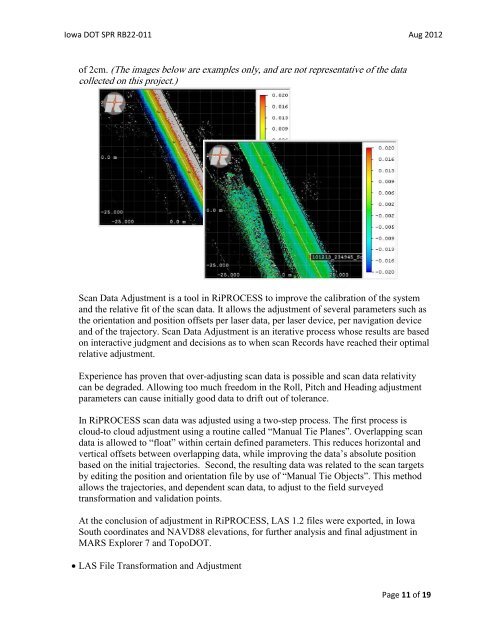
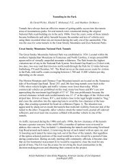
Iowa DOT SPR RB22-011 Aug 2012Scan Processing:• Vehicle Trajec<strong>to</strong>ry ProcessingTrajec<strong>to</strong>ry processing was performed using Applanix’s POSPac MMS version 5.3,Service Pack 3. Two base stations were fixed at their NAD83 (NAD83/1996) latitude andlongitude. Base station ellipsoid heights were fixed at their Geoid 09 modeled values,based upon their NAVD88 orthometric heights.Two methods <strong>of</strong> processing are available within the POSPac MMS suite, tightly or looselycoupled. In both solutions, the data is processed in both forward and backward directions<strong>to</strong> produce the optimal solution, smoothing the effect <strong>of</strong> GPS outages and otheraberrations in the data. In a tightly coupled solution the IMU data is used <strong>to</strong>gether withthe GPS data <strong>to</strong> produce a smoothed best estimate <strong>of</strong> trajec<strong>to</strong>ry (SBET) for the scanvehicle. During a complete GPS outage, the IMU data is not only used <strong>to</strong> carry thevehicle position, but also assists in regaining the GPS integer count when satellitereception is regained. A successful tightly coupled solution is always preferable <strong>to</strong> aloosely coupled solution. However, the tightly coupled solution currently only uses GPSdata and does not make use <strong>of</strong> any GLONASS data that may be available. The looselycoupled solution does make use <strong>of</strong> GLONASS data if available. However, the vehicletrajec<strong>to</strong>ry is based entirely upon the GNSS derived trajec<strong>to</strong>ry, with IMU data only beingused during a GNSS outage and in determining the orientation <strong>of</strong> the scanner. Thissolution would be used in the event that GPS data was <strong>of</strong> insufficient quality and a tightlycoupled solution was not possible. For these reasons, GPS and GLONASS data for boththe mobile platform and the base station(s) are always logged as a backup.Vehicle trajec<strong>to</strong>ries from the primary base station processed successfully as tightlycoupled solutions. As such, the backup base station data was not used in this survey.Trajec<strong>to</strong>ry quality reports are contained in Section 2 <strong>of</strong> this report. The reports arepresented as an overall trajec<strong>to</strong>ry, and further broken down by individual scan collectionsegments.• Scan Data ProcessingScan data was processed using Riegl’s RiPROCESS s<strong>of</strong>tware, version 1.4.15. InRiPROCESS raw scan data is time-matched with the SBET <strong>to</strong> produce trajec<strong>to</strong>ry-based,geo-referenced scan data. Scan records are typically collected in one mile segments on themainline, and for each ramp individually <strong>to</strong> allow for manageable data file sizes.Initially, each scan Record, consisting <strong>of</strong> overlapping data from Scanner 1 and Scanner 2,is compared by laser data height differencing. The laser difference range was set <strong>to</strong> +2 cm<strong>to</strong> -2 cm. This allows visual verification that scan records contain readily usable data.The image below-left, showing a rainbow effect <strong>of</strong> the laser differencing, is an example <strong>of</strong>data that is “scissored”. This scan record would be rejected in favor <strong>of</strong> the data in thesecond image below-right. Laser differencing in the second image indicates overlappingscan data is well within 2cm, and closer <strong>to</strong> 5mm <strong>of</strong> relative difference. Further processingis required for those scan Records that show laser differencing approaching and in excessPage 10 <strong>of</strong> 19
Iowa DOT SPR RB22-011 Aug 2012<strong>of</strong> 2cm. (The images below are examples only, and are not representative <strong>of</strong> the datacollected on this project.)Scan Data Adjustment is a <strong>to</strong>ol in RiPROCESS <strong>to</strong> improve the calibration <strong>of</strong> the systemand the relative fit <strong>of</strong> the scan data. It allows the adjustment <strong>of</strong> several parameters such asthe orientation and position <strong>of</strong>fsets per laser data, per laser device, per navigation deviceand <strong>of</strong> the trajec<strong>to</strong>ry. Scan Data Adjustment is an iterative process whose results are basedon interactive judgment and decisions as <strong>to</strong> when scan Records have reached their optimalrelative adjustment.Experience has proven that over-adjusting scan data is possible and scan data relativitycan be degraded. Allowing <strong>to</strong>o much freedom in the Roll, Pitch and Heading adjustmentparameters can cause initially good data <strong>to</strong> drift out <strong>of</strong> <strong>to</strong>lerance.In RiPROCESS scan data was adjusted using a two-step process. The first process iscloud-<strong>to</strong> cloud adjustment using a routine called “Manual Tie Planes”. Overlapping scandata is allowed <strong>to</strong> “float” within certain defined parameters. This reduces horizontal andvertical <strong>of</strong>fsets between overlapping data, while improving the data’s absolute positionbased on the initial trajec<strong>to</strong>ries. Second, the resulting data was related <strong>to</strong> the scan targetsby editing the position and orientation file by use <strong>of</strong> “Manual Tie Objects”. This methodallows the trajec<strong>to</strong>ries, and dependent scan data, <strong>to</strong> adjust <strong>to</strong> the field surveyedtransformation and validation points.At the conclusion <strong>of</strong> adjustment in RiPROCESS, LAS 1.2 files were exported, in IowaSouth coordinates and NAVD88 elevations, for further analysis and final adjustment inMARS Explorer 7 and TopoDOT.• LAS File Transformation and AdjustmentPage 11 <strong>of</strong> 19