User manual for VDR Explorer - Polaris-as.dk
User manual for VDR Explorer - Polaris-as.dk
User manual for VDR Explorer - Polaris-as.dk

You also want an ePaper? Increase the reach of your titles
YUMPU automatically turns print PDFs into web optimized ePapers that Google loves.
<strong>User</strong> Manual <strong>for</strong> <strong>VDR</strong> <strong>Explorer</strong><br />
For DM300 S-<strong>VDR</strong> and DM500 <strong>VDR</strong><br />
Document Number 9200294<br />
Version Number 1.2<br />
Date April 2007
Revision record<br />
<strong>User</strong> <strong>manual</strong> <strong>for</strong> <strong>VDR</strong> <strong>Explorer</strong><br />
Danelec Electronics A/S<br />
Version Date Description<br />
1.0 June 2006 Original issue of document<br />
1.1 December 2006 Documentation <strong>for</strong> <strong>VDR</strong> explorer Version 1.1. Support <strong>for</strong><br />
extraction to datab<strong>as</strong>e discontinued. Alarm display added.<br />
Other minor changes.<br />
1.2 April 2007 Minor revision. Description of Remote Backup h<strong>as</strong> been<br />
removed from this <strong>manual</strong>.<br />
9200294 V1.2 Page 2/73
Contents<br />
<strong>User</strong> <strong>manual</strong> <strong>for</strong> <strong>VDR</strong> <strong>Explorer</strong><br />
Danelec Electronics A/S<br />
REVISION RECORD ...........................................................................................................2<br />
1 SCOPE AND PURPOSE ..........................................................................................7<br />
1.1 References................................................................................................................7<br />
1.2 Terms and Abbreviations ..........................................................................................7<br />
2 SYSTEM OVERVIEW ...............................................................................................8<br />
2.1 Connecting the PC with a capsule or disc.................................................................9<br />
3 GUI DESCRIPTION ................................................................................................10<br />
3.1 After startup ............................................................................................................10<br />
3.1.1 Tool bar............................................................................................................11<br />
3.1.2 <strong>VDR</strong> <strong>Explorer</strong> status bar ..................................................................................11<br />
3.1.3 <strong>VDR</strong> <strong>Explorer</strong> play control area........................................................................11<br />
4 REPLAY OF DATA, SHORT GUIDE......................................................................12<br />
4.1.1 Play control ......................................................................................................13<br />
4.1.2 Tracks ..............................................................................................................13<br />
5 CONFIGURATION..................................................................................................14<br />
5.1 Creating a new configuration ..................................................................................14<br />
5.2 Adding new tab pages.............................................................................................14<br />
5.2.1 Tab page organizer..........................................................................................15<br />
5.3 Creating and moving graphical objects ...................................................................16<br />
5.3.1 Creating and moving panels ............................................................................16<br />
5.4 Configuration of graphical objects...........................................................................16<br />
5.4.1 Copy/p<strong>as</strong>t of graphical object configuration .....................................................17<br />
5.5 Configuration of Gauges .........................................................................................18<br />
5.5.1 Dial meter ............................................................................................................18<br />
5.5.2 Vertical bar.......................................................................................................20<br />
5.5.3 Horizontal bar...................................................................................................21<br />
5.5.4 Comp<strong>as</strong>s dial ...................................................................................................22<br />
5.5.5 Horizontal ruler.................................................................................................23<br />
5.5.6 Doppler log.......................................................................................................24<br />
5.5.7 Rudder indicator ..................................................................................................25<br />
5.5.8 Graph...............................................................................................................26<br />
5.5.9 Roll and pitch indicator ........................................................................................27<br />
5.6 Numeric data display...............................................................................................28<br />
5.6.1 General................................................................................................................28<br />
5.6.2 Colors ..............................................................................................................28<br />
5.6.3 Concatenation..................................................................................................28<br />
5.7 Paper strip...............................................................................................................29<br />
5.7.1 Data <strong>for</strong>mat ......................................................................................................29<br />
5.8 Configuration of data sources <strong>for</strong> objects................................................................30<br />
9200294 V1.2 Page 3/73
<strong>User</strong> <strong>manual</strong> <strong>for</strong> <strong>VDR</strong> <strong>Explorer</strong><br />
Danelec Electronics A/S<br />
5.8.1 Source .............................................................................................................30<br />
5.8.2 Use Factor (gauge only) ..................................................................................30<br />
5.8.3 Settings <strong>for</strong> analog data (alphanumeric data field only) ...................................31<br />
5.8.4 Settings <strong>for</strong> digital data ....................................................................................31<br />
5.8.5 Setting <strong>for</strong> serial data .......................................................................................32<br />
5.8.6 Relation between decoders stored in the library and the configuration............33<br />
5.8.7 Alarm settings ..................................................................................................33<br />
5.9 Default color definition.............................................................................................34<br />
5.10 Formatter syntax .....................................................................................................35<br />
6 <strong>VDR</strong> AND <strong>VDR</strong> EXPLORER CONFIGURATION MANAGEMENT ........................36<br />
6.1 <strong>VDR</strong> configuration management .............................................................................36<br />
6.2 <strong>VDR</strong> <strong>Explorer</strong> configuration management...............................................................36<br />
7 CONNECT DIALOG BOX.......................................................................................38<br />
7.1 Capsule...................................................................................................................38<br />
7.2 Backup ....................................................................................................................39<br />
7.3 <strong>VDR</strong> extraction........................................................................................................39<br />
7.4 Live .........................................................................................................................39<br />
8 DECODER LIBRARY .............................................................................................40<br />
8.1 Properties <strong>for</strong> a NMEA decoders.............................................................................40<br />
8.2 NMEA decoder library window ................................................................................41<br />
8.2.1 Drop down menus............................................................................................41<br />
8.2.2 Decoder library tree .........................................................................................42<br />
8.2.3 Decoder description .........................................................................................42<br />
8.3 NMEA Decoder Editor.............................................................................................43<br />
8.3.1 Drop down menus............................................................................................43<br />
8.3.2 Tool bar............................................................................................................44<br />
8.3.3 General buttons ...............................................................................................44<br />
8.3.4 Decoder in<strong>for</strong>mation.........................................................................................44<br />
8.3.5 Editor window...................................................................................................45<br />
8.3.6 Decoder test.....................................................................................................45<br />
9 EXTRACTOR..........................................................................................................46<br />
9.1.1 Track in<strong>for</strong>mation .............................................................................................46<br />
10 AUDIO EXPORT TOOL..........................................................................................48<br />
11 AUDIO SETTINGS TOOL.......................................................................................48<br />
11.1 P<strong>as</strong>sword protected audio.......................................................................................48<br />
12 DATA LOG .............................................................................................................48<br />
12.1 Configuration of data log .........................................................................................49<br />
12.1.1 Direct creations of columns..............................................................................49<br />
12.1.2 Indirect creations of columns ...........................................................................51<br />
9200294 V1.2 Page 4/73
<strong>User</strong> <strong>manual</strong> <strong>for</strong> <strong>VDR</strong> <strong>Explorer</strong><br />
Danelec Electronics A/S<br />
12.1.3 Organizing columns .........................................................................................52<br />
12.1.4 Maximum number of columns..........................................................................52<br />
12.2 Saving log data to a file...........................................................................................53<br />
12.2.1 Max file size .....................................................................................................53<br />
12.2.2 Sample interval ................................................................................................53<br />
12.3 Preferences.............................................................................................................53<br />
12.3.1 Directory path <strong>for</strong> log files ................................................................................53<br />
12.3.2 Disable data logging at connect.......................................................................53<br />
13 ALARM PANEL ......................................................................................................54<br />
13.1.1 E<strong>as</strong>y localization of alarms source...................................................................55<br />
13.2 Default setting <strong>for</strong> alarm panel ................................................................................55<br />
13.3 Configuration of objects <strong>for</strong> alarms..........................................................................56<br />
14 RELAY OF SERIAL OUTPUT TO OTHER APPLICATIONS .................................57<br />
14.1 Output port settings.................................................................................................57<br />
14.2 Configuration of serial output ..................................................................................58<br />
14.2.1 Merging of data ................................................................................................58<br />
14.3 Enable/Disable output .............................................................................................58<br />
14.4 Overflow on serial port ............................................................................................59<br />
14.5 Serial output and step .............................................................................................59<br />
15 AIS DATA DISPLAY...............................................................................................60<br />
15.1 AIS display tab ........................................................................................................60<br />
15.2 Selecting data source..............................................................................................61<br />
15.3 Using a AIS display tab ...........................................................................................62<br />
15.4 Symbols <strong>for</strong> Targets................................................................................................62<br />
15.5 Supported messages ..............................................................................................63<br />
16 SPECIAL FEATURES ............................................................................................64<br />
16.1 Floating windows.....................................................................................................64<br />
16.1.1 “Windows” drop down menu ............................................................................64<br />
16.2 Support <strong>for</strong> PC’s with lower screen resolution.........................................................64<br />
16.3 Vessel in<strong>for</strong>mation...................................................................................................64<br />
16.4 Play control .............................................................................................................64<br />
16.5 Full screen radar image ..........................................................................................64<br />
16.6 Full screen graph object..........................................................................................64<br />
17 NMEA SENTENCE FORMATTING SCRIPT LANGUAGE V1.4 ............................65<br />
17.1 Purpose...................................................................................................................65<br />
17.2 Language introduction.............................................................................................65<br />
17.3 Language example..................................................................................................65<br />
17.4 Bit function examples ..............................................................................................66<br />
17.5 Operators and reserved words................................................................................66<br />
17.5.1 Operators.........................................................................................................66<br />
17.5.2 Reserved words ...............................................................................................67<br />
17.6 Field Identifier .........................................................................................................67<br />
9200294 V1.2 Page 5/73
<strong>User</strong> <strong>manual</strong> <strong>for</strong> <strong>VDR</strong> <strong>Explorer</strong><br />
Danelec Electronics A/S<br />
17.7 ModBus functions....................................................................................................69<br />
17.8 Other functions........................................................................................................71<br />
17.8.1 L<strong>as</strong>t function.....................................................................................................71<br />
APPENDIX A S-<strong>VDR</strong> CONNING DISPLAY DEFAULT CONFIGURATION......................73<br />
9200294 V1.2 Page 6/73
1 Scope and purpose<br />
<strong>User</strong> <strong>manual</strong> <strong>for</strong> <strong>VDR</strong> <strong>Explorer</strong><br />
1.1 References<br />
1.2 Terms and Abbreviations<br />
<strong>User</strong> <strong>manual</strong> <strong>for</strong> <strong>VDR</strong> <strong>Explorer</strong><br />
Danelec Electronics A/S<br />
9200294 V1.2 Page 7/73
<strong>User</strong> <strong>manual</strong> <strong>for</strong> <strong>VDR</strong> <strong>Explorer</strong><br />
Danelec Electronics A/S<br />
2 System overview<br />
The <strong>VDR</strong> <strong>Explorer</strong> is an application designed <strong>for</strong> W2000 or XP. The <strong>VDR</strong> <strong>Explorer</strong> is able to<br />
replay data recorded by a DM300 S-<strong>VDR</strong> and DM500 <strong>VDR</strong>. The <strong>VDR</strong> <strong>Explorer</strong> can read data from<br />
the following sources:<br />
Source Hardware required<br />
Capsule Data from the capsule that h<strong>as</strong><br />
been removed from the <strong>VDR</strong><br />
Backup disc Data from a backup disc that<br />
h<strong>as</strong> been removed from the<br />
<strong>VDR</strong> (Note 1) or data created by<br />
the <strong>VDR</strong> explore backup<br />
application.<br />
<strong>VDR</strong> Extraction A file with <strong>VDR</strong> data<br />
downloaded from the <strong>VDR</strong>,<br />
capsule or a backup disc. It may<br />
also be a selection of data from<br />
another extraction<br />
Live Data transferred live from the<br />
<strong>VDR</strong> while recording.<br />
- A PC with Firewire port.<br />
- Firewire repeater with CAT 5<br />
interface<br />
- A mains to 12V DC adapter<br />
<strong>for</strong> the repeater is needed if a<br />
portable PC with 4-pin i/f is<br />
used<br />
- A stationary PC with a 6-pin<br />
Firewire port.<br />
- A Firewire repeater and a<br />
mains to 12V adapter is needed<br />
when a portable PC with a 4-pin<br />
Firewire port is used<br />
PC with an Ethernet port<br />
(10/100b<strong>as</strong>eT)<br />
Note 1) Data can be retrieved from a functional <strong>VDR</strong> with the backup disc in place by means of the<br />
web extractor facility and a PC with an Internet browser/Ethernet port. This is the simplest way of<br />
getting access to the <strong>VDR</strong> data.<br />
9200294 V1.2 Page 8/73
<strong>User</strong> <strong>manual</strong> <strong>for</strong> <strong>VDR</strong> <strong>Explorer</strong><br />
Danelec Electronics A/S<br />
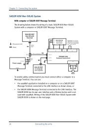
2.1 Connecting the PC with a capsule or disc<br />
Stationary<br />
PC<br />
Firewire<br />
cable<br />
6pin - 6pin<br />
FW repeater<br />
CAT5<br />
P/N 1001162<br />
Crossed CAT5<br />
RJ45 – RJ45<br />
Note 2<br />
Note 2) if the original cable is attached to the capsule, then use a straight CAT5 cable and a RJ45 coupler.<br />
Portable<br />
PC<br />
Firewire<br />
cable<br />
4pin - 6pin<br />
12VDC<br />
FW repeater<br />
CAT5<br />
P/N 1001162<br />
Mains<br />
adaptor<br />
P/N 1001163<br />
Crossed CAT5<br />
RJ45 – RJ45<br />
Note 2<br />
110-240VAC<br />
Note 2) if the original cable is attached to the capsule, then use a straight CAT5 cable and a RJ45 coupler.<br />
Stationary<br />
PC<br />
Firewire<br />
cable<br />
6pin - 6pin<br />
Backup disc<br />
Note) if the PC is unable to power the disc then use a repeater with a mains adaptor, see below.<br />
Portable<br />
PC<br />
Firewire<br />
cable<br />
4pin - 6pin<br />
12VDC<br />
FW repeater<br />
CAT5<br />
P/N 1001162<br />
Mains<br />
adaptor<br />
P/N 1001163<br />
Firewire<br />
cable<br />
6pin - 6pin<br />
110-240VAC<br />
Backup disc<br />
9200294 V1.2 Page 9/73
3 GUI description<br />
<strong>User</strong> <strong>manual</strong> <strong>for</strong> <strong>VDR</strong> <strong>Explorer</strong><br />
Danelec Electronics A/S<br />
3.1 After startup<br />
The <strong>VDR</strong> <strong>Explorer</strong> will upon startup use the default configuration (DefaultGuiConfig.xml)<br />
<strong>VDR</strong> <strong>Explorer</strong> window, dropdown menus (MS windows style)<br />
Tool bar<br />
Player control area<br />
Tab pages<br />
Player status bar<br />
The “window title bar” complies with the general standard <strong>for</strong> Microsoft GUI. The window title bar<br />
will display the name (if defined) of the current GUI configuration.<br />
<strong>VDR</strong> <strong>Explorer</strong> window dropdown menus:<br />
File->New: Creates a new (empty) <strong>VDR</strong> <strong>Explorer</strong> configuration<br />
File->Open: Opens an existing <strong>VDR</strong> <strong>Explorer</strong> configuration<br />
File->Save: Saves the current <strong>VDR</strong> <strong>Explorer</strong> configuration using the same name<br />
File->Save <strong>as</strong>: Save the current <strong>VDR</strong> <strong>Explorer</strong> configuration using a new name<br />
File->Recent files: Short cuts to the 4 most recent configurations, which have been opened or<br />
saved on the disc. The configuration, which h<strong>as</strong> been temporary downloaded e.g. from a <strong>VDR</strong> while<br />
playing live will not be included on the list.<br />
9200294 V1.2 Page 10/73
File->Exit: Exits the <strong>VDR</strong> <strong>Explorer</strong> program<br />
<strong>User</strong> <strong>manual</strong> <strong>for</strong> <strong>VDR</strong> <strong>Explorer</strong><br />
Danelec Electronics A/S<br />
Tools->Log: Displays the log <strong>for</strong> the <strong>VDR</strong> <strong>Explorer</strong> program. This is only used <strong>for</strong> troubleshooting.<br />
Tools->Audio: Opens the audio settings dialog box<br />
Tools->Connect: Opens the “connect” dialog box. The “connect” dialog box is used to select a data<br />
source <strong>for</strong> the <strong>VDR</strong> <strong>Explorer</strong> see section 7.<br />
Tools->Disconnect: Disconnects the <strong>VDR</strong> <strong>Explorer</strong> from the data source.<br />
Tools-><strong>VDR</strong> config management: The <strong>VDR</strong> <strong>Explorer</strong> is able to use some of the in<strong>for</strong>mation<br />
stored in a <strong>VDR</strong> <strong>for</strong> object labels see section 6.1<br />
Tools-><strong>VDR</strong> <strong>Explorer</strong> config management: The <strong>VDR</strong> <strong>Explorer</strong> is able to store its configuration<br />
together with source data and later retrieve this in<strong>for</strong>mation see section 6.2<br />
Tools->Decoder library: Opens the NMEA decoder library, see section 8.<br />
Tools->Extractor: Opens the Extractor dialog box, see section 9.<br />
Tools->Export audio <strong>as</strong> wave<br />
Tools->Options: Opens the options and settings dialog box.<br />
Mode->Configuration mode on: Sets the <strong>VDR</strong> <strong>Explorer</strong> in configuration mode.<br />
Mode->Configuration mode off: Exits the <strong>VDR</strong> <strong>Explorer</strong> from configuration mode.<br />
Monitor: Queue monitor used <strong>for</strong> troubleshooting only.<br />
3.1.1 Tool bar<br />
The tool bar contains short cuts (presented <strong>as</strong> icons) to the most common tools and functions.<br />
3.1.2 <strong>VDR</strong> <strong>Explorer</strong> status bar<br />
The <strong>VDR</strong> <strong>Explorer</strong> status bar contains in<strong>for</strong>mation regarding the current status of the <strong>VDR</strong><br />
<strong>Explorer</strong>. Additional in<strong>for</strong>mation regarding an object selected by the cursor (“on hover”) may be<br />
displayed to the left.<br />
3.1.3 <strong>VDR</strong> <strong>Explorer</strong> play control area<br />
The <strong>VDR</strong> <strong>Explorer</strong> play control area contains the main controls i.e. play, stop and pause. Some of<br />
the controls will be grayed out depending on the data source <strong>for</strong> the <strong>VDR</strong> <strong>Explorer</strong>. See also section<br />
4.1.1<br />
9200294 V1.2 Page 11/73
4 Replay of data, short guide<br />
<strong>User</strong> <strong>manual</strong> <strong>for</strong> <strong>VDR</strong> <strong>Explorer</strong><br />
Danelec Electronics A/S<br />
The <strong>VDR</strong> <strong>Explorer</strong> will automatically display the “Connect” dialog box when the program is<br />
started. This dialog is used <strong>for</strong> selecting a data source.<br />
To select a data source press “Connect”, consult section 7 <strong>for</strong> more details.<br />
It is highly recommended that a <strong>VDR</strong> explorer configuration that matches the <strong>VDR</strong> data is uploaded<br />
to the <strong>VDR</strong> when the <strong>VDR</strong> is installed, since this will enable any PC with the <strong>VDR</strong> <strong>Explorer</strong><br />
installed to replay data without any configuration work. If this dialog box appears then answer,<br />
“Yes”.<br />
9200294 V1.2 Page 12/73
<strong>User</strong> <strong>manual</strong> <strong>for</strong> <strong>VDR</strong> <strong>Explorer</strong><br />
Danelec Electronics A/S<br />
4.1.1 Play control<br />
The play control area contains the functions needed <strong>for</strong> replaying data. Two views are available,<br />
simple and advanced.<br />
Simple play control<br />
Advanced play control<br />
Click here to expand play control<br />
A tool tip with helpful in<strong>for</strong>mation will appear if the cursor hovers over a bottom <strong>for</strong> short period.<br />
Note) The tool tip is not available <strong>for</strong> disabled functions (buttons with symbols).<br />
4.1.2 Tracks<br />
A track is defined <strong>as</strong> an uninterrupted recording session. The <strong>VDR</strong> will create a new track if it is<br />
restarted. <strong>VDR</strong> data retrieved from a normally operating <strong>VDR</strong> will only contain one track.<br />
4.1.2.1 Goto button<br />
The “Goto” button will, if activated, set the slider to the position indicated in the input field below<br />
the button. A new value may be entered into the input field. The field will become red if the entered<br />
value is illegal or out of range. The icon left to the “Goto” button may be used to update the input<br />
field with the current position of the slider. This function may be used while the <strong>VDR</strong> <strong>Explorer</strong> is<br />
playing data. If you want to set a “mark” at an event you want to revert to, do the following. First<br />
click on the icon (left to the “Goto” button) to set the “mark”, later click on the Goto button and<br />
then “Play”.<br />
9200294 V1.2 Page 13/73
<strong>User</strong> <strong>manual</strong> <strong>for</strong> <strong>VDR</strong> <strong>Explorer</strong><br />
Danelec Electronics A/S<br />
5 Configuration<br />
The <strong>VDR</strong> <strong>Explorer</strong> must be in confirmation mode “Mode->Configuration Mode -<br />
On” be<strong>for</strong>e any change of configuration can be made.<br />
5.1 Creating a new configuration<br />
File->New<br />
Will create a new “empty” configuration.<br />
File->Open<br />
Is used to open an existing configuration e.g. a template. Use “File-Save <strong>as</strong>” to store the new<br />
configuration under another name.<br />
5.2 Adding new tab pages<br />
Right click on a tab <strong>for</strong> and existing page and then click on “Tab properties” and the “Tab page<br />
organizer will appear.<br />
9200294 V1.2 Page 14/73
5.2.1 Tab page organizer<br />
The Tab page organizer<br />
<strong>User</strong> <strong>manual</strong> <strong>for</strong> <strong>VDR</strong> <strong>Explorer</strong><br />
Danelec Electronics A/S<br />
The “Tab page organizer” is a tool <strong>for</strong> creating, deleting, hiding, naming and sorting of the tab<br />
pages.<br />
Click on “Add” and this menu will appear<br />
Type in the title <strong>for</strong> the new tab page and select a template from the list box. To start with add<br />
“<strong>VDR</strong> serial status tab” and a “<strong>VDR</strong> status tab”. After that add the pre configured conning display.<br />
It matches the S-<strong>VDR</strong> recommended standard setup. “Appendix A S-<strong>VDR</strong> conning display default<br />
configuration” shows the configuration <strong>for</strong> this page.<br />
9200294 V1.2 Page 15/73
<strong>User</strong> <strong>manual</strong> <strong>for</strong> <strong>VDR</strong> <strong>Explorer</strong><br />
Danelec Electronics A/S<br />
5.3 Creating and moving graphical objects<br />
The graphical objects on a tab page are organized in panels (columns). A graphical object often<br />
contains many elements hereafter called gauges.<br />
A proper tab page must be created be<strong>for</strong>e any graphical object can be created. Templates with one<br />
to four panels and one example have been made. (Right click on any tab <strong>for</strong> a tab page and then<br />
select ”Tab properties” opens the ”Tab Page Organizer” see section 5.2.<br />
A new graphical object is created on a panel by right clicking on a panel and then “Insert Object”.<br />
More objects within a panel will from a column.<br />
The position of an object within a panel may be changed i.e. the object may be moved up and down.<br />
Right click on the object and then click on “Object…-> Move up” or “Object…->Move down”<br />
A graphical object cannot be moved to another panel i.e. to the left or to the right. However there is<br />
a way around this limitation.<br />
1. Create a new instance of the object that h<strong>as</strong> to be moved on the desired location.<br />
2. Copy the configuration from the original object and p<strong>as</strong>te it onto the new object (see section<br />
5.4.1).<br />
3. Delete the original object.<br />
5.3.1 Creating and moving panels<br />
Right clicking on an existing panel and then select ”Insert panel” will create additional panels. More<br />
features <strong>for</strong> manipulating panels are found by right clicking on an existing panel and then selecting<br />
“Panel Properties”<br />
5.4 Configuration of graphical objects<br />
A graphical object contains one or more gauges <strong>for</strong> displaying data. The only exceptions are the<br />
“Numeric data display”, which contains 3 “objects” <strong>for</strong> displaying data in numerical <strong>for</strong>m or <strong>as</strong> text<br />
and the Paper strip object that is able to display serial data <strong>as</strong> text.<br />
The following graphical objects have been defined (consult section 15 regarding objects related to<br />
AIS data display):<br />
• Dial meter<br />
• Dual dial meter<br />
• Four Vertical bars<br />
• Two Horizontal bars<br />
• Comp<strong>as</strong>s dial<br />
• Horizontal ruler<br />
• Doppler log indicator<br />
• Dual Rudder indicator<br />
• Graph<br />
• Roll and Pitch indicator<br />
• Numeric data display<br />
• Small numeric data display<br />
9200294 V1.2 Page 16/73
• Paper strip<br />
<strong>User</strong> <strong>manual</strong> <strong>for</strong> <strong>VDR</strong> <strong>Explorer</strong><br />
Danelec Electronics A/S<br />
Right clicking on the object while the <strong>VDR</strong> <strong>Explorer</strong> is set into configuration mode opens the<br />
property dialog box <strong>for</strong> a graphical object.<br />
The first tap page called “General” contains the<br />
most common parameters <strong>for</strong> a graphical object.<br />
This page is slightly different <strong>for</strong> the “Numeric<br />
data display” see section 5.6.<br />
Title: Text that is common <strong>for</strong> the gauges<br />
displayed by the graphical object.<br />
Gauges: Checkboxes <strong>for</strong> enabling/disabling the<br />
display of gauges defined <strong>for</strong> that graphical object.<br />
Frame: The boundary of a graphical object is<br />
indicated (default) with four thin lines. A number<br />
of graphical objects may be grouped by removing<br />
the adjacent lines. This is purely a visual effect. A<br />
line may be disabled /enabled by double clinking<br />
on its position on the squared symbol located in<br />
this section.<br />
Source labels: (dial meter graphical object only):<br />
The label <strong>for</strong> the fields that displays the data in<br />
numeric <strong>for</strong>m<br />
The remaining tab pages are used <strong>for</strong> configuring<br />
the gauges defined <strong>for</strong> the graphical object.<br />
5.4.1 Copy/p<strong>as</strong>t of graphical object configuration<br />
The configuration from a graphical object may be copied and p<strong>as</strong>ted onto another identical<br />
graphical object.<br />
Copy configuration:<br />
Right click on the object with the desired configuration, and then click on “Copy Config”.<br />
P<strong>as</strong>te Configuration:<br />
Right click on the object that needs a new configuration, and then click on “P<strong>as</strong>te Configuration”<br />
The receiving graphical object must be identical to the original.<br />
9200294 V1.2 Page 17/73
5.5 Configuration of Gauges<br />
5.5.1 Dial meter<br />
<strong>User</strong> <strong>manual</strong> <strong>for</strong> <strong>VDR</strong> <strong>Explorer</strong><br />
Danelec Electronics A/S<br />
5.5.1.1 Labels<br />
Dial Title: Text located immediately over the dial<br />
meter.<br />
Unit: Text located inside the dial.<br />
Use peak indicator:<br />
The peak indicator will show the maximum<br />
reading <strong>for</strong> a specified time (peak timeout). This is<br />
useful e.g. when me<strong>as</strong>uring wind speed.<br />
5.5.1.2 Scale<br />
This section contain the parameters <strong>for</strong> controlling<br />
the geometry and resolution of the dial<br />
Start value: The start value corresponds to the<br />
most counterclockwise point on the dial.<br />
End value: The end value corresponds to the most<br />
clockwise point on the dial.<br />
Format:<br />
Format is used to define the <strong>for</strong>mat of the figures<br />
on the dial, see section 5.8.3.2.<br />
Show mathematical sign:<br />
The parameter controls whether figures on the dial<br />
are displayed signed or unsigned.<br />
Angle:<br />
Defines the extent of the dial.<br />
Rotation:<br />
The dial will per default be oriented like a typical<br />
speedometer in a car i.e. the axis of symmetry is<br />
vertical. The operator may change the orientation<br />
by entering a value other than 0 in this field.<br />
Resolution:<br />
This parameters control the graduation of the dial.<br />
9200294 V1.2<br />
Page 18/73
<strong>User</strong> <strong>manual</strong> <strong>for</strong> <strong>VDR</strong> <strong>Explorer</strong><br />
Danelec Electronics A/S<br />
5.5.1.3 Sources<br />
Primary: Input to the pointer <strong>for</strong> the dial meter.<br />
Secondary: Input to the secondary indicator <strong>for</strong> the dial meter. The secondary indicator is shown<br />
<strong>as</strong> a small triangle. The secondary indicator is typical used <strong>for</strong> displaying the “commanded value”<br />
while the main indicator shows the actual value.<br />
The “setup” button will open a dial box where the source data can be defined, see section 5.8<br />
5.5.1.4 Colors<br />
Parameters in this section control the appearance of the dial meter. The “set default” may be used to<br />
reset all the colors to the default settings (see section 5.9)<br />
9200294 V1.2 Page 19/73
5.5.2 Vertical bar<br />
<strong>User</strong> <strong>manual</strong> <strong>for</strong> <strong>VDR</strong> <strong>Explorer</strong><br />
Danelec Electronics A/S<br />
5.5.2.1 Labels<br />
A vertical bar h<strong>as</strong> two labels one at each end. One<br />
of them is typically used <strong>as</strong> description while the<br />
other indicates units.<br />
5.5.2.2 Scale<br />
Start value:<br />
The start value corresponds to the bottom of the<br />
bar.<br />
End value:<br />
The end value corresponds to the top of the bar.<br />
Mirror horizontally:<br />
Two adjacent bars are per default two symmetrical<br />
instances i.e. bar 1,2 and 3,4 <strong>for</strong>m two pairs. The<br />
operator may change this by “horizontally mirror”<br />
bar objects with odd number.<br />
Format:<br />
Format is used to define the <strong>for</strong>mat of the figures<br />
<strong>for</strong> the bar object, see section 5.8.3.2.<br />
Show mathematical sign:<br />
The parameter controls whether figures related to<br />
the bar object are displayed signed or unsigned.<br />
5.5.2.3 Sources<br />
Primary: Input to the main indicator <strong>for</strong> the bar<br />
object.<br />
Secondary: Input to the secondary indicator <strong>for</strong><br />
the bar object. The secondary indicator is shown<br />
<strong>as</strong> a small triangle. The secondary indicator is<br />
typically used <strong>for</strong> displaying the “commanded value” while the bar shows the actual value<br />
5.5.2.4 Colors<br />
Parameters in this section control the appearance of the bar object. The “set default” may be used to<br />
reset all the colors to the default settings (see section 5.9)<br />
9200294 V1.2 Page 20/73
<strong>User</strong> <strong>manual</strong> <strong>for</strong> <strong>VDR</strong> <strong>Explorer</strong><br />
Danelec Electronics A/S<br />
5.5.3 Horizontal bar<br />
The parameters <strong>for</strong> the horizontal bar correspond to<br />
the parameters <strong>for</strong> the vertical bar. An extra label<br />
(middle) h<strong>as</strong> been added.<br />
9200294 V1.2 Page 21/73
5.5.4 Comp<strong>as</strong>s dial<br />
5.5.4.1 Scale<br />
Format:<br />
Format is used to define the <strong>for</strong>mat of the figures<br />
on the comp<strong>as</strong>s dial, see section 5.8.3.2.<br />
5.5.4.2 Sources<br />
Primary:<br />
The primary data source controls the rotation of<br />
the comp<strong>as</strong>s dial, the typical input is “Heading”.<br />
<strong>User</strong> <strong>manual</strong> <strong>for</strong> <strong>VDR</strong> <strong>Explorer</strong><br />
Danelec Electronics A/S<br />
Secondary:<br />
The secondary (optional) data source controls a<br />
small triangle circling the comp<strong>as</strong>s dial. The<br />
typical secondary input is “Commanded Heading”.<br />
5.5.4.3 Colors<br />
The parameters in this section control the<br />
appearance of the comp<strong>as</strong>s dial. The “set default”<br />
button can be used to reset all the colors to the<br />
fault settings (see section 5.9)<br />
9200294 V1.2 Page 22/73
5.5.5 Horizontal ruler<br />
5.5.5.1 Labels<br />
A vertical bar h<strong>as</strong> 6 labels.<br />
5.5.5.2 Scale<br />
Star value:<br />
The start value corresponds to the far left point of<br />
the ruler.<br />
<strong>User</strong> <strong>manual</strong> <strong>for</strong> <strong>VDR</strong> <strong>Explorer</strong><br />
Danelec Electronics A/S<br />
End value:<br />
The end value corresponds to the far right point of<br />
the ruler.<br />
Format:<br />
Format is used to define the <strong>for</strong>mat of the figures<br />
on the ruler object, see section 5.8.3.2.<br />
Show mathematical sign:<br />
The parameter controls whether the figures related<br />
to the ruler object are displayed signed or<br />
unsigned.<br />
5.5.5.3 Sources<br />
Primary:<br />
Input to the primary indicator <strong>for</strong> the bar object.<br />
The main indicator is shown <strong>as</strong> a triangle above<br />
the ruler.<br />
Secondary:<br />
Input to the secondary indicator <strong>for</strong> the bar object. The secondary indicator is shown <strong>as</strong> a triangle<br />
below the ruler. The secondary indicator is typically used <strong>for</strong> displaying the “commanded value”<br />
while the primary indicator shows the actual value<br />
5.5.5.4 Colors<br />
Parameters in this section control the appearance of the ruler object. The “set default” can be used<br />
to reset all the colors to the default settings (see section 5.9)<br />
9200294 V1.2 Page 23/73
5.5.6 Doppler log<br />
5.5.6.1 Numeric Output<br />
Unit:<br />
Text displayed after numeric outputs e.g. KNT.<br />
<strong>User</strong> <strong>manual</strong> <strong>for</strong> <strong>VDR</strong> <strong>Explorer</strong><br />
Danelec Electronics A/S<br />
Format:<br />
Format is used to define the <strong>for</strong>mat of the numeric<br />
outputs, see section 5.8.3.2.<br />
Show mathematical sign:<br />
The parameter controls whether the numeric<br />
outputs are displayed signed or unsigned.<br />
5.5.6.2 Sources<br />
4 inputs may be applied to the Doppler log object.<br />
Longitudinal speed:<br />
Is shown <strong>as</strong> numeric data in the center of the<br />
object<br />
Stern transverse speed:<br />
Is shown <strong>as</strong> numeric data at top of the object.<br />
Aft transverse speed:<br />
Is shown <strong>as</strong> numeric data at bottom of the object.<br />
Relative wind direction:<br />
Is shown <strong>as</strong> a triangle circling the center of the<br />
object.<br />
5.5.6.3 Colors<br />
Parameters in this section control the appearance<br />
of the object. The “set default” can be used to reset<br />
all the colors to the default settings (see section<br />
5.9)<br />
9200294 V1.2 Page 24/73
5.5.7 Rudder indicator<br />
5.5.7.1 Labels<br />
Title:<br />
Text shown beneath the rudder indicator.<br />
5.5.7.2 Scale<br />
Rudder Max Angle:<br />
This parameter controls the extent of the dial <strong>for</strong><br />
the object. It is recommended that a value equal<br />
to the maximum rudder angle <strong>for</strong> the vessel is<br />
used.<br />
<strong>User</strong> <strong>manual</strong> <strong>for</strong> <strong>VDR</strong> <strong>Explorer</strong><br />
Danelec Electronics A/S<br />
Show Mathematical Sign:<br />
The parameter controls whether figures on the dial<br />
are displayed signed or unsigned.<br />
5.5.7.3 Sources<br />
Primary:<br />
The primary data source controls the pointer; the<br />
typical input is data from the rudder angle sensor.<br />
Secondary:<br />
The secondary (optional) data source controls a<br />
small triangle circling the dial. The typical<br />
secondary input is “Commanded rudder angle”.<br />
5.5.7.4 Colors<br />
Parameters in this section control the appearance of the object. The “set default” can be used to<br />
reset all the colors to the default settings (see section 5.9)<br />
9200294 V1.2 Page 25/73
5.5.8 Graph<br />
<strong>User</strong> <strong>manual</strong> <strong>for</strong> <strong>VDR</strong> <strong>Explorer</strong><br />
Danelec Electronics A/S<br />
5.5.8.1 Graph type<br />
This section is used <strong>for</strong> defining the input to the Xcoordinate<br />
<strong>for</strong> the graph object.<br />
Time/Y graphs:<br />
The primary and secondary will be used <strong>as</strong> Ycoordinate<br />
<strong>for</strong> two independent graphs. The time<br />
will be used <strong>as</strong> X-coordinate <strong>for</strong> both graphs.<br />
X/Y graph: The primary input will be used <strong>for</strong> the<br />
X-coordinate and the secondary <strong>for</strong> the Ycoordinate.<br />
5.5.8.2 Resolution<br />
This section is used <strong>for</strong> defining the resolution of<br />
the graph(s). Small values <strong>for</strong> “Time Span” and<br />
“Sample Interval” derive a graph with high<br />
resolution while high values derive a graph that<br />
covers a large time span.<br />
5.5.8.3 Labels<br />
Label:<br />
Labels <strong>for</strong> numeric output.<br />
Unit:<br />
Text displayed after numeric output and Y-axis,<br />
X-axis if X/Y graph is selected.<br />
5.5.8.4 Scale<br />
This section is used <strong>for</strong> defining resolution and<br />
<strong>for</strong>mat of figures <strong>for</strong> the Y-axis and the X-axis if<br />
X/Y graph is selected.<br />
5.5.8.5 Colors<br />
Parameters in this section control the colors of the<br />
graph. The “set default” can be used to reset all the<br />
colors to the default settings (see section 5.9)<br />
9200294 V1.2 Page 26/73
5.5.9 Roll and pitch indicator<br />
5.5.9.1 Gauge<br />
Title:<br />
Text shown above the gauge.<br />
<strong>User</strong> <strong>manual</strong> <strong>for</strong> <strong>VDR</strong> <strong>Explorer</strong><br />
Danelec Electronics A/S<br />
Type:<br />
Used to select the gauge type (roll or pitch). Roll is<br />
default <strong>for</strong> gauge 1 and pitch is default <strong>for</strong> gauge 2<br />
5.5.9.2 Scale<br />
Format:<br />
Format is used to define the <strong>for</strong>mat of the numeric<br />
outputs, see section 5.8.3.2.<br />
Show Mathematical Sign:<br />
The parameter controls whether the figures on the<br />
dial are displayed signed or unsigned.<br />
5.5.9.3 Source<br />
Primary:<br />
The data source controls the rotation of the ship<br />
shaped indicator in the middle of the gauge; the<br />
typical input is data from the roll and pith sensor<br />
respectively.<br />
5.5.9.4 Colors<br />
Parameters in this section control the appearance<br />
of the object. The “set default” can be used to reset<br />
all the colors to the default settings (see section<br />
5.9)<br />
9200294 V1.2 Page 27/73
5.6 Numeric data display<br />
5.6.1 General<br />
The Numeric Data Display does not display any<br />
gauges. Three smaller “objects” <strong>for</strong> displaying<br />
numeric data or text are displayed instead. These<br />
smaller objects are called “Alphanumeric data<br />
fields.<br />
<strong>User</strong> <strong>manual</strong> <strong>for</strong> <strong>VDR</strong> <strong>Explorer</strong><br />
Danelec Electronics A/S<br />
5.6.2 Colors<br />
The color of the label text <strong>for</strong> a “Graphical<br />
Standard Object” is determined by the default<br />
color definition (Text/Outline Color) see section<br />
5.9. The “Primary indicator color” is used <strong>as</strong> the<br />
default <strong>for</strong> the displayed data but may be changed<br />
by the operator.<br />
5.6.3 Concatenation<br />
A number of Numeric Data Displays may be<br />
concatenated by removing adjacent lines (see<br />
section 5.4).<br />
9200294 V1.2 Page 28/73
<strong>User</strong> <strong>manual</strong> <strong>for</strong> <strong>VDR</strong> <strong>Explorer</strong><br />
Danelec Electronics A/S<br />
5.7 Paper strip<br />
The Paper strip object is designed to display serial<br />
data <strong>as</strong> text e.g. data that is sent to a line printer. It<br />
can also be used to monitor NMEA data.<br />
5.7.1 Data <strong>for</strong>mat<br />
The object is able to display data using three<br />
different <strong>for</strong>mats:<br />
• ASCII<br />
• NMEA<br />
• Binary. Binary is displayed <strong>as</strong><br />
“hexadecimal”<br />
9200294 V1.2 Page 29/73
<strong>User</strong> <strong>manual</strong> <strong>for</strong> <strong>VDR</strong> <strong>Explorer</strong><br />
Danelec Electronics A/S<br />
5.8 Configuration of data sources <strong>for</strong> objects<br />
This dialog box is common <strong>for</strong> all gauges and <strong>for</strong> the alphanumeric data display with few<br />
exceptions. This dialog is opened by clicking on the “Setup” button located in the “Source” section<br />
on the property pages <strong>for</strong> an object.<br />
5.8.1 Source<br />
The source section is used to select the proper source <strong>for</strong> the gauge. A gauge/data field may be<br />
disabled by selecting “No Source” i.e. no other parameters will be <strong>for</strong>gotten if already configured.<br />
5.8.2 Use Factor (gauge only)<br />
The operator may apply a factor (multiplier) to the original data. E.g. knots may be converted to<br />
m/s.<br />
5.8.2.1 Add to log (alphanumeric data field only)<br />
The in<strong>for</strong>mation displayed in the data field will also be added to the log if this box is checked (see<br />
section 12).<br />
9200294 V1.2 Page 30/73
<strong>User</strong> <strong>manual</strong> <strong>for</strong> <strong>VDR</strong> <strong>Explorer</strong><br />
Danelec Electronics A/S<br />
5.8.3 Settings <strong>for</strong> analog data (alphanumeric data field only)<br />
5.8.3.1 Heading and trailing text:<br />
Heading and trailing text may be configured to<br />
change according to the numbering value <strong>for</strong><br />
data.<br />
5.8.3.2 Formatter string<br />
See section 5.10.<br />
5.8.3.3 Test data <strong>for</strong>mat<br />
A “test utility” is located beneath the<br />
configuration fields.<br />
5.8.4 Settings <strong>for</strong> digital data<br />
5.8.4.1 Use alternative values (gauge only)<br />
Used to define alternative numeric values <strong>for</strong> active and inactive state, default (if box is unchecked)<br />
is 1 and 0.<br />
5.8.4.2 Use text from <strong>VDR</strong> configuration<br />
These parameters are used to define what text is <strong>as</strong>sociated to active and inactive state e.g. “Open”<br />
and “Closed”. This in<strong>for</strong>mation is normally available from the <strong>VDR</strong> configuration and can be used<br />
by the <strong>VDR</strong> <strong>Explorer</strong> <strong>as</strong> it is.<br />
9200294 V1.2 Page 31/73
5.8.5 Setting <strong>for</strong> serial data<br />
5.8.5.1 Decoding section<br />
Contains in<strong>for</strong>mation about the currently<br />
selected decoder script:<br />
Edit: will open the decoder script editor.<br />
The editor is used <strong>for</strong> creating a new<br />
decoder script or <strong>for</strong> editing the currently<br />
selected one. A “*” after the name denotes<br />
that the decoder h<strong>as</strong> been edited but not<br />
stored in the library yet. But it is strongly<br />
recommended that an edited decoder<br />
always be given a new name and that<br />
modification is described!<br />
Edit: Will open the decoder editor, see<br />
section 8.3.<br />
<strong>User</strong> <strong>manual</strong> <strong>for</strong> <strong>VDR</strong> <strong>Explorer</strong><br />
Danelec Electronics A/S<br />
Save in library:<br />
Used to save the decoder script in the library if it h<strong>as</strong> been changed. Se section 5.8.6<br />
Library:<br />
Will open the decoder script library from where the most commonly used decoder scripts can be<br />
selected see section 8.<br />
Use checksum:<br />
NMEA strings not containing correct checksum in<strong>for</strong>mation will be ignored if this box is checked.<br />
Use timeout:<br />
The appearance of gauge/data field will be affected when no new data is resolved within a specified<br />
time if this box is checked<br />
- For gauges<br />
The indicator will disappear.<br />
- For alphanumeric data field:<br />
An additional menu “Action” is displayed <strong>for</strong> an alphanumeric data field.<br />
The operator may chose between:<br />
• Delete data: The data field is blanked<br />
• Dimming: Dimming of the text in the data field<br />
• Timeout: “Timeout” will displayed in the data field<br />
9200294 V1.2 Page 32/73
<strong>User</strong> <strong>manual</strong> <strong>for</strong> <strong>VDR</strong> <strong>Explorer</strong><br />
Danelec Electronics A/S<br />
5.8.6 Relation between decoders stored in the library and the configuration<br />
Decoder Library<br />
Decoder #1<br />
Decoder #2<br />
Decoder #3<br />
Decoder #4<br />
.<br />
.<br />
.<br />
New decoder<br />
.<br />
.<br />
.<br />
Decoder #n<br />
1<br />
3<br />
5a<br />
2<br />
<strong>VDR</strong> <strong>Explorer</strong><br />
Configuration<br />
Gauge #1:<br />
Copy of<br />
Decoder #3<br />
Gauge #2:<br />
Copy of<br />
Decoder #2<br />
Gauge #3:<br />
Edited copy of<br />
Decoder #4<br />
Step 1) Decoder #2 is selected <strong>for</strong> Gauge #1<br />
Step 2) Decoder #3 is selected <strong>for</strong> Gauge #2<br />
Step 3) Decoder #4 is selected <strong>for</strong> Gauge #3<br />
Step 4) the decoder <strong>for</strong> gauge #3 is modified <strong>for</strong> some re<strong>as</strong>on.<br />
The operator now h<strong>as</strong> two options:<br />
Step 5a) Store the new decoder under a new name in the library i.e. use the “Save library” function<br />
see section 5.8.5.1.<br />
Step 5b) leave at it is i.e. a new decoder is created but is not stored in the library.<br />
This message will appear if the operator tries to replace a decoder that is not stored in the library<br />
5.8.7 Alarm settings<br />
Parameters relevant <strong>for</strong> the alarm display see section 13<br />
9200294 V1.2 Page 33/73<br />
4
5.9 Default color definition<br />
<strong>User</strong> <strong>manual</strong> <strong>for</strong> <strong>VDR</strong> <strong>Explorer</strong><br />
Danelec Electronics A/S<br />
The global colors define the over all color-scheme used <strong>for</strong> the graphical data display(s).<br />
• The background color is the color of the window used <strong>for</strong> a graphical data display. The<br />
background color will be visible because there is a small space between objects (unless they<br />
are merged).<br />
• The Object Frame Color indicates the border of an object.<br />
• Object background Color is background color used <strong>for</strong> objects.<br />
• “Text/outline color” is color <strong>for</strong> static text (e.g. labels) and <strong>for</strong> outline of most gauges.<br />
Changes to Global color take affect immediately after “OK” or “Apply” is selected even when the<br />
<strong>VDR</strong> <strong>Explorer</strong> is not in configuration mode.<br />
The default colors are the colors of dynamic elements in a graphical data display e.g. the indicator<br />
<strong>for</strong> a dial meter. Changes to default colors will only take affect <strong>for</strong> new objects. The colors <strong>for</strong> an<br />
existing object may be set to new default colors by right clicking on the object (in configurations<br />
mode) and select Object->Set to Default Colors.<br />
9200294 V1.2 Page 34/73
<strong>User</strong> <strong>manual</strong> <strong>for</strong> <strong>VDR</strong> <strong>Explorer</strong><br />
Danelec Electronics A/S<br />
5.10 Formatter syntax<br />
Figures displayed in an alphanumeric data field may be <strong>for</strong>matted, i.e. the number of digit after the<br />
decimal point and leading zeroes may be defined.<br />
The <strong>for</strong>matter syntax is identical to the syntax defined <strong>for</strong> <strong>for</strong>matting output from a NMEA decoder.<br />
E.g.: The figures 7.5 and 10 will be displayed like this depending on the <strong>for</strong>matter.<br />
Formatter 7.5 10<br />
0 7 10<br />
0.0 7.5 10.0<br />
000 007 010<br />
9200294 V1.2 Page 35/73
<strong>User</strong> <strong>manual</strong> <strong>for</strong> <strong>VDR</strong> <strong>Explorer</strong><br />
Danelec Electronics A/S<br />
6 <strong>VDR</strong> and <strong>VDR</strong> <strong>Explorer</strong> configuration management<br />
The <strong>VDR</strong> <strong>Explorer</strong> will use in<strong>for</strong>mation from both the <strong>VDR</strong> configuration (if available) and a <strong>VDR</strong><br />
<strong>Explorer</strong> configuration. The <strong>VDR</strong> configuration contains useful in<strong>for</strong>mation about what is<br />
connected to the <strong>VDR</strong>. In<strong>for</strong>mation from the <strong>VDR</strong> configuration may enable the <strong>VDR</strong> <strong>Explorer</strong> to<br />
e.g. use the name “SI02 Input from GPS” <strong>for</strong> serial input port #2 rather than just the default name“<br />
SI02”.<br />
These functions are normally not needed except <strong>for</strong> “Tools-><strong>VDR</strong> <strong>Explorer</strong> config management-><br />
Save <strong>VDR</strong> <strong>Explorer</strong>-configuration to source”. This function is used <strong>for</strong> storing the final <strong>VDR</strong><br />
<strong>Explorer</strong> configurations in the capsule. This will enable any PC with the <strong>VDR</strong> <strong>Explorer</strong> installed to<br />
replay data from that <strong>VDR</strong> correctly.<br />
6.1 <strong>VDR</strong> configuration management<br />
Tools-><strong>VDR</strong> config management->Load <strong>VDR</strong> configuration from file<br />
Facilitates load of a alternative <strong>VDR</strong> configuration from a file.<br />
Tools-><strong>VDR</strong> config management->Load <strong>VDR</strong> configuration from source<br />
Reloads the original <strong>VDR</strong> configuration from the source.<br />
Tools-><strong>VDR</strong> config management->Set <strong>VDR</strong> configuration to default<br />
Restores the <strong>VDR</strong> configuration to default i.e. all labels will hereafter correspond to what is printed<br />
on the data interface modules e.g. “SI02”.<br />
Tools-><strong>VDR</strong> config management->Save <strong>VDR</strong> configuration from source to file<br />
Saves <strong>VDR</strong> configuration present on the source to a file.<br />
Tools-><strong>VDR</strong> config management->Display <strong>VDR</strong> configuration from source<br />
Displays the <strong>VDR</strong> configuration found at the source to which to <strong>VDR</strong> <strong>Explorer</strong> is currently<br />
connected.<br />
6.2 <strong>VDR</strong> <strong>Explorer</strong> configuration management<br />
A few special commands related to <strong>VDR</strong> <strong>Explorer</strong> configuration management are included here.<br />
Commonly used commands like Open, Save etc. are included in the “File” dropdown menu.<br />
Tools-><strong>VDR</strong> <strong>Explorer</strong> config management-> Load <strong>VDR</strong> <strong>Explorer</strong>-configuration from source<br />
Tool <strong>for</strong> reloading of a <strong>VDR</strong> <strong>Explorer</strong> configuration from the data source<br />
1) <strong>VDR</strong> (live playing): The configuration stored in the capsule will be loaded.<br />
2) Capsule/backup disc: The configuration stored in the capsule/on the backup disc will be loaded.<br />
3) Extracted data: A dialog box will enable the user to load the original or the user defined<br />
configuration.<br />
Tools-><strong>VDR</strong> <strong>Explorer</strong> config management-> Save <strong>VDR</strong> <strong>Explorer</strong>-configuration to source<br />
Tool <strong>for</strong> saving the <strong>VDR</strong> <strong>Explorer</strong> configuration at the data source.<br />
1) <strong>VDR</strong> (live playing): The current <strong>VDR</strong> <strong>Explorer</strong> configuration is stored in the capsule and on the<br />
backup disc via the <strong>VDR</strong>. The <strong>VDR</strong> <strong>Explorer</strong> must be connected <strong>as</strong> “M<strong>as</strong>ter”.<br />
9200294 V1.2 Page 36/73
<strong>User</strong> <strong>manual</strong> <strong>for</strong> <strong>VDR</strong> <strong>Explorer</strong><br />
Danelec Electronics A/S<br />
2) Capsule/backup disc: The <strong>VDR</strong> <strong>Explorer</strong> is not able to write to a capsule/backup disc and is<br />
consequently not able to save the <strong>VDR</strong> <strong>Explorer</strong> configuration at the source if data source is a<br />
capsule/backup disc<br />
3) Extracted data: The operator may store a “user defined” configuration together with the extracted<br />
data. The original <strong>VDR</strong> <strong>Explorer</strong> configuration (if present) will not be overwritten.<br />
9200294 V1.2 Page 37/73
7 Connect dialog box<br />
Tools->connect will open the connect dialog box.<br />
<strong>User</strong> <strong>manual</strong> <strong>for</strong> <strong>VDR</strong> <strong>Explorer</strong><br />
Danelec Electronics A/S<br />
The connect dialog box is used <strong>for</strong> connecting the <strong>VDR</strong> <strong>Explorer</strong> to a data source. Five types of<br />
data sources are supported:<br />
• A capsule<br />
• A backup disc<br />
• <strong>VDR</strong> extraction<br />
• Live from a <strong>VDR</strong><br />
The connect dialog box will change according to the selected type of data source.<br />
7.1 Capsule<br />
“Capsules online” window:<br />
The “Capsules online” window displays a small symbol <strong>for</strong> each capsule, physically connected to<br />
the <strong>VDR</strong> <strong>Explorer</strong> PC via the Firewire interface. A capsule is selected by left clicking on its<br />
symbol. (Note: It is unusual to connect more the one capsule, but up to three capsules may be<br />
connected simultaneous if needed)<br />
“Refresh” button:<br />
Forces the <strong>VDR</strong> <strong>Explorer</strong> to scan the Firewire <strong>for</strong> capsules and update the window.<br />
“Analyze” button and “track in<strong>for</strong>mation” window:<br />
The selected capsule may be analyzed <strong>for</strong> its content. The result is displayed in the “track<br />
in<strong>for</strong>mation window”. For more in<strong>for</strong>mation about tracks consult section 9.1.1<br />
“Connect” button:<br />
9200294 V1.2 Page 38/73
<strong>User</strong> <strong>manual</strong> <strong>for</strong> <strong>VDR</strong> <strong>Explorer</strong><br />
Danelec Electronics A/S<br />
Establishes a connection from the <strong>VDR</strong> <strong>Explorer</strong> software to the selected capsule. This may take a<br />
few seconds.<br />
“Cancel”<br />
Closes the window.<br />
7.2 Backup<br />
Two kinds of backup discs are recognized:<br />
- A disc that h<strong>as</strong> been removed from a <strong>VDR</strong><br />
- Disc with data made by the <strong>VDR</strong> Remote backup utility (large backup)<br />
The dialog <strong>for</strong> connecting a Backup Disc corresponds to the dialog <strong>for</strong> connecting a capsule,<br />
described in section 7.1.<br />
7.3 <strong>VDR</strong> extraction<br />
“Browse” button:<br />
Will open a standard file browser dialog box, which is used to locate and open a file containing a<br />
<strong>VDR</strong> extraction (file extension is .vee).<br />
“Analyze” button and “track in<strong>for</strong>mation” window:<br />
The selected file may be analyzed <strong>for</strong> its content. The result is displayed in the “track in<strong>for</strong>mation<br />
window”. For more in<strong>for</strong>mation about tracks consult section 9.1.1.<br />
“Connect” button:<br />
Connects the <strong>VDR</strong> <strong>Explorer</strong> to the selected datab<strong>as</strong>e.<br />
“Cancel” button:<br />
Closes the “Connect dialog” window.<br />
7.4 Live<br />
“Connect to IP” field:<br />
The IP address of the <strong>VDR</strong> must be entered here.<br />
“Get in<strong>for</strong>mation” button:<br />
Tests the connection to the <strong>VDR</strong> with the IP address displayed in the “Connect to IP” field. Status<br />
in<strong>for</strong>mation from the <strong>VDR</strong> will (if the tested <strong>VDR</strong> is online) be displayed in the <strong>VDR</strong> “In<strong>for</strong>mation<br />
field”.<br />
“Connect” button:<br />
Connects the <strong>VDR</strong> <strong>Explorer</strong> to a <strong>VDR</strong> with the IP address displayed in the ”Connect to IP” field.<br />
“Cancel” button:<br />
Closes the “Connect dialog” window.<br />
9200294 V1.2 Page 39/73
<strong>User</strong> <strong>manual</strong> <strong>for</strong> <strong>VDR</strong> <strong>Explorer</strong><br />
Danelec Electronics A/S<br />
8 Decoder library<br />
The NMEA decoder library is used to organize the NMEA decoders. A NMEA decoder is a small<br />
script, which describes how in<strong>for</strong>mation shall be decoded and retrieved from a specific NMEA<br />
sentence. The syntax <strong>for</strong> the script language is described in section 17. A short description is<br />
available under “Help->Help Topics” in the decoder editor.<br />
Tools->decoder library will open the decoder library.<br />
8.1 Properties <strong>for</strong> a NMEA decoders<br />
Sentence <strong>for</strong>matter:<br />
A NMEA decoder is only able to retrieve in<strong>for</strong>mation from one specific NMEA sentence.<br />
A typical NMEA decoder is only able to retrieve in<strong>for</strong>mation from one field in a NMEA sentence.<br />
Most NMEA sentences contain many fields, hence a number of decoders may be needed <strong>for</strong><br />
retrieving all the in<strong>for</strong>mation from one sentence.<br />
Decoder group:<br />
A NMEA decoder belongs to a group, all decoders in the same group are stored in the same folder.<br />
Groups have been defined corresponding to the data items to be recorded (IEC 61996 section 4.6)<br />
e.g. speed (4.6.3) or heading (4.6.4). The user may establish new groups.<br />
Decoder name:<br />
A decoder must be <strong>as</strong>signed a name. The name must be unique within the decoder group.<br />
9200294 V1.2 Page 40/73
<strong>User</strong> <strong>manual</strong> <strong>for</strong> <strong>VDR</strong> <strong>Explorer</strong><br />
Danelec Electronics A/S<br />
(Write) protected decoders:<br />
A number of standard decoders (protected decoders) have been defined. These decoders are write<br />
protected and cannot be changed or deleted by the user. However the operator may use one of these<br />
decoders <strong>as</strong> a template <strong>for</strong> a new decoder.<br />
Sub library file:<br />
The <strong>VDR</strong> <strong>Explorer</strong> will at startup “compile” the library from a number of library files each<br />
containing a number of decoders. The standard decoders are stored in one file and another file is<br />
used to store the user-defined decoders. More library files <strong>for</strong> specific purposes may be added.<br />
Decoder output:<br />
The output from a decoder may behave like analog data, digital data or a text string. This<br />
in<strong>for</strong>mation may be described <strong>for</strong> a decoder. However this in<strong>for</strong>mation is only in<strong>for</strong>mative and will<br />
not be used by the <strong>VDR</strong> <strong>Explorer</strong>.<br />
8.2 NMEA decoder library window<br />
8.2.1 Drop down menus<br />
File->import:<br />
Imports decoders from an external file. The imported decoders will be added to the user defined sub<br />
library file.<br />
File->export:<br />
Exports decoders to an external file.<br />
File->Save in library:<br />
Saves decoder in library.<br />
File->Close:<br />
Closes the window. Corresponds to cancel.<br />
Edit->New decoder:<br />
Adds a new decoder to the library.<br />
Edit->New folder:<br />
Adds a new folder to the library.<br />
Edit->Copy:<br />
Makes a copy of the selected decoder.<br />
Edit->Edit:<br />
Opens the decoder edit window.<br />
Edit->Rename:<br />
Renames the selected decoder or folder.<br />
9200294 V1.2 Page 41/73
Edit->Delete:<br />
Deletes the selected decoder or folder.<br />
<strong>User</strong> <strong>manual</strong> <strong>for</strong> <strong>VDR</strong> <strong>Explorer</strong><br />
Danelec Electronics A/S<br />
8.2.2 Decoder library tree<br />
The decoder library tree is shown to the left. The “radio buttons” at the top are used to define how<br />
the library is organized.<br />
A pop up menu will appear if the user right clicks on<br />
a folder or a decoder. This menu will enable the user<br />
to add, rename, copy and delete folders and decoders.<br />
For “Import to Folder” consult section 8.2.1<br />
Note: It is only possible to create a new “root folder”<br />
by right clicking on the empty space beneath the<br />
“library tree”.<br />
Pop up <strong>for</strong> decoder<br />
Pop up <strong>for</strong> folder<br />
8.2.3 Decoder description<br />
The properties <strong>for</strong> the selected decoder, are shown in decoder description located to the right in<br />
NMEA decoder library window consult section 8.1 <strong>for</strong> more details..<br />
9200294 V1.2 Page 42/73
<strong>User</strong> <strong>manual</strong> <strong>for</strong> <strong>VDR</strong> <strong>Explorer</strong><br />
Danelec Electronics A/S<br />
8.3 NMEA Decoder Editor<br />
The NMEA decoder editor may either be opened from the decoder library or from the settings menu<br />
<strong>for</strong> a gauge/alphanumeric data field.<br />
8.3.1 Drop down menus<br />
File->Save <strong>as</strong>:<br />
Closes the editor window and opens the NMEA decoder library window where the new name and<br />
folder (group) may be defined. This item is only present if the editor is called from the NMEA<br />
decoder library.<br />
File->Close:<br />
Closes the editor window. The user will be prompted <strong>for</strong> unsaved changes.<br />
Edit->Undo<br />
Edit->Redo<br />
Edit->Cut<br />
9200294 V1.2 Page 43/73
Edit->Copy<br />
Edit->P<strong>as</strong>te<br />
Edit->Delete<br />
Commands <strong>for</strong> the Editor<br />
<strong>User</strong> <strong>manual</strong> <strong>for</strong> <strong>VDR</strong> <strong>Explorer</strong><br />
Danelec Electronics A/S<br />
Tools->Insert symbol<br />
A menu with symbols normally not found on a keyboard will be displayed.<br />
Help->Help topics:<br />
A description of the decoder script language will be displayed.<br />
8.3.2 Tool bar<br />
A tool bar is located below the drop down menus. The tool bar contains short cuts (icons) to the<br />
most commonly used items from the drop down menus.<br />
8.3.3 General buttons<br />
“OK” button:<br />
Changes made will be stored, the editor window is hereafter closed. The previous version of the<br />
decoder is overwritten. It is not possible to overwrite the decoders that are supplied with the <strong>VDR</strong><br />
<strong>Explorer</strong>.<br />
“Cancel” button:<br />
Closes the editor window, any changes made will be ignored and lost.<br />
“Save As” button:<br />
The editor window will close. Changes made may be saved if the “Save As” button is in the<br />
decoder library are activated. This will give the operator an opportunity to save the changes using a<br />
new name/folder while maintaining the previous version of the decoder.<br />
The save <strong>as</strong> button is only enabled if the editor is opened from the library (i.e. disabled when<br />
opened from the GUI configurator).<br />
8.3.4 Decoder in<strong>for</strong>mation<br />
Decoder name:<br />
See section 8.1<br />
Decoder output:<br />
See section 8.1<br />
Decoder description:<br />
A description of the decoder may be included (recommended).<br />
9200294 V1.2 Page 44/73
<strong>User</strong> <strong>manual</strong> <strong>for</strong> <strong>VDR</strong> <strong>Explorer</strong><br />
Danelec Electronics A/S<br />
8.3.5 Editor window<br />
A script defining the decoder shall be entered in the NMEA decoder window. The “sentence<br />
<strong>for</strong>matter field” derives in<strong>for</strong>mation from the “search <strong>for</strong>” statement in the decoder script. The full<br />
name <strong>for</strong> the NMEA sentence will be displayed if the sentence <strong>for</strong>matter is known.<br />
“Help->Help topics” shows a short description of the script language. Section 17 contains an<br />
extensive description of the script language.<br />
8.3.6 Decoder test<br />
A decoder may be tested against an NMEA sentence if the test decoder button is activated. Two<br />
things happen when the test button is activated:<br />
1. The script will be compiled i.e. the syntax is checked. The text in the “NMEA test sentence”<br />
field will not influence this. The test will only continue if the compilation is successful.<br />
2. The NMEA decoder will decode the NMEA sentence shown in “NMEA test sentence” field.<br />
This is of course only meaningful if the NMEA sentence <strong>for</strong>matter in the test sentence<br />
matches the NMEA sentence <strong>for</strong>matter in the decoders search <strong>for</strong> statement. The data output<br />
and the trend output will be displayed upon a successful test.<br />
8.3.6.1 “NMEA test sentence” field<br />
The user may enter a test sentence in this field. Copy/p<strong>as</strong>te from e.g. the serial monitor may be<br />
used. The 10 most recent test sentences will be saved.<br />
9200294 V1.2 Page 45/73
<strong>User</strong> <strong>manual</strong> <strong>for</strong> <strong>VDR</strong> <strong>Explorer</strong><br />
Danelec Electronics A/S<br />
9 Extractor<br />
The Extractor is used to retrieve data from a data source to a datab<strong>as</strong>e. The <strong>VDR</strong> <strong>Explorer</strong> must be<br />
connected to a date source (not live from a <strong>VDR</strong>) be<strong>for</strong>e the Extractor tool can be opened.<br />
9.1.1 Track in<strong>for</strong>mation<br />
The track in<strong>for</strong>mation <strong>for</strong> the currently selected capsule or backup disc is displayed in this window.<br />
A track is defined <strong>as</strong> an uninterrupted recording session. This typical corresponds to a time period<br />
where the <strong>VDR</strong> w<strong>as</strong> not interrupted e.g. by a restart. However, other events may divide a recording<br />
into two tracks e.g. a bad record (checksum error) on the disc. There will only exist one track in the<br />
capsule or on the backup disc <strong>for</strong> a <strong>VDR</strong> system that h<strong>as</strong> been running uninterrupted and faultless<br />
<strong>for</strong> more than 13 hours.<br />
One or more tracks must be selected be<strong>for</strong>e the extraction process can start. A track is selected by<br />
right clicking anywhere on the text line <strong>for</strong> that track (except on the checkbox). The sliders on the<br />
blue bar may be used to reduce the amount of data used from the selected track.<br />
9200294 V1.2 Page 46/73
<strong>User</strong> <strong>manual</strong> <strong>for</strong> <strong>VDR</strong> <strong>Explorer</strong><br />
Danelec Electronics A/S<br />
The check boxes are used <strong>for</strong> indicating whether a track shall be included or excluded from the<br />
extraction. Only check marked tracks will be included.<br />
Extraction target:<br />
Displays the currently selected (if any) extraction target.<br />
“Extract” button:<br />
Starts the extraction process.<br />
“Close” button:<br />
Closes the window.<br />
Overview <strong>for</strong> the extraction process step by step:<br />
1. Connect to a capsule or backup disc using the connect tool.<br />
2. Open the extractor tool.<br />
3. Select, and optional trim the duration of tracks to be extracted.<br />
4. Start extraction process using the “Extract” button.<br />
Extracting all data from a capsule will take approximately 20 minutes and require 6G byte of disc<br />
space.<br />
9200294 V1.2 Page 47/73
<strong>User</strong> <strong>manual</strong> <strong>for</strong> <strong>VDR</strong> <strong>Explorer</strong><br />
Danelec Electronics A/S<br />
10 Audio Export Tool<br />
The operator may use the Audio Export Tool <strong>for</strong> generation of wave files, which <strong>for</strong> example may<br />
be analyzed or improved.<br />
The Audio Export Tool is almost identical to the Extractor Tool.<br />
Check boxes <strong>for</strong> selecting channels have been included. Individual wave files (mono) will be<br />
generated <strong>for</strong> each selected audio channel i.e. the audio will not be mixed. Further, tracks will not<br />
be merged. A naming convention h<strong>as</strong> been defined <strong>for</strong> the files.<br />
.wav<br />
Mapping of “input” to ch#<br />
VHF 1 ch1<br />
VHF 2 ch2<br />
MIC 1/2 ch3<br />
MIC 3/4 ch4<br />
MIC 5/6 ch5<br />
e.g.:<br />
Captains’ voice Track 2 ch2.wav<br />
Export of p<strong>as</strong>sword-protected audio is only possible if the p<strong>as</strong>sword is known.<br />
11 Audio settings tool<br />
The Audio settings tool contains check boxes <strong>for</strong> selecting and directing audio channels to the left<br />
or right speaker.<br />
A m<strong>as</strong>ter volume is included.<br />
The compression effect is useful when listening to recordings with a high dynamic range<br />
11.1 P<strong>as</strong>sword protected audio<br />
Audio can be p<strong>as</strong>sword protected and replay of audio disabled. The operator may enable audio<br />
replay by opening the Audio Settings Tool and enter the correct p<strong>as</strong>sword.<br />
12 Data Log<br />
The data log function is able to log data from selected objects into a CSV file. The data log function<br />
is <strong>as</strong>sociated to a special tab page. The data log tab page is established like any other tab page<br />
• The <strong>VDR</strong> <strong>Explorer</strong> must be set in configuration mode.<br />
• Right click on a tab <strong>for</strong> a tab page and then select “tab properties”, this will open the “tab<br />
page organizer”.<br />
9200294 V1.2 Page 48/73
<strong>User</strong> <strong>manual</strong> <strong>for</strong> <strong>VDR</strong> <strong>Explorer</strong><br />
Danelec Electronics A/S<br />
• Click on “add” and select the “Data Logger Tab”.<br />
12.1 Configuration of data log<br />
Columns may be created by two methods.<br />
12.1.1 Direct creations of columns<br />
• The <strong>VDR</strong> <strong>Explorer</strong> must be in configuration mode.<br />
• Right click on the title bar <strong>for</strong> the columns next to “Timestamp”.<br />
• Click on “add column” and a list of relevant objects appear.<br />
Continue on next page …<br />
9200294 V1.2 Page 49/73
• Select an object and click on OK<br />
<strong>User</strong> <strong>manual</strong> <strong>for</strong> <strong>VDR</strong> <strong>Explorer</strong><br />
Danelec Electronics A/S<br />
• Enter the title press ok and a new column is created.<br />
9200294 V1.2 Page 50/73
<strong>User</strong> <strong>manual</strong> <strong>for</strong> <strong>VDR</strong> <strong>Explorer</strong><br />
Danelec Electronics A/S<br />
12.1.2 Indirect creations of columns<br />
• The <strong>VDR</strong> <strong>Explorer</strong> must be in configuration mode.<br />
• Open the properties dialog <strong>for</strong> an object that is able to input data to the data log (short<br />
standard object and standard object)<br />
• Check “Add to log” and a new column is created.<br />
• Change the title if needed. Right click on the title, select “Column Title” and enter a new<br />
title.<br />
9200294 V1.2 Page 51/73
<strong>User</strong> <strong>manual</strong> <strong>for</strong> <strong>VDR</strong> <strong>Explorer</strong><br />
Danelec Electronics A/S<br />
12.1.3 Organizing columns<br />
The <strong>VDR</strong> <strong>Explorer</strong> must be (with few exception) in configuration mode.<br />
Right clicking on the title <strong>for</strong> column will open a menu with miscellaneous commands.<br />
In general the width and order of the column can be changed in the same manner <strong>as</strong> <strong>for</strong> many other<br />
Windows programs e.g. using ”click, drag and drop” on the column title can be used to rearrange<br />
columns.<br />
12.1.4 Maximum number of columns<br />
The maximum number of columns that can be handled depends the PC. A PC that meets the general<br />
requirements <strong>for</strong> the <strong>VDR</strong> <strong>Explorer</strong> will be able to handle 25 columns without any noticeable<br />
per<strong>for</strong>mance degradation.<br />
9200294 V1.2 Page 52/73
<strong>User</strong> <strong>manual</strong> <strong>for</strong> <strong>VDR</strong> <strong>Explorer</strong><br />
Danelec Electronics A/S<br />
12.2 Saving log data to a file<br />
The program will store the data to a user defined output file.<br />
The library path <strong>for</strong> the log files is defined by the preferences <strong>for</strong> the <strong>VDR</strong> <strong>Explorer</strong> see section<br />
12.3<br />
12.2.1 Max file size<br />
Maximum file size is user defined. Data logging will stop when the file is full. The file may then be<br />
reset (or renamed/moved using Windows Explore).<br />
12.2.2 Sample interval<br />
The sample interval is user defined. F<strong>as</strong>t sampling (small intervals) requires lot of disc space.<br />
12.3 Preferences<br />
12.3.1 Directory path <strong>for</strong> log files<br />
The library path <strong>for</strong> the log files are defined by the preferences <strong>for</strong> the <strong>VDR</strong> <strong>Explorer</strong> (<strong>VDR</strong><br />
<strong>Explorer</strong> main window, Options->Preferences->Directory settings).<br />
12.3.2 Disable data logging at connect<br />
Data logging without explicit acknowledge from the operator can be inhibited (<strong>VDR</strong> <strong>Explorer</strong> main<br />
window, Options->Preferences->Advanced).<br />
On: The operator must start data logging <strong>manual</strong>ly.<br />
Off: Data logging will start automatically if configuration with “data logger enable” is<br />
loaded.<br />
Prompt: (Default) The operator will be prompted be<strong>for</strong>e data logging will start.<br />
9200294 V1.2 Page 53/73
13 Alarm panel<br />
<strong>User</strong> <strong>manual</strong> <strong>for</strong> <strong>VDR</strong> <strong>Explorer</strong><br />
Danelec Electronics A/S<br />
Selecting “Tools->Alarm Panel” or clicking on the icon on the Player window tool bar will<br />
activate the alarm window.<br />
Acknowledge all alarms:<br />
This function will acknowledge all alarms on the list. An alarm may be acknowledged individually<br />
by clicking on the icon <strong>for</strong> that alarm.<br />
Delete all alarms:<br />
The function will delete all alarms from the list. An alarm may be deleted individually by clicking<br />
on the icon <strong>for</strong> that alarm.<br />
Acknowledge audio:<br />
This function will mute the audio until a new alarm is generated.<br />
Options->Disable sound:<br />
This option will mute the audio related to the alarms panel completely.<br />
Options->Disable popup:<br />
This option will prevent the alarm window from popping up when a new alarm is generated.<br />
9200294 V1.2 Page 54/73
<strong>User</strong> <strong>manual</strong> <strong>for</strong> <strong>VDR</strong> <strong>Explorer</strong><br />
Danelec Electronics A/S<br />
13.1.1 E<strong>as</strong>y localization of alarms source<br />
Double clicking on the text <strong>for</strong> an alarm will bring the tab page from where the alarm is generated<br />
to the front. The object that h<strong>as</strong> generated the alarm will fl<strong>as</strong>h red <strong>for</strong> a few seconds.<br />
13.2 Default setting <strong>for</strong> alarm panel<br />
The default settings <strong>for</strong> the alarm panel may be set from the Player’s main window by selecting<br />
“Option->Settings”.<br />
9200294 V1.2 Page 55/73
<strong>User</strong> <strong>manual</strong> <strong>for</strong> <strong>VDR</strong> <strong>Explorer</strong><br />
Danelec Electronics A/S<br />
13.3 Configuration of objects <strong>for</strong> alarms<br />
Most objects can generate an alarm to the alarm panel.<br />
The parameters <strong>for</strong> generating alarms is located together with the other parameter related to a data<br />
source see section 5.8.<br />
23<br />
The example above shows how an alarm will be generated if the wind speed is above 23knt.<br />
Active:<br />
The object will only generate alarms if this box is checked.<br />
Alarm text:<br />
The text that will be written in the alarm window.<br />
Level Alarm:<br />
An alarm will be generated if the output above or alternatively under a specific level.<br />
For serial communication, ple<strong>as</strong>e note that the trend output from a NMEA decoder is used <strong>for</strong> the<br />
alarm system.<br />
Alarm on new data:<br />
An alarm will be generated every time data is received (only applicable <strong>for</strong> serial data).<br />
9200294 V1.2 Page 56/73
<strong>User</strong> <strong>manual</strong> <strong>for</strong> <strong>VDR</strong> <strong>Explorer</strong><br />
Danelec Electronics A/S<br />
14 Relay of serial output to other applications<br />
The <strong>VDR</strong> <strong>Explorer</strong> is able to relay serial data to other applications.<br />
14.1 Output port settings<br />
An output port on the PC <strong>for</strong> the serial data is needed and must be configured. These parameters are<br />
included in the <strong>VDR</strong> <strong>Explorer</strong>’s preferences (Options->Preference->Port Settings).<br />
9200294 V1.2 Page 57/73
<strong>User</strong> <strong>manual</strong> <strong>for</strong> <strong>VDR</strong> <strong>Explorer</strong><br />
Danelec Electronics A/S<br />
14.2 Configuration of serial output<br />
The <strong>VDR</strong> <strong>Explorer</strong> must be in configuration mode.<br />
A click on “Tools->Serial output” will open the tool <strong>for</strong> configuring the sources of the serial output.<br />
The operator may select a number of data sources and one output port.<br />
14.2.1 Merging of data<br />
The program is designed to handle NMEA sentences i.e. two sentences will not be interleaved but<br />
sent one at a time. The program may fail to relay ASCI or binary data depending of the properties of<br />
the data.<br />
14.3 Enable/Disable output<br />
An icon on the <strong>VDR</strong> <strong>Explorer</strong> tool bar can be used to enabled/disable the serial output. This can<br />
be done while the <strong>VDR</strong> <strong>Explorer</strong> is playing/replaying data.<br />
9200294 V1.2 Page 58/73
<strong>User</strong> <strong>manual</strong> <strong>for</strong> <strong>VDR</strong> <strong>Explorer</strong><br />
Danelec Electronics A/S<br />
14.4 Overflow on serial port<br />
The serial output port may overflow if the combined inputs exceed the capacity of the output port.<br />
The operator will be warned if this happens. The operator may suppress the message. This will be in<br />
<strong>for</strong>ce until output is disabled and then enabled.<br />
14.5 Serial output and step<br />
The <strong>VDR</strong> <strong>Explorer</strong> is able to generate serial output while stepping. However the output port may be<br />
congested and steps may take very long time to process.<br />
9200294 V1.2 Page 59/73
<strong>User</strong> <strong>manual</strong> <strong>for</strong> <strong>VDR</strong> <strong>Explorer</strong><br />
Danelec Electronics A/S<br />
15 AIS data display<br />
There are eight objects designed <strong>for</strong> displaying AIS data:<br />
• AIS display<br />
• AIS display (small)<br />
• AIS own ship info<br />
• AIS target info<br />
• AIS target list (.5x1)<br />
• AIS target list (.5x2)<br />
• AIS target list (1x1)<br />
• AIS target list (1x2)<br />
The figures following an ”AIS target list” refer to the size of the object where 1x1 is the typical size<br />
of a graphical object.<br />
Notice that AIS data display object may be mixed with other object on a tab page.<br />
15.1 AIS display tab<br />
A default AIS data display h<strong>as</strong> been defined which contains a useful combination of AIS object.<br />
This tab page is created like any other tab page see section 5.2<br />
9200294 V1.2 Page 60/73
<strong>User</strong> <strong>manual</strong> <strong>for</strong> <strong>VDR</strong> <strong>Explorer</strong><br />
Danelec Electronics A/S<br />
The AIS tab page is composed of the following objects;<br />
• One AIS display<br />
• One AIS Own ship info<br />
• Four AIS target Info<br />
• One AIS target list (.5x2)<br />
15.2 Selecting data source<br />
“Tools->Setup AIS Data Input” will open the “AIS data settings” tool.<br />
AIS data settings tool<br />
Select the serial channel to which the AIS is connected.<br />
9200294 V1.2 Page 61/73
15.3 Using a AIS display tab<br />
<strong>User</strong> <strong>manual</strong> <strong>for</strong> <strong>VDR</strong> <strong>Explorer</strong><br />
Danelec Electronics A/S<br />
The most important feature of the AIS data display is the ability to <strong>as</strong>sign a label to and get<br />
in<strong>for</strong>mation about a target of interest. This is simply done by clicking either directly on the target on<br />
the AIS display or on the label field <strong>for</strong> the target in the AIS target list. An AIS target info object<br />
will be <strong>as</strong>signed to the target when this is done.<br />
E.g.: On the AIS display tab shown above targets “A” and “B” have been selected.<br />
A target may be deselected by clicking on the target again. The number of “AIS target objects” on<br />
an “AIS display tab” determines the number of targets that can be selected simultaneously. “First in<br />
first out” applies if the number of selected targets exceeds the number of “AIS target objects”.<br />
15.4 Symbols <strong>for</strong> Targets<br />
AIS Standard target:<br />
B<strong>as</strong>e station:<br />
9200294 V1.2 Page 62/73
Aids to navigation:<br />
Aircraft:<br />
15.5 Supported messages<br />
1 - Position report<br />
2 - Position report<br />
3 - Position report<br />
4 - B<strong>as</strong>e station report<br />
5 - Static and voyage related data<br />
6 - Binary addressed message<br />
8 - Binary broadc<strong>as</strong>t message<br />
9 - Standard SAR aircraft position report<br />
12 - Addressed safety related message<br />
14 - Safety related broadc<strong>as</strong>t message<br />
18 - Standard Cl<strong>as</strong>s B equipment position report<br />
19 - Extended Cl<strong>as</strong>s B equipment position report<br />
21 - Aids-to-navigation report<br />
22 - Channel management<br />
24 - Cl<strong>as</strong>s B "CS" static data report<br />
<strong>User</strong> <strong>manual</strong> <strong>for</strong> <strong>VDR</strong> <strong>Explorer</strong><br />
Danelec Electronics A/S<br />
9200294 V1.2 Page 63/73
16 Special features<br />
<strong>User</strong> <strong>manual</strong> <strong>for</strong> <strong>VDR</strong> <strong>Explorer</strong><br />
Danelec Electronics A/S<br />
16.1 Floating windows<br />
Note: This new feature h<strong>as</strong> been designed <strong>for</strong> experienced users. Using floating windows in<br />
configuration mode may be confusing.<br />
A tab page may be detached from the <strong>VDR</strong> <strong>Explorer</strong>s main window. This is either done by “click,<br />
drag and drop” or “double clicking” on the tab <strong>for</strong> a tab page.<br />
Right clicking on the top bar <strong>for</strong> a floating window will open a menu with items <strong>for</strong> manipulating<br />
the window e.g. making it full screen.<br />
Double clicking on the top bar <strong>for</strong> floating window will revert it to a tab page. A floating window<br />
will also revert to a tab page if the corner of the window is aligned with the corner first tab in the<br />
<strong>VDR</strong> <strong>Explorer</strong>’s main window.<br />
16.1.1 “Windows” drop down menu<br />
A drop down menu (Windows) h<strong>as</strong> been added to the menu bar <strong>for</strong> the <strong>VDR</strong> <strong>Explorer</strong>s main<br />
window. The window selected from this menu will be brought to the front.<br />
16.2 Support <strong>for</strong> PC’s with lower screen resolution<br />
The <strong>VDR</strong> <strong>Explorer</strong> Pro is designed <strong>for</strong> 1280x1024 and above, however a PC with lower screen<br />
resolution may be used with minor inconvenience.<br />
16.3 Vessel in<strong>for</strong>mation<br />
Complete vessel in<strong>for</strong>mation is normally not displayed. “View->Vessel in<strong>for</strong>mation” may be used<br />
to open/close a window <strong>for</strong> displaying complete vessel in<strong>for</strong>mation.<br />
One “data item” related to Vessel in<strong>for</strong>mation (vessel name is default) is displayed next to the tool<br />
bar <strong>for</strong> the <strong>VDR</strong> <strong>Explorer</strong>’s main window.<br />
16.4 Play control<br />
“View->Play Control” may be used to hide/show the Play Control. The Play Control may also be<br />
moved around (click, drag and drop).<br />
16.5 Full screen radar image<br />
Full screen radar image is entered and exited by double clicking on the image.<br />
16.6 Full screen graph object<br />
A double click on a graph object will expand it to full screen. A full screen graph will return to<br />
normal size upon a double click.<br />
9200294 V1.2 Page 64/73
<strong>User</strong> <strong>manual</strong> <strong>for</strong> <strong>VDR</strong> <strong>Explorer</strong><br />
Danelec Electronics A/S<br />
17 NMEA sentence <strong>for</strong>matting script language V1.4<br />
17.1 Purpose<br />
The purpose of this language is to e<strong>as</strong>ily match a given NMEA sentence and <strong>for</strong>mat it to human<br />
readable text. This implies that both pattern matching ability and string <strong>for</strong>matting ability must be a<br />
part of the language. The resulting human readable text will have a value <strong>as</strong>sociated with it. This<br />
value is used <strong>for</strong> the trend indicator and is most likely taken from the NMEA sentence.<br />
17.2 Language introduction<br />
Matching and <strong>for</strong>matting a NMEA sentence consists of applying a small compiled program to a<br />
NMEA sentence. The output from this program will be the <strong>for</strong>matted string and an optional value.<br />
In this context a program is a compiled set of statements in the NMEA sentence <strong>for</strong>matting<br />
language. The source <strong>for</strong> a program in this language consists of a sequence of statements. Each<br />
statement will be executed in the order they are written; hence the language is a straight-line<br />
language. If a statement fails, the program will exit.<br />
17.3 Language example<br />
The syntax and semantics of the language is best shown by use of an example. For an exact<br />
description of the language see the Grammar chapter 3.<br />
The following NMEA sentence is to be <strong>for</strong>matted:<br />
Field no: | 1 | 2 |3| 4 |5| 6 | 7<br />
Sentence: $GPGLL,5536.1234,N,01244.1234,E,123456.78,A*1B<br />
into the following result: “N 55°36.123” and the <strong>as</strong>sociated trend value “5536.1234” . Running the<br />
following program does this:<br />
// This is a comment and have no effect on the program<br />
Search <strong>for</strong> “GLL”<br />
If #7 “A”<br />
print “GPS failed”<br />
Stop<br />
EndIf<br />
Print #3<br />
Print “ “<br />
Print #2 1:2<br />
Print “°”<br />
Print #2 3:6 F00.000<br />
Trend #2<br />
The first line is a comment and h<strong>as</strong> no effect on the program, but can be a useful aid when<br />
developing decoders in the <strong>for</strong>matting language. The second line “Search <strong>for</strong> “GLL”” identifies<br />
which NMEA id this program is valid <strong>for</strong>. The third line uses an “if“ construct to test if field 7<br />
contains the text “A”. If this is the c<strong>as</strong>e, the text “GPS failed” is printed and the program stops. If<br />
9200294 V1.2 Page 65/73
<strong>User</strong> <strong>manual</strong> <strong>for</strong> <strong>VDR</strong> <strong>Explorer</strong><br />
Danelec Electronics A/S<br />
not, the program continues onto line three. The next few lines consists of “print” statements on<br />
field identifiers and strings. The h<strong>as</strong>h mark “#” indicates a field identifier:<br />
#field [range] [<strong>for</strong>mat]<br />
Where “field” indicates the field number, “range” the range of characters to use and “<strong>for</strong>mat”<br />
how the number should be <strong>for</strong>matted.<br />
Continuous “print” operations can be concatenated into one “print” sentence resulting in a more<br />
compact program:<br />
Search <strong>for</strong> “GLL”<br />
If #7 “A”<br />
print “GPS failed”<br />
Stop<br />
EndIf<br />
Print #3 “ “ #2 1:2 “°” #2 3:6 F00.000<br />
Trend #2<br />
The l<strong>as</strong>t line identifies the field which will be used <strong>as</strong> the trend value.<br />
17.4 Bit function examples<br />
The following fictive NMEA sentence is used:<br />
Field no: | 1 | 2 |3| 4<br />
Sentence: $XXYYY,DEADBEEF01,N,A*1B<br />
search <strong>for</strong> "YYY"<br />
if bit(#2,2) = 1<br />
print "bit 2"<br />
stop<br />
endif<br />
if bit(#2,1) = 1<br />
print "bit 1"<br />
endif<br />
The output of this program applied to the above NMEA sentence is: “bit 1” since bit 2 is not set. Bit<br />
number is counted from the right hand side and begins at position 1. Hence bit 24-28 is the “B”.<br />
17.5 Operators and reserved words<br />
17.5.1 Operators<br />
The following operators are valid in “if” statements:<br />
Operator Meaning Valid types on the right side of operator<br />
= Equality Strings, integers and real numbers<br />
9200294 V1.2 Page 66/73
<strong>User</strong> <strong>manual</strong> <strong>for</strong> <strong>VDR</strong> <strong>Explorer</strong><br />
Danelec Electronics A/S<br />
Inequality Strings, integers and real numbers<br />
= Less or equal Integers and real numbers<br />
< Less than Integers and real numbers<br />
> Greater than Integers and real numbers<br />
The left side of an operator must be a field.<br />
17.5.2 Reserved words<br />
The following words are reserved:<br />
Reserved word Meaning<br />
Print Prints a field or a string<br />
Search <strong>for</strong> Identifies the NMEA id the program is valid <strong>for</strong><br />
If Beginning of an “if” statement. “if” statement<br />
cannot be nested.<br />
EndIf Identifies that the “if” statement ends here<br />
Stop Stop the program keeping result<br />
Break Break the program with no result<br />
Trend Set trend value<br />
Bit(Field, Bit no.) Returns 1 if a bit is set in Field, 0 if not. Field must be<br />
a hex string. If bit does not exist it returns –1.<br />
Mbit(Field, bit no.) Returns 1 if a bit is set in a modbus field, 0 if not.<br />
Field must be a modbus string. If bit does not exist it<br />
returns –1.<br />
Mreg(Field, reg no.) Returns modbus register if the register exists in the<br />
modbus field. Field must be a modbus string. If<br />
register does not exist it returns –1.<br />
MSreg(Field, reg no.) Returns a signed Modbus register if the register exists<br />
in the Modbus field. Field must be a Modbus string.<br />
If register does not exist it returns 0. Use Mreg to the<br />
register existance.<br />
L<strong>as</strong>t(Field, count) Returns the l<strong>as</strong>t “count” characters of a field.<br />
Reserved words are not c<strong>as</strong>e sensitive.<br />
17.6 Field Identifier<br />
The h<strong>as</strong>h mark “#” indicates a field identifier:<br />
#field [range] [<strong>for</strong>mat]<br />
Where “field” indicates the field number beginning from 1.<br />
The “range” is optional and identifies the range of characters to use. The syntax is “x:y” where “x”<br />
is the first character to use (unless “y” is negative) and “y” is the number of characters. If “x” is out<br />
9200294 V1.2 Page 67/73
<strong>User</strong> <strong>manual</strong> <strong>for</strong> <strong>VDR</strong> <strong>Explorer</strong><br />
Danelec Electronics A/S<br />
of range then the program is terminated and an error is printed. If “y” is out of range then the<br />
program will print to the end of the field.<br />
If “y” is negative then the characters are selected from left. First to be printed is “x-y+1” and l<strong>as</strong>t<br />
character to be printer is “x”<br />
Example:<br />
Field no: | 1 | 2 |3| 4<br />
Sentence: $XXYYY,123456,N,A*1B<br />
search <strong>for</strong> "YYY"<br />
print #2 3:-2<br />
The printed result will be “23”.<br />
If “x” is negative then the first character to print is selected from the right. Example:<br />
Field no: | 1 | 2 |3| 4<br />
Sentence: $XXYYY,123456,N,A*1B<br />
search <strong>for</strong> "YYY"<br />
print #2 -4:3<br />
This printed result will be “345”.<br />
To print everything but the l<strong>as</strong>t two characters of field 2:<br />
Field no: | 1 | 2 |3| 4<br />
Sentence: $XXYYY,123456,N,A*1B<br />
search <strong>for</strong> "YYY"<br />
print #2 -3:-99<br />
Will print “1234”<br />
The “<strong>for</strong>mat” field is optional and similar to the one used in Visual B<strong>as</strong>ic. The maximum length of<br />
a <strong>for</strong>matter will be limited to 10 characters, including the decimal point.<br />
E.g.:<br />
Formatter Data to display<br />
- 14.75 0.336 -17 278<br />
F0 14 0 -17 278<br />
F00.00 14.75 00.34 -17.00 278.00<br />
F0.000 14.750 0.336 -17.000 278.000<br />
F000.0 014.8 000.3 -017.0 278.0<br />
9200294 V1.2 Page 68/73
<strong>User</strong> <strong>manual</strong> <strong>for</strong> <strong>VDR</strong> <strong>Explorer</strong><br />
Danelec Electronics A/S<br />
A000.0 014.8 000.3 017.0 278.0<br />
N000.0 -014.8 -000.3 017.0 -278.0<br />
The will be no default <strong>for</strong>matting of fields.<br />
By replacing the “F” with an “A” the result will be <strong>for</strong>matted into an absolute value. The following<br />
syntax is not allowed: “F0.” and “F.0”<br />
17.7 ModBus functions<br />
These functions are only relevant in conjunction with ModBus to NMAE converter hardware.<br />
MBIT( # , )<br />
Field number: Always equal to 2 with the current encoding<br />
Bit no.: 0x000 to 0xFFFF<br />
Purpose: Used <strong>for</strong> testing the value <strong>for</strong> a bit in a “write multiple/single coils” command PDU.<br />
Returns 1 if the bit is 1<br />
Returns 0 if the bit is 0<br />
Returns -1 if the bit is not addressed.<br />
Used <strong>as</strong> a function in IF and PRINT statements:<br />
SEARCH FOR “PMTMWRB”<br />
IF MBIT(#2,0x0021) < 0<br />
// No bit so break without result<br />
BREAK<br />
ENDIF<br />
IF MBIT(#2, 0x0021) = 0<br />
PRINT “off”<br />
TREND 0<br />
ENDIF<br />
IF MBIT(#2, 0x0021) = 1<br />
PRINT “on”<br />
TREND 1<br />
ENDIF<br />
Used on the following ModBus sentence:<br />
Multiple Coil (write) : $PMTMWRB,010F002000100255551A2F,A*70<br />
Gives the result “on” and trend “1”.<br />
Description:<br />
The specified field must contain a complete ModBus command coded <strong>as</strong> ASCII characters.<br />
- The function code must be checked and equal to “0F” or “05” (character 3:2).<br />
9200294 V1.2 Page 69/73
<strong>User</strong> <strong>manual</strong> <strong>for</strong> <strong>VDR</strong> <strong>Explorer</strong><br />
Danelec Electronics A/S<br />
Write single bit (0x05)<br />
The address <strong>for</strong> the bit must match the “output address”, character 5:4.<br />
Write multiple bits (0x0F):<br />
- The bit must be within the addressed range i.e. “starting address” to (“starting address” +<br />
“quantity of outputs” –1). “Starting address” is character 5:4 and “quantity of outputs” is character<br />
9:4<br />
MREG(#,)<br />
Purpose: Used <strong>for</strong> reading a register from a write multiple/single register command PDU.<br />
Returns the value from the register if present PDU<br />
Returns –1 if the register value is not present<br />
Used <strong>as</strong> a function in PRINT and IF statements:<br />
SEARCH FOR “PMTMWRR”<br />
IF MREG(#2,0x9c42) < 0<br />
// No register so break without result<br />
BREAK<br />
ENDIF<br />
PRINT “Register : ” MREG(#2, 0x9c42)<br />
TREND MREG(#2, 0x9c42)<br />
Used on the following ModBus sentence:<br />
Multiple Reg (write) : $PMTMWRR,01109C410003061111222233337616,A*6E<br />
Gives the result “Register : 4369” and trend “4369”. ( 4369 = 0x1111).<br />
Description:<br />
The specified field must contain a complete ModBus command coded <strong>as</strong> ASCII HEX.<br />
- The function code must be checked and equal “06”,“10” or “17” (character 3:2).<br />
Write register (0x06)<br />
The address <strong>for</strong> the specified register must match the “register address”, character 5:4.<br />
Write multiple registers (0x10):<br />
- The specified register must be within the addressed range i.e. “starting address” to (“starting<br />
address” + “quantity of registers” –1). “Starting address” is character 5:4 and “quantity of<br />
registers” is character 9:4<br />
Read/write multiple registers (0x17):<br />
- The specified register must be within the addressed range i.e. “starting address” to (“starting<br />
address” + “quantity of registers” –1). “Starting address” is character 13:4 and “quantity of<br />
registers” is character 17:4<br />
9200294 V1.2 Page 70/73
MSREG(#,)<br />
<strong>User</strong> <strong>manual</strong> <strong>for</strong> <strong>VDR</strong> <strong>Explorer</strong><br />
Danelec Electronics A/S<br />
Purpose: Used <strong>for</strong> reading a register from a write multiple/single register command PDU.<br />
Returns the value from the register if present PDU<br />
Returns 0 if the register value is not present<br />
Use MREG to test <strong>for</strong> register existence<br />
Used <strong>as</strong> a function in PRINT and IF statements:<br />
SEARCH FOR “PMTMWRR”<br />
IF MREG(#2,0x9c42) < 0<br />
// No register so break without result<br />
BREAK<br />
ENDIF<br />
PRINT “Register : ” MSREG(#2, 0x9c42)<br />
TREND MSREG(#2, 0x9c42)<br />
Used on the following ModBus sentence:<br />
Multiple Reg (write) : $PMTMWRR,01109C41000306FFFF222233337616,A*6E<br />
Gives the result “Register : -1” and trend “-1”. ( -1 = 0xFFFF).<br />
Description:<br />
The specified field must contain a complete ModBus command coded <strong>as</strong> ASCII HEX.<br />
- The function code must be checked and equal to “06”,“10” or “17” (character 3:2).<br />
Write register (0x06)<br />
The address <strong>for</strong> the specified register must match the “register address”, character 5:4.<br />
Write multiple registers (0x10):<br />
- The specified register must be within the addressed range i.e. “starting address” to (“starting<br />
address” + “quantity of registers” –1). “Starting address” is character 5:4 and “quantity of<br />
registers” is character 9:4<br />
Read/write multiple registers (0x17):<br />
- The specified register must be within the addressed range i.e. “starting address” to (“starting<br />
address” + “quantity of registers” –1). “Starting address” is character 13:4 and “quantity of<br />
registers” is character 17:4<br />
17.8 Other functions<br />
17.8.1 L<strong>as</strong>t function<br />
The l<strong>as</strong>t function returns the l<strong>as</strong>t characters of a field.<br />
9200294 V1.2 Page 71/73
The following fictive NMEA sentence is used:<br />
Field no: | 1 | 2 |3| 4<br />
Sentence: $XXYYY,DEADBEEF01,N,A*1B<br />
search <strong>for</strong> "YYY"<br />
if l<strong>as</strong>t(#2,3) = “F01”<br />
print l<strong>as</strong>t(#2,3)<br />
trend l<strong>as</strong>t(#2,1)<br />
stop<br />
endif<br />
<strong>User</strong> <strong>manual</strong> <strong>for</strong> <strong>VDR</strong> <strong>Explorer</strong><br />
Danelec Electronics A/S<br />
The printed result will be “F01” and the trend value 1.<br />
9200294 V1.2 Page 72/73
<strong>User</strong> <strong>manual</strong> <strong>for</strong> <strong>VDR</strong> <strong>Explorer</strong><br />
Danelec Electronics A/S<br />
Appendix A S-<strong>VDR</strong> conning display default configuration<br />
Object Title and<br />
Input Enabled/ Pre-configured Alternative Decoder<br />
Indicator<br />
Disabled decoder script scripts<br />
Numeric data UTC Time<br />
SI02 Enabled UTC time (ZDA) UTC time (GGA)<br />
display, left Object 1<br />
UTC time (GLL)<br />
UTC time (GNS)<br />
UTC time (RMC)<br />
UTC Date<br />
Object 2<br />
SI02 Enabled UTC date (ZDA) Date (RMC)<br />
Quality ind.<br />
SI02 Enabled Quality Indicator<br />
Object 3<br />
(GGA)<br />
Numeric data Latitude<br />
SI02 Enabled Latitude (GLL) Latitude (GGA)<br />
display, right Object 1<br />
Latitude (GNS)<br />
Latitude (RMC)<br />
Longitude<br />
SI02 Enabled Longitude (GLL) Longitude (GGA)<br />
Object 2<br />
Longitude (GNS)<br />
Longitude (RMC)<br />
COG<br />
Object 3<br />
SI02 Enabled COG true (VTG) COG (RMC)<br />
Doppler log n/a<br />
SI03 Enabled STW (VHW) STW Longitudinal<br />
indicator<br />
Longitudinal speed<br />
(VBW)<br />
n/a<br />
SI03 Disabled STW transverse<br />
Bow transverse speed<br />
(VBW)<br />
n/a<br />
SI03 Disabled Stern transv STW<br />
Stern transverse speed<br />
(VBW)<br />
n/a<br />
SI05 Enabled Wind direction rel<br />
Relative wind<br />
(MWV)<br />
Dual dial meter SOG<br />
SI02 Enabled Speed (VTG) Speed (RMC)<br />
Dial Meter 1<br />
SOG Longitudinal<br />
Primary<br />
(VBW)<br />
STW<br />
SI03 Enabled STW (VHW) STW Longitudinal<br />
Dial Meter 2<br />
Primary<br />
(VBW)<br />
Horizontal ruler R.O.T.<br />
Primary<br />
SI04 Enabled Rate of turn (ROT)<br />
Comp<strong>as</strong>s dial Heading<br />
Primary<br />
SI04 Enabled Heading true (HDT)<br />
Anemometer Wind speed r<br />
SI05 Enabled Wind speed rel knt<br />
Graph<br />
Primary<br />
(MWV) note 1<br />
Wind dir r<br />
SI05 Enabled Wind direction rel<br />
Secondary<br />
(MWV)<br />
Echo sounder Depth<br />
SI06 Enabled Depth (DPT)<br />
Graph<br />
Primary<br />
Range<br />
Secondary<br />
SI06 Disabled Range (DPT)<br />
Note 1) Decoders <strong>for</strong> other units are available in the library.<br />
9200294 V1.2 Page 73/73