
You also want an ePaper? Increase the reach of your titles
YUMPU automatically turns print PDFs into web optimized ePapers that Google loves.
micro syncbeat xtractorINPUT1384bpmmicro syncPULLPULLOKSYNCBPMUPNUDGEPOWERwww.redsound.com<strong>Red</strong> <strong>Sound</strong>the colour of music+/-/TAPRESET/STOPPUSHPUSHBPMdownBEAT 1MIDI CLOCKMIDI OUTIssue 3
CONTENTS / INTRODUCTIONCONTENTSContents & Introduction ..........................................................................Front Panel & Connectors .......................................................................Mounting & Connections .........................................................................External MIDI Sequencer Settings ..........................................................OPERATIONGetting Started ............................................................................Setting the Correct Input Level ..................................................BPM Display ................................................................................Run/Pause ...................................................................................Tap (Reset/Stop) .........................................................................Sync Indicator .............................................................................Nudge Control ............................................................................BPM Range. ................................................................................Hints & Tips / Specification .......................................................INTRODUCTIONCongratulations! By purchasing the MICRO SYNC you have joined an exclusive new club ofre-mixers and Djs who have discovered the future of DJ’ing, mixing MIDI instruments withaudio playback. Previously, to make MIDI happen in time with music was a matter ofpainstaking and time-consuming tweaking of MIDI tempos and sound source pitch controls tokeep them even remotely synchronised.The MICRO SYNC automatically synchronises audio and MIDI in a low-cost package with keyfeatures to further simplify and enhance performance. At the heart of the MICRO SYNC is <strong>Red</strong><strong>Sound</strong>'s highly acclaimed ‘V2’ BPM Analysis Engine (taken from the groundbreakingFEDERATION BPM FX module), which shoulders the responsibility of calculating the tempo ofthe music. This leaves you free to concentrate on mixing and adjusting the real-time controlson your MIDI sequencer/tone module.With straight-forward connections and setup, a compact case and three mounting options, theMICRO SYNC will integrate perfectly into any DJ/studio setup.Please read the following sections of this <strong>manual</strong> carefully to fully understand the operation ofyour new RED <strong>Sound</strong> MICRO SYNC Beat Xtractor.123445567781112OPERATING CRITERIAThis product has been designed to operate most effectively with dance music - i.e. musicbased on strong regular beats and patterns. However, as the range of pre-recorded dancematerial is virtually limitless (and the audio mix of individual tracks unknown) we cannotguarantee the performance of the MICRO SYNC with every dance track.The MICRO SYNC may operate unsatisfactorily if the beat information is either unavailable orindefinable within the audio track. Please note this when selecting your audio material.PAGE1
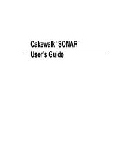
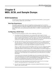
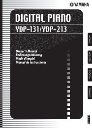
FRONT PANEL/CONNECTORSFRONT PANEL CONTROLS ANDCONNECTORSHere’s a quick guide to the controls and connectorson the MICRO SYNC.1 AUDIO INPUT - ConnectorUse the input cable ( supplied) to connect thissocket to the booth/record or master output onyour mixing desk.2 AUDIO INPUT LEVEL - IndicatorUse this bi-colour red/green LED to maintain theideal input level. See ‘ Setting the correct InputLevel ’on page 5.3 POWER IN - ConnectorConnect the output plug of the AC adaptorsupplied with the MICRO SYNC to this socket.4 BPM - DisplayThe four digit BPM reading of the audio signal willbe displayed here.5 RUN/PAUSE - ButtonPress this button to run or pause the connectedMIDI sequencer. (Also sets the BPM range)6 TAP (RESET/STOP) - ButtonTap this button to <strong>manual</strong>ly enter a BPM. Pressand hold the button to stop the MIDI clock andreset the BPM display.7 SYNCHRONISATION - DisplayThis 3-way indicator shows any synchronisationadjustments.8 NUDGE - 4 ButtonsUse this 4-way keypad to <strong>manual</strong>ly edit the BPMreading or adjust the audio/MIDI sync point - seepage 8. (Also used for parameter editing)9 MIDI CLOCK - DisplayThis 8 indicator display ‘rotates’ at the BPM ratewhen the MICRO SYNC’s MIDI clock is running.10 MIDI OUT - ConnectorUse a suitable MIDI cable to connect this socket tothe MIDI IN connector on your sequencer.4567891INPUT1384bpmmicro syncPULLPULLOKSYNCBPMUPNUDGEPOWERwww.redsound.com<strong>Red</strong> <strong>Sound</strong>the colour of music+/2-/TAPRESET/STOPPUSHPUSHBPMdownBEAT 1MIDI CLOCKMIDI OUT103PAGE2
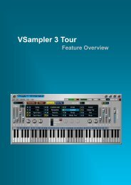
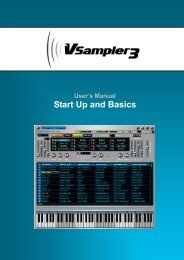
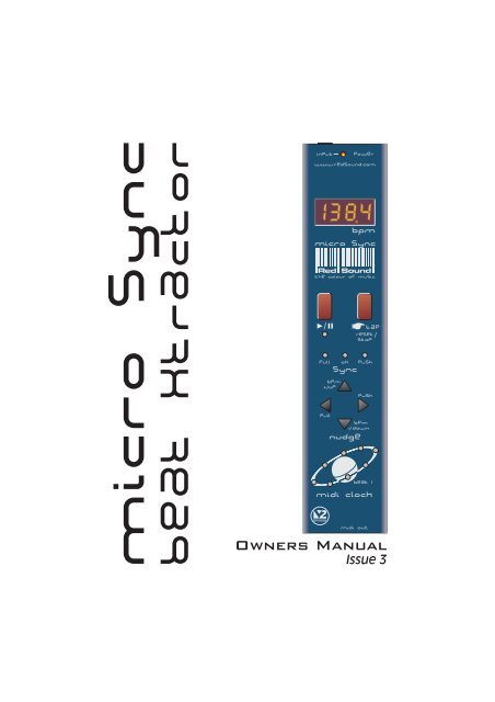
Beat XtractorPULLBPM+/UPPUSHBPM-/DOWNMOUNTING/CONNECTIONSMOUNTING THE MICRO SYNCYou can choose one of three mounting optionsincluded with the MICRO SYNC.1. Rubber feet - Stick one in each corner onthe underside panel for free mounting.2. Double sided adhesive pads - Stick oneeither side of the serial number label on theunderside panel. Locate a flat, clean surfaceon your equipment/rig, peel-off film and pressfirmly into place for a permanent mounting.3. Brackets, for use with 19” rack mountholes on mixing desks - The MICRO SYNCcan be conveniently located on either side of amixing desk for a semi-permanent mounting.CONNECTING THEMICRO SYNC TO YOURSYSTEM19” RACK MOUNT HOLERLRECORD/BOOTHORMASTER OUTPUTM6 SCREWINPUT CABLE(SUPPLIED)M6 NUTBRACKETM3 SCREW(LENGTH = 6mm MAX)DJ MIXING DESK PANELRotate the chromebrackets to line-upwith the 19” rackmounting holes onyour mixing desk.TO ACADAPTORWhen you have chosen the bestmounting option for your system setup,connect the MICRO SYNC as follows:1. Using the input cable supplied,connect the 3.5mm plug end to theMICRO SYNC socket marked ‘INPUT’ onthe rear panel.2. Connect the RCA phono plugs of thecable to a suitable line level output onyour mixing desk. (Record, Booth etc.)REDMICRO SYNC/BEAT 1MIDI CLOCKTAP(RESET/STOP)PULL OK PUSHSYNCNUDGE19” RACKHole pitchrange =Min 90mmMax 240mmMIDI OUT3. Connect the output plug of the ACpower adaptor to the MICRO SYNC’spower in socket on the rear panel.MIXING DESK4. Connect the MIDI OUT socket on theSUITABLEMIDI CABLEfront panel of the MICRO SYNC to theAUDIO OUT MIDI INMIDI IN socket of your sequencer, usinga suitable MIDI cable.TO SUB-MIXER: DO NOTCONNECT MIDI AUDIO303/505SIGNAL BACK INTO MAINMIXER AS A FEED-BACKLOOP WILL OCCUR.MIDI SEQUENCER / TONE MODULEPAGE3
OPERATIONEXTERNAL MIDI SEQUENCER SETTINGSBefore the MICRO SYNC can operate correctly your MIDI sequencer must first be set torecognise externalMIDI Clock commands. Please consult the manufacturers operation<strong>manual</strong> to make the necessary settings. Here are some typical examples:ROLAND MC-303/505In System Settings, set the 'SYNCHRONIZATION SETTING' to 'Slave' mode.E-MU Orbit / Planet Phatt etc.In Master Menu, set 'GLOBAL TEMPO' down below 1 BPM to 'External' mode and set the'BEATS MODE to 1, 2 or 3.QUASIMIDI RAVE-O-LUTION 309In the 'EDIT' page press F3 to select 'SYSTEM'. Select page 3 with the 'PAGE' dial. Use the'EDIT VALUE' wheel to set MIDI SYNC to 'EXT'.GETTING STARTED/POWERING UPThe MICRO SYNC has been designed to operate from the main output signal on a mixingdesk or any line level audio source. When connecting to a mixing desk, this signal can usuallybe taken from a secondary parallel master output labelled ‘RECORD’ or ‘BOOTH OUTPUT’. Ifyour mixing desk does not feature this type of output, use two ’Y’ type RCA phono splitterconnectors on the master output terminals so that both the amplification system and MICROSYNC receive the same signal. Alternatively you can connect to any ‘EFFECT SEND’.NOTE 1: When the MICRO SYNC is in use, avoid changing any volume or tone controls onthe mixing desk as this could greatly affect the MICRO SYNC's synchronisation performance.(Example: a ‘Bass’ tone control turned right down would eliminate all the kick drum beatinformation from the track).NOTE 2: A sub-mixer MUST be used to combine the MIDI driven audio and main audiooutput signals - see connection diagram. MIDI driven audio played back into the MICROSYNC’s input from the main mixer will create a feedback loop. This will result in the MICROSYNC following it's own tempo rather than the master audio signal.When power is first applied to the MICRO SYNC the software version fitted to your unit will beshown in the main display.BPMSoftware version = 2.02(i.e. ‘V2’ BPM engine)Afterwards, the four centre bars will light to indicate the BPM engine is currently ‘IDLE’.BPMFour static centre barsindicate ‘IDLE’ condition(no audio beat detected)PAGE4
OPERATIONSETTING THE CORRECT INPUT LEVELThe MICRO SYNC’s input stage will work most effectively when the audio levels within yourmixing desk are set to their nominal settings i.e. Individual channel Gain/level controls set to0dB - Master output fader set to 0dB. The bi-colour ‘INPUT’ indicator at the top of the frontpanel can show four different input level conditions as follows:OFF- No audio signal presentDIM GREEN - Audio signal present - Level too lowBRIGHT GREEN - Audio signal present - Ideal working levelRED- Overloaded signal - Level too highFor satisfactory operation, this indicator should always be BRIGHT GREEN, occasionallyflashing RED. If the indicator shows a different condition, check the channel/master settingson your mixing desk.IMPORTANT NOTE: If the indicator is continuously DIM GREEN, the BPM engine mayoperate erratically. If the indicator is continuously RED the BPM engine may cease to function.If the signal level is continuously too high, a secondary overload warning will be shown on themain display as follows:BPM BPM BPM4 risingcentre barsindicate'input overload'conditionIf the display shows the overload warning at any time, check and adjust back the gain settingson the mixing desk.Play a track containing steady, definable beat information on any connected sound source,route it to the master output on your mixing desk and set the master level fader to it’s normaloperating position. If the MICRO SYNC is connected to the ‘Booth’ outputs on your mixingdesk, turn up the Booth Output level control until the ‘Input’ indicator lights BRIGHT GREEN,occasionally flashing RED. If the MICRO SYNC is connected directly to the master outputs,turn up the Master fader until the Input indicator shows the same condition as above.NOTE: Regularly check and adjust the input level setting to compensate for individual tracklevel variations.BPM DISPLAYThe main display should now show the BPM reading of the master audio signal as in thefollowing example:BPMExample reading = 138.2 BPMPAGE5
OPERATIONAlso, the / indicator and ‘Beat 1’ indicator in the MIDI CLOCK display will flash at thedetected BPM rate to show ‘PAUSE’ mode. The right-hand digit of the BPM display mayfluctuate slightly as the BPM engine constantly analyses and updates the reading in real-time.Any progressive shift in tempo (slowly changing the playback speed using a CD/vinyl deck’spitch control) should be tracked and displayed by the MICRO SYNC.IMPORTANT NOTE: If the BPM engine has picked up on the OFF-BEAT information in thetrack (LEDs flashing on the off-beats) from a prominent Hi-Hat etc., you can use the NUDGEcontrol’s Pull/Push feature to adjust the synchronisation to the on-beat position - see page 8.RUN/PAUSE Button ( / )Select a suitable pattern on your MIDI sequencer (basic percussion parts are best whenstarting out).RUN: To run the MIDI sequencer, press the 'RUN/PAUSE' button once.NOTE: To set the initial alignment of the MIDI sequence and audio track, press this buttonaccurately on the desired beat. Any misalignment error at this stage will be automaticallycorrected during the first few seconds of operation. This feature allows you to choose theexact start point of the MIDI pattern.The RUN/PAUSE indicator will now stay on and the MIDI CLOCK display will 'rotate' insynchronisation with the audio BPM rate to indicate that the MIDI clock output is active. Theselected pattern in your MIDI sequencer should now be playing in synchronisation with theaudio track.PAUSE: To pause the MIDI sequencer at any time, press the 'RUN/PAUSE' button again. TheMIDI CLOCK display will stop rotating and the RUN/PAUSE / Beat 1 indicators will flash toindicate PAUSE mode. The MIDI sequencer's pattern or song will be held at the pauseposition and will only continue from that point when the RUN/PAUSE button is next pressed.RESET: If you want to run the MIDI pattern from the start point again, in pause mode press theTAP button once before pressing the RUN/PAUSE button again. This resets the MIDI patternor song to beat 1/bar1.IMPORTANT NOTE: The MICRO SYNC will continue running the MIDI clock output indefinitelyat the last detected BPM rate if the strong regular beats in the audio track becomeunavailable. This feature allows the connected MIDI sequencer to fill in parts during quitepassages in the audio track without interruption or to continue playing after the track hasfinished.If the strong regular beats in the audio track become unavailable at any time, the 3 remainingdecimal point indicators in the main display will flash continuously as shown:BPM3 flashing decimal points indicate'free-wheeling' conditionPAGE6
OPERATIONThis will occur approximately 3-4 seconds after the last valid BPM reading was taken to warnthat the MICRO SYNC is now 'free-wheeling' and the BPM display is no longer being updatedfrom the audio track. When the strong regular beats in the audio track return the MICROSYNC will automatically detect the BPM information and make any necessary adjustments, atwhich time the flashing decimal point indicators will go out to indicate a 'locked-in' condition.TAPButton(RESET/STOP)This multi-function button allows you to <strong>manual</strong>ly enter a tempo (TAP), reset the MIDI patternto beat1/bar1 (RESET) in pause mode, dis-engage the automatic beat synchronisation or stopthe MIDI device (STOP).TAP: The TAP feature can be used to set the MIDI Clock speed when there is no audio signalpresent or when the beat information becomes unavailable during a quite passage of theaudio track (intro, middle eight etc.).To enter a BPM rate from IDLE (no audio beat detected) use your finger to tap in a tempo onthe TAP button. After 3-4 taps the tempo will be shown on the main BPM display. TheRUN/PAUSE and Beat 1 indicators will flash at the BPM rate to show PAUSE mode.The TAP feature can also be used to override the BPM engine whilst detecting a BPM or 'freewheeling’.Use your finger to tap in the tempo. After 3-4 taps the new tempo will be shown onthe main BPM display and the MIDI clock will immediately change to run at the new rate.NOTE: Subsequent valid beat information detected by the BPM engine may override any<strong>manual</strong> changes made with the TAP function.RESET TO BEAT 1/BAR 1: For details on the RESET function please see previous page.DISENGAGE AUTO- SYNC: The TAP button can also be used to temporarily disengage theMICRO SYNC’s automatic beat tracking whilst in RUN mode. This feature allows the MICROSYNC to ignore sections of erratic, offbeat material present in certain sections of many audiotracks that can cause unnecessary adjustments and temporary disruption to thesynchronisation. The MIDI device can then run- on, uninterrupted at the last detectedsynchronisation setting.In RUN mode only, press the TAP button. The three indicators in the SYNC display (and thedecimal points in the main display) will flash together at the BPM rate to indicate ‘SyncDisengaged’ mode. To reset the automatic tracking back ON, press the TAP button again. Theindicators in the SYNC and MAIN displays will revert to their normal operation.STOP: The STOP function is used to stop the MIDI Clock and clear BPM readings from theMICRO SYNC. Press and hold down the TAP(RESET/STOP) button for approximately 1second. The BPM reading in the main display will be replaced by four centre bars and theMIDI CLOCK, RUN/PAUSE indicators will go out (and the connected MIDI device will stop).PAGE7
OPERATIONSYNC IndicatorThis 3-way indicator shows beat synchronisation adjustments between the audio track andthe MIDI sequencer’s beat position. The MICRO SYNC constantly analyses the accuracy ofthe relative beat positions and will either 'PULL' or 'PUSH' the MIDI clock output to maintainthis synchronisation.When the audio and MIDI are synchronised the green 'OK' indicator will light.PULL OK PUSHSYNCIf the MIDI clock is ahead of the audio, the red 'PULL' indicator will light.PULL OK PUSHSYNCIf the MIDI clock is behind the audio, the red 'PUSH' indicator will light.PULL OK PUSHSYNCNUDGE ControlThe 4-button NUDGE control lets you make fine adjustments to the BPM rate and audio/MIDIsynchronisation point.BPM Adjustments (using BPM +/Up and BPM -/Down buttons): During normal operation,the BPM engine will automatically detect and adjust itself to the correct BPM value. However,if the MICRO SYNC’s software is ‘free-wheeling’ or you wish to adjust a ‘tapped in’ tempo, youcan use the North /South positions of the NUDGE control to increase or decrease the BPMvalue in 0.1 BPM steps.To increase the BPM reading by 0.1 BPM, press the top button once, as in the followingexample:BPM+/UPPULLPUSHBPM-/DOWNNUDGETo decrease the BPM reading, press the lower button once ( BPM -/DOWN). Press and hold downeither button to scroll through the BPM values. Further ‘valid’ beat information detected by theBPM engine will override any <strong>manual</strong> changes made with these buttons.Setting the default BPM - The BPM +/Up, -/Down buttons can be used to quickly enter adefault BPM value. When the BPM engine is ‘Idle’ (four centre bars on), simply press eitherbutton to set the default reading of 120 BPM . The MICRO SYNC is now ready to run theconnected MIDI sequencer at 120 BPM. You can adjust this setting with the TAP or NUDGE (-/BPM or +/BPM) buttons.PAGE8
OPERATIONSYNC Adjustments (using PULL and PUSH buttons): Under normal circumstances theBPM engine will automatically detect and adjust the audio/MIDI trigger point to either the onbeator off-beat position depending on whichever is more prominent in the audio track. Youcan use the PUSH/PULL feature to make fine adjustments to the synchronisation (if the MIDIsequencer sounds slightly ahead or behind the beat of the audio) or complete ½ beat steps (ifthe BPM engine has locked to the off-beat when you require synchronisation to be on the beator vic-versa).To check the current trigger synchronisation setting, press either the ‘PULL’ or PUSH’ buttononce. The main BPM display and SYNC indicators will now show the current setting, as in thefollowing example:BPMExample: Trigger point =‘Synchronised’Flashing ‘OK’ indicatorPULLOKSYNCAfter 4 seconds the BPM display and SYNC indicators will revert to their normal operation.To adjust the trigger synchronisation setting, again press one of the buttons marked ‘PULL’ or‘PUSH’ and then, during the 4 second display period, press either button again to change thesetting. Each half beat measure has 12 interim settings which allow very fine adjustments tobe made to the synchronisation.PULL THE SYNCHRONISATION: To ‘Pull’ the MIDI clock backwards, press the left button(PULL) during the 4 second display period.BPM+/UPPUSHPULLPUSHBPM-/DOWNNUDGEThe display reading will change for each press as follows:LGH / BARPOSLGH/BARPOSLGH/BARPOSEtc. to -11BPMBPMBPMPULL OK PUSH PULL OK PUSH PULL OK PUSHAfter the ‘-11’ setting, the synchronisation will be pulled back exactly ½ beat, as indicated bythe following display:PAGE9
OPERATIONLGH/BARPOSLGH/BARPOSDisplay alternatesbetweenBPMBPMPULLOKPUSHPULLOKPUSHFurther fine adjustments can be made beyond the ‘PULL ½ beat’ point (display reads from‘-13’ down to ‘-23’) until the synchronisation is pulled back by one complete beat (maximumPULL adjustment). For this setting the display will show the following:LGH / BAR POS LGH / BAR POSDisplay alternatesbetweenBPMBPMPULLOKPUSHPULLOKPUSHNOTE: You can adjust the PULL/PUSH setting in complete ½ beat steps by pressing andholding down either button for 1 second.PUSH THE SYNCHRONISATION: To ‘Push’ the MIDI clock forwards, press the right button(PUSH) during the 4 second display period.BPM+/UPPULLPUSHBPM-/DOWNNUDGEThe display reading will change for each press as follows:LGH / BAR POSLGH/BAR POSLGH/BARPOSBPMBPMBPMEtc. to +11PULL OK PUSH PULL OK PUSH PULL OK PUSHAfter the ‘+11’ setting, the synchronisation will be pushed forwards exactly ½ beat, as indicatedby the following display:LGH/BARPOSDisplay alternatesbetweenLGH/BARPOSBPMBPMPULLOKPUSHPULLOKPUSHPAGE10
OPERATIONFurther fine adjustments can be made beyond the ‘PUSH ½ beat’ point (display reads from‘+13’ up to ‘+23’) until the synchronisation is pushed forwards by one complete beat(maximum PUSH adjustment). For this setting the display will show the following:LGH / BAR POS LGH / BAR POSDisplay alternatesbetweenBPMBPMPULLOKPUSHPULLOKPUSHBPM RANGEThis is where you set the working range of the MICRO SYNC’s BPM engine. There are threeoperating bands, each specifically designed to complement different styles of music from slowballads to the fastest ‘Speed Garage’. This setting can only be accessed when the BPMengine is in the ‘Idle’ condition (four centre bars). To check the setting in idle mode, pressthe / button once, the display will alternate between:LGH/BARPOSLGH/BARPOS‘r’ = rangeDisplay alternatesbetweenBPMBPMDefault setting = MED(90-180 BPM)SETTING RANGE = LOW (60 to 120BPM), MED (90 to 180BPM), HIGH (115 to 230BPM)To change the BPM range, use the NUDGE control ‘BPM +/UP’ or ‘BPM -/DOWN’ buttons, asin the following example:BPM+/UPPULLPUSHBPM-/DOWNNew setting = HI (115-230 BPM)LGH/BARPOSNUDGELGH/BARPOSDisplay alternatesbetweenBPMTo exit ‘BPM edit’ mode, simply press thereturn to ‘Idle’ mode./BPMbutton again. The MICRO SYNC will nowNOTE 1: BPM’s outside of the selected range limit cannot be analysed. Always check thegeneral tempo of the music you are playing falls well within the selected BPM range. For mostapplications we recommend the MID BPM range of 90-180BPM.NOTE 2: This setting is not memorised. Each time the MICRO SYNC’s power is turned on, thedefault setting (90-180 BPM) will be restored.PAGE11
HINTS&TIPS / SPECIFICATIONHINTS & TIPSTempo Changes:1. Always make slow changes when adjusting the sound source pitch control. This will allowthe MIDI clock to remain in synchronisation during tempo changes.2. Never make tempo changes during quite passages (when beat information is unavailable)as the MICRO SYNC will lose synchronisation.Synchronisation:1. Use the NUDGE feature to <strong>manual</strong>ly adjust any synchronisation errors during quitepassages (when beat information is unavailable).2. Get to know a track before a performance to identify passages which upset thesynchronisation. Then disengage the auto SYNC prior to breaks which contain the erratic beatinformation.SPECIFICATIONBPM RangeLock-in timeAccuracyInput LevelBPMSyncInputMIDI clockInput cableMounting kitBPM Engine3 x ranges: Low = 60 to 120 BPM, Med = 90 to 180 BPM,High = 115 to 230 BPMTypically 2-4sec's(from introduction of readable beat information)0.1 BPMNominal line level (1V peak)Displays1 x 4 character 7 Segment LED3 x LED1 x Bi-colour green/red LED8 x red LEDAccessories (included)1M (3.5mm mini-jack to RCA phono plugs),2 x chrome brackets /2xM6screws /2xM6nuts/2xM3screws,2 x double-sided adhesive pads,4 x rubber feetMIDI ImplementationSystem real time / Clock commands = transmittedPower Supply9vDC, 250mA (RED PSU - TYPE A)Dimensions/Weight42(W)x195(D)x22(H)mm, Less than 0.5 Kg* Specification and /or appearance subject to change without prior notice due to productimprovement.Patent PendingPAGE12
FEDERAL COMMUNICATIONS COMMISSIONRADIO FREQUENCY INTERFERENCE STATEMENTFor the USAThis equipment has been tested and found to comply with the limits listed for a Class B digitaldevice, pursuant to Part 15 of the FCC Rules. These limits are designed to provide reasonableprotection against harmful interference in a residential installation. This equipment generates,uses, and can radiate radio frequency energy and, if not installed and used in accordance withthe instructions, may cause harmful interference to radio communications. However, there isno guarantee that interference will not occur in a particular installation. If this equipment doescause harmful interference to radio or television reception, which can be determined by turningthe equipment off and on, the user is encouraged to try to correct the interference by one ormore of the following measures:- Reorient or relocate the receiving antenna.- Increase the separation between the equipment and receiver.- Connect the equipment into an outlet on a circuit different from that to which the receiver isconnected.- Consult the dealer or an experienced radio/TV technician for help.Unauthorized changes or modifications to this system can void the users authority to operatethis equipment.This equipment requires shielded interface cables in order to meet FCC class B limit.For EuropeThis product complies with the requirements of European Directive 89/336/EECCLASS BNOTICEFor CanadaThis digital apparatus does not exceed the Class B limits for radio noise emissions set out inthe Radio Interference Regulations of the Canadian Department of Communications.CLASSE BAVISCet appareil numerique ne depasse pas les limites de la Classe B au niveau des emissions debruits radioelectriques fixes dans le Reglement des signaux parasites par le ministereCanadien des Communications.Copyright / Software Copyright / Design Right RED <strong>Sound</strong> <strong>Systems</strong> Ltd 2001Printed in England
Bourne House, Cores End Road,Bourne End, Bucks. SL8 5AR. EnglandPhone : +44 (0)1628 819191Fax : +44 (0)1628 819111