Infader manual.pdf - Red Sound Systems
Infader manual.pdf - Red Sound Systems
Infader manual.pdf - Red Sound Systems

Create successful ePaper yourself
Turn your PDF publications into a flip-book with our unique Google optimized e-Paper software.
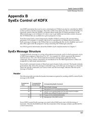
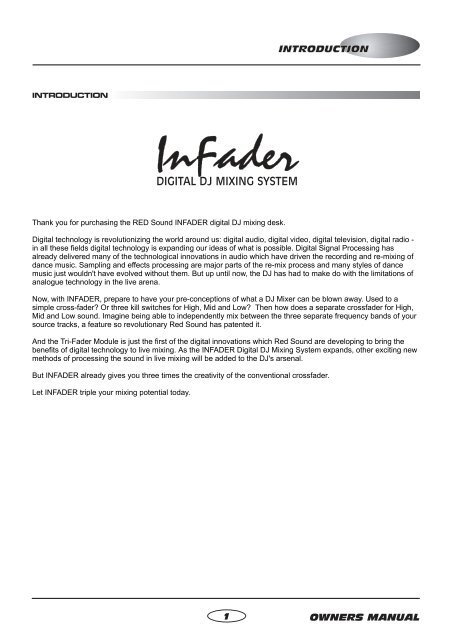
INTRODUCTIONINTRODUCTIONInFaderDIGITAL DJ MIXING SYSTEMThank you for purchasing the RED <strong>Sound</strong> INFADER digital DJ mixing desk.Digital technology is revolutionizing the world around us: digital audio, digital video, digital television, digital radio -in all these fields digital technology is expanding our ideas of what is possible. Digital Signal Processing hasalready delivered many of the technological innovations in audio which have driven the recording and re-mixing ofdance music. Sampling and effects processing are major parts of the re-mix process and many styles of dancemusic just wouldn't have evolved without them. But up until now, the DJ has had to make do with the limitations ofanalogue technology in the live arena.Now, with INFADER, prepare to have your pre-conceptions of what a DJ Mixer can be blown away. Used to asimple cross-fader? Or three kill switches for High, Mid and Low? Then how does a separate crossfader for High,Mid and Low sound. Imagine being able to independently mix between the three separate frequency bands of yoursource tracks, a feature so revolutionary <strong>Red</strong> <strong>Sound</strong> has patented it.And the Tri-Fader Module is just the first of the digital innovations which <strong>Red</strong> <strong>Sound</strong> are developing to bring thebenefits of digital technology to live mixing. As the INFADER Digital DJ Mixing System expands, other exciting newmethods of processing the sound in live mixing will be added to the DJ's arsenal.But INFADER already gives you three times the creativity of the conventional crossfader.Let INFADER triple your mixing potential today.1OWNERS MANUAL
TOP PANELMIC INSERTPOWERREDwww.redsound.comCHANNEL 1 CHANNEL 2 OUTPUTSFX LOOP (AUX)71CHANNEL 1PRE-TRIMMIC - LINEMINMAXMIC LEVELLINEPUSH-12dB-12dBEQ - HIGHEQ-LOW+12dB+12dBMINMAXTRIMCLIPMINLEVELMAXBOOTHOUTPUTLEVEL (VU)+5+3+10-1-3-5-7-10-15MINMAXLEVELMASTERInFaderDIGITAL DJ MIXING SYSTEMMINMAXLEVELMASTERCH1CH2PREPRECH1CH2POSTPOSTCLIPSELECTSENDMINMAXTRIMCLIPMINLEVELMASTERCH1MAXCH2SELECTRETURN/AUXFX-AUXCHANNEL 2PRE-TRIM425CH 1-85dB+4dBHIGH-85dB+4dBMID-85dBONLOCKOFFLOW+2dBFX109876543210CD/LINEPHONO+5+3+10-1-3-5-7-10-15CD/LINEPHONO9876543210-85dB+4dBHIGH10 -85dB +4dB-85dBMIDLOW+2dBCH 236ONCH1 LEVELCH2 LEVELX-FADERCURVEHIGHHIGHREDDIGITAL DJ MIXING SYSTEMTRI-FADER MODULE8MIDMID910REVERSELOW(MASTER)LOWREVERSE11MASTERSPLITX1X3X-FADER MODETRI - FADERS(Patent Pending)NORMALCENTRE OFFX-FADER STATUSSPLIT CUE EQ CUT LEVEL SELECT PHONESInFader - Digital DJ Mixing Desk2
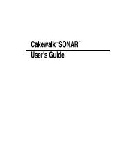
TOP PANEL FEATURESFRONT PANEL FEATURES1. MIC/LINE INPUT: This section features [LEVEL], [EQ-HIGH] and [EQ-LOW] controls for the selectablemicrophone/line level input stage. The [MIC/LINE] push-button switch selects the input type. The combi-XLRconnector accepts XLR connectors for microphone use and ¼ Jack plugs for mono line level devices (CD/tapeplayers, drum machines, synthesizers etc.)2. CHANNEL 1 INPUT: This section features [TRIM], [INPUT SELECT], [LEVEL], [EQ-LOW], [EQ-MID] and [EQ-HIGH] controls for the channel 1 input stage. The [PRE-TRIM] control for this channel is situated on the left-handside panel. The bi-colour [CLIP] indicator shows the pre-A-to-D convertor level status. The 10-way indicator showschannel level with 2 second peak-hold feature. This channel can be used with any CD/line or Phono level inputdevice.3. CHANNEL 2 INPUT: This section features [TRIM], [INPUT SELECT], [LEVEL], [EQ-LOW], [EQ-MID] and [EQ-HIGH] controls for the channel 2 input stage. The [PRE-TRIM] control for this channel is situated on the right-handside panel. The bi-colour [CLIP] indicator shows the pre-A-to-D convertor level status. The 10-way indicator showschannel level with 2 second peak-hold feature. This channel can be used with any CD/line or Phono level inputdevice.4. FX SEND/RETURN - AUXILIARY INPUT: This section features [SEND LEVEL], [SEND SELECT], [RETURN/AUX LEVEL] and [RETURN/AUX SELECT] controls for the effects loop/auxiliary input stage. The bi-colour [CLIP]indicator shows the pre-A/D convertor level status for the effects return/auxiliary input. The RETURN/AUX channelcan be used with any CD/line level input device.5.6.FX ON/OFF SWITCH: This 3-way ‘paddle’ switch controls the effect send/return loop.X- FADER CURVE: This control allows you to adjust the characteristics of the crossfader curve.7. MASTER/BOOTH OUTPUT: This section features the [MASTER LEVEL] and [BOOTH LEVEL] controls. The10-way VU indicator shows the MASTER output level.8.TRI-FADERS: This section features the [LOW/MASTER], [MID] and [HIGH] fader controls.9. REVERSE: The two [REVERSE] buttons are connected in parallel. When either button is pressed, the currentfader position(s) will be automatically reversed.10. X- FADER MODE: This 2-way switch selects between [MASTERx1] mode (single crossfader operation) and[SPLITx3] mode (3-way crossfading).11. X- FADER STATUS: This 2-way switch selects between [NORMAL] status (fader in centre position = CH1,CH2 sound ON) and [CENTRE OFF] status (fader in centre position = CH1, CH2 sound OFF).3OWNERS MANUAL
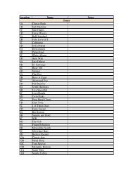
REAR PANELFX LOOP (AUX)RETURN SEND(AUX IN)OUTPUTSMASTERBOOTHSIGNALGNDCHANNEL 2PHONOCD/LINESIGNALGNDCHANNEL 1PHONOCD/LINEONPOWER16VDCMICINSERTLLLLRRRROFF-+RIGHT MASTER OUTPUT (BALANCED) LEFTInFaderDIGITAL DJ MIXING SYSTEM2 COLDCAUTION: DO NOT OPEN CASEREFER TO QUALIFIED SERVICE PERSONNELNO USER SERVICEABLE PARTS INSIDEMADE IN ENGLAND Patent PendingRED <strong>Sound</strong> <strong>Systems</strong> Ltd3 HOT1 GND1 2 3 4 567 81. FX LOOP [AUX] - RCA Phono ConnectorsUse these sockets to connect any external effects processor to INFADER. Alternatively, you can use the[RETURN/AUX IN] sockets to connect an additional stereo CD/line level sound source to INFADER for multichanneloperation whilst using the [SEND] connectors as a RECORD out. INFADER is shipped with shorting barsfitted between the send and return sockets to avoid ‘no output’ conditions when the front panel ‘FX’ switch is set toon.2. BALANCED MASTER OUTPUTS - XLR ConnectorsUse these sockets to connect INFADER to amplification systems supporting balanced XLR input.3. OUTPUTS - RCA Phono ConnectorsUse the sockets marked [MASTER] to connect INFADER to amplification systems supporting unbalanced RCAinput. Use the sockets marked [BOOTH] to connect INFADER to the monitor amplification system.4. CHANNEL 2 - RCA Phono Connectors/Earth TerminalUse the sockets marked [PHONO] and [SIGNAL GND] to connect the analog turntable to channel 2. Use thesockets marked [CD/LINE] to connect the CD or line level audio player to channel 2.5. CHANNEL 1 - RCA Phono Connectors/Earth TerminalUse the sockets marked [PHONO] and [SIGNAL GND] to connect the analog turntable to channel 1. Use thesockets marked [CD/LINE] to connect the CD or line level audio player to channel 1.6. POWER - SwitchThis turns the power on and off.7. DC POWER IN - ConnectorIMPORTANT: Only use the 16vDC 750 mA PSU supplied with INFADER to power the unit.8. MIC INSERT - ¼ Jack ConnectorUse this socket to send/return the MIC/LINE channel signal to an external sound processor.InFader - Digital DJ Mixing Desk4
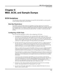
FREQUENCY1/4SET (SPEED)SET(CLEAR BPM)TAP1/3LEVEL1/4PULLRESONANCE1/3BPM+/UP1/2NUDGE2/3 3/4BEATSENV MOD11/1ACTIVATEFILTER/LFOREPEAT1/2 2/3 3/4BEATSACTIVATEDELAYPATTPUSHBPM-/DOWNOff1/41/1Max2/1USERSPEED2/121/3SPEED(MASTER)OUT/ININPUTLEVELPATTERN SETSet Pattern LengthSet Quantize131/2FEDERATIONBPM FX - DJ2BPMPULL OK PUSHSYNCHRONISATIONFX MIXERUSER BEATS4LGH / BAR2/33BEATSPOS53/44UTILITYLIVE(REC)61/1SHAPETripletOff1/41/472/12- WaySPSMinMaxDEPTH1/31/3Full1/2Lo-Mid Mid-Hi2-WAY SPLIT1/2ACTIVATECUTTER8Lo-HiACTIVATEPANNINGUSER2/3 3/4BEATS2/3 3/4BEATSWholeSPEED1/11/12/1PROG.BAR LOOPSPEED2/1MinMaxMONITORUSERUSERSETSETMASTERON/OFFTMFREQUENCY1/4SET (SPEED)SET(CLEAR BPM)TAPRESONANCE1/3LEVEL1/4PULL1/3BPM+/UP1/2NUDGE2/3 3/4BEATSENV MOD11/1ACTIVATEFILTER/LFOREPEAT1/2 2/3 3/4BEATSACTIVATEDELAYPATTPUSHBPM-/DOWNOff1/41/1Max2/1USERSPEED2/121/3SPEED(MASTER)OUT/ININPUTLEVELPATTERN SETSet Pattern LengthSet Quantize131/2FEDERATIONBPM FX - DJ2BPMPULL OK PUSHSYNCHRONISATIONFX MIXERUSER BEATS4LGH / BAR2/33BEATSPOS53/44UTILITYLIVE(REC)61/1SHAPETripletOff1/41/472/12- WaySPSMinMaxDEPTH1/31/3Full1/2Lo-Mid Mid-Hi2-WAY SPLIT1/2ACTIVATECUTTER82/3 3/4BEATSLo-Hi2/3 3/4BEATSSPEED1/1ACTIVATEPANNINGUSERWhole1/12/1PROG.BAR LOOPSPEED2/1MinMaxMONITORUSERUSERSETSETMASTERON/OFFTMINPUT CONNECTIONSRED FEDERATION BPM FXwww.redsound.comREDCD / TAPE 1CD / TAPE 2LINE LEVELAUDIO DEVICEor...or...CD / TAPE 3Remove SHORTING BARSbefore connecting FX deviceMICROPHONE[balanced only]RLRLRLRLFX LOOP (AUX)OUTPUTSCHANNEL 2CHANNEL 1POWERMICRETURN(AUX IN)SENDMASTERBOOTHSIGNALGNDPHONOCD/LINESIGNALGNDPHONOCD/LINEON16VDCINSERTLLLLLRRRRIGHT MASTER OUTPUT (BALANCED) LEFT2 COLDInFaderRDIGITAL DJ MIXING SYSTEMR- +OFFCAUTION: DO NOT OPEN CASEREFER TO QUALIFIED SERVICE PERSONNELNO USER SERVICEABLE PARTS INSIDEMADE IN ENGLAND Patent PendingRED <strong>Sound</strong> <strong>Systems</strong> Ltd3 HOT1 GNDSendReturnGroundPin assignmentLRLRTOAC WALLSOCKETRED PSUwww.redsound.comOUT INREDANALOG TURNTABLE 1 ANALOG TURNTABLE 2RED FEDERATION BPM FX(OR OTHER EFFECTS DEVICE)5 OWNERS MANUAL
OUTPUT CONNECTIONSPOWER AMPLIFIER(UN-BALANCEDRCA INPUT)HEADPHONESRLFX LOOP (AUX)OUTPUTSCHANNEL 2CHANNEL 1POWERMICRETURN(AUX IN)SENDMASTERBOOTHSIGNALGNDPHONOCD/LINESIGNALGNDPHONOCD/LINEON16VDCINSERTCONNECT TOFRONT PANELSOCKETLLLL- +OFFRRRRRIGHT MASTER OUTPUT (BALANCED) LEFT2 COLDInFaderDIGITAL DJ MIXING SYSTEMCAUTION: DO NOT OPEN CASEREFER TO QUALIFIED SERVICE PERSONNELNO USER SERVICEABLE PARTS INSIDEMADE IN ENGLAND Patent PendingRED <strong>Sound</strong> <strong>Systems</strong> Ltd3 HOT1 GND2 COLD3 HOT1 GNDPin assignmentLRPOWER AMPLIFIER(BALANCED XLR INPUT)POWER AMPLIFIERFOR BOOTH MONITORInFader - Digital DJ Mixing Desk6
FRONT PANELSPLIT CUE EQ CUT LEVEL SELECT PHONESOffCUEMASTERCH1CH2High CutLow CutMinMaxInFaderDIGITAL DJ MIXING SYSTEMREDwww.redsound.com1 2 34 5The front panel contains the following monitor controls:1. SPLIT CUE - RotaryThis control allows you to monitor channel 1, channel 2 or a mix of both when [SELECT] is set to CUE.2. EQ CUT - RotaryThis control can be used to change the CUE monitor EQ. To the left, high frequencies are cut and to the right, lowfrequencies are cut.3. LEVEL - RotaryThis control sets the audio level to the connected headphones.4. SELECT - PushbuttonThis switch allows you to select MASTER or CUE monitoring.5. HEADPHONE OUT - Jack connectorConnect the ¼ jack plug from your headphones to this connector.GETTING STARTEDBefore use, please observe the following guidelines:CONNECTIONS: Before making any connections, make sure that the power on all your equipment is turned OFF.Connect the power supply (included) to the ‘power in’ socket on the rear panel of INFADER and plug it into asuitable AC outlet. Connect the audio cables for a typical system setup as shown on pages 5/6.TURNING ON THE POWER: Make sure all connections have been made correctly and the volume controls onINFADER and the amplifier system are turned completely down. Press IN the rear panel power switch onINFADER. Turn ON the power to the connected CD/analog players and amplifier system.POWER ON INDICATION: When INFADER is powered up the [FX ON/OFF] indicator flashes to indicate thatpower is switched on. If this does not happen, check the power supply is of the correct type and the unit is switchedon and correctly connected.INFADER is now ready for use.7 OWNERS MANUAL
OPERATIONMIC / LINE INPUTMIC - LINEPUSHMINMAXMIC LEVEL-12dB+12dBEQ - HIGH-12dB+12dBEQ-LOWLINEThis section of INFADER features controls and connectors for the DJ microphone. The circuitry is totally analogand is fed directly to the master output buss (also analog). The combination XLR/Jack connector allows you to usethis input as a 4th line-level input, ideal for introducing a further CD/tape player or other sound source such as MIDIsynthesizer/sequencer.COMBI XLR CONNECTORThis connector accepts the standard XLR plug fitted to BALANCED microphone cables. Before attempting toconnect the microphone, first ensure the [LEVEL] control is set to minimum and the [MIC/LINE] switch is set to the[MIC] position (UP). Align the three pins on the plug with those on the socket and then push home fully until theretaining latch clicks into place. To disconnect the microphone, first press down the retaining tab labelled [PUSH]and then gently pull out the XLR microphone plug.The centre area of this connector also accepts a standard ¼” jack plug for connecting line-level devices. Only monosignals can be routed through this section. If a stereo 1/4” jack plug is inserted, the left/right channels will besummed. Before attempting to connect the line-level device, first ensure the [LEVEL] control is set to minimum andthe [MIC/LINE] switch is set to the [LINE] position (DOWN). Push in the jack plug until it snaps into place. There isno locking facility for this type of connector.LEVEL CONTROLThis control sets the input level for the microphone or line-level device. At the fully anti-clockwise position there willbe no sound. As the control is moved in a clockwise direction the level will be gradually increased until, at the fullyclockwise position, the level will be at its maximum.CARE!: This signal is routed to the master buss POST [MASTER] level control - e.g. the output level of themicrophone or line-level device will be un-affected by the [MASTER] level control.EQ - LOW CONTROLThis control adjusts the bass equalisation of the microphone/line-level sound. At the 12 o’clock, centre clickposition the low EQ will be flat (no cut or boost). As the control is moved anti-clockwise the low frequencies will beprogressively cut until, at the fully anti-clockwise position the maximum low frequency cut will be applied (-12dB).As the control is moved clockwise from the centre position the low frequencies will be progressively boosted until,at the fully clockwise position the maximum low frequency boost will be applied (+12dB@100Hz).EQ - HIGH CONTROLThis control adjusts the treble equalisation of the microphone or line-level sound. At the 12 o’clock, centre clickposition the high EQ will be flat (no cut or boost). As the control is moved anti-clockwise the high frequencies will beprogressively cut until, at the fully anti-clockwise position the maximum high frequency cut will be applied (-12dB).As the control is moved clockwise from the centre position the high frequencies will be progressively boosted until,at the fully clockwise position the maximum high frequency boost will be applied (+12dB@10kHz).InFader - Digital DJ Mixing Desk8
OPERATIONMIC/LINE SWITCHThis push button switch selects the input level sensitivity. When set to the [MIC] position (UP), the XLR part of theinput connector will be active. When set to the [LINE] position (DOWN), the 1/4” Jack part of the input connectorwill be active.MIC INSERT CONNECTOR (REAR PANEL)This 1/4” jack rear panel connector can be used to route the microphone or line-level signal through an externaleffects processor. Using a suitable cable (see page 5 for pin allocation), connect this socket to the in/outs of theeffects device to add reverb/echo or more extreme effects (RED - FEDERATION or XS-FX) to the sound.INPUT CHANNELS 1&2CHANNEL 1PRE-TRIMMINMAXTRIMCLIPInFaderDIGITAL DJ MIXING SYSTEMCLIPMINMAXTRIMCHANNEL 2PRE-TRIMCH 1-85dB+4dBHIGH-85dB+4dBMID-85dB+2dBLOW109876543210CD/LINEPHONO+5+3+10-1-3-5-7-10-15CD/LINEPHONO-85dB+4dBHIGH10 -85dB +4dBMID9876-85dB+2dB5LOW43210CH 2CH1 LEVELCH2 LEVELThis section of INFADER features all the main controls for input channels 1 and 2, most of which come under thecontrol of the digital signal processor (DSP). The EQ sections in both channels are totally created within the DSPwhich enables INFADER to deliver an amazing -85dB of cut whilst, for professional considerations limiting theboost to just +2/4dB. The level faders are also digitally controlled which assures extra long-life for these hardworkingcomponents.INPUT SELECTOR SWITCHESThese 2-way toggle switches select the connected playback device for each channel. In the left-hand position the[CD/LINE] input will be selected. In the right-hand position the [PHONO] analog input will be selected.TRIM CONTROLSThese controls adjust the gain of the input signal. At the 12 o’clock position the gain will be 0dB. As the control ismoved anti-clockwise the gain will be progressively reduced until, at the fully anti-clockwise position the signal willbe at infinity ( ) or off. As the control is moved clockwise from the centre position the gain will be progressivelyincreased until, at the fully clockwise position the maximum gain setting will be applied (+6dB).9 OWNERS MANUAL
OPERATIONCLIP INDICATORS - The bi-colour [CLIP] indicators are used to detect overload conditions in the gain sectionbefore the A/D convertors. When a good signal level is detected, the indicator will light GREEN. When the signallevel becomes too high for the A/D convertor the indicator will change colour to RED and the audio sound willbecome distorted. If this occurs, back-off the [TRIM] control until a GREEN indication (with occasional RED flashes)is shown.PRE-TRIM CONTROLSThese controls are situated on the side panels (channel 1 on LEFT side panel / channel 2 on RIGHT side panel).They can be used to attenuate the input signal level prior to the main [TRIM] control to avoid overload conditions.These controls are factory set to maximum gain (fully clockwise) for professional use. When using high outputplayback devices it may be necessary to back-off the [PRE-TRIM] gain to stop the input channel from overloading.To change the [PRE-TRIM] setting, use a small flat-bladed screwdriver to adjust the potentiometers, as shownbelow:To decrease the PRE-TRIMgain, turn the screwdriveranti-clockwise.To increase the PRE-TRIMgain, turn the screwdriverclockwise.CHANNEL VOLUME FADERSThese 60mm travel faders are digitally controlled by the DSP and are used to adjust the volume of CH1 and CH2.PEAK LEVEL METERThese indicators show the signal level pre-channel faders and cover a range of -15dB to +5dB. The peak holdfeature shows peak level indications for approximately 2 seconds. The indicators from -15 to 0dB are colouredgreen. Indicators +1dB and +3dB are amber whilst the +5dB indicator is coloured red.HIGH EQThese controls adjust the high tone characteristics of the CH1 / CH2 inputs. At the 12 o’clock, centre click positionthe high EQ will be flat (no cut or boost). As the control is moved anti-clockwise the high frequencies will beprogressively cut until, at the fully anti-clockwise position the maximum high frequency cut will be applied (-85dB).As the control is moved clockwise from the centre position the high frequencies will be progressively boosted until,at the fully clockwise position, the maximum high frequency boost will be applied (+4dB@10kHz).MID EQThese controls adjust the mid tone characteristics of the CH1 / CH2 inputs. At the 12 o’clock, centre click positionthe mid EQ will be flat (no cut or boost). As the control is moved anti-clockwise the mid frequencies will beprogressively cut until, at the fully anti-clockwise position the maximum mid frequency cut will be applied (-85dB).As the control is moved clockwise from the centre position the mid frequencies will be progressively boosted until,at the fully clockwise position, the maximum mid frequency boost will be applied (+4dB@1kHz).LOW EQThese controls adjust the low tone characteristics of the CH1 / CH2 inputs. At the 12 o’clock, centre click positionthe low EQ will be flat (no cut or boost). As the control is moved anti-clockwise the low frequencies will beprogressively cut until, at the fully anti-clockwise position the maximum low frequency cut will be applied (-85dB).As the control is moved clockwise from the centre position the low frequencies will be progressively boosted until,at the fully clockwise position, the maximum low frequency boost will be applied (+2dB@100Hz).InFader - Digital DJ Mixing Desk10
OPERATIONFX SEND & RETURN - AUXMINCH1PRECH1POSTLEVELMASTERSELECTSENDMAXCH2PRECH2POSTCLIPMINLEVELMASTERCH1MAXCH2SELECTRETURN/AUXFX-AUXThis section of INFADER features controls for the effects send/return loop, which can also be used as an auxiliaryinput/record output. The routing switches are controlled by the DSP for comprehensive send and return patching.For example, you can take the CH1 input signal (before or after the crossfaders) and route it through an externaleffects device before bringing it back via CH1, CH2 or Master buss. If effects are not required you can connect aline-level playback device to the return side for expanded input channel capability whilst recording a performancefrom the send output. When there are NO devices connected to these terminals we recommend that the suppliedshorting bars are fitted to avoid ‘no output’ conditions if the FX switch is accidentally set to ON.SEND - LEVELThis control sets the output level to the connected effects unit. At the fully anti-clockwise position there will be nooutput signal. As the control is moved in a clockwise direction the output level will be gradually increased until, atthe fully clockwise position, the output level will be at its maximum. Use the input level indicator on your effects unitto monitor and set the correct input level.NOTE: the [FX] switch must be turned ON to output the signal - see next page for further details).SEND - SELECTThis control selects the signal source that will be sent to the external effects unit. There are five ‘tap-off’ points tochoose from, as detailed below:1. CHANNEL 1 POST - Only the CH1 signal will be transmitted, post-crossfaders (AFTER any crossfader filtering).2. CHANNEL 1 PRE - Only the CH1 signal will be transmitted, pre-crossfaders (BEFORE any crossfader filtering).3. MASTER - The master output signal will be transmitted (only MASTER RETURN can be selected for this setting).4. CHANNEL 2 PRE - Only the CH2 signal will be transmitted, pre-crossfaders (BEFORE any crossfader filtering).5. CHANNEL 2 POST - Only the CH2 signal will be transmitted, post-crossfaders (AFTER any crossfader filtering).RETURN / AUX - LEVELThis control sets the amount of signal coming back from the connected effects unit. At the fully anti-clockwiseposition there will be no sound. As the control is moved in a clockwise direction the input level will be graduallyincreased until, at the fully clockwise position, the input level will be at its maximum.CLIP INDICATOR - The bi-colour [CLIP] indicator is used to detect overload conditions in the gain section beforethe A/D convertor. When a good signal level is detected, the indicator will light GREEN. When the level becomes toohigh for the A/D convertor, the indicator will change colour to RED and the audio sound will become distorted. If thisoccurs, back-off the [LEVEL] control until a GREEN indication (with occasional RED flashes) is shown.RETURN - SELECTThis control selects the point at which the returning effects are re-introduced. There are three ‘patch’ points tochoose from, as detailed over:11 OWNERS MANUAL
OPERATION1. CHANNEL 1 - The return signal will be routed directly to the CH1 buss (pre-channel volume fader).2. MASTER - The return signal will be routed directly to the Master buss (pre-master volume fader).3. CHANNEL 2 - The return signal will be routed directly to the CH2 buss (pre-channel volume fader).NOTE: When SEND [SELECT] is set to [MASTER], all three return settings will automatically be set toMASTER to prevent feedback loops occurring.AUXILIARY IN - If effects are not required the RETURN section can be used as a third channel input. Simplyconnect the CD/tape player to the [RETURN / AUX IN] sockets and use the return [LEVEL] control to adjust theinput level whilst observing the [CLIP] indicator. Select the desired signal routing with the return [SELECT] switch.FX ON/OFF SWITCHONLOCKOFFONFXThe performance ‘paddle’ type FX switch controls the ON/OFF status of the external effects. You can use themomentary ON position to flick-in effects ‘on-the-fly’ or use the locked-ON position for more sustained periods ofexternally processed sound.When the [FX] switch is in the centre ‘OFF’ position there will be no output to the connected effects device. Theindicator flashes in this mode to show that FX send is de-activated (and power is on).When the [FX] switch is in the forward ‘LOCK-ON’ position the sound, as set by the SEND [SELECT] control, willbe sent to the connected effects device. The indicator stays on in this mode to show that FX send is activated.When the [FX] switch is pulled and held back to the ‘ON’ position the sound, as set by the SEND [SELECT] control,will be sent to the connected effects device. The indicator stays on in this mode to show that FX send is activated.When the switch is released, it will automatically return to the centre ‘OFF’ position.FX SEND/RETURN RE-CONFIGURATION - to use INFADER with BPM effects units such as RED <strong>Sound</strong> -FEDERATION, XS-FX etc, the send/return configuration must be changed. These BPM effects processors rely on acontinuous supply of audio for real-time BPM/tempo calculation which is fundamental to their operation andeffectiveness [this also applies when you want to use the SEND as a record output].If you want to use INFADER with BPM effects modules or the SEND as a record out, the configuration can bechanged each time power is switched on. With power turned OFF, pull and hold back the [FX] paddle switch(momentary ON position). Turn the power ON at the rear panel and then after a few seconds release the [FX]paddle switch. The send output is now constantly active whilst the [FX] paddle switch controls the return signal (orAUX input) ON/OFF status - i.e the [FX] switch MUST now be set to ‘ON’ to hear the effects/auxiliary input.RECORD OUT - If effects are not required, the SEND output can be used as a RECORD output. Simply connectyour audio tape/CD recorder’s input to the rear panel [SEND] sockets and adjust the output [LEVEL] / source[SELECT] accordingly.NOTE: This special configuration setting is lost when power is turned off. If you use a BPM effects module or wantto record a performance, always remember to hold the [FX] switch to ON before turning on the power.InFader - Digital DJ Mixing Desk12
OPERATIONMASTER / BOOTH OUTPUT+5+3+10-1-3-5-7-10-15OUTPUTLEVEL (VU)MINMAXLEVELBOOTHMINMAXLEVELMASTERThis section of INFADER features controls and indications for the master and booth outputs.MASTER - LEVELThis control adjusts the level of the master output volume on both the balanced and unbalanced outputs. At thefully anti-clockwise position there will be no sound. As the control is moved in a clockwise direction the output levelwill be gradually increased until, at the fully clockwise position, the output level will be at its maximum.OUTPUT LEVEL [VU] METERThis indicator shows the master output volume in decibels from -15dB to +5dB. The indicators from -15 to 0dB arecoloured green whilst the indicators from +1 to +5dB are coloured red to identify output overload conditions.BOOTH - LEVELThis control adjusts the level of the booth output volume. At the fully anti-clockwise position there will be no sound.As the control is moved in a clockwise direction the output level will be gradually increased until, at the fullyclockwise position, the output level will be at its maximum. There is no level indicator for the booth output.X-FADER CURVEX-FADERCURVEThis section of INFADER features the crossfader curve control. The continuously variable crossfade characteristicsare totally created and controlled by the DSP, which ensures perfect smoothness and precision for the ultimatecrossfades.At the fully anti-clockwise position [ ] the channel level will start to reduce at a linear rate near the crossfadercentre position. As the control is moved in a clockwise direction the channel level will start to reduce more rapidlynearer the opposite channel end-stop [ ] until, at the fully clockwise position, the channel level will start to reducedramatically just before the opposite channel end-stop [ ].13 OWNERS MANUAL
OPERATIONTRI-FADER MODULEHIGHHIGHREDDIGITAL DJ MIXING SYSTEMTRI-FADER MODULEMIDMIDREVERSELOW(MASTER)LOWREVERSEMASTERSPLITX1X3X-FADER MODETRI - FADERS(Patent Pending)NORMALX-FADER STATUSCENTRE OFFSPLIT CUE EQ CUT LEVEL SELECT PHONESThis section of INFADER is totally modular and features controls for the revolutionary TRI-FADER system. Eachcrossfader has its own dedicated high-order DSP filter for stunning, multi-way crossfades and being digitallycontrolled, they will not wear-out as fast as conventional analog faders.HIGH CROSSFADERWhen [X-FADER MODE] is set to [SPLIT x 3], this crossfader controls the HIGH frequency mix volume of channels1&2. At the left-hand end-stop position only the CH1 high frequency sound will be heard. As the fader is movedtowards the centre position the CH2 high frequency sound will be gradually introduced (how fast depends on the[X-FADER CURVE] control setting) until, at the centre position the CH1/CH2 high frequency sound will be of equalvolume. As the fader is moved to the right, away from the central position, the CH1 high frequency sound will begradually reduced until, at the right-hand end-stop the CH1 high frequency sound will be switched off.The frequency band assigned to the [HIGH] fader is 2kHz to 20kHz.When [X-FADER MODE] is set to [MASTER x 1], this crossfader has no function.MID CROSSFADERWhen [X-FADER MODE] is set to [SPLIT x 3], this crossfader controls the MID frequency mix volume of channels1&2. At the left-hand end-stop position only the CH1 mid frequency sound will be heard. As the fader is movedtowards the centre position the CH2 mid frequency sound will be gradually introduced (how fast depends on the [X-FADER CURVE] control setting) until, at the centre position the CH1/CH2 mid frequency sound will be of equalvolume. As the fader is moved to the right, away from the central position, the CH1 mid frequency sound will begradually reduced until, at the right-hand end-stop the CH1 mid frequency sound will be switched off.The frequency band assigned to the [MID] fader is 150Hz to 2kHz.When [X-FADER MODE] is set to [MASTER x 1], this crossfader has no function.LOW [MASTER] CROSSFADERWhen [X-FADER MODE] is set to [SPLIT x 3], this crossfader controls the LOW frequency mix volume of channels1&2. At the left-hand end-stop position only the CH1 low frequency sound will be heard. As the fader is movedtowards the centre position the CH2 low frequency sound will be gradually introduced (how fast depends on the [XInFader - Digital DJ Mixing Desk14
OPERATIONFADER CURVE] control setting) until, at the centre position the CH1/CH2 low frequency sound will be of equalvolume. As the fader is moved to the right, away from the central position, the CH1 low frequency sound will begradually reduced until, at the right-hand end-stop the CH1 low frequency sound will be switched off.The frequency band assigned to the [LOW] fader is 20Hz to 150Hz.When [X-FADER MODE] is set to [MASTER x 1], this crossfader controls the OVERALL mix volume of channels1&2, thereby acting as a normal crossfader. At the left-hand end-stop position only the CH1 sound will be heard. Asthe fader is moved towards the centre position the CH2 sound will be gradually introduced (how fast depends onthe [X-FADER CURVE] control setting) until, at the centre position the CH1/CH2 sound will be of equal volume. Asthe fader is moved away from the central position the CH1 sound will be gradually reduced until, at the right-handend-stop the CH1 sound will be switched off.REVERSE SWITCHESThese push-button switches instantly reverse the CH1/2 crossfader settings in software. To operate the reversefunction, press and hold either [REVERSE] button, as shown in the following example:Pseudo-setting created inDSP when the [ REVERSE]buttons are pressedHIGHMIDHIGHMIDPress and hold downREVERSELOW(MASTER)LOWREVERSEMASTERSPLITX1X3X-FADER MODETRI - FADERS(Patent Pending)NORMALCENTRE OFFX-FADER STATUSThe output mix will be reversed only when the button is depressed. When the button is released, the output mix willinstantly revert to the normal setting. The reverse function works in both [MASTER x 1] and [SPLIT x 3] modes.NOTE: The [REVERSE] buttons are connected in parallel for convenient left / right-handed use - e.g. pressingeither button will have the same effect.X-FADER MODE SWITCHThis switch controls the crossfader split mode. When set to the [MASTER x 1] position, only the [LOW - MASTER]fader will be operational for standard crossfading. The [HIGH] and [MID] faders will be in-operative.When set to the [SPLIT x 3] position, all three crossfaders will be operational for 3-way crossfading.X-FADER STATUS SWITCHThis switch controls the fundamental operation of the crossfaders. When set to the [ NORMAL] position, thecrossfader mix characteristics will be standard - e.g. the CH1 mix volume will be maximum at the left end-stopposition and minimum (off) at the right end-stop position therefore, both CH1 and 2 sound will be mixed equally atthe centre position.When set to the [ CENTRE OFF] position, the crossfader mix characteristics will be changed. In this mode, themix volume of CH1 & 2 will be at minimum (off) at the CENTRE position - e.g. the CH1 mix volume will bemaximum at the left end-stop position and minimum (off) at the centre position therefore, both CH1/ 2 sound will beOFF at the centre position.This new feature allows you to totally cut the CH1/2 sound on one or more crossfaders simply by moving them tothe centre position.15 OWNERS MANUAL
OPERATIONHEADPHONE MONITORSPLIT CUE EQ CUT LEVEL SELECTOffCUEMASTERCH1CH2High CutLow CutMinMaxThis section of INFADER features all the headphone monitoring controls which again, come under the control ofthe DSP. This allows the inclusion of a special cue EQ control which filters-out unwanted frequencies, letting youtune-in to defined elements within the sound and create a perfect mix.LEVELThis control adjusts the output level to the connected headphones. At the fully anti-clockwise position there will beno sound. As the control is moved in a clockwise direction the output level will be gradually increased until, at thefully clockwise position, the output level will be at its maximum.MASTER/CUE SELECTThis switch selects the monitor signal source. When the switch is OUT, the monitor output sound will be derivedfrom the master output buss. In this mode the [EQ CUT] and [SPLIT CUE] controls have no function. When theswitch is pressed IN, the monitored sound will be derived from the CUE section. The [EQ CUT] and [SPLIT CUE]controls will now operate as described below:EQ CUTWhen [MASTER/CUE SELECT] is set to CUE this control adjusts the tone of the monitored sound, cutting thehighs or lows about the centre off position. At the 12 o’clock centre click position the EQ will be flat (no cut). As thecontrol is moved anti-clockwise the HIGHER frequencies will be progressively cut until, at the fully anti-clockwiseposition the maximum high frequency cut will be applied (-85dB). As the control is moved clockwise from the centreposition the LOWER frequencies will be progressively cut until, at the fully clockwise position the maximum lowfrequency cut will be applied (-85dB).When [MASTER/CUE SELECT] is set to MASTER this control has no function.SPLIT CUEWhen [MASTER/CUE SELECT] is set to CUE this control adjusts the relative mix balance between CH1 and CH2.At the fully anti-clockwise position only CH1 sound will be audible. As the control is moved anti-clockwise the CH2sound will be gradually introduced until, at the 12 o’clock position, CH1 and CH2 sound will be equal. As the controlis moved clockwise from the centre position the CH1 sound will gradually reduce until, at the fully clockwiseposition only CH2 sound will be audible.When [MASTER/CUE SELECT] is set to MASTER this control has no function.InFader - Digital DJ Mixing Desk16
THE MODULEREMOVING THE MODULEThe front panel section of INFADER is fully modular and can be interchanged with a range of multi-functiondesigns.NOTE: Under normal circumstances we recommend that the module should be left in place to avoid anyunnecessary damage to delicate internal circuitry.IMPORTANT SAFETY NOTE! before attempting to remove the module section, ensure all power is turnedoff and power leads are disconnected from the rear panel.To remove the module section, first un-screw the four top panel fixing screws (’1pt pozi-drive’ type) and remove thefront panel headphone jack support nut, as shown in the following example:HIGHHIGHREDDIGITAL DJ MIXING SYSTEMTRI-FADER MODULEMIDMIDREVERSELOW(MASTER)LOWREVERSEMASTERSPLITX1X3X-FADER MODETRI - FADERS(Patent Pending)NORMALCENTRE OFFX-FADER STATUSSPLIT CUE EQ CUT LEVEL SELECT PHONESLEVEL SELECT PHONESCUEMinMaxMASTERRemove support nut (turn anti-clockwise).This is factory-fit finger tight so specialtools should not be required.REDwww.redsound.com17 OWNERS MANUAL
THE MODULEKeep the screws/nut in a safe place for re-assembly. The module can now be separated from the main chassis.With INFADER facing you (as it would under normal operating conditions), hold the module panel near the top leftand right corners and then carefully lift upwards and towards you at an angle until it reaches about 15-20 degrees,as shown in the following diagrams:ONLOCKOFFLOWFX543210-1-3-5-7-10-15543210LOWONCH1 LEVELCH2 LEVELX-FADERCURVELiftHIGHHIGHREDDIGITAL DJ MIXING SYSTEMTRI-FADER MODULELiftMIDMIDREVERSELOW(MASTER)LOWREVERSEMASTERSPLITX1X3X-FADER MODETRI - FADERSNORMALCENTRE OFF(Patent Pending)X-FADER STATUSSPLIT CUE EQ CUT LEVEL SELECT PHONESMove away from front panelLift to approximately 15-20 degree angle.Connecting ribbon cables x 4When this angled position is reached, start to move the module panel away from you, just enough so as to clearthe front panel control knobs, switch and socket from the front casing. This will release the module from the mainchassis allowing you to bring the panel into an upright position for easy cable dis-connection.INFADER features two printed circuit boards (PCB’s), one situated in the main chassis and the other attached tothe module. The PCB’s are connected by four ribbon cables which carry vital digital/analog signals between the twosections therefore, they must be treated with extreme care and attention. The length of the cable allows plenty ofroom to manouevre the module section without straining any connections.AVOID STRAINING THE CABLES WHILST REMOVING/INSTALLING MODULES!InFader - Digital DJ Mixing Desk18
THE MODULEThere are two pairs of cables positioned to the extreme left and right side of the PCB (to avoid cross-connections).Each pair consists of 1 x 10-way and 1 x 26-way ribbon cable. Each ribbon cable has a quick-release plug/socketconnection on the back of the PCB, which should now be visible and fully accessible for dis-connection.Locking plug/socket terminationsInternal fixed terminations(DO NOT attempt to remove)To unlock the termination, snap-back the two locking arms, as shown in the following diagram:10-WAY CONNECTORS (x 2) 26-WAY CONNECTORS (x 2)LockedUn-lockedLockedUn-lockedOnce the locking arms have been released the plugs can be removed from the sockets. Hold the cable end asclose to the plug as possible and then pull away gently in a 90 degree direction to the PCB, as shown in thefollowing diagram:Pull gentlyto release cableThe module section should now be free from the main chassis and ready for storage.DO NOT TOUCH MODULE PCB/COMPONENTS AND AVOID STATIC CONDITIONS!STORE MODULE IN IT’S BOX AWAY FROM EXCESSIVE HEAT/COLD/MOISTURE AND MAGNETIC FIELDS!19 OWNERS MANUAL
THE MODULEFITTING THE MODULEIMPORTANT SAFETY NOTE! before attempting to fit a new module section, ensure all power is turned offand power leads are disconnected from the rear panel.To fit a module section, rest the panel in an upright position with the front panel controls just inside the edge of themain chassis ready to accept the ribbon cables, as shown in the following example:Module/cables ready for connectionRest panel on chassisBefore attempting to connect the ribbon cables, observe the correct polarity of the plug/sockets, as shown in thefollowing diagram:Polarity locating tab/slotThese tabs make it impossible to reverse the polarity of the connectors.IMPORTANT: DO NOT ATTEMPT TO FORCE FIT PLUGS - CHECK POLARITY!IMPORTANT: ENSURE THE LEFT/RIGHT PAIRS OF CABLES ARE NOT CROSSED-OVER!When you have correctly identified the corresponding cables/connectors, press the plug-end of each ribbon cablefirmly into the correct 10 and 26-way socket on either side of the PCB, closing the snap-shut latching tabs.When you are satisfied that all connections are secure the module section can be offered back to the main chassisfollowing a reversal of the removal procedure, as shown in the following diagrams:InFader - Digital DJ Mixing Desk20
THE MODULEAs the panel is lowered into the main chassis it may be necessary to guide the ribbon cables downwards to avoidtrapping between the panels.Move into front panelLower into place after front panel controlsare engaged correctlyCheck cables are clear of obstructionsModule fully locatedBefore replacing the fixings, temporarily apply power to INFADER to check for normal operation.When you are satisfied that the module has been installed successfully, turn the power OFF and then re-fit the fourtop panel fixing screws and front panel headphone jack support nut.INFADER is now ready for use.REPLACING THE CROSSFADERSThe crossfader volume controls can be replaced if performance is affected due to wear or damage. In the TRI-FADER module, all three crossfaders are mounted on a single circuit card for easy replacement.To replace the crossfaders, you must first remove the module section following the instructions detailed on pages18 thru 20.Once the module has been separated from the main chassis, pull-off the crossfader knobs and remove theconnector from the rear of the PCB, as shown in the following diagrams:Pull-off control knobs21 OWNERS MANUAL
THE MODULEDisconnect plug from socketHIGHMIDJ8LOWTo remove the complete crossfader assembly, simply un-screw the four front panel screws situated on either side ofthe crossfaders, as shown in the following diagram:REDDIGITAL DJ MIXING SYSTEMHIGHHIGHTRI-FADER MODULEMIDMIDREVERSELOW(MASTER)LOWREVERSEMASTERSPLITX1X3X-FADER MODETRI - FADERSNORMALCENTRE OFF(Patent Pending)X-FADER STATUSSPLIT CUE EQ CUT LEVEL SELECT PHONESHold the back of the crossfader assembly to support it as the last screws are removed. Gently bring away thecrossfader panel, angling it slightly to clear the main PCB and taking care not to damage the PCB or associatedcomponents when the metal support frame clears the aperture, as shown below:Support whilst removingthe last screwsDust guardHold the crossfader assembly with the metal support bracket uppermost, lift-off the black dust guard and thenremove the six fader fixing screws, keeping them all in a safe place ready for re-assembly, as shown in thefollowing diagrams:InFader - Digital DJ Mixing Desk22
TROUBLE SHOOTINGRemove 6 x fixing screwsFitting the new crossfader assembly:Replace dust guardSecure with six screwsOffer-up PCB to bracketThe new crossfader assembly is now ready to re-install in the module following a reversal of the removal proceduredetailed previously.IMPORTANT! do not use screws other than those supplied. Screws with a longer length WILL DAMAGE thefader tracks.IMPORTANT! Observe the correct PCB orientation before re-fitting the crossfader assembly.HIGH/MID/LOW faders aremarked as a guide for correctorientation when re-fittingHIGHMIDRear of INFADERJ8LOWFront of INFADERTROUBLESHOOTINGProblemNo PowerNo soundNoiseNo TRI- FADERSCheckCheck power supply connectionCheck internal cable connections between main PCB and module PCBCheck position of input controls: SELECTOR / TRIM / LEVEL / EQ CUTCheck input connectionsCheck crossfader STATUS setting (centre off?)Check FX ON/OFF is set to off and-or send/return routing is correct [shorting bars!]Check crossfader settingsCheck output levels/connectionsCheck and adjust back input TRIM controlsCheck and adjust back output level controlsCheck analog player ground connectionsCheck crossfader MODE setting (master?)Check internal cable connections23 OWNERS MANUAL
SPECIFICATIONSPECIFICATIONDIGITAL AUDIO:Sample rate:Conversion rate:44.1kHz16 bitFREQUENCY RESPONSE:CD/Line:Phono:MIC [Line]:AUX/FX Return:20 Hz to 20 kHz (+/- 0.5 dB)20 Hz to 20 kHz (+/- 1.5 dB/RIAA)20 Hz to 20 kHz (+/- 2 dB) [20 Hz to 20 kHz (+/- 0.5 dB)]20 Hz to 20 kHz (+/- 0.5 dB)SIGNAL/NOISE RATIO:CD/Line:Phono:MIC [Line]:AUX/FX Return:90 dB75 dB70 dB [90 dB]90 dBTOTAL HARMONIC DISTORTION / CROSSTALK:THD: less than 0.02%Crosstalk:80dBAUDIO INPUT: (level/impedance)CD/Line:Phono:MIC [Line]:AUX/FX Return:-14dBV / 22k ohms-54dBV / 47k ohms-54dBV / 3k ohms [-14dBV / 22k ohms]-14dBV / 22k ohmsAUDIO OUTPUT: (level/impedance)Master unbalanced: 0dBV / 1k ohmsMaster balanced(XLR): 4dBm / 600 ohmsBooth monitor: 0dBV / 1k ohmsMIC insert:0dBV / 1k ohmsFXSend:0dBV / 1k ohmsHeadphones: -4dBV / 22 ohmsCHANNEL EQ:High:Mid:Low:+4 dB/ -85 dB (10kHz)+4 dB/ -85 dB (1kHz)+2 dB/ -85 dB (100Hz)POWER SUPPLY:External switch mode type (16vDC 750mA minimum) output plug wired centre pin +.DIMENSIONS/WEIGHT:350(H)x236(W)x76(D)mm 4kgOPTIONAL ACCESSORIES:Replacement modules - see catalogue or ask your main dealer / distributor for details.InFader - Digital DJ Mixing Desk24