installation - Drolet
installation - Drolet
installation - Drolet

You also want an ePaper? Increase the reach of your titles
YUMPU automatically turns print PDFs into web optimized ePapers that Google loves.
INTRODUCTIONSBI INC., one of the most important wood stove and fireplace manufacturers in Canada,congratulates you on your purchase and wishes to help you get maximum satisfaction from yourwood stove. In the pages that follow, we will give you advice on wood heating and controlledcombustion as well as technical specifications regarding <strong>installation</strong>, operation and maintenanceof the model you have chosen.The instructions pertaining to the <strong>installation</strong> of your wood stove comply with ULC-S627 and UL-1482 standards.Read this entire manual before you install and use your new stove. If this stove is notproperly installed, a house fire may result. To reduce the risk of fire, follow the<strong>installation</strong> instructions. Failure to follow instructions may result in property damage,bodily injury, or even death.Consult your municipal building department or fire officials about restrictions and<strong>installation</strong>s requirements in your area and the need to obtain a permit.Keep this instruction manual for future references.CAUTIONS:• HOT WHILE IN OPERATION. KEEP CHILDREN, CLOTHING AND FURNITURE AWAY. CONTACT MAY CAUSESKIN BURNS.• DO NOT USE CHEMICALS OR FLUIDS TO IGNITE THE FIRE.• DO NOT LEAVE THE STOVE UNATTENDED WHEN THE DOOR IS SLIGHTLY OPENED.• DO NOT BURN WASTES, FLAMMABLE FLUID SUCH AS GASOLINE, NAPHTHA OR MOTOR OIL.• DO NOT CONNECT TO ANY AIR DISTRIBUTION DUCT OR SYSTEM.• ALWAYS CLOSE THE DOOR AFTER THE IGNITION. LEAVING DOOR OPEN CAN CAUSE SMOKE SPILLAGEAND FLAMES TO COME OUT OF THE STOVE AND CREATE DANGEROUS SITUATIONS.• IT IS ALWAYS RECOMMENDED TO INSTALL STRATEGICALLY PLACED SMOKE DETECTORS AND TO HAVE AFIRE EXTINGUISHER IN A CONVENIENT LOCATION. MAKE SURE THAT THEY ARE NOT INFLUENCED BYSMALL AND NORMAL WISPS OF SMOKE THAT CAN COME OUT OF THE STOVE AT THE IGNITION ORREFUELING BUT CLOSE ENOUGH TO PROVIDE SAFETY.3
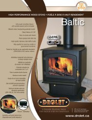
TECHNICAL SPECIFICATIONSCombustible:WoodRecommended Surface 500 to 2 100 ft 2(46 to 195 m 2 )Heating Capacity* : E.P.A :Seasoned cordwood:30 800 BTU/h(9.02 kW)85 000 BTU/h(24.91kW)Optimum efficiency : 75 %Emissions:5.7 g/hColors :Flat BlackFlue Pipe Diameter :6’’ (152 mm)Chimney type :2 100°F (650 °C)Minimum Chimney Height : 12’ (3,66 m)Maximum Log Length :19 1/2’’ (495 mm)DimensionsOverall:W x D x HBaltic:23 3/4 x 35 x 31 1/4 "(603 x 889 x 794 mm)Myriad:23 3/4 x 34 x 31 3/8 "(603 x 864 x 797 mm)Austral:23 3/4 x 34 x 30 3/8 "(603 x 864 x 772 mm)Legend:23 3/4 x 35 x 30 1/4 "(603 x 889 x 768 mm)Combustion Chamber :Baltic, Myriad, Austral, (Legend):Door Opening:Pyroceram Glass Door :Weight:Volume:All Models:All Models:Austral:Baltic:Legend:Myriad:W x D18 1/2 x 21 1/4 ", (18 1/2 x 20 1/4 ")(470 x 540 mm), (470 x 514 mm)3.279 ft 3 (0,092 m 3 ), (3.373 ft 3 (0,095 m 3 ))W x H15 1/2 x 10 3/4 "(394 x 273 mm)W x H15 3/16 ’’ x 11 1/4 ’’(386 x 286 mm)342 lbs (116 Kg)388 lbs (188 Kg)383 lbs (188 Kg)381 lbs (188 Kg)OPTIONSThermodiscOutside air intake kitPART NUMBERAll Models: AC05530All Models: AC020804
*Why is the BTU indicated on the EPA label smaller than the one advertised?You will notice a difference between the BTU output as indicated on the unit’s white EPA label affixed to the glassand the BTU as advertised on our web site and/or product literature. The maximum BTU output we advertise for thisunit is what will be obtained with a full load of seasoned cordwood inserted inside the firebox. The EPA output, onthe other hand, is what has been obtained during emissions testing. The EPA test procedure requires that a specialtype of wood be used and positioned inside the firebox in a manner that does not represent the way the fireboxvolume would normally be utilized using seasoned cordwood. The EPA test load is typically much smaller. Hence,the BTU as per the EPA label is reduced. The BTU output that should be considered by a normal user is the one weadvertise for seasoned cordwood.5
ASSEMBLYBALTICPedestal Base Installation:1. Slide the front part of the pedestalbase around the pedestal and fixthe rear part with the two suppliedscrews.2. Slide the ash pan in position.Side Panels and Ash Lip Installation:3. Start by fixing the front part of thedecorative side in the two clipswelded on the sides of the fire box.4. Then, fix the back of the decorativeside with two screws and washerssupplied. Line up the decorativeside parallel to the side of theappliance.7
AUSTRAL, LEGEND AND MYRIADAsh Pan Installation:8
DOOR ADJUSTMENTIn order for your stove to operate properly, the door should be adjusted periodically to providean air tight fit. To adjust:• Remove the lock pin (spring pin) by pulling and turning it using pliers ("wise grip")• Turn the handle counter clock wise one turn to increase pressure• Re-install the lock pin (spring pin) with a small hammerFigure 1: Door Adjustment9
INSTALLATIONSAFETY NOTICE• IF THIS STOVE IS NOT PROPERLY INSTALLED, A HOUSE FIRE MAY RESULT. TO REDUCE THE RISK OFFIRE, FOLLOW THE INSTALLATION INSTRUCTIONS. FAILURE TO FOLLOW INSTRUCTIONS MAY RESULT INPROPERTY DAMAGE, BODILY INJURY, OR EVEN DEATH.• CONSULT YOUR MUNICIPAL BUILDING DEPARTMENT OR FIRE OFFICIALS ABOUT RESTRICTIONS ANDINSTALLATIONS REQUIREMENTS IN YOUR AREA.• HAVE A FIRE EXTINGUISHER IN A CONVENIENT LOCATION AND USE SMOKE DETECTORS IN THE ROOMWHERE YOUR STOVE IS INSTALLED. THEY CAN SOMETIMES BE ACTIVATED BY SMALL AND NORMALWISPS OF SMOKE THAT CAN COME OUT OF THE STOVE AT THE IGNITION OR REFUELING. FOR THISREASON DO NOT PUT THEM DIRECTLY OVER THE UNIT OR WITHIN ONLY A FEW FEET FROM THE STOVE.• KEEP FURNITURE AND DRAPES WELL AWAY FROM THE STOVE.• NEVER USE GASOLINE, GASOLINE-TYPE LANTERN FUEL, KEROSENE, CHARCOAL LIGHTER FLUID, ORSIMILAR LIQUIDS TO START OR "FRESHEN UP" A FIRE. KEEP ALL SUCH LIQUIDS WELL AWAY FROM THESTOVE.• IN THE EVENT OF A CHIMNEY FIRE, PUSH THE AIR CONTROL FULL CLOSED TO DEPRIVE THE FIRE OFOXYGEN. CALL THE FIRE DEPARTMENT.• DO NOT CONNECT TO ANY AIR DISTRIBUTION DUCT OR SYSTEM.• A SOURCE OF FRESH AIR INTO THE ROOM OR SPACE HEATED SHALL BE PROVIDED WHEN REQUIRED.• DO NOT USE COMPONENTS OTHER THAN THOSE SPECIFIED IN THIS MANUAL.POSITIONING THE STOVEIt is very important to position the wood stove as close as possible to the chimney, and in anarea that will favor the most efficient heat distribution possible throughout the house. The stovemust therefore be installed in the room where the most time is spent, and in the most spaciousroom possible. Recall that wood stoves produce radiating heat, the heat we feel when we areclose to a wood stove. A wood stove also functions by convection, which is through thedisplacement of hot air accelerated upwards and its replacement with cooler air. If necessary,the hot air distribution from the stove may be facilitated by the <strong>installation</strong> of a blower.The wood stove must not be hooked up to a hot air distribution system since anexcessive accumulation of heat may occur.A wood stove must never be installed in a hallway or near a staircase, since it may blockthe way in case of fire or fall to respect required clearances.10
CLEARANCES TO COMBUSTIBLES AND FLOOR PROTECTORTo install your appliance correctly, it is extremely important to respect all clearances to anycombustibles as indicated on your stove’s certification label.Clearances to combustible materials(see figure 1.3 to match each letter to a clearance)CLEARANCES (SINGLE WALL PIPE)CANADA / USAMODEL A B C D E F K LAustral15’’/7’’(381/178mm)23’’(584 mm)16’’(406 mm)18’’/11’’(457/279mm)32’’(813 mm)25’’(635 mm)48’’(1220 mm)BalticLegendMyriad15’’/6’’(381/152mm)15’’/6’’(381/155mm)15’’/7’’(381/178mm)12’’(305 mm)12’’(305 mm)23’’(584 mm)9’’(229 mm)9’’(229 mm)16’’(406 mm)18’’/10’’(457/254mm)18’’/10’’(457/254mm)18’’/11’’(457/279mm)21’’(533 mm)21’’(533 mm)32’’(813 mm)18’’(457mm)18’’(457 mm)25’’(635 mm)48’’(1220 mm)48’’(1220 mm)48’’(1220 mm)84’’(213 cm)84’’(213 cm)84’’(213 cm)84’’(213 cm)CLEARANCES (DOUBLE WALL PIPE)CANADA / USAMODEL A B C D E F K LAustral6’’ 24’’ 17’’ 10’’ 33’’ 26’’ 48’’ 84’’(152 mm) (610 mm) (432 mm) (254 mm) (838 mm) (660 mm) (1220 mm) (213 cm)Baltic6’’ 12’’ 9’’ 10’’ 21’’ 18’’ 48’’ 84’’(152 mm) (305 mm) (229 mm) (254 mm) (533 mm) (457 mm) (1220 mm) (213 cm)Legend6’’ 12’’ 9’’ 10’’ 21’’ 18’’ 48’’ 84’’(152 mm) (305 mm) (229 mm) (254 mm) (533 mm) (457 mm) (1220 mm) (213 cm)Myriad6’’ 24’’ 17’’ 10’’ 33’’ 26’’ 48’’ 84’’(152 mm) (610 mm) (432 mm) (254 mm) (838 mm) (665 mm) (1220 mm) (213 cm)11
FIGURE 1.3 Clearances to combustible materials and floor protection12
FLOOR PROTECTORIf the stove is to be installed on top of a combustible floor, it must be guarded by a noncombustible material as shown on figure 1.3 (see the dotted line area).FLOOR PROTECTOR*CANADAUSAG 8’’ (203 mm) – Note 1 N/A (Canada only)H 8’’ (203 mm) N/A (Canada only)I 18’’ (457 mm)From door opening16’’ (406 mm)From door openingJ N/A (USA only) 8’’ (203 mm)M 8’’ (203 mm) N/A (Canada only)N N/A (USA only) Note 2*Steel with a minimum thickness of 0.015’’ (0.38 mm) or ceramic tiles sealed together withgrout. No protection is required if the unit is installed on a non-combustible floor (ex:concrete).Note 1 : The floor protection at the back of the stove is limited to the stove’s requiredclearance if such clearance is smaller than 8 inches (203 mm).Note 2 : Only required under the horizontal section of the connector. Must exceed eachside of the connector by at least 2 inches (51 mm).REDUCED CLEARANCES USING SHIELDINGYou may decrease the clearances by installing heat radiation shields between the walls or theceiling and the stove. These heat radiation shields must be installed permanently, and caninclude sheet metal, a rigid non-combustible sheet or a masonry wall.Clearances of not less than 1" (25 mm) and not more than 3" (76 mm) between the bottom ofthe shield and the floor and not less than 3" (76 mm) between the top of the shield and theceiling must be respected to allow vertical air circulation behind the shield. The shield mustextend 20" (500 mm) above the stove top and 18" (450mm) to each side of the stove (seegraphic 1).13
Following the <strong>installation</strong> of such a heat radiation shield, the clearances mentioned on the stovecertification plate may be reduced as stated in the following table.TYPE OF PROTECTIONSheet metal, a minimum of 0,024" (0,61mm) spaced outat least 1" (25mm) by non-combustible spacers(see graphic 2).Ceramic tiles, or an equivalent non-combustible materialon fire-proof supports spaced out at least 1" (25 mm) bynon-combustible spacers (see graphic 3).Ceramic tiles, or an equivalent non-combustible materialon fire-proof supports with a minimum of 0,024" (0,61mm) sheet metal backing spaced out at least 1" (25 mm)by non-combustible spacers (see graphic 4)Brick spaced out at least 1" (25 mm) by non-combustiblespacers (see graphic 5)Brick with a minimum of 0,024" (0,61 mm) sheet metalbacking spaced out at least 1" (25 mm) by noncombustiblespacers (see graphic 6).Reducing ClearancesWith ShieldingSides andRear/BackTop67% 50%50% 33%67% 50%50% N/A67% N/A14
Graphic 1A- Minimum clearance required between the appliance and an unshielded combustible ceiling.B- 20 in. (500 mm) minimum;C- 1 in. (25 mm) minimum;D- Between 1 in. and 3 in. (25 mm and 75 mm);E- 3 in.(75 mm) minimum;F- 18 in. (457 mm) minimum.1- Shielding;2- Non-combustible spacers;3- Ceiling protector;4- Combustible wall;5- Ceiling;6- Appliance (side view);7- Appliance (top view).15
A- 1 in.(25 mm) minimum;Graphic 21- Combustible wall;2- Non-combustible spacers;3- 0.024’’ (0.61mm) sheet metal.__________________________________________________________________A- 1 in. (25 mm) minimum;Graphic 31- Combustible wall;2- Non-combustible spacers;3- Non-combustible support;4- Ceramic tile or non-combustible material.__________________________________________________________________A- 1 in. (25 mm) minimum;Graphic 41- Combustible wall;2- Non-combustible spacer;3- 0.024’’ (0.61 mm) thick sheet metal;4- Non-combustible support;5- Ceramic tile or non-combustible material.16
A- 1 in. (25 mm) minimum;Graphic 51- Combustible wall;2- Non-combustible spacers;3- Brick.__________________________________________________________________Graphique 6A- 1 in. (25 mm) minimum;1- Combustible wall;2- Non-combustible spacers;3- 0.024’’ (0.61 mm) thick sheet metal;4- Brick.17
CHIMNEYYour wood stove may be hooked up with a factory built or masonry chimney. If you are using afactory built chimney, it must comply with UL 103 or ULC S629 standards; therefore it must be aType HT (2100 °F). It is extremely important that it be installed according to the manufacturer'sspecifications.If you are using a masonry chimney, it is important that it be built in compliance with thespecifications of the National Building Code. It must be lined with fire clay bricks, metal or claytiles sealed together with fire cement. (Round flues are the most efficient).The interior diameter of the chimney flue must be identical to the stove smoke exhaust. A fluewhich is too small may cause draught problems, while a large flue favors rapid cooling of thegas, and hence the build-up of creosote and the risk of chimney fires. Note that it is thechimney and not the stove which creates the draught effect; your stove's performance is directlydependent on an adequate draught from your chimney.The following recommendations may be useful for the <strong>installation</strong> of your chimney:1. Do not connect this unit to a chimney flue serving another appliance.2. It must rise above the roof at least 3' (0.9 mm) from the uppermost point of contact.3. The chimney must exceed any part of the building or other obstruction within a 10'(3.04 m) distance by a height of 2' (0.6 m).4. Installation of an interior chimney is always preferable to an exterior chimney. Indeed,the interior chimney will, by definition, be hotter than an exterior chimney, beingheated up by the ambient air in the house. Therefore the gas which circulates willcool more slowly, thus reducing the build-up of creosote and the risk of chimney fires.5. The draught caused by the tendency for hot air to rise will be increased with aninterior chimney.6. Using a fire screen at the extremity of the chimney requires regular inspection in orderto insure that it is not obstructed thus blocking the draught, and it should be cleanedwhen necessary.7. Follow pipe manufacturer’s instruction to maintain an effective vapour barrier wherechimney or other component penetrates to the exterior of the structure.WARNINGCHIMNEY AND CHIMNEY CONNECTOR MUST BE GOOD CONDITION AND KEPT CLEAN.CHIMNEY MUST BE REMOVED TO ALLOW TRANSPORTATION OF A MOBILE HOME.18
CHIMNEY CONNECTORYour chimney connector (commonly called stove pipe) and chimney must have the samediameter as the stove’s exhaust outlet. The stove pipe must be made of aluminized or cold rollsteel with a minimum 24-gauge thickness (0.021" or 0.53 mm). It is strictly forbidden to usegalvanized steel.The following recommendations may be useful for the <strong>installation</strong> of your chimney connector:• Your chimney connector should be assembled in such a way that the male end (crimped) faces down toprevent creosote dripping outside the joints. Attach each of the sections to one another with threeequidistant metal screws. Also use three equidistant metal screws to attach the connector to the stove’sexhaust collar. See Figure 2.3 (A) and Figure 2.3 (B).• The pipe must be short and straight. All sections installed horizontally must slope at least ¼ inch per foot,with the upper end of the section toward the chimney. See Figure 2.3 Detail B.• To insure a good draft, the total horizontal length of the connector should never exceed 8' to 10' (2.4 to3.04 m). In the case of vertical <strong>installation</strong>, the total length of the connector can be much longer andconnected without problem to the chimney at the ceiling level.• There should never be more than two 90 degrees elbows in the whole connector and chimney system.Never start with a 90 o elbow. Always go up vertically for at least 2 feet from the flue spigot before using a90 o elbow.• The connector must not pass through any combustible material, nor may it pass through a concealedspace (such as an attic, roof space, or closet). If passing through a wall, ceiling, or into a masonry chimney,use either chimney components listed for that specific use, or means acceptable to local authoritieshaving jurisdiction over the <strong>installation</strong>.• Installation of a "barometric draft stabiliser" (fireplace register) on a connector is not recommended.FIGURE 2.3 (A) Connecting Sections19
FIGURE 2.3 (B) Minimum Slope• The assembly should be as short and direct as possible between the stove and chimney (See figure 2.4(A)). The use of two 45 degree elbows (See figure 2.4 (C)) is often preferable to a single 90 degree elbow(See figure 2.4 (B)) because less turbulence is created in the exhaust flow and they result in less horizontalrun.(A) (B) (C)FIGURE 2.4 The use of elbows20
DRAFTYour E.P.A <strong>Drolet</strong> stove’s performance will be optimised if it is installed with a chimney (flue)system that provides an adequate draft. The draft is the force that moves air from the applianceup through the chimney and is predominantly affected by the height and diameter of thechimney, as well as the stack temperatures of the stove. If you test the draft using a pressuregauge, the reading should be between .05 - .07 inches of water column (w.c.) at a medium-highfire. A draft measure of less than .03" w.c. will cause operational difficulties while too much draft(greater than .10" w.c.) will result in over-firing of the stove. This can result in excessiveoperating temperatures. In this case, the <strong>installation</strong> of elbows totaling no more than 180° (ex.: 2x 30° elbows, 2 x 45° elbows or 2 x 90° elbows) can be installed to help reduce excessive draft.If the addition of elbows is not sufficient, a manual damper can be installed in the vertical fluepipe.21
TYPICAL INSTALLATIONSFACTORY BUILT CHIMNEY:RAIN CAPROOF FLASHING18" CLEARANCEWALL RADIATION SHIELDRADIATION SHIELDWALL SUPPORTCEILING SUPPORTWall <strong>installation</strong>Vertical <strong>installation</strong>22
MASONRY CHIMNEY:You can also install your stove using your existing masonry chimney. To do so, follow theguidelines below. You may want to use a factory-built thimble, or construct your own brickthimble. If you are using a masonry chimney, it is important that it be built in compliance with thespecifications of the Building Code in your region. It must normally be lined with fire clay bricks,metal or clay tiles sealed together with fire cement. (Round flues are the most efficient).Clay linerThimbleClean outdoor23
FACTORY BUILT THIMBLE:24
BRICK THIMBLE:25
OUTSIDE COMBUSTION AIRYour DROLET stove is approved to be installed with an outside air intake which is necessary fora mobile home. This type of <strong>installation</strong> is also required in air tight houses and houses withnegative pressure problems. You can purchase this option through your DROLET dealer.Make sure to specify this part number: #AC02080. Installation instructions are supplied with theair intake kit.Outside combustion air may be required if:1. Your stove does not draw steadily, smoke rollout occurs, wood burns poorly, or backdraftsoccur whether or not there is combustion present.2. Existing fuel-fired equipment in the house, such as fireplaces or other heating appliances,smell, do not operate properly, suffer smoke roll-out when opened, or back-drafts occurwhether or not there is combustion present.3. Opening a window slightly on a calm (windless) day alleviates any of the abovesymptoms.4. The house is equipped with a well-sealed vapour barrier and tight fitting windows and/orhas any powered devices that exhaust house air.5. There is excessive condensation on windows in the winter.6. A ventilation system is installed in the house.WARNINGS for use in MOBILE HOMES:• DO NOT INSTALL IN BEDROOM.• THE STRUCTURAL INTEGRITY OF THE MOBILE HOME FLOOR, WALL, AND CEILING/ROOF MUST BEMAINTAINED.• THE STOVE MUST BE ATTACHED TO THE STRUCTURE OF THE MOBILE HOME.• INSTALL IN ACCORDANCE WITH 24 CFR, PART 3280 (HUD).• USE A FACTORY BUILT CHIMNEY THAT COMPLY WITH UL 103 OR ULC S629 STANDARDS; THEREFOREIT MUST BE A TYPE HT (2100 °F).26
WOODSTOVE UTILISATIONYour heating unit was designed to burn wood only; no other materials should be burnt. Wastesand other flammable materials should not be burnt in your wood stove. Any type of wood maybe used in your stove, but specific varieties have better energy yields than others. Pleaseconsult the following table in order to make the best possible choice.Average Energy Yield Of One Air Dried Cord Of Cut WoodHigh energy yieldMedium energy yieldLow energy yieldData provided by Energy, Mines and Resources - CanadaWood speciesEnergy yield(millions of BTU/cord)Oak 29Sugar Maple 28Beech 26Yellow birch 25Ash 24Elm 23Larch (Tamarack) 23Red Maple 23Douglas red fir 23Silver birch 22Alder 18Poplar 17Hemlock 17Spruce 17Pine 17Bass 16Fir 13IT IS EXTREMELY IMPORTANT THAT YOU USE DRY WOOD ONLY IN YOUR WOODSTOVE. The wood must have dried for 9 to 15 months, such as the humidity content (in weight)is reduced below 20% of the weight of the log. It is very important to keep in mind that even ifthe wood has been cut since one, two or even more years, it is not necessarily dry, if it has beenstored in poor conditions; under extreme conditions, it may even rot instead of drying. The vastmajority of the problems related to the operation of a wood stove are caused by the fact that thewood used was too damp or had dried in poor conditions. These problems can be:• ignition problems• creosote build-up causing chimney fires• low energy yield• blackened windows• incomplete log combustionSmaller pieces of wood will dry faster. All logs exceeding 6" in diameter should be split. Thewood should not be stored directly on the ground. Air should circulate through the cord. A 24"to 48" air space should be left between each row of logs, which should be placed in the sunniestlocation possible. The upper layer of wood should be protected from the element but not thesides.27
TESTING YOUR WOODWhen the stove is thoroughly warmed, place one piece of split wood (about five inches indiameter) parallel to the door on the bed of red embers. Keep the air control full open by pullingon it and close the door. If ignition of the piece is accomplished within 90 seconds from the timeif was placed in the stove, your wood is correctly dried. If ignition takes longer, your wood isdamp. If your wood hisses and water or vapour escapes at the ends of the piece, your wood issoaked or freshly cut. Do not use this wood in your stove. Large amounts of creosote could bedeposited in your chimney, creating potential conditions for a chimney fire.THE FIRST FIRESThe fresh paint on your stove needs to be cured to preserve its quality. Once the fuel charge isproperly ignited, only burn small fires in your stove for the first four hours of operation. Neveropen the air control more than necessary to achieve a medium burn rate.Make sure that there’s enough air circulation while curing the stove. The odours could besmelled during the 3 or 4 first fires. Never start your stove outside. You will not be able to see ifyou are over heating. The smoke resulting from the paint curing process is not toxic.IGNITIONAfter making sure that the stove air intake controls are fully open (completely pull-out towardsyou), place several rumpled sheets of paper in the centre of the combustion chamber. Place 8to 10 pieces of small dry kindling wood over the paper in the form of a tent. You may also placea few pieces of heating wood, but choose the smaller ones. No chemical product should beused to light the fire.Before igniting the paper and kindling wood, it is recommended that you warm up the chimney.This is done in order to avoid back draft problems often due to negative pressure in the house.If such is the case, open a window slightly near the stove and twist together a few sheets ofnewspaper into a torch. Light up this paper torch and hold it as close as possible to the mouthof the pipe inside the combustion chamber to warm up the chimney. Once the updraftmovement is initiated, you are ready to ignite the stove by lighting the paper and kindling woodinside the combustion chamber.We therefore advise you to leave the door slightly opened (1/4") for a 10 to 30 minutes period,under supervision, in order to allow for good combustion. After this time, you must close thedoor and progressively adjust the air control to obtain the desired temperature.28
HEATINGControlled combustion is the most efficient technique for wood heating because it enables youto select the type of combustion you want for each given situation. The wood will burn slowly ifthe wood stove air intake control is adjusted to reduce the oxygen supply in the combustionchamber to a minimum. On the other hand, wood will burn quickly if the air control is adjustedto admit a larger quantity of oxygen in the combustion chamber. The air intake control on yourstove is very simple. If you pull on it out completely towards you, it is fully open. If you push onit until it stops the combustion air is reduced to a minimum.Your DROLET stove burnt between .954 kg\h and 2.556 kg\h. of wood during EPA testing. Realoperating conditions may give very different results than those obtained in the lab according tothe species of wood used, its moisture content, the size and density of the pieces, the length ofthe chimney, altitude and outside temperature.WARNINGS• NEVER OVERFIRE YOUR STOVE. IF ANY PART OF THE STOVE STARTS TO GLOW RED, OVER FIRING ISHAPPENING. READJUST THE AIR INTAKE CONTROL AT A LOWER SETTING.• THE INSTALLATION OF A LOG CRADLE IS NOT RECOMMENDED IN YOUR DROLET WOOD STOVE.• NEVER PUT WOOD ABOVE THE FIREBRICK LINING OF THE FIREBOX.• NEVER STORE WOOD WITHIN STOVE INSTALLATION CLEARANCES OR WITHIN THE SPACE REQUIRED FORCHARGING AND ASH REMOVAL.• DO NOT BUILD THE FIRE TOO CLOSE TO THE GLASS.• BURNING SOLID FUELS GENERATES CARBON MONOXIDE IN LOW CONCENTRATION. THIS GAS ISEVACUATED IN THE FLUE SYSTEM. IN HIGHER CONCENTRATIONS, CARBON MONOXIDE IS TOXIC AND MAYCAUSE DEATH. TO PREVENT THIS, ENSURE THAT YOUR FLUE SYSTEM IS GASTIGHT.• BURN WOOD ONLY IN THIS STOVE. SOME OTHER FUELS MAY BE HIGHLY VOLATILE, WHICH MAY CAUSEMORE EMBERS TO ENTER THE EXHAUST VENTING SYSTEM CAUSING A HAZARDOUS SITUATION. OTHERFUELS TYPE, SUCH AS CHARCOAL, CAN CREATE A HIGHER CONCENTRATION OF CARBON MONOXIDELEADING TO POTENTIAL POISONING.• MAINTAIN PROPER VENTILATION. IT IS IMPORTANT THAT ADEQUATE OXYGEN BE SUPPLIED TO THE FIREFOR PROPER COMBUSTION. DURING THE WINTER SEASON, MAKE SURE THAT THE FRESH AIR INTAKE ISFREE OF ANY ICE AS THIS WILL STARVE THE FIRE OF AIR AND PREVENT THE PROPER OPERATION OF THESTOVE.• THE HEAT FLOWING THROUGH THE FLUE SYSTEM CREATE A NEGATIVE PRESSURE IN THE ROOM. ITDRAWS AIR FROM THE INSIDE TO THE OUTSIDE. IN THE SAME WAY, OTHER APPLIANCES CAN ALSOCREATE A BIGGER NEGATIVE PRESSURE. IN THIS CASE, AS THE AIR NATURALLY FLOWS FROM HIGHPRESSURE POINT TO LOW PRESSURE POINT, THE BIGGER NEGATIVE PRESSURE MAY DRAW THE SMOKEFROM THE INSIDE OF THE STOVE INTO THE ROOM. THE STOVE CAN ALSO AFFECT OTHER VENTILATIONAPPLIANCES, CAUSING THE SAME EFFECT TO THEM.29
RELOADINGOnce you have obtained a good bed of embers, you should reload the unit. In order to do so,open the air controls to maximum a few seconds prior to opening the stove's door. Thenproceed by opening the door very slowly; open it one or two inches for 5 to 10 seconds, beforeopening it completely to increase the draught and thus eliminate the smoke which is stagnant ina state of slow combustion in the stove. Then bring the red embers to the front of the stove andreload the unit.For optimal operation of your wood stove, we recommend you to operate it with a wood loadapproximately equivalent to the height of fire bricks.It is important to note that wood combustion consumes ambient oxygen in the room .In the caseof negative pressure, it is a good idea to allow fresh air in the room, either by opening a windowslightly or by installing a fresh air intake system on an outside wall. Refer to page 16 of thepresent manual.In order to achieve an optimum efficiency from your unit, we suggest that you operate it with theair control completely closed. Make sure that you have a good fire going and an adequateember bed before you completely close the air control. Use a chimney thermometer ifnecessary. Closing the air control too soon will lower combustion efficiency and may cause thefire to die out. The addition of a blower (if not already included) is highly recommended tomaximize your unit’s efficiency.CREOSOTE FORMATION AND NEED FOR REMOVALWhen wood is burned slowly, it produces tar and other organic vapours, which combine withexpelled moisture to form creosote. The creosote vapours condense in the relatively coolchimney flue of a slow-burning fire. As a result, creosote residue accumulates on the flue lining.When ignited this creosote makes an extremely hot fire. When burning wood, the chimneyconnector and chimney should be inspected at least once every two months during the heatingseason to determine if a creosote build-up has occurred.We strongly recommend that you install a magnetic thermometer on your smoke exhaust pipe,approximately 18" above the stove. This thermometer will indicate the temperature of your gasexhaust fumes within the smoke exhaust system. The ideal temperature for these gases issomewhere between 275 o F and 500 o F. Below these temperatures, the build-up of creosote ispromoted. Above 500 degrees, heat is wasted since a too large quantity is lost into theatmosphere.TO PREVENT CREOSOTE BUILD UP• Always burn dry wood. This allows clean burns and higher chimney temperatures, thereforeless creosote deposit.• Leave the air control full open for about 10 min. every time you reload the stove to bring itback to proper operating temperatures. The secondary combustion can only take place ifthe firebox is hot enough.• Always check for creosote deposit once every two months and have your chimney cleanedat least once a year.30
USE OF THE BYPASS DAMPERYour stove is equipped with a bypass damper. This feature should be used, if needed, uponstart-up of the stove to help heat-up the chimney faster. The bypass damper should be closedas soon as there is a fire going inside the firebox and smoke is moving upward through theexhaust system. The bypass damper should also be used upon reloading to avoid smokespillage into the room. Before reloading your stove, open the primary air intake controlcompletely and then, open the bypass damper. Wait for approximately 10 to 15 seconds andopen the stove door. Close the bypass damper when you are finished reloading. Never leavethe bypass damper open under any condition unless you are building a fire or reloadingthe unit. To open the by-pass damper, insert the removable handle into the small rodextension located on the left-end side of the unit (Figure 1). Turn the handle toward the bottomto open the damper (Figure 2). Turn the handle toward the top to close the damper (Figure 3).Figure 1Figure 2 Figure 3CAUTIONS:• NEVER LEAVE THE REMOVABLE HANDLE INTO THE SMALL ROD EXTENSION UNLESS YOU ARE BUILDING AFIRE OR RELOADING THE UNIT.31
ASH DISPOSALAshes should be removed from the stove every few days or when ashes get to 2 to 3 inchesdeep. Always empty the stove when it is cold, such as in the morning.Always dispose of ashes in a metal container with a tight fitting lid. Other waste shall not beplaced in this container. Place this container on a non combustible floor or on the ground, wellaway from all combustible materials, pending final disposal. If the ashes are disposed of byburial in soil or otherwise locally dispersed, they should be retained in the close container untilall cinders have thoroughly cooled.CAUTIONS:• ASHES COULD CONTAIN HOT EMBERS EVEN AFTER TWO DAYS WITHOUT OPERATING THE STOVE.• THE ASH PAN CAN BECOME VERY HOT. WEAR GLOVES TO PREVENT INJURY.• NEVER BURN THE STOVE WITH THE ASH TRAP OPEN. THIS WOULD RESULT IN OVER FIRING THE STOVE.DAMAGE TO THE STOVE AND EVEN HOUSE FIRE MAY RESULT.FAN (BLOWER) OPERATIONAllow the stove to reach operating temperature (approximately one hour), before turning on thefan. The increased airflow from the fan will cool the firebox and affect the start-up combustionefficiency if the fan is turned on too quick.It is possible to make an automatic activation of the blower with the <strong>installation</strong> of an optionalbasic thermodisc kit AC05530 or a quick connect thermodisc kit AC02055.CAUTIONS:• ENSURE THAT THE FAN’S OR THERMODISC’S POWER CORD ARE NOT IN CONTACT WITH ANY SURFACEOF THE STOVE TO PREVENT ELECTRICAL SHOCK OR FIRE DAMAGE. DO NOT RUN ANY POWER CORDBENEATH THE STOVE.32
MAINTENANCEYour <strong>Drolet</strong> stove is a high efficiency stove and therefore requires little maintenance. It isimportant to perform a visual inspection of the stove every time it is emptied, in order to insurethat no parts have been damaged, in which case repairs must be performed immediately.GLASS• Inspect the glass regularly in order to detect any cracks. If you spot one, turn thestove off immediately. Do not abuse the glass door by striking or slamming shut. Donot use the stove if the glass is broken.• If the glass on your stove breaks, replace only with glazing supplied from the <strong>Drolet</strong> dealer.• To replace the glass, remove the screws retaining the glass mouldings inside the door.Remove the mouldings and replace the damaged piece with a new one. Perform theprocedure backwards after replacing. When replacing the glass, you should change theglass gasket to make sure you keep it sealed.• Never wash the glass with a product that may scratch. Use a specialized product, availablein the stores where wood stoves are sold.• The glass should be washed only when cold.• Under normal operating conditions, the glass is designed to stay clean. Glass cleaning maybe required when burning damp wood. Furthermore, small creosote or soot accumulationmay occur in the lower end corners of the glass when burning the stove with the air control atthe minimum setting. This is normal. The glass will clean itself when burning a hot fireduring one hour or more with the air control at its maximum setting. Nevertheless, cleaningthe glass on a regular basis is recommended to prevent thicker creosote or sootaccumulation that can be very hard to remove.GASKETINGIt is recommended that you change the door gasket (which makes your stove door air tight)once a year, in order to insure good control over the combustion, maximum efficiency andsecurity. To change the door gasket, simply remove the damaged one. Carefully clean theavailable gasket groove, apply a high temperature silicone sold for this purpose, and install thenew gasket. You may light up your stove again approximately 24 hours after having completedthis operation.WARNING:• NEVER OPERATE THE STOVE WITHOUT A GASKET OR WITH A BROKEN ONE. DAMAGE TO THE STOVE OREVEN HOUSE FIRE MAY RESULT33
PAINTOnly clean your stove with a dry soft cloth that will notharm the paint finish.If the paint becomes scratched or damaged, it is possible to give your wood stove a brand newlook, by repainting it with a 1200 o F heat resistant paint. For this purpose, simply scrub thesurface to be repainted with fine sand paper, clean it properly, and apply thin coats (2) of paintsuccessively. Refer to page 18 of the present manual for the paint curing process.CHIMNEYCall a professional chimney sweep, or go to your local <strong>Drolet</strong> dealer, purchase a chimney brush,and have the chimney cleaned. Regular chimney (flue) maintenance, as well as good burningpractices, is required to prevent chimney fires.34
BRICK LAYOUTITEM PART # DESCRIPTION QTY1 29015 4 X 9 BRICK 212 PL36022 4 X 5 3/8 BRICK 13 PL36054 4 X 9 BRICK (CUT) 24 SE16059 ASH DUMP CAP 135
DROLE LIMITED LIFETIME WARRANTYThe warranty of the manufacturer extends only to the original consumer purchaser and is not transferable. Thiswarranty covers brand new products only, which have not been altered, modified nor repaired since shipment fromfactory. Proof of purchase (dated bill of sale), model name and serial number must be supplied when making anywarranty claim to your DROLET dealer.This warranty applies to normal residential use only. Damages caused by misuse, abuse, improper<strong>installation</strong>, lack of maintenance, over firing, negligence, accident during transportation, power failures,downdrafts, or venting problems are not covered by this warranty.This warranty does not cover any scratch, corrosion, warping, or discoloration caused by over firing, abrasives or chemicalcleaners. Any defect or damage caused by the use of unauthorized parts or others than original parts void this warranty. Anauthorized qualified technician must perform the <strong>installation</strong> in accordance with the instructions supplied with this productand all local and national building codes. Any service call related to an improper <strong>installation</strong> is not covered by this warranty.The manufacturer may require that defective products be returned or that digital pictures be provided to support theclaim. Returned products are to be shipped prepaid to the manufacturer for investigation. If a product is found to bedefective, the manufacturer will repair or replace such defect. Transportation fees to ship the product back to thepurchaser will be paid by the manufacturer. Repair work covered by the warranty, executed at the purchaser’sdomicile by an authorized qualified technician requires the prior approval of the manufacturer. Labour cost and repairwork to the account of the manufacturer are based on predetermined rate schedule and must not exceed thewholesale price of the replacement part. All parts and labour costs covered by this warranty are limited according tothe table below.The manufacturer at its discretion may decide to repair or replace any part or unit after inspection and investigation ofthe defect. The manufacturer may, at its discretion, fully discharge all obligations with respect to this warranty byrefunding the wholesale price of any warranted but defective parts. The manufacturer shall in no event be responsiblefor any special, indirect, consequential damages of any nature, which are in excess of the original purchase price ofthe product. A one-time replacement limit applies to all parts benefiting from a lifetime coverage. This warranty appliesto products purchased after March 1 st , 2009.DESCRIPTIONWARRANTY APPLICATIONPARTS LABOURCombustion chamber (welds only) and castings. Lifetime 3 yearsStainless steel firebox components, secondary air tubes*, surroundsand heat shields, ash drawer, steel legs, pedestal, trims (aluminum5 years 3 yearsextrusions), plating* (defective manufacture), and convector air-mate.Carbon steel firebox components, glass retainers, handle assembly,C-Cast baffle*, and vermiculite baffle*.3 years 1 yearStandard blowers, heat sensors, switches, rheostat, wiring, and othercontrols.2 years 1 yearOptional blowers, ceramic glass (thermal breakage only*), paint(peeling), gaskets, insulation, and ceramic fibre blankets.1 year n/aFirebrick n/a n/a*Pictures requiredShall your unit or a components be defective, contact immediately your DROLET dealer. Prior to your call make sureyou have the following information necessary to your warranty claim treatment:• Your name, address and telephonenumber;• Bill of sale and dealer’s name;• Serial number and model name as indicated onthe nameplate fixed to the back of your unit;• Nature of the defect and any relevant information.Before shipping your unit or defective component to our plant, you must obtain from your DROLET dealeran Authorization Number. Any merchandise shipped to our plant without authorization will be refusedautomatically and returned to sender.36