ECO - 65 OWNER'S MANUAL - Drolet
ECO - 65 OWNER'S MANUAL - Drolet
ECO - 65 OWNER'S MANUAL - Drolet
- No tags were found...

Create successful ePaper yourself
Turn your PDF publications into a flip-book with our unique Google optimized e-Paper software.
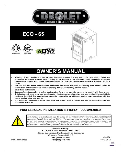
INTRODUCTIONThank you for purchasing the <strong>ECO</strong>-<strong>65</strong> pellet stove. You are now prepared to burn pellet inthe most efficient, convenient way possible. To achieve the safest, most efficient and mostenjoyable performance from your stove, you must do three things: 1) Install it properly; 2)Operate it correctly; and 3) Maintain it regularly. The purpose of this manual is to help you doall three.PLEASE read this entire manual before installation and use of this pellet fuel-burningroom heater. Failure to follow these instructions could result in property damage,bodily injury or even death.Keep this manual handy for future reference.Your <strong>Drolet</strong> <strong>ECO</strong>-<strong>65</strong> has been independently tested to ASTM E1509-04 StandardSpecification for Room Heaters, Pellet Fuel Burning Type, UL 1482-2010 and ULC-S627-00Standard for Solid Fuel Room Heaters, Oregon Administrative Rules for Mobile Homes (814-23-900 through 814-23-909) and Installation as a Stove Heater. This pellet stove, wheninstalled, must be electrically grounded in accordance with local codes, or in the absence oflocal codes, with the National Electrical Code, ANSI/NFPA 70 and CSA-C22.1.We recommend that our pellet hearth products be installed and serviced by professionalswho are certified in the United States by NFI (National Fireplace Institute®) or in Canada byWETT (Wood Energy Technology Transfer) or in Quebec by APC (Association desProfessionnels du Chauffage).The bottom-feed burner system of this appliance is designed and tested specifically for useonly with four different types of pellets: standard wood pellets, 100% bark pellets,sawdust/hay mix pellets, and switch grass pellets. This appliance is designed for residentialinstallation according to current national and local building codes as a freestanding roomheater. It is also approved as a mobile home heater. An outside combustion air source ismandatory.The stove will not operate using natural draft or without a power source for the blowersystems and fuel feed system and must not be burned with any type of coal.This stove is designed to provide the optimum proportions of fuel and air to the fire in order toburn free of smoke and soot. Any blockage of the air supply to or from the stove will seriouslydegrade its performance and will be evidenced by a smoking exhaust and a sooting window.For best operation, the ash content of the pellet fuel should be less than 1% and the calorificvalue approximately 8,200 BTU/LB. Others fuels with a high ash content will require a higherlevels of maintenance and cleaning.This appliance has been developed and built for residential supplementary heat source.Commercial and industrial use should be avoided.CAUTION: THE INFORMATION GIVEN ON THE CERTIFICATION LABEL AFFIXED TO THE APPLIANCEALWAYS OVERRIDES THE INFORMATION PUBLISHED, IN ANY OTHER MEDIA (OWNER’S<strong>MANUAL</strong>, CATALOGUES, FLYERS, MAGAZINES AND/OR WEB SITES).
SAFETY PRECAUTIONS DO NOT OPERATE YOUR STOVE IFYOU SMELL SMOKE COMING FROM IT.TURN IT OFF, MONITOR IT, AND CALLYOUR DEALER. NEVER USE GASOLINE,GASOLINE-TYPE LANTERN FUEL,KEROSENE, CHARCOAL LIGHTERFLUID, GARBAGE, NAPHTA, ENGINEOIL OR SIMILAR LIQUIDS TO STARTOR “FRESHEN UP” A FIRE IN THISSTOVE. KEEP ALL SUCH LIQUIDSWELL AWAY FROM THE STOVE WHILEIN USE. NEVER BLOCK FREE AIRFLOWTHROUGH THE OPEN VENTS OF THESTOVE. NEVER TRY TO REPAIR ORREPLACE ANY PART OF THE STOVEUNLESS INSTRUCTIONS ARE GIVEN INTHIS <strong>MANUAL</strong>. ALL OTHER WORKSHOULD BE DONE BY A TRAINEDTECHNICIAN. THE STOVE WILL NOT OPERATEDURING A POWER OUTAGE. IF ANOUTAGE DOES OCCUR, CHECK THESTOVE FOR SMOKE SPILLAGE ANDOPEN A WINDOW IF ANY SMOKESPILLS INTO THE ROOM. DISCONNECT THE POWER CORDBEFORE PERFORMING ANYMAINTENANCE OR REPAIRS ON THESTOVE.NOTE: TURNING THE STOVE “OFF”DOES NOT DISCONNECT ALL POWERFROM THE STOVE. DO NOT UNPLUG THE STOVE IFYOU SUSPECT A MALFUNCTION. TURNTHE STOVE OFF, PERIODICALLYINSPECT IT, AND CALL YOUR DEALER. CONTACT YOUR LOCAL BUILDINGOFFICIALS TO OBTAIN A PERMIT ANDINFORMATION ON ANY INSTALLATIONRESTRICTIONS OR INSPECTIONREQUIREMENTS IN YOUR AREA.NOTIFY YOUR INSURANCE COMPANYOF THIS STOVE AS WELL. KEEP FOREIGN OBJECTS OUT OFTHE HOPPER. DO NOT THROW THIS <strong>MANUAL</strong>AWAY. THIS <strong>MANUAL</strong> HAS IMPORTANTOPERATING AND MAINTENANCEINSTRUCTIONS THAT YOU WILL NEED ATA LATER TIME. ALWAYS FOLLOW THEINSTRUCTIONS IN THIS <strong>MANUAL</strong>. DO NOT PLACE CLOTHING,FURNITURES OR OTHER FLAMMABLEITEMS ON OR NEAR THE STOVE. THE VIEWING DOOR MUST BECLOSED AND LATCHED DURINGOPERATION. DO NOT OPERATE THE STOVE IF THEFLAME B<strong>ECO</strong>MES DARK AND SOOTY ORIF THE BURN POT OVERFILLS WITHPELLETS. TURN THE STOVE OFF,PERIODICALLY INSPECT IT, AND CALLYOUR DEALER. DO NOT TOUCH THE HOT SURFACESOF THE HEATER. CONTACT WITH UNITMAY CAUSE SKIN BURNS. KEEPCHILDREN AWAY FROM THE UNIT ANDEDUCATE ALL CHILDREN OF THEDANGER OF A HIGH TEMPERATURESTOVE. YOUNG CHILDREN SHOULD BESUPERVISED WHEN THEY ARE IN THESAME ROOM AS THE STOVE. IT IS R<strong>ECO</strong>MMENDED THAT THESTOVE BE UNPLUGGED WHEN NOT INUSE FOR EXTENDED PERIODS OF TIME(I.E. DURING THE SUMMER MONTHS). IFTHE STOVE IS INSTALLED IN A ROOMWITHOUT AIR CONDITIONING, OR IN ANAREA WHERE DIRECT SUNLIGHT CANSHINE ON THE UNIT, IT IS POSSIBLE THISCAN CAUSE THE TEMPERATURE OF THESTOVE TO RISE TO OPERATIONALLEVELS; ONE OF THE SENSORS COULDTHEN MAKE THE BLOWERS START ONTHEIR OWN. THE EXHAUST SYSTEM MUST B<strong>ECO</strong>MPLETELY AIRTIGHT AND PROPERLYINSTALLED. ALL VENT CONNECTORJOINTS MUST BE SEALED ANDFASTENED IN ACCORDANCE WITH THEPELLET PIPE MANUFACTURER'SINSTRUCTIONS TO ENSURE CONSISTENTPERFORMANCE AND AVOID SMOKE ANDASH SPILLAGE.
THIS UNIT MUST BE PROPERLYINSTALLED TO PREVENT THEPOSSIBILITY OF A HOUSE FIRE. THEINSTRUCTIONS MUST BE STRICTLYADHERED TO. DO NOT USEMAKESHIFT METHODS ORCOMPROMISE IN THE INSTALLATION. ALLOW THE STOVE TO COOLBEFORE CARRYING OUT ANYMAINTENANCE OR CLEANING. ASHESMUST BE DISPOSED IN A METALCONTAINER WITH A TIGHT LID ANDPLACED ON A NON COMBUSTIBLESURFACE WELL AWAY FROM THEHOME STRUCTURE. THIS STOVE MUST BE CONNECTEDTO A STANDARD 120 V., 60 HZGROUNDED ELECTRICAL OUTLET. DONOT USE AN ADAPTER PLUG ORSEVER THE GROUNDING PLUG. DONOT ROUTE THE ELECTRICAL CORDUNDERNEATH, IN FRONT OF, OR OVERTHE STOVE. THE EXHAUST SYSTEM SHOULDBE CHECKED, AT LEAST TWICE AYEAR FOR ANY BUILD UP OF SOOT ORCREOSOTE. YOUR STOVE REQUIRES PERIODICMAINTENANCE AND CLEANING. FAILURETO MAINTAIN YOUR STOVE MAY LEADTO SMOKE SPILLAGE IN YOUR HOME. THIS APPLIANCE IS DESIGNED ANDTESTED SPECIFICALLY FOR USE ONLYWITH FOUR DIFFERENT TYPES OFPELLETS: STANDARD WOOD PELLETS,100% BARK PELLETS, SAWDUST/HAYMIX PELLETS, AND SWITCH GRASSPELLETS. ANY OTHER TYPE OF FUELBURNED IN THIS HEATER WILL VOID THEWARRANTY AND SAFETY LISTING. THE STOVE MUST BE BOLTED TOTHE FLOOR, HAVE OUTSIDE AIR, ANDNOT BE INSTALLED IN A BEDROOM (PERH.U.D. REQUIREMENTS). CHECK WITHLOCAL BUILDING OFFICIALS. STOVE BUILDER INTERNATIONALINC. GRANTS NO WARRANTY, IMPLIEDOR STATED, FOR THE INSTALLATION ORMAINTENANCE OF YOUR STOVE, ANDASSUMES NO RESPONSIBILITY OF ANYCONSEQUENTIAL DAMAGE(S). IT IS MANDATORY TO CONNECTTHIS STOVE TO A 4¨ FRESH AIR INLETTO REDUCE THE RISK OF HOPPERBURN BACK CAUSED BY NEGATIVEPRESSURE.REGISTER YOUR WARRANTY ONLINETo receive full warranty coverage, you will need to show evidence of thedate you purchased your stove. Keep your sales invoice. We alsorecommend that you register your warranty online athttp://www.drolet.ca/en/service-support/warranty-registrationRegistering your warranty online will help us track rapidly the informationwe need on your stove.
TABLE OF CONTENTSSAFETY PRECAUTIONS ....................................................................................................................................... 31. INSTALLATION ......................................................................................................................................... 61.1. FEATURES ................................................................................................................................................ 61.2. PREPARATION ......................................................................................................................................... 61.3. CLEARANCES .......................................................................................................................................... 61.4. COMBUSTION AIR SUPPLY .................................................................................................................... 81.5. ANCHOR THE STOVE ............................................................................................................................ 101.6. VENTING ................................................................................................................................................. 101.6.1. Equivalent Vent Length (EVL) ............................................................................................................... 111.6.2. Installation Configurations .................................................................................................................... 12a) Horizontally through wall ................................................................................................. 12b) Vertically with new chimney system ................................................................................ 14c) Vertically into existing chimney system ........................................................................... 15d) Vertically into existing masonry fireplace ........................................................................ 15e) Installation through side of masonry chimney .................................................................. 162. OPERATION ............................................................................................................................................ 172.1. PROPER FUEL ........................................................................................................................................ 172.2. WHERE TO STORE BAGS OF PELLETS .............................................................................................. 172.3. PRE-START-UP CHECK ......................................................................................................................... 172.4. BUILDING A FIRE ................................................................................................................................... 172.5. LIGHTING PROCEDURE ........................................................................................................................ 182.6. UNIT CONTROLS (See Figure 16) .......................................................................................................... 182.7. OPENING DOOR ..................................................................................................................................... 192.8. CONVECTION BLOWER (ROOM AIR FAN) .......................................................................................... 192.9. IF THE STOVE RUNS OUT OF PELLETS .............................................................................................. 192.10. REFUELING ............................................................................................................................................. 202.11. SHUTDOWN PROCEDURE .................................................................................................................... 202.12. SAFETY FEATURES ............................................................................................................................... 202.13. OPERATING THE STOVE USING A THERMOSTAT ............................................................................ 202.13.1. Thermostat Installation .......................................................................................................................... 202.13.2. Thermostatic mode ................................................................................................................................ 212.14. OPERATING SAFETY PRECAUTIONS ................................................................................................. 223. MAINTENANCE ....................................................................................................................................... 243.1. CLEANING THE BURN POT AND THE AIR WASH INLET ................................................................... 243.2. MAINTENANCE OF THE COMBUSTION CHAMBER, HEAT EXCHANGERS AND BLOWERHOUSING .............................................................................................................................................................. 253.3. MAINTENANCE OF THE HEAT EXCHANGERS AND BLOWER HOUSING ....................................... 253.4. VENTING SYSTEM MAINTENANCE ...................................................................................................... 263.4.1. Dealing with a Chimney Fire ................................................................................................................. 263.4.2. Soot and Flyash – Formation and need for removal .......................................................................... 263.5. ASH REMOVAL ....................................................................................................................................... 273.5.1. ASH DISPOSAL AND USE OF AN ASH VACUUM ............................................................................... 273.6. DOOR ADJUSTMENT ............................................................................................................................. 273.7. DOOR GASKET MAINTENANCE ........................................................................................................... 283.8. GLASS CARE .......................................................................................................................................... 283.9. REMOVAL AND REPLACEMENT OF BROKEN DOOR GLASS .......................................................... 293.10. REMOVAL AND REPLACEMENT OF GASKETS ................................................................................. 313.11. R<strong>ECO</strong>MMENDED MAINTENANCE SCHEDULE .................................................................................... 384. TROUBLESHOOTING GUIDE ................................................................................................................ 395. ELECTRICAL DIAGRAM ........................................................................................................................ 455.1. FUSE ACCESS ........................................................................................................................................ 466. REPLACEMENT PARTS ......................................................................................................................... 47APPENDIX A ........................................................................................................................................................ 50APPENDIX B ........................................................................................................................................................ 51DROLET LIMITED LIFETIME WARRANTY ......................................................................................................... 52
1. INSTALLATION1.1. FEATURESDROLET <strong>ECO</strong>-<strong>65</strong> FREESTANDING PELLET STOVE Width: 24” Height: 41” Depth: 30” Weight: 375 lbs. Flue size: 4” Hopper Capacity: Up to 125 lbs. (This can varydepending on pellet size, length, and diameter) EPA status: < 4.5 g/h. Burn rate: 1.3 lbs to 7.9 lbs. per hour BTU range: 10,500 to <strong>65</strong>,000 Electrical consumption:o 5 Amps lighting cycleo 2.5 Amps. continuous duty Control board fuses: Main: 7.5A-250V fastblowo Convection blower: 5A-250V fastblowo Combustion blower: 3A-250V fastblowo Exhaust blower: 3A-250V fastblowo Auger 1: 3A-250V fastblowo Auger 2: 3A-250V fastblowo Ignitor : 5A-250V fastblow Electrical requirement: 120VAC 15A Approved installations: mobile home, conventional1.2. PREPARATIONFactory packaging must be removed, and some minorassembly work is required prior to installation for handle anddoor adjustment. Also, the stove must be leveled usingthreaded legs.1.3. CLEARANCESFIGURE 1Back wall installationFIGURE 2Corner installationThe <strong>Drolet</strong> <strong>ECO</strong>-<strong>65</strong> has been tested and listed for installationin residential and mobile home. (refer to figure 1 to 3)FLOOR PROTECTION: In the USA, the unit must be installedon a non-combustible floor pad extending at least 6 inches(155 mm) in front of the door opening and at least 6 inches(155 mm) on each side of the door opening. In Canada, theunit must be installed on a noncombustible floor pad extendingat least 18 inches (460 mm) in front of the door opening and atleast 8 inches (205 mm) at the back and on each side of theunit. The floor pad must have a thickness of at least 0.015''(0.38mm). NOTE: ceramic tile, or any tile, must be laid on acontinuous non combustible sheet to prevent the possibility ofembers falling through to the combustible floor if cracks orseparation should occur in the finished surface.Clearances are measured from the sides, back or face (dooropening) (refer to fig. 4). For ceiling clearance refer to figure 4.Door openingFIGURE 3Floor protectionClearances may only be reduced by means approved bythe regulatory authority.
DO NOT USE MAKESHIFT MATERIALS OR COMPROMISESIN THE INSTALLATION OF THIS UNIT.INSTALL VENT WITH CLEARANCES SPECIFIED BY THEVENT MANUFACTURER.This heating unit must serve as a supplementary heat source.An alternative heat source should be available in the home ifneeded. The manufacturer cannot be responsible for additionalheating costs associated with the use of an alternative heatsource.It is highly recommended that the user buys this product from aretailer who can provide installation and maintenance advices.We recommend leaving 24’’ on each sides of the appliance in order tofacilitate access for maintenance.FIGURE 4Celing clearanceCLEARANCES TO COMBUSTIBLESCANADAUSAA 2’’ (55 mm) 2’’ (55 mm)B 6’’ (155 mm) 6’’ (155 mm)C 2’’ (55 mm) 2’’ (55 mm)D 3’’ (80 mm) 3’’ (80 mm)CANADAFLOOR PROTECTORUSAE 18’’ (460 mm) 6’’ (155 mm)F N/A (USA only) 6’’ (155 mm)G 8’’ (205 mm) N/A (Canada only)H 8’’ (205 mm) N/A (Canada only)
1.4. COMBUSTION AIR SUPPLYIt is mandatory to connect this stove to an outsidecombustion air source to reduce the risk of hopperburn back caused by negative pressure. A insulated4” inside diameter metallic pipe, either flexible or rigid,must be attached to the inlet at the stove’s rear (referto figures 5, 6 & 7). A rodent guard (minimum ¼” wiremesh) must be used at the terminus (refer to figure 6).All connections must be secured and airtight by eitherusing the appropriately sized hose clamp and/or UL-181-AP foil tape. Also make sure that the fresh airdamper is open while the stove is running. The freshair intake damper is located at the back of the stoveright hand side (refer to figure 6.).For mobile home installations only: No combustion air supply may exceed 10 feet.Sources of Outside Combustion Air: A hole in floor near the back of the leading onto aventilated crawl space under the house. A hole in the wall behind the stove.FIGURE 5Rear viewFIGURE 6.The fresh air intake damper
FIGURE 7Fresh air supplyFIGURE 8Fresh air supply
1.5. ANCHOR THE STOVEThe stove must be anchored to the floor with screws. Please use the two holes located on each side of thepedestal. (See Fig. 9)FIGURE 9Anchor1.6. VENTINGIn Canada, we recommend that you use a listed pellet vent that meets the ULC S-609-M89/ORD C441-M90Standard.For the United States, we recommend that you use a listed pellet vent that meets the UL-641Standard.This unit can be vented in an existing factory-built or masonry chimney with the addition of a liner, provided thechimney is more than 4” in diameter. The liner should be listed and should meet the ULC S-635/640 standard inCanada and the UL-1777 standard in the USA. Refer to the instructions provided by the vent or chimneymanufacturer, especially when passing through a wall, ceiling, or roof.Your venting system should have at least one foot of vertical rise for each foot of horizontal run. Thetotal vertical rise should never be less than 3 feet (see Appendix A).This unit uses a pressurized exhaust system. All vent connector joints must be sealed and fastened. If ventedhorizontally, joints should be made gastight. Please consult the pellet pipe manufacturer’s instruction to ensureproper installation and consistent performance to avoid smoke and ash spillage.
DO NOT CONNECT THIS UNIT TO A CHIMNEY FLUE SERVING ANOTHER APPLIANCE.DO NOT INSTALL A FLUE DAMPER IN THE EXHAUST VENTING SYSTEM OF THIS UNIT.WARNING:WARNING:CAUTION:CAUTION:INSTALL VENT AT CLEARANCES SPECIFIED BY THE VENT MANUFACTURER.DO NOT INSTALL IN BEDROOMTHE STRUCTURAL INTEGRITY OF THE MANUFACTURED HOME FLOOR, WALL, ANDCEILING/ROOF MUST BE MAINTAINEDTHE CHIMNEY CONNECTOR SHALL NOT PASS TROUGH AN ATTIC OR ROOF SPACE,CLOSET OR SIMILAR CONCEALED SPACE, OR A FLOOR, OR CEILING.1.6.1. Equivalent Vent Length (EVL)The longer the run of pipe in your installation, thegreater the restriction in your system. A wider pipeis recommended when the system’s run is long. Always use 4” pipe if you have more than 15”Equivalent Vent Length (EVL). Horizontal runs shall not exceed 9 feet. Never exceed 30 feet of EVL.To calculate EVL, use the following conversionstable:Qty Type of pipe EVL equivalent(ft)1 90° elbow or “T” 51 45° elbow 31 ft Horizontal pipe run 11 ft Vertical pipe run 0.5NOTE: If the stove is located at an altitude of 3,000 feet or more, it isrecommended to use a 4'' diameter venting system if the ELV is 7 feet ormore.Here is an example on how to calculate the EVL ofyour installation. (See Figure 9):FIGURE 10Venting through wall(3 x 4’ of vertical length = 12’ x 0.5 = 6 EVL) +(1 x elbow or "T" = 5 EVL) +(2 x 1’ of horizontal length = 2 EVL)Total EVL = (6 + 5 +2) = 13. Therefore, the use ofa 3" pipe is permitted.Note: Do not include the exterior wall termination (swan neck) in thecalculation of the EVL.
1.6.2. Installation Configurationsa) Horizontally through wall(Refer to figures 10, 11, or 12)NOTE: Follow vent chimney manufacturer’s instructions.1. Position stove, adhering to clearances shown in Figures 1 & 2.2. Locate position of hole in wall; directly behind stove exhaust vent (refer to figure 5).3. Always maintain 3” clearance from combustible materials.4. Install Vent wall thimble per Vent manufacturer’s instructions.5. Attach enough piping to penetrate and extend at least 6 inches beyond the exterior wall. There shouldalways be at least one foot of vertical rise for each foot of horizontal run (see Appendix A). At least 3 feet ofvertical rise are needed in all cases. A longer vertical rise will favour a better exhaust.FIGURE 11Venting through wall6. To reduce the risk of smoke spillage, never terminate with a horizontal run. If your system terminates with ahorizontal run, add at least 3 feet of vertical rise (see Appendix A).7. Attach cap and seal outside wall thimbles with non-hardening waterproof mastic.Termination should not be located so that hot exhaust gases can be a hazard to children. Exhaust gases canreach temperatures of 500ºF and cause serious burns if touched.Do not locate terminations:
In Canada:a) less than 7 feet vertically above any public sidewalk, lane, street, right-of-way, stairway or landing;b) within 6 feet of a mechanical air supply inlet to a building;c) within 3 feet of a building opening or air inlet of another appliance;d) above a gas meter/regulator assembly within 3 feet horizontally of the vertical centerline of theregulatore) within 6 feet of any gas service regulator vent outlet or within 3 feet of an oil tank vent or an oil tankfill inlet;f) less than 1 feet above adjacent grade level or any adjacent surface that may support snow, ice, ordebris;g) within 3 feet of the property boundary; andh) underneath a veranda, porch, or deck.i) A clear space of at least 3 feet shall be provided from the termination to any building projection,adjacent wall, or any combustible materials such as trees, shrubs, fencing, etc.In the US:a) less than 3 feet above any forced air inlet located within 10 feet;b) less than 4 feet below or horizontally from, or one foot above, any door, window or gravity air inlet intoany building;c) less than two feet from an adjacent building and not less than 7 feet above grade when locatedadjacent to a public walkway. Mobile home installations must use a spark arrester. Other restrictionsmay apply, such as the need to maintain a minimum distance to a gas meter. See NFPA 211.FIGURE 12Venting through wallBasement installation
) Vertically with new chimney system(Refer to Figure 13)OPTION: To achieve a centered vertical installation, a 45º elbow and a clean-out tee can be used to offset thepipe from the exhaust outlet to the rear center of the stove.OPTION: Install Vent elbow in place of clean-out tee. Locate stove. Drop plumb bob to center of tee outlet, markpoint on ceiling. Install ceiling support and Vent pipe per Vent manufacturer’s instructions.1. Always maintain 3” clearance from combustible materials. When passing through additional floors orceilings, always install firestop spacer.2. After lining up for hole in roof, cut either a round or square hole in roof, always 3” larger all the way aroundpipe. Install upper edge and sides of flashing under roofing materials, nail to the roof along upper edge. Donot nail lower edge. Seal nail heads with flexible waterproof sealant.3. Apply flexible, waterproof sealant where the storm collar meets the vent. Slide storm collar down until it sitson the flashing. Seal and install cap. Mobile home installations must use a spark arrester.FIGURE 13Venting through roof
c) Vertically into existing chimney system(Refer to Figure 14)As an alternative, 4” Vent can be run inside existing chimney to termination (Figure 12). This is the preferredmethod.Follow guidelines for equivalent vent length.FIGURE 14Venting throughexisting chimneyd) Vertically into existing masonry fireplace(Refer to figure 15)NOTE: Follow Vent chimney manufacturer’sinstructions.1. Have the masonry chimney inspected by aqualified chimney sweep or installer to determineits structural condition.2. You will need a pipe length equal to the chimneyheight from the hearth. If outside combustion air isto be used, you will need a pipe length equal tothe chimney height plus 18 inches.3. Install a blanking plate and the chimney pipe, andif used the outside air pipe, as shown in Figure 13.4. Attach the adapter, a section of pipe and cleanouttee, making sure the cleanout tee is centered inthe chimney flue area. Use RTV, metallic tape,and a minimum of three self-taping screws at alljoint connections to ensure a tight seal.5. Position the stove, adhering to the clearances inFigures 1 & 2.Figure 15Venting through masonrychimney6. Measure and build chimney top plate. Cut out holes for chimney pipe, and if used the outside air pipe. Installand seal with non-hardening mastic to prevent water leakage. Install vent cap.
e) Installation through side of masonry chimney(Refer to figure 16)1. Position the stove, adhering to the clearances in Figures 1 & 2. Mark the center of the hole where the pipe isto pierce the masonry chimney.2. It will be necessary to break out the masonry around the location of the pipe center mark. Use a 5-inchdiameter hole for 4-inch pipe.3. Measure and build chimney top plate. Cut out holes for chimney and the outside air pipe.4. Install the tee on the bottom of the vertical pipe system and lower it down the chimney until the centerbranch of the tee is level with the center of the hole in the masonry, as shown in Figure 16.5. Install and seal the top plate from step 3 with non-hardening mastic. Slip the storm collar over the pipe, andwhile holding the pipe at the proper elevation, affix the collar with a minimum of three ¼” stainless steelsheet metal screws. Seal all joints and seams around the collar.6. Connect the horizontal pipe by pushing it through the hole in the masonry and lining it up with the branch inthe tee. Push the pipe into the tee while twisting it to lock it into the tee.7. If desired, once the horizontal pipe is in place, the space between the pipe and masonry may be filled withhigh-temperature grout.Install the trim collar. An adjustable pipe length and adapter may be needed to finish the connection to thestove.Figure 16Venting through side ofmasonry chimney
2. OPERATION2.1. PROPER FUELTHIS STOVE IS APPROVED FOR BURNING four different types of pellets: standard wood pellets, 100%bark pellets, sawdust/hay mix pellets, and switch grass pellets! Each type of pellet has its propertiesand will burn differently.The ash produced can also vary greatly. Factory-approved pellets are those ¼” or 5/16” in diameter and notover 1” long. Longer or thicker pellets sometimes bridge the auger flights, which prevents proper pellet feed.Burning other types of pellets is not permitted. It will violate the building codes for which the stove hasbeen approved and will void all warranties. The different types of pellets that have been tested in the <strong>Drolet</strong>Eco-<strong>65</strong> were made of the following types of biomass:Wood pelletsWood pellets, whether made of hard or soft wood, are easy to burn. The pellets used are the same type as theones used in most pellet stoves. They should produce a fairly small amount of ash.Wood and hay pelletsPellets made of wood and hay will produce more ash than straight wood pellets. The wood and hay pellets thathave been tested in your Eco-<strong>65</strong> consisted of 1/3 hay and 2/3 wood. Make sure that any wood and hay pelletsyou put in your Eco-<strong>65</strong> respect that mix (+/- 10%).Bark pellets100% bark pellets produce a hard crust that will be pushed into the ash drawer. Their ash content is very high.If you burn 100% bark pellets, make sure that the crust forming in front of the burn pot breaks and falls into theash drawer. Ignition may be a bit more difficult and it is possible that the stove needs a second ignition cycle toproperly light the bark pellets.Switch grass pelletsThe ash content of switch grass pellets may vary depending on when this type of biomass is harvested. Switchgrass will burn very clean. A crust will form in front of the burn pot. It should break easily and fall into the ashdrawer. The crust is light and friable. It will occupy quite a bit of volume into the ash drawer. For this reason, itis important to empty the ash drawer more frequently.2.2. WHERE TO STORE BAGS OF PELLETSWe recommend that you store your bags of pellets in a dry and well ventilated area if possible. Using dry pelletswill increase the performance of your stove. You may want to have a bag or two in the same room as your stovefor refuelling but make sure to respect the minimum clearances for combustible materials.2.3. PRE-START-UP CHECKRemove burn pot, making sure it is clean and none of the air holes are plugged. Clean the firebox, and thenreinstall burn pot. Clean door glass if necessary (a dry cloth or paper towel is usually sufficient). Never useabrasive cleaners on the glass or door. Check fuel in the hopper, and refill if necessary. Make sure that thefresh air inlet damper is open.2.4. BUILDING A FIRENever use a grate or other means of supporting the fuel. Use only the <strong>Drolet</strong> approved burn pot.NOTE: During the first few fires, your stove will emit an odor and a small amount of fumes as the hightemperature paint cures or becomes seasoned to the metal. Maintaining smaller fires will minimize this. Avoidplacing items on stovetop during this period because paint could be affected. Make sure the room is wellventilated.Open windows. Odors and fumes released during this process are unpleasant but they arenot toxic.
2.5. LIGHTING PROCEDUREa. Fill hopper and clean burn pot.b. Press “MODE” button to select the desired setting “<strong>MANUAL</strong>” or “THERMOSTAT”c. Adjust feed rate to desired setting by pressing “-” or “+” button.If fire doesn’t start in 35 minutes, a warning codedetails.will appear. Refer to troubleshooting section for more2.6. UNIT CONTROLS (See Figure 16)The blowers and automatic fuel supply are controlled from a panel on the right-hand side of the <strong>ECO</strong>-<strong>65</strong>. Thecontrol panel functions are as follows.a. MODE SWITCHWhen the mode switch is pressed, you will be ableto choose the Manual or the Thermostat mode, orto turn off the appliance. If the Manual mode isselected, the stove will automatically ignite. At thistime, the heat level must be selected manually toadjust the stove’s heat output to the desired level.If the thermostat mode is selected, the stove willautomatically modulate between the lowest heatlevel and the heat level selected to keep the roomtemperature at the thermostat’s setting. If the setroom temperature is achieved while the stove hasbeen running at the lowest heat level for morethan 45 minutes, the unit will automatically shut offand will start another ignition cycle only when thethermostat calls for heat again. No fire starter isnecessary to ignite the unit. The auger will feedfuel and the electronic igniter will start. If the unitdoesn’t ignite within 12 minutes, the stove will startanother ignition cycle. If ignition fails a secondtime, a warning message will appear on thecontrol panel.The Heat Level may be selected during theignition cycle. However, the unit will only feed fuelat the desired heat level setting when the heatsensor located into the stove will receive a signalindicating that the unit has been fully ignited. Thismay take anywhere between 10 and 15 minutes.b. FUEL FEED SWITCHWhen the “Fuel Feed” button is pushed the stovewill feed pellets continuously into the burn potduring 1 minute.CAUTION: THIS FUNCTION CAN ONLY BEOPERATED WHEN THE STOVE IS IN “OFF”POSITION. THE FUEL FEED SWITCH IS USED TOPRIME THE AUGER WHEN AUGER IS EMPTY.FIGURE 17PC board
c. CONVECTION BLOWER SPEED CONTROLThe convection blower speed varies directly with the fuel feed rate. Reducing the blower speed will alsoreduce the noise.When the “CONVECTION BLOWER SPEED CONTROL” button is pushed, the convection blower willswitch to its lowest speed. The convection blower will remain at its lowest speed unless the stove reaches acertain temperature. If this occurs, the convection blower will go back to its highest setting to cool down thestove. The “CONVECTION BLOWER SPEED CONTROL” will have to be pushed again for the convectionblower to go back to its lowest speed.d. HEAT LEVELBy pressing “+” or “-”, you can set the pellet feed rate and hence the heat output of your stove. The levels ofheat output will incrementally change and each LED indicates the level from 1 to 6.e. RESETReset button has to be used to clear most warnings on the control and restart your stove.2.7. OPENING DOORThe door should be open only for maintenance purposes.2.8. CONVECTION BLOWER (ROOM AIR FAN)Upon starting your stove, the convection blower will not come on until the stove’s heat exchanger warms up.This usually takes about 10 to 15 minutes from start-up. Speed will vary with the selected feed rate, except if the“CONVECTION BLOWER SPEED CONTROL” mode has been activated.2.9. IF THE STOVE RUNS OUT OF PELLETSIf the stove runs out of pellets, the fire goes out and the auger motors and blowers will run until the stove coolsdown. This will take a few minutes.After the stove’s components stop running, a warning message will appear .To restart, press the “RESET” button, refill the hopper, and press the “FUEL FEED” button until pelletsbegin to fall into the burn pot. Press the “MODE” button to start the unit on Manual or Thermostatic mode.
2.10. REFUELINGWe recommend that you do not let the hopper drop below ¼ full. If the reload lid stays open for more than3 minutes, a warning will appear. To restart, press the “RESET” button, and then press the “MODE” buttonto start the unit on Manual or Thermostatic mode.KEEP HOPPER LID CLOSED AT ALL TIMES EXCEPT WHEN REFILLING. THE HOPPER MAY BE FILLEDWHILE THE STOVE IS OPERATING. DO NOT OVERFILL HOPPER.2.11. SHUTDOWN PROCEDURETurning your <strong>Drolet</strong> stove off is a matter of pressing the “MODE” control panel switch, until the “OFF” led goeson. The blowers will continue to operate until internal firebox temperatures has fallen to a preset level.2.12. SAFETY FEATURESa. If the exhaust blower fails, the flue is blocked or a back draft occurred inside the flue, an air pressure switchwill automatically shut down the auger and the combustion blower. Then, a warning message willappear. This safety feature is to prevent the unit from burning fuel when the exhaust blower has failed,therefore preventing combustion fumes from spilling into the room.b. If the temperature in the auger rises beyond a certain acceptable level, a high temperature switch located onthe auger housing will stop the fuel feed system and a warningwill appear.CODE BEFORE RESETING TO RESETHHeat exchanger and/or exhaust systemis/are clogged. Refer to the owner’smanual for maintenance procedures.Press simultaneously for 2 seconds the modeand reset.*** After 3 attempts, reset is no longer possible, call SBI technical support.2.13. OPERATING THE STOVE USING A THERMOSTATA thermostat may help you maintain a constant house temperature automatically. A Low voltage thermostat isrequired. A fixed wall mount or hand held model can be used. The control panel can be set up three ways tooperate your stove in thermostatic mode.2.13.1. Thermostat InstallationUnplug the stove from the power outlet.Connect two thermostat wires to the terminal block located on the lower right side of the back of the stove.To do so, loosen the two screws and insert the wires in the terminals. Tighten the two screws. (Seefigure 18)
If you are using a wireless wall thermostat or ahand held thermostatic remote control, you canlocate the receiver behind the stove’s back panel,on the right end side, just below the terminalblock. Most receivers are already equipped withquick-connect terminals. Simply unplug the PCboard wires connected to the back of the terminalblock and connect them directly with the receiver’sterminals. Location of the thermostat is veryimportant to obtain the best comfort and efficiencyfrom your <strong>ECO</strong>-<strong>65</strong>. The thermostat should bemounted 50 inches from the floor on a walllocated 15 to 20 feet from the stove. You shouldavoid an installation directly in front of the stove toavoid cycling.(See figure 19)FIGURE 18Rear viewFIGURE 19Thermostat location2.13.2. Thermostatic modeTo use this mode, the “MODE” button must be pushed to “Thermostat” upon starting the stove. The heatsetting is then selected using the “Heat Level” selector “+ or –”. When set in thermostatic mode, the stovewill automatically run at the heat level selected until the set room temperature is reached. When that occurs,the stove will switch to heat setting #1 (lowest) until the thermostat calls for heat again. The convectionblower will also slow to its lowest speed. When the thermostat calls for heat again, the stove will increase itsfeed rate to match the heat setting selected.N.B.: If the room temperature remains stable and the thermostat does not call for heat during at least45 minutes, the stove will shut down. When the thermostat calls for heat again, the stove will start an ignitioncycle. Once the ignition cycle is completed, the stove will increase its feed rate to match the heat settingselected.
N.B.: It is possible to change the setting of your unit such that if the thermostat does not call for heat after 45minutes, the unit will remain at the lowest heat setting (#1) but will not shut down (this is the PILOT ON mode).The stove will remain at the lowest heat level until the thermostat calls for heat again. It is also possible that theunit shuts down as soon as the thermostat stops calling for heat. This mode is called “PILOT OFF”. If youprefer that your unit runs following one of these logics, you need to change the setting to PILOT ON or PILOTOFF by simultaneously pressing the following two buttons on the PC Board for a couple of seconds:andOnce you do that, the letters P, I, L, O, T, O, N will appear on the PC Board to let you know that you are inthe “PILOT ON” mode. By pressing again the two buttons, the letters P, I, L, O, T, O,F,F will appear on thePC Board to let you know that you are in the “PILOT OFF” mode. If you wish to go back to the defaultthermostatic mode (i.e. the unit shuts down after 45 minutes if the thermostat does not call for heat), simplypress the same two buttons again for a couple of seconds. The letters P, I, L, O, T, A, U, T, O will appear onthe PC Board to let you know that you are in the “PILOT AUTO” mode.NOTE: When in thermostatic mode:YOU SHOULD NOT OPERATE THE <strong>MANUAL</strong> CONTROL OR PLAY WITH THE TEMPERATURESETTING.YOUR THERMOSTAT SHOULD BE INSTALLED BY AN AUTHORIZED DEALER OR SERVICEPERSON.2.14. OPERATING SAFETY PRECAUTIONSPLEASE READ THIS!a. If you notice a smoldering fire (burnpot full but no visible flame) AND a heavy smoke buildup in thefirebox, immediately TURN OFF the stove, but DO NOT unplug it. Do not open the door. Make surethat the fresh air damper is open and do not tamper with any controls on the stove. Wait until smokeinside the firebox clears and blowers shut down. Do as instructed in “PRE-START-UP CHECK” and“LIGHTHING PROCEDURE”, then attempt to restart the fire. If the problem persists, contact your dealer.Please note that smoke build-up during ignition may occur. Smoke can accumulate in the firebox for a fewseconds just before the igniter is hot enough to fire-up the pellets in the burn pot. This is normal. As soonas there is fire in the burn pot, smoke will disappear.b. DO NOT STORE OR USE FLAMMABLE LIQUIDS, ESPECIALLY GASOLINE, IN THE VICINITY OFYOUR ENERZONE STOVE. NEVER USE A GAS OR PROPANE TORCH, GASOLINE, GASOLINE-TYPELANTERN FUEL, KEROSENE, CHARCOAL LIGHTER FLUID OR SIMILAR FLUIDS TO START OR“FRESHEN UP” A FIRE IN THIS HEATER.c. WARNING: DO NOT OVERFIRE THIS STOVE. This may cause serious damage to your stove and voidyour warranty. It also may create a fire hazard in your home. IF ANY EXTERNAL PART OF THE UNITBEGINS TO GLOW, YOU ARE OVERFIRING. Immediately press the “MODE” switch on the control panel,until reaching the ‘OFF’ position. DO NOT UNPLUG YOUR STOVE. If you leave your house and yourstove is not connected to a thermostat or a fresh air supply, do not leave it at the maximum setting. If theambient air in a confined room becomes too hot, the stove may overheat and the thermal protectionon the combustion motor, exhaust motor or auger motor may be activated. This will cause one ofthe motors to stop and a warning code may appear. Also, the thermistor may reach its maximumlimit. If this happens, the stove will automatically reduce the feeding rate until the thermistortemperature has decreased.
d. KEEP ALL LOOSE OR MOVEABLE HOUSEHOLD COMBUSTIBLES, SUCH AS FURNITURE, DRAPES,TOYS, ETC. AT LEAST THREE FEET FROM THE OPERATING STOVE.e. Maintain proper ventilation. It is important that adequate oxygen be supplied to the fire for the combustionprocess. During the winter season, make sure that the fresh air intake is free of any ice as this will starvethe fire of air and prevent the proper operation of the stove. YOUR STOVE HAS TO BE CONNECTED TOA 4” FRESH AIR KIT. Make sure that the fresh air intake damper is always fully open when the stoveis burning.f. The stove exhaust fan produces a negative pressure in the room. It draws air from the inside to the outside.In the same way, other appliances can also create a bigger negative pressure. In this case, as the airnaturally flows from high pressure point to low pressure point, the bigger negative pressure may draw thesmoke from the inside of the stove into the room. The stove can also affect other ventilation appliances,causing the same effect to them.g. Not following the instructions contents of his manual may cause smoke spillage into the room and otherpotential hazards. It is always recommended to install strategically placed smoke detectors and to have afire extinguisher in a convenient location.h. Do not open the stove door when operating unless necessary. This will create a dirty, inefficient burn andcould allow smoke spillage or sparks to escape.i. Do not open the ash drawer access panel when operating unless necessary. This will create a dirty,inefficient burn and could allow smoke spillage or sparks to escape.j. Do not permit operation by young children or those unfamiliar with stove’s operation.k. Do not service or clean this appliance without disconnecting the power cord.l. If the stove is installed in a room without air conditioning, or in an area where direct sunlight can shine onthe unit, it is possible this can cause the temperature of the stove to rise to operational levels; one of thesensors could then make the blowers start on their own. It is recommended that the stove be unpluggedwhen not in use for extended periods of time (i.e. during the summer months).m. Burning any solid fuels generates carbon monoxide in low concentration. This gas is evacuated by theexhaust venting system. In higher concentrations, carbon monoxide is toxic and may cause death. Toprevent this, ensure that your venting system is gastight.n. Use only approved fuels in this stove. Other fuels may be highly volatile; embers could enter the exhaustventing system causing a hazardous situation.
3. MAINTENANCEFAILURE TO CLEAN AND MAINTAIN THIS UNIT AS INDICATED CAN RESULT IN POOR PERFORMANCEAND SAFETY HAZARDS. NEVER CLEAN WHEN HOT.WARNING : THE USE OF A DOMESTIC, CENTRAL OR COMMERCIAL VACUUM CLEANER TOPERFORM THE MAINTENANCE OF YOUR PELLET STOVE IS NOT R<strong>ECO</strong>MMENDED. ASHPARTICLES ARE SO FINE THAT IT CAN DAMAGE THE MOTOR OF SUCH VACUUMCLEANERS. MOREOVER, EMBERS THAT ARE STILL HOT MAY CATCH FIRE IN THE USEOF AN ASH VACUUM. THE MODEL CHEETAH II (AC02580) ASH VACCUM IS SPECIALLYDESIGNED FOR THIS USE AND IS HIGHLY R<strong>ECO</strong>MMENDED.3.1. CLEANING THE BURN POT AND THE AIR WASH INLETThe burn pot should be kept clean and its ports should not be clogged with combustion residues. Cleaning theburn pot is simple. To do so, you may use a scraper, a brush or release the clip in front of the burn pot. Then,remove the burn pot by lifting and pulling it out. Once the burn pot is removed you should clean thoroughlyunder the burn pot mount with an ash vacuum to remove ashes that may have accumulated.Once the burn pot is clean, vacuum the ashes that may have accumulated in the air wash inlet slot (A) betweenthe bottom glass retainer and the glass. This will allow an optimum air flow along the inside portion of the glassand prevents the glass from sooting-up.FIGURE 20Burn PotNOTE: Inspect burn pot periodically to see that holes have not become plugged. If so, clean thoroughly.
3.2. MAINTENANCE OF THE COMBUSTION CHAMBER, HEAT EXCHANGERS AND BLOWERHOUSINGRemove and clean the baffle inside the combustion chamber after burning +/- 10 bags of pellets.3.3. MAINTENANCE OF THE HEAT EXCHANGERS AND BLOWER HOUSINGThe heat exchangers should be inspected regularly during the heating season. Easy access is provided:To access the heat exchangers, remove the decorative panel and the air jacket access panel located on the lefthand side of the stove. Then, remove the three cleanout trap to perform the maintenance. It is important to startfrom the top and finish at the bottom. Use a scraper and an ash vacuum to clean the heat exchanger. The useof an ash vac is the most efficient way to collect ashes that have accumulated. Please note that you do not needto repeat the same steps on the right side of the appliance. The right hand side needs to be opened andcleaned only if there is excessive ash accumulation. Exhausted combustion product may also accumulate withinthe exhaust fan housing and block the pressure switch tap located on the blower’s cleanout panel. Disconnectthe pressure switch hose and remove the blower’s cleanout panel. Then use a mesh or wire brush to clean thetap then blow in the pressure switch hose to make sure it is free of any obstruction. Clean and vacuum anybuild-up in the exhaust blower housing being very careful not to damage the impellers while cleaning eachblades. Should one of the cleanout panel gaskets be damaged, it is very important that you replace it in order toprevent leakage of flue gases and soot.FIGURE 21Cleanout trapand Pressuretap location
3.4. VENTING SYSTEM MAINTENANCEREGULARLY EXAMINE THE FLUE PIPES, THE JOINTS, AND THE SEALING TRIMS TO ENSURETHAT THE SMOKE AND THE COMBUSTION GASES ARE NOT TRANSPORTED INTO THE AIRDUCTING SYSTEM.The most efficient method to sweep the venting system is by using a 4-inch pellet brush. Brush downwards soash, soot and creosote residues will come off the inner surface and fall at the bottom of the venting systemwhere they can be removed easily. The chimney must be in good condition and kept clean.If a significant layer of creosote has accumulated (3mm / 1/8” or more), it must be removed immediatelyto eliminate the risk of a chimney fire.3.4.1. Dealing with a Chimney FireRegular chimney maintenance and inspection can prevent chimney fires. If you have a chimney fire, followthese steps:1. Immediately turn off the stove;2. Alert your family of the possible danger;3. If you require assistance, alert your fire department;4. If possible, use a dry chemical fire extinguisher, baking soda or sand to control the fire. Do not usewater as it may cause a dangerous steam explosion;5. Check outside to ensure that sparks and hot embers coming out of the chimney are not igniting theroof;6. Do not use the stove again until your chimney and stove have been inspected by a qualified chimneysweep or a Fire Department Inspector;CAUTION: CLEANOUT OF THE HEAT EXCHANGER, FLUE PIPE, AND CHIMNEY, IS ESPECIALLYIMPORTANT AT THE END OF THE HEATING SEASON TO MINIMIZE CORROSION DURINGTHE SUMMER MONTHS, CAUSED BY ACCUMULATED ASH.3.4.2. Soot and Flyash – Formation and need for removalThe products of combustion will contain small particles of flyash. The flyash will collect in the exhaust ventingsystem and restrict the flow of the flue gases. Incomplete combustion, such as occurs during startup, shutdown,or incorrect operation of the room heater will lead to some soot formation which will collect in the exhaustventing system. The exhaust venting system should be inspected at least once a year to determine if cleaning isnecessary.
3.5. ASH REMOVALIn order to remove ashes form the ash drawer, simply unscrew the wing nut, open the access door, and emptythe ash drawer.Attention, it is important that the ash drawer is in place and the access door is kept closedwhile the appliance is in use.FIGURE 22Ash Drawer3.5.1. ASH DISPOSAL AND USE OF AN ASH VACUUMAshes must be placed in a metal container with a tight fitting lid. The closed container should be placed on anon-combustible floor or on the ground, well away from all combustible materials, pending final disposal. Thiscontainer should not receive any other type of waste. If the ashes are disposed of by burial in soil or otherwiselocally dispersed, they should be retained in the closed container until all cinders have been thoroughly cooled.Once the ashes have been removed, you should take this opportunity to thoroughly vacuum around the ashdrawer with an ash vacuum.3.6. DOOR ADJUSTMENTIn order for your stove to operate properly, the door should be adjusted periodically to provide an air tight fit. To adjust:• Remove the lock pin (spring pin) by pulling and turning it using pliers ("wise grip")• Turn the handle counter clock wise one turn to increase pressure• Re-install the lock pin (spring pin) with a small hammer
FIGURE 23FIGURE 243.7. DOOR GASKET MAINTENANCEIt is important to maintain the door gasket in good condition. After a while, the gasket might sag; a dooradjustment may then be required. If the door adjustment is not sufficient, replace the door gasket with a genuineone. If the appliance door is not properly sealed, combustion gases may be dispersed into the room.3.8. GLASS CAREClean door glass as necessary. The use of a specialty designed cleaner is recommended. Your authorized<strong>Drolet</strong> dealer can also assist you to choose the right product. Regular household glass cleaners will not cleancreosote.WARNING: NEVER USE ABRASIVE CLEANERS ON THE GLASS OR DOOR.WARNING: DO NOT CLEAN THE GLASS WHILE IT’S HOT.WARNING: DO NOT ABUSE THE DOOR GLASS BY STRIKING, SLAMMING OR SIMILAR TRAUMA.WARNING: DO NOT OPERATE THE STOVE WITH THE GLASS REMOVED, CRACKED OR BROKEN.
3.9. REMOVAL AND REPLACEMENT OF BROKEN DOOR GLASSWARNING: ALWAYS WEAR SUITABLE GLOVES WHILE HANDLING BROKEN GLASS.Carefully remove any loose pieces of glass from the doorframe. Dispose of all broken glass properly.A broken glass must be replaced with an identical ROBAX (ceramic glass) 5 mm thick with the dimensions :10’’5/32 x 14’’21/32. Your authorized <strong>Drolet</strong> dealer can help you to obtain this genuine replacement part.To replace the glass, use the following procedure;1. Put the door assembly face down on a clean and non abrasive surface (towel, bubble wrap, etc.) toavoid damaging the door.2. Remove the screws and the 2 glass retainers.3. Remove the remaining broken glass.4. Remove the inner door frame adhesive gasket if necessary.5. To install the new glass, follow the above steps in reverse order.6. If the old gasket was removed, install a new inner door frame adhesive gasket #40018 as shown in thefollowing figures.In the handle area, apply the gasket in surrounding the cast iron extrusion to ensure an adequate airtightness.Cut the gasket using cutting pliers.
7. Install 4 x ½ inch pieces of #40018 adhesive gasket aligned with each retainer tab to keep theappropriate gap between the glass and the door frame.8. Install the glass in the door frame making sure it is centered.9. Set the torx of the power driver at 1/3 of its capacity. Install the retainers using the screws removed instep 2. Start by installing one screw in the carter hole of each retainer, it will help you position the trims.Make sure the glass does not move and remain centered before installing the other screws. Eachscrew must be snuggled against the retainer not over tighten. Once the retainers are secured the tabsshould barely touch the glass …WARNING: REPLACEMENT GLASS SHOULD ONLY BE PURCHASED FROM A DROLET DEALER (SEE“REPLACEMENT PARTS’’ SECTION). TEMPERED GLASS OR ORDINARY GLASS WILL NOWWITHSTAND THE HIGH TEMPERATURES OF THE <strong>ECO</strong>-<strong>65</strong>.
3.10. REMOVAL AND REPLACEMENT OF GASKETSExhaust blower cleanout trap gasketStep 1:Slide the left side panel about 10" toward the front. In order to remove the side panel, align the rear bearing withthe circular opening in the sliding rail then pull it out.Step 2:Remove all 6 bolts securing the exhaust blower cleanout trap. Remove the worn gasket and clean-up thecontact surfaces. Keep the bolts for further instructions.
Step 3:Remove all 4 bolts securing the cleanout plate located inside the exhaust blower cage assembly. Remove allaccumulation of soot within the housing using an ahs vacuum. Put back the cleanout plate and its respectivebolts in place.Step 4:Apply gasket #21344 from AC09190 on the exhaust blower cleanout trap and secure it all with all 6 bolts kept onstep 2.
Front left cleaning and replacing gasketStep 1:Remove the side air jacket access panel by untying the 9 spring clips.Step 2:Remove all 8 bolts securing the cleanout trap. Remove the worn gasket and clean-up the contact surfaces.Clean-up the dirty area inside the appliance with an ash vacuum. Apply gasket #21352 from AC09190 on thecleanout trap. Put back in place the cleanout trap with its respective bolts.
Step 3:Remove all 5 bolts retaining the upper cleanout trap. Remove the worn gasket and clean-up the contactsurfaces. Clean-up the dirty area inside the appliance with an ash vacuum. Apply gasket #21348 from AC09190on the cleanout trap. Put back in place the cleanout trap with its respective bolts.Step 4:Put back in place the side air jacket access panel and re-attach all 9 spring clips.
Step 5:Put back in place the side panel by sitting down the bottom on the lower track first, and then push it to thevertical. Align the rear bearing through the circular opening in the top sliding track and push the side paneltoward the back.Right cleanout panel gasketStep 1:Slide the right side shield about 10" toward the front. Align the rear bearing through the circular opening in thetop sliding track in order to remove the side shield by pulling it back.
Step 2:Remove the upper air jacket access panel by untying the 8 spring clips.Step 3:Remove all 6 bolts retaining the right cleanout panel. Remove the worn gasket and clean-up the contactsurfaces. Clean-up the dirty area inside the appliance with an ash vacuum. Apply gasket #21349 from AC09190on the cleanout panel. Put back in place the cleanout panel with its respective bolts.
Step 4:Put back in place the upper air jacket access panel and re-attach all 8 spring clips.Step 5:Put back in place the side panel by sitting down the bottom on the lower track first then pushes it to the vertical.Align the rear bearing through the circular opening in the top sliding track and push the side shield toward theback.
3.11. R<strong>ECO</strong>MMENDED MAINTENANCE SCHEDULEUse this as a guide under average-use conditions.ComponentsWeeklyor after+/- 500 poundsVacuumVacuumBrush / VacuumCleanEmpty / VacuumTwice a yearor after1.5 tonsBaffleBottom air wash inletBurn PotGlassAsh DrawerCombustion Chamber Vacuum Vacuum / Brush*Heat Exchanger TubesScrape andVacuum*Annuallyorper 3 tons of pelletsExhaust Channels(through access traps)Vacuum*Exhaust BlowerVacuum*Combustion BlowerVacuum*Pressure Switch TapBrush*Venting System Inspect / Sweep* Sweep and CleanGaskets InspectHopperEmpty / Vacuum*Cleaning frequency may vary depending on the type of fuel used. Fuel with higher ash content will increasecleaning frequency.
4. TROUBLESHOOTING GUIDEWhen your stove acts up, your first reaction may be to call for help.This guide may save time and money byenabling you to solve simple problems yourself. Problems can be caused by only five factors: 1) poor fuel; 2)poor operation or maintenance; 3) poor installation; 4) component failure; 5) factory defect. You can usuallysolve the problems related to 1 and 2. Your dealer can solve problems relating to 3, 4 and 5. Refer to figures 24- 27 to help locate indicated parts.Should you need to contact your dealer or the manufacturer, please photocopy and fill out the form inAppendix B. Try to answer as many questions as you can. Have it handy when you call. This will helpyou obtain a much faster service.STOVE SHUTS OFF ANDPossible Causes:APPEARS ON CONTROL BOARDPossible Remedies: (Unplug stove first when possible)1. Airflow pressure switch hose or pressure tap for hose areblocked.Unhook air hose from the airflow switch and blow through it. If airflows freely, the hose and tube are fine. If air will not flow throughthe hose, use a thin wire to clear the blockage.2. The air inlet, burn pot, interior combustion air chambers,combustion blower, or exhaust pipe are blocked with ash orforeign material.Follow all cleaning procedures in the maintenance section of theowner’s manual.3. Vent pipe is incorrectly installed. Check to make sure vent pipe installation meets the criteria in theowner’s manual as well as the pipe manufacturer’srecommendations.4. The airflow pressure switch wire connections are faulty. Check the connectors attached to the pressure switch.5. The airflow pressure switch wires are pulled loose at theconnector on the wiring harness.Check to see whether the wires are loose at the connectors.6. Exhaust blower failure. This blower must turn on when you start the unit. If it does not, makesure there is power on the connections. If the power is connected,the motor is probably defective; if there is no power, see #7.7. Control board is not sending power to exhaust blower. If there is no power going to the blower, check all connections. If allwires are properly connected, you have a defective control board.8. Control board not sending power to airflow pressure switch. There should be a 120-volt current going to the air switch after thestove has been on. You will need a technician to perform this test.9. Airflow pressure switch has failed (very rare). To test the airflow pressure switch, you need to disconnect the airhose from the blower casing. With the other end still attached to theswitch, very gently suck on the loose end of the hose (you may wantto completely disconnect the hose from the stove and the switch firstand make sure it is clear). If you hear a click, the switch is working.Be careful: too much suction can damage the switch.
STOVE SHUTS OFF AND DISPLAYS WARNING CODEPossible Causes:Possible Remedies: (Unplug stove first when possible)1. The hopper is out of pellets. Refill the hopper.2. The burn pot holes are blocked. Remove the burn pot and clean it thoroughly.3. The air inlet, interior chambers, or exhaust system is partlyblocked.Follow all cleaning procedures in the maintenance section of theowner’s manual.4. One of the two augers motor has failed. Remove the auger motor from the auger shaft and try to run themotor separately by pressing the fuel feed button on the controlboard. Make sure that the hopper lid is not open. If the motor turns,the shaft is jammed on something. If the motor does not turn, themotor is defective or there is a faulty connection with the controlboard. To remove the auger motor, take the rear louver off the stovebody. Loosen the two screws holding the motor to the auger shaft.5. One of the two auger shaft is jammed. Remove the auger shaft from the auger housing. Start by emptyingthe hopper. Take the rear louver off the stove body. Then take theauger motor off by removing the screws that hold the motor to theauger shaft. Once the motor is out, remove the four screws on thesteel plate that holds the auger shaft to the auger housing. Thenrotate the bottom end of the auger shaft down towards you until youcan pull the shaft down out of the stove. After you have removed theshaft, inspect it for bent flights, burrs, or broken welds. Remove anyforeign material that may have caused the jam. Also, check theauger housing for signs of damage such as burrs, rough spots, orgrooves cut into the metal that could have caused a jam. Clean theauger housing thoroughly to remove all pellet dust.6. The thermistor heat sensor has malfunctioned. The thermistor is a heat sensor located on the exhaust housing. Itsfunction is to tell the control board that the unit has ignited properlyby measuring the heat in the exhaust. The pellet stove will not startfeeding pellets at the desired heat setting until it has received asignal from the thermistor heat sensor. If the thermistor heat sensoris bad, the unit will stop after the ignition cycle. If this situationoccurs, call your dealer or technician.STOVE FEEDS PELLETS, BUT WILL NOT IGNITE ANDPossible Causes:APPEARS ON THE CONTROL BOARDPossible Remedies:1. Blockage in igniter tube or inlet for igniter tube. Remove the burn pot and clean it thoroughly. Make sure that allopenings are clear. Find the place where the igniter tube comes outof the burn pot housing. It is a small tube located on the back of theburn pot housing. Make sure it is clear. Make sure there is no debrisaround the igniter element or inside the igniter tube.2. Defective igniter element. Supply power directly to the igniter element. Watch the tip of theigniter from the front of the stove. After about 30 seconds, the tipshould glow. If it does not, the element is defective and must bereplaced. You may need a technician to perform this test.3. The thermistor heat sensor has malfunctioned. The thermistor is a heat sensor located on the exhaust housing. Itsfunction is to tell the control board that the unit has ignited properlyby measuring the heat in the exhaust. The pellet stove will not startfeeding pellets at the desired heat setting until it has received asignal from the thermistor heat sensor. If the thermistor heat sensoris bad, the unit will stop after the ignition cycle. If this situationoccurs, call your dealer or technician.
4. The control board is not sending power to the igniter. Check the voltage going to the igniter during ignition. It should be afull current. If the voltage is lower than full current, check the wiring.If the wiring is functional and properly connected, the board isdefective. You will need a technician to perform this test.5. The pump is not connected properly or isn’t working properly Verify that the plug is connected properly and if the pump is runningduring the lightning cycle. If the pump isn’t working make sure allconnections are good.STOVE FEEDS PELLETS, BUT WILL NOT IGNITE ANDPossible Cause:APPEARS ON THE CONTROL BOARDPossible Remedy:1. The igniter fuse on the control board has blown. The igniter or the pump is defective or the wiring harness shorted.Remove the control board cover and check if the F1 fuse appears tohave blown. Replace it with a 5 Amp 250V fuse. Plug the stoveback on and try to start the unit.STOVE FEEDS PELLETS, BUT WILL NOT IGNITE ANDPossible Causes:APPEARS ON THE CONTROL BOARDPossible Remedies:1. The auger jammed, the auger motor is defective or thewiring harness shorted.Remove the control board cover and check if the F2 fuse appears tohave blown. Replace it with a 3 Amp 250V fuse. Plug the stoveback and try to run the unit.2. The auger fuse has blown. Start by emptying the hopper. Then, remove the auger motor byremoving the screws holding the motor to the auger shaft Once themotor is out, remove the four screws on the steel plate holding theauger shaft to the auger housing. Then, rotate the bottom end of theauger shaft down towards you until you can pull the shaft down outof the stove. After you have removed the shaft, inspect it for bentflights, burrs, or broken welds. Remove any foreign material thatmight have caused the jam. Also, check the auger housing for signsof damage such as burrs, rough spots, or grooves cut into the metalthat could have caused a jam. Clean the auger housing thoroughlyto remove all pellet dust. Repeat the process whit the burn pot augermotor.STOVE STOPS FEEDING PELLETS ANDPossible Cause:APPEARS ON THE CONTROL BOARDPossible Remedy:1. An overheat zone was detected on the auger housing The L-250 automatic high temperature switch is located on the top ofthe auger housing. It sends a signal to the control board if the augerhousing overheats. Wait until the stove cools down AND THENINSPECT YOUR UNIT. Improper installation, poor maintenance, or adefective or missing component may be causing the stove tooverheat. Reset the stove and restart it. Call a technician if you getthis code again.*** After 3 attempts, reset is no longer possible, call SBI technical support.
STOVE STOPS FEEDING PELLETS ANDPossible Cause:APPEARS ON THE CONTROL BOARDPossible Remedy:1. The hopper lid has stayed open for more than 3 minutesAs a security measure, the auger stops turning and feeding pelletsas soon as the hopper lid opens. It will resume normal operation assoon as the hopper lid is closed. If the hopper lid stays open formore than 3 minutes, the unit will stop and a code “d” will appear onthe control board. Close the hopper lid. Reset the unit and start itagain.If the lid is properly close the hopper lid switch is defective ormisconnectedSMOKE SMELL COMING BACK INTO THE HOMEPossible Causes:1. There is a leak in the vent pipe system.2. A gasket on the exhaust blower housing or on the cleanout trapis in bad condition.Possible Remedies:Inspect all vent pipe connections. This is a pressurized exhaustsystem. All vent connector joints must be sealed and fastened inaccordance with the pellet pipe manufacturer's instructions to ensureconsistent performance and avoid smoke and ash spillage.Inspect the gasket on the exhaust blower housing to make sure it isin good condition. Make sure that all cleanout trap gaskets are ingood condition and all bolts are tight.AUGER MOTOR STOP FEEDING PELLETS AND COMES BACK ONPossible Cause:1. The auger motor is overheating and tripping the internaltemperature shutoff (thermal protector).Possible Remedy:Start by emptying the hopper. Then, remove the auger motor byremoving the screws holding the motor to the auger shaft Once themotor is out, remove the four screws on the steel plate holding theauger shaft to the auger housing. Then, rotate the bottom end of theauger shaft down towards you until you can pull the shaft down outof the stove. After you have removed the shaft, inspect it for bentflights, burrs, or broken welds. Remove any foreign material thatmight have caused the jam. Also, check the auger housing for signsof damage such as burrs, rough spots, or grooves cut into the metalthat could have caused a jam. Clean the auger housing thoroughlyto remove all pellet dust. Repeat the process whit the burn pot augermotor.
GLASS “SOOTS” UP AT A VERY FAST RATE FLAME IS LAZY, DARK, AND HAS BLACK TIPS AFTER STOVE HAS BEEN ON FOR A WHILE, THE BURNPOT OVERFILLSPossible Causes:1. Stove or vent pipe is dirty, which restricts airflow through theburn pot.Possible Remedies:Follow all cleaning procedure in the maintenance section of theowner’s manual.2. Vent pipe installed improperly. Check to make sure the vent pipe has been installed according tothe criteria in the owner’s manual.3. Burn pot holes are blocked. Remove the burn pot and clean it thoroughly.4. Blockage in air intake pipe. Visually inspect the air intake pipe that leads into the burn pot forforeign material.5. Combustion blower is not working properly. Check if the blower is still working (separately – bypassing thecontrol board). Make sure that there is not any obstruction in thefresh air kit and into the air intake tube.6. Bad pellets(Applies to “GLASS SOOTS UP AT A VERY FAST RATE” Only)The brand of pellets or the batch of pellets that are being used maybe of poor quality. If possible, try a different brand of pellets. Youmight also want to try a brand that is made from a different type ofwood (softwood vs. hardwood). Different woods have differentcharacteristics when being burned. Your pellets may also be toohumid. Make sure you store your fuel properly, in a dry ventilatedarea. The control board does not display any information.Possible Cause: Possible Remedy :1. A fuse on the control board has blown. Remove the control board. Check if the F7 fuse on the back of itappears to be bad. Replace it with a 7.5 Amp 250 Volt fuse. Plugthe stove back in and try to run the unit.THE STOVE IS RUNNING BUT DISPLAYS WARNING CODEPossibles Cause: Possible Remedy :Warning generated by a power failure while the stove wasrunning.The stove will restart on the initial setting once it cools off.Note: For a short power failure (less than 5 seconds), the stove will continueto function at the selected speed.
44MESSAGEALARM CODES CHARTCORRESPONDING WARNINGPressure switch warning.Warning caused by the automatic L-250 sensors: it is located over the pellet housing.Hopper is emptyLighting warning.Hopper lid stayed open more than 3 minutes.Inverted polarity in power outlet.Power outageIgniter fuse is blownAuger fuse has blownSMOKE SMELL OR SOOT BUILD-UPBecause it is a wood-burning device, your <strong>Drolet</strong> <strong>ECO</strong>-<strong>65</strong> may emit a faint wood-burning odor. If this increasesbeyond normal, or if you notice an unusual soot build-up on walls or furniture, check your exhaust systemcarefully for leaks. All joints should be properly sealed. Also clean your stove, following instructions in“MAINTENANCE”. If problem persists, contact your dealer.
4<strong>65</strong>.1. FUSE ACCESSFIGURE 27 FIGURE 28All fuses are located inside the pc board box, you must remove the pc board cover to access the fuse. To do so,simply remove the 5 screws securing it in place. Make sure you put the pc board box back in place before yourestart the unit.FIGURE 29
476. REPLACEMENT PARTSContact an Authorized DROLET Dealer to obtain any of these parts. Never use substitute materials. Use of nonapprovedparts can result in poor performance and safety hazards.# ITEM # PIÈCES Qty1 1/2 " CHROME PLATED COIL HANDLE AC07867 12 CAST IRON DOOR WITH GASKET, HANDLE AND LATCH SE24219 13 BLACK 1/2'' ROUND X 9' GASKET KIT WITH ADHESIVE AC06900 24 HANDLE AND LATCH KIT AC09155 15 DOOR LATCH KIT AC09185 16 SPRING TENSION PIN 5/32" DIA X 1 1/2" LONG 30101 17 SELF-ADHESIVE 1/8" X 3/8" GASKET HB26 40018 5.13338 ARCHED REPLACEMENT GLASS PL62417 19 BOTTOM GLASS RETAINER PL62415 110 TOP GLASS RETAINER PL62416 111 SCREW #8 - 32 X 5/16'' TRUSS QUADREX ZINC 30124 1212 BAFFLE PL62412 113 COMBUSTION POT ASSEMBLY SE62254 114 BURN POT SUPPORT ASSEMBLY SE62302 115 ROUND GASKET AND SILICONE KIT 5/16" X 6.6' AC06300 116 FIRE POT LATCH 30686 117 ZINC WASHER ID 13/32" X OD 13/16" 30205 118 WING NUT 3/8"-16 30416 119 ASH DRAWER ACCESS DOOR SE62325 120 PIN 5/16" x 1 1/2" 30341 221 ASH DRAWER SE62290 122 HING PIN 5/16" x 2" 30363 223 500W - 120V IGNITER 44133 124 SPRING CLIP 30710 2425 LEVELING BOLT 3/8-16 X 1 1/2" 30050 426 FRESH AIR INTAKE TUBE GASKET 21345 127 THERMODISC 36T11 L250-25 AUTOMATIC 44059 128 2 FOLD ALUMINUM LINER 3" X 14'' COMPRESSED TO 7" 21077 129 3" TO 4" STAINLESS STEEL COLLAR 49400 230 THERMODISC 36T12 F160 44058 131 JUNCTION WIRE MAIN CONTROL BOARD TO LCD 60327 132 D<strong>ECO</strong>RATIVE RIGHT SIDE ASSEMBLY SE62340 133 HOUSING FOR ELECTRONIC CONTROL BOARD MEMBRANE SE62330 134 CONTROL BOARD MEMBRANE SWITCH 44139 135 BLOWER WITH CAPACITOR (500 PCM, 115v, 60Hz, 1100 TPM) SE44108 136 BLOWER ANTI-VIBRATION CUSHION 30335 437 RIGHT BLOWER MOUNT PL62359 238 BLOWER (500 CFM, 115v, 60Hz, 1100 RPM) 44108 139 CAPACITOR 10MF 60323 140 CAPACITOR HOUSING PL62420 141 BUILT TO ORDER 99999 142 WOOL SEAL FOR BLOWER 21350 143 PRESSURE SWITCH 44029 144 3/8'' X 42" SILICONE HOSE 49606 245 AIR PUMP 120VAC/60Hz 0.15A 60047 146 AIR INTAKE BOX ASSEMBLY SE62306 147 COMBUSTION BLOWER 120V-60Hz 44104 1
# ITEM # PIÈCES48 THERMOSTAT TERMINAL 60036 149 6 OUPUT MOTHER BOARD 44138 150 REAR VENTILATION LOUVER PL62350 151 UPPER REAR PANEL PL62349 152 POWER CORD 96" X 18-3 60013 153 AUGER 24030 154 GEAR MOTOR BRACKET 24233 155 AUGER SUPPORT INSULATION 21193 256 GEAR MOTOR FOR PELLET STOVE 3.5 RPM 44109 157 GEAR MOTOR FOR PELLET STOVE 1.7 RPM 44106 158 AUGER BUSHING PLATE PL62281 159 PRIMARY CHUTE GASKET 21195 160 HOPPER LID SAFETY SWITCH 44098 161 THERMISTOR 44095 162 EXHAUST FAN ASSEMBLY SE62293 163 EXHAUST BLOWER GASKET 21194 164 HOPPER LID ASSEMBLY SE62344 1<strong>65</strong> HINGE 2'' X 1-1/2'' 30013 266 HOPPER LID PLASTIC HANDLE 30527 167 FRONT TOP ASSEMBLY SE62345 168 TOP D<strong>ECO</strong>RATIVE GRILL SE62389 169 FRONT LOUVER PL62339 170 MAINTENANCE GASKET KIT– PELLET HEATER AC09190 171 D<strong>ECO</strong>RATIVE LEFT SIDE ASSEMBLY SE62341 172 <strong>ECO</strong> <strong>65</strong> INSTRUCTION <strong>MANUAL</strong> KIT SE45433 173 HOT AIR PLENUM KIT – 4" x 10" AC01330 148
50APPENDIX AHORIZONTAL AND VERTICAL VENT CHARTPossible Vertical ventlength (feet)Possible Horizontalvent length (feet)For example, let’s imagine an installation consisting of a horizontal vent coming out at the back of the stoveon a total distance of 8 feet. This horizontal run is followed by a Tee and a 6-foot vertical rise. This type ofinstallation is not acceptable. As you can see, the vent termination is clearly outside the allowed configurationzone on the chart because the venting system proposed does not have at least one foot of vertical rise foreach foot of horizontal run.Instead, if the installation consisted of a horizontal vent coming out at the back of the stove on a total distance of4 feet, followed by a Tee and a 6-foot vertical rise, it would be acceptable. The installation end should be withinthe allowable configuration zone on the chart since it would have at least one foot of vertical rise for each foot ofhorizontal run. Furthermore, the total vertical rise would be at least 3-foot high.WARNING: TO REDUCE THE RISK OF SMOKE SPILLAGE, NEVER TERMINATE WITH A HORIZONTALRUN. IF YOUR SYSTEM TERMINATES WITH A HORIZONTAL RUN, ADD AT LEAST 3 FEETOF VERTICAL RISE.
APPENDIX BINSPECTION FORM51
DROLET LIMITED LIFETIME WARRANTY52The warranty of the manufacturer extends only to the original consumer purchaser and is not transferable. Thiswarranty covers brand new products only, which have not been altered, modified nor repaired since shipment fromfactory. Proof of purchase (dated bill of sale), model name and serial number must be supplied when making anywarranty claim to your DROLET dealer.This warranty applies to normal residential use only. Damages caused by misuse, abuse, improperinstallation, lack of maintenance, over firing, negligence or accident during transportation, power failures,downdrafts, or venting problems are not covered by this warranty.This warranty does not cover any scratch, corrosion, distortion, or discoloration. Any defect or damage caused bythe use of unauthorized parts or others than original parts void this warranty. An authorized qualified technicianmust perform the installation in accordance with the instructions supplied with this product and all local andnational building codes. Any service call related to an improper installation is not covered by this warranty.The manufacturer may require that defective products be returned or that digital pictures be provided to supportthe claim. Returned products are to be shipped prepaid to the manufacturer for investigation. If a product is foundto be defective, the manufacturer will repair or replace such defect. Transportation fees to ship the product back tothe purchaser will be paid by the manufacturer. Repair work covered by the warranty, executed at the purchaser’sdomicile by an authorized qualified technician requires the prior approval of the manufacturer. Labour cost andrepair work to the account of the manufacturer are based on predetermined rate schedule and must not exceedthe wholesale price of the replacement part. All parts and labour costs covered by this warranty are limitedaccording to the table below.The manufacturer at its discretion may decide to repair or replace any part or unit after inspection andinvestigation of the defect. The manufacturer may, at its discretion, fully discharge all obligations with respect tothis warranty by refunding the wholesale price of any warranted but defective parts. The manufacturer shall in noevent be responsible for any special, indirect, consequential damages of any nature, which are in excess of theoriginal purchase price of the product. A one-time replacement limit applies to all parts benefiting from a lifetimecoverage. This warranty applies to products purchased after October 1 st , 2011.DESCRIPTIONCombustion chamber (welds only), heat exchanger (welds only),auger, and castings.Stainless steel firebox components, surrounds and heat shields, ashdrawer, pedestal, trims (aluminum extrusions), and plating* (defectivemanufacture).Carbon steel firebox components, burn pot, glass retainers, andhandle assembly.Blowers, auger motor, PC board, igniter, heat sensors, switches,wiring, rheostat, and other controls.Ceramic glass (thermal breakage only*), paint (peeling), gaskets,insulation, ceramic logs, masonry-like panels, and ceramic fibreblankets.*Pictures requiredWARRANTY APPLICATIONPARTS LABOURLifetime3 years5 years 3 years3 years 1 year2 years 1 year1 year n/aShall your unit or a components be defective, contact immediately your DROLET dealer. Prior to your call makesure you have the following information necessary to your warranty claim treatment:Your name, address and telephonenumber;Bill of sale and dealer’s name;Serial number and model name as indicated onthe nameplate fixed to the back of your unit;Nature of the defect and any relevant information.Before shipping your unit or defective component to our plant, you must obtain from your DROLETdealer an Authorization Number. Any merchandise shipped to our plant without authorization will berefused automatically and returned to sender.