
Create successful ePaper yourself
Turn your PDF publications into a flip-book with our unique Google optimized e-Paper software.
Installation and Operation ManualColumbiaUS ENVIRONMENTAL PROTECTIONAGENCY PHASE II CERTIFIEDWOOD STOVESafety tested according to ULC S627and UL 1482 Standardsby Intertek Testing Serviceswww.drolet.caStove Builder International Inc.250, rue de Copenhague, St-Augustin-de-Desmaures(Quebec) Canada G3A 2H3Tel: (418) 878-3040 Fax: (418) 878-3001This <strong>manual</strong> is available for free download on <strong>the</strong> manufacturer’s web site. It is acopyrighted document. Re-sale is strictly prohibited. The manufacturer may update this<strong>manual</strong> from time to time and cannot be responsible for problems, injuries, or damagesarising out of <strong>the</strong> use of information contained in any <strong>manual</strong> obtained from unauthorizedsources.READ AND KEEP THIS MANUAL FOR REFERENCE45638APrinted in Canada 24-04-2013
Columbia Installation and Operation ManualTHANK YOU FOR CHOOSING THIS DROLET WOOD STOVEAs one of North America’s largest and most respected wood stove and fireplacemanufacturers, Stove Builder International takes pride in <strong>the</strong> quality and performance of allits products. We want to help you get maximum satisfaction as you use this product.In <strong>the</strong> pages that follow you will find general advice on wood heating, detailed instructionsfor safe and effective installation, and guidance on how to get <strong>the</strong> best performance fromthis stove as you build and maintain fires, and maintain your wood heating system.We recommend that our wood burning hearth products be installed and serviced byprofessionals who are certified in <strong>the</strong> United States by NFI (National Fireplace Institute ® ) orin Canada by WETT (Wood Energy Technology Transfer) or in Quebec by APC(Association des Professionnels du Chauffage).Congratulations on making a wise purchase.When this stove is not properly installed, a house fire may result. To reduce <strong>the</strong> riskof fire, follow <strong>the</strong> installation instructions. Contact local building or fire officialsabout restrictions and installation inspection requirements in your area.Please read this entire <strong>manual</strong> before you install and use your new stove. Failure tofollow instructions may result in property damage, bodily injury, or even death. It isimportant that you follow <strong>the</strong> installations guidelines exactly.You may need to obtain a building permit for <strong>the</strong> installation of this stove and <strong>the</strong>chimney that it is connected to. Consult your municipal building department or firedepartment before installation to determine <strong>the</strong> need to obtain one. We recommendthat you also inform your home insurance company to find out if <strong>the</strong> installation willaffect your policy.REGISTER YOUR WARRANTY ONLINETo receive full warranty coverage, you will need to showevidence of <strong>the</strong> date you purchased your stove. Keep your salesinvoice. We also recommend that you register your warrantyonline at:http://www.drolet.ca/en/service-support/warranty-registrationRegistering your warranty online will help us to quickly track <strong>the</strong>information we need about your stove.2
Columbia Installation and Operation ManualTable of contentPART A - OPERATION AND MAINTENANCE ................................. 61 Safety Information ............................................................................... 61.1 Summary of Operation and Maintenance Cautions and Warnings ......................... 62 General Information ............................................................................ 72.1 Columbia Specifications ......................................................................................... 72.2 Zone Heating and How to Make it Work for You .................................................... 92.3 The Benefits of Low Emissions and High Efficiency ............................................... 92.4 The SBI Commitment to You and <strong>the</strong> Environment .............................................. 102.4.1 What is Your New Stove Made Of? .................................................................. 103 Fuel ..................................................................................................... 113.1 Materials That Should Not be Burned .................................................................. 113.2 How to Prepare or Buy Good Firewood ................................................................ 113.2.1 What is Good Firewood? ................................................................................... 113.2.2 Tree Species ..................................................................................................... 113.2.3 Log Length ........................................................................................................ 123.2.4 Piece Size ......................................................................................................... 123.2.5 How to Dry Firewood......................................................................................... 133.2.6 Judging Firewood Moisture Content ................................................................. 143.3 Manufactured Logs ............................................................................................... 144 Operating Your Stove ....................................................................... 154.1 Your First Fires ..................................................................................................... 154.2 Lighting Fires ........................................................................................................ 154.2.1 Conventional Fire Starting ................................................................................. 154.2.2 The Top Down Fire ........................................................................................... 164.2.3 Two Parallel Logs ............................................................................................. 164.2.4 Using Fire Starters ............................................................................................ 164.3 Maintaining Wood Fires ........................................................................................ 174.3.1 General Advice ................................................................................................. 174.3.2 Ash Removal ..................................................................................................... 174.3.3 Raking Charcoal ............................................................................................... 184.3.4 Firing Each New Load Hot ................................................................................ 184.3.5 Turning Down <strong>the</strong> Air Supply ............................................................................ 194.3.6 Building Different Fires for Different Needs ....................................................... 193
Columbia Installation and Operation Manual5 Maintaining Your Wood Heating System ....................................... 225.1 Stove Maintenance ............................................................................................... 225.1.1 Cleaning Door Glass ......................................................................................... 225.1.2 Door adjustment ................................................................................................ 235.1.3 Replacing <strong>the</strong> Door Gasket ............................................................................... 245.1.4 Replacing <strong>the</strong> Glass Gasket and/or <strong>the</strong> Glass .................................................. 245.1.5 Cleaning and Painting <strong>the</strong> Stove ....................................................................... 255.2 Chimney and Chimney Connector Maintenance .................................................. 255.2.1 Why Chimney Cleaning is Necessary ............................................................... 255.2.2 How Often Should You Clean <strong>the</strong> Chimney? .................................................... 265.2.3 Cleaning <strong>the</strong> Chimney ....................................................................................... 26PART B - INSTALLATION .................................................................. 276 Safety Information ............................................................................. 276.1 Summary of Installation Cautions and Warnings .................................................. 276.2 Regulations Covering Stove Installation ............................................................... 287 Clearances to Combustible Material ............................................... 297.1 Location of <strong>the</strong> certification label .......................................................................... 297.2 Clearances to Walls and Ceiling........................................................................... 297.3 Floor protector ...................................................................................................... 327.4 Reducing Wall and Ceiling Clearances Safely ..................................................... 337.4.1 Shield Construction Rules ................................................................................. 337.4.2 Table of Clearance Reduction Percentages ...................................................... 348 The Venting System ........................................................................... 358.1 General ................................................................................................................ 358.2 Suitable Chimneys ............................................................................................... 358.2.1 Factory-built Metal Chimneys ............................................................................ 358.2.2 Factory-built Metal Chimneys in mobile homes ................................................. 368.2.3 Masonry Chimneys ........................................................................................... 378.3 Minimum Chimney Height .................................................................................... 378.4 The Relationship Between <strong>the</strong> Chimney and <strong>the</strong> House ...................................... 388.4.1 Why inside chimneys are preferred ................................................................... 388.4.2 Why <strong>the</strong> chimney should penetrate <strong>the</strong> highest heated space .......................... 398.5 Supply of Combustion Air ..................................................................................... 398.5.1 Combustion Air Supply in Mobile Homes .......................................................... 408.5.2 Air Supply in Conventional Houses ................................................................... 404
Columbia Installation and Operation Manual8.6 Installing <strong>the</strong> Chimney Connector ......................................................................... 408.6.1 Installation of Single Wall Chimney Connector ................................................. 41Appendix 1: Installing <strong>the</strong> Fresh Air Kit (AC01338) ........................... 43Appendix 2: Installation and Use of <strong>the</strong> Air Circulation Fan andThermodisc .............................................................................................. 45Appendix 3: Installation of Secondary Air Tubes and Baffle ............. 47Appendix 4: Exploded Diagram and Parts List ................................... 49DROLET LIMITED LIFETIME WARRANTY ................................. 525
Columbia Installation and Operation ManualPART A - OPERATION AND MAINTENANCEPlease see Part B for installation instructions.1 Safety Information1.1 Summary of Operation and Maintenance Cautions and Warnings• HOT WHILE IN OPERATION, KEEP CHILDREN, CLOTHING AND FURNITUREAWAY. CONTACT MAY CAUSE SKIN BURNS. GLOVES MAY BE NEEDED FORSTOVE OPERATION.• USING A STOVE WITH CRACKED OR BROKEN COMPONENTS, SUCH AS GLASSOR FIREBRICKS OR BAFFLES MAY PRODUCE AN UNSAFE CONDITION ANDMAY DAMAGE THE STOVE.• OPEN THE AIR CONTROL FULLY BEFORE OPENING FIRING DOOR.• OPERATE ONLY WITH DOOR FULLY CLOSED. IF DOOR IS LEFT PARTLY OPEN,GAS AND FLAME MAY BE DRAWN OUT OF THE OPENING, CREATING RISKSFROM BOTH FIRE AND SMOKE.• THIS STOVE IS NOT DESIGNED TO BE USED WITH THE DOOR OPEN. THEDOOR MAY BE OPEN ONLY DURING LIGHTING PROCEDURES OR RELOADING.DO NOT LEAVE THE STOVE UNATTENDED WHEN THE DOOR IS SLIGHTLYOPENED DURING IGNITION. ALWAYS CLOSE THE DOOR AFTER IGNITION.• NEVER USE GASOLINE, GASOLINE-TYPE LANTERN FUEL (NAPHTHA), FUELOIL, MOTOR OIL, KEROSENE, CHARCOAL LIGHTER FLUID, OR SIMILARLIQUIDS OR AEROSOLS TO START OR ‘FRESHEN UP’ A FIRE IN THIS STOVE.KEEP ALL SUCH LIQUIDS OR AEROSOLS WELL AWAY FROM THE STOVEWHILE IT IS IN USE.• DO NOT STORE FUEL WITHIN HEATER MINIMUM INSTALLATION CLEARANCES.• BURN ONLY SEASONED NATURAL FIREWOOD.• DO NOT BURN:o GARBAGE OF ANY KIND,o COAL OR CHARCOAL,o TREATED, PAINTED OR COATED WOOD,o PLYWOOD OR PARTICLE BOARD,o FINE PAPER, COLORED PAPER OR CARDBOARD,o SALT WATER DRIFTWOOD, ORo RAILROAD TIES.• DO NOT ELEVATE THE FIRE BY USING A GRATE IN THIS STOVE.• THIS APPLIANCE SHOULD BE MAINTAINED AND OPERATED AT ALL TIMES INACCORDANCE WITH THESE INSTRUCTIONS.6
Columbia Installation and Operation Manual2 General Information2.1 Columbia SpecificationsFuel TypeCordwoodTest Standards (safety) ULC S627 and UL 1482Test Standard (emissions) EPA Method 28 (40 CFR Part 60)Heating capacity range* 850 to 1600 sq. ft. (79 to 149 m 2 )Maximum heat output**(EPA test fuel)Maximum heat output**(natural hardwood fuel)Optimum efficiency 75.0 %Test Standard (efficiency) CSA B415.1Approximate Burn TimeShipping Weight34 000 BTU/h (10.0 kW/h)60 000 BTU/h (17.6 kW/h)5 to 6 hours306 lb (139 kg)Firebox Volume 1.9 cu.ft. (0.053 m 3 )Maximum Log LengthFlue Outlet Diameter:Baffle Material20" east-west***6" (150 mm) diameter (vertical)Vermiculite* Burn time and heating capacity may vary subject to location in home, chimney draft,chimney diameter, locality, heat loss factors, climate, fuels and o<strong>the</strong>r variables.** The EPA test fuel is dimensional Douglas fir pieces stapled toge<strong>the</strong>r into cribs with airspaces between. We also test using <strong>the</strong> same procedure except using split hardwoodfirewood to reflect real-world heat output. This stove is not intended to operate at its peakheat output continuously.*** East-west: through <strong>the</strong> door you see <strong>the</strong> sides of <strong>the</strong> logs; north-south: through <strong>the</strong> dooryou see <strong>the</strong> ends of <strong>the</strong> logs7
Columbia Installation and Operation Manual8
Columbia Installation and Operation Manual2.2 Zone Heating and How to Make it Work for YouYour new Columbia wood stove is a space heater, which means it is intended to heat <strong>the</strong>area it is installed in, as well as spaces that connect to that area, although to a lowertemperature. This is called zone heating and it is an increasingly popular way to heathomes or spaces within homes.Zone heating can be used to supplement ano<strong>the</strong>r heating system by heating a particularspace within a home, such as a basement family room or an addition that lacks ano<strong>the</strong>rheat source.Houses of moderate size and relatively new construction can be heated with a properlysized and located wood stove. Whole house zone heating works best when <strong>the</strong> stove islocated in <strong>the</strong> part of <strong>the</strong> house where <strong>the</strong> family spends most of its time. This is normally<strong>the</strong> main living area where <strong>the</strong> kitchen, dining and living rooms are located. By locating <strong>the</strong>stove in this area, you will get <strong>the</strong> maximum benefit of <strong>the</strong> heat it produces and will achieve<strong>the</strong> highest possible heating efficiency and comfort. The space where you spend most ofyour time will be warmest, while bedrooms and basement (if <strong>the</strong>re is one) will stay cooler.In this way, you will burn less wood than with o<strong>the</strong>r forms of heating.Although <strong>the</strong> stove may be able to heat <strong>the</strong> main living areas of your house to an adequatetemperature, we strongly recommend that you also have a conventional oil, gas or electricheating system to provide back up heating.Your success with zone heating will depend on several factors, including <strong>the</strong> correct sizingand location of <strong>the</strong> stove, <strong>the</strong> size, layout and age of your home and your climate zone.Three-season vacation homes can usually be heated with smaller stoves than houses thatare heated all winter.2.3 The Benefits of Low Emissions and High EfficiencyThe low smoke emissions produced by <strong>the</strong> special features inside <strong>the</strong> Columbia fireboxmean that your household will release up to 90 percent less smoke into <strong>the</strong> outsideenvironment than if you used an older conventional stove. But <strong>the</strong>re is more to <strong>the</strong>emission control technologies than protecting <strong>the</strong> environment.The smoke released from wood when it is heated contains about half of <strong>the</strong> energy contentof <strong>the</strong> fuel. By burning <strong>the</strong> wood completely, your stove releases all <strong>the</strong> heat energy from<strong>the</strong> wood instead of wasting it as smoke up <strong>the</strong> chimney. Also, <strong>the</strong> features inside <strong>the</strong>firebox allow you to reduce <strong>the</strong> air supply to control heat output, while maintaining cleanand efficient flaming combustion, which boosts <strong>the</strong> efficient delivery of heat to your home.The emission control and advanced combustion features of your stove can only workproperly if your fuel is in <strong>the</strong> correct moisture content range of 15 to 20 percent. SeeSection A3.0 of this <strong>manual</strong> for suggestions on preparing fuelwood and judging itsmoisture.9
Columbia Installation and Operation Manual2.4 The SBI Commitment to You and <strong>the</strong> EnvironmentThe SBI team are committed to protecting <strong>the</strong> environment, so we do everything we can touse only materials in our products that will have no lasting negative impact on <strong>the</strong>environment.2.4.1 What is Your New Stove Made Of?The body of your stove, which is most of its weight, is carbon steel. Should it ever becomenecessary many years in <strong>the</strong> future, almost <strong>the</strong> entire stove can be recycled into newproducts, thus eliminating <strong>the</strong> need to mine new materials.The paint coat on your stove is very thin. Its VOC content (Volatile Organic Components)is very low. VOCs can be responsible for smog, so all <strong>the</strong> paint used during <strong>the</strong>manufacturing process meets <strong>the</strong> latest air quality requirements with regards to VOCreduction or elimination.The air tubes are stainless steel, which can also be recycled.Vermiculite is used for <strong>the</strong> baffle. Vermiculite is a mineral. Large commercial mines exist inChina, Russia, South Africa, and Brazil. Potassium silicate is used as binder to form arigid board. Vermiculite can withstand temperatures above 2,000 °F. It is not consideredhazardous waste. Disposal at a landfill is recommended.Lightweight firebrick is made of pumice and cement. Pumice is in fact volcanic rock, anaturally green product found in <strong>the</strong> Northwest United States. Disposal at a landfill isrecommended.The door and glass gaskets are fibreglass which is spun from melted sand. Black gasketshave been dipped into a solvent-free solution. Disposal at a landfill is recommended.The door glass is a 5 mm thick ceramic material that contains no toxic chemicals. It isbasically made of raw earth materials such as sand and quartz that are combined in sucha way to form a glass at high temperatures. Ceramic glass will not re-melt in <strong>the</strong> sameway as normal glass, so it should not be recycled with your regular household products.Disposal at a landfill is recommended.10
Columbia Installation and Operation Manual3 Fuel3.1 Materials That Should Not be Burned• GARBAGE OF ANY KIND,• COAL OR CHARCOAL,• TREATED, PAINTED OR COATED WOOD,• PLYWOOD OR PARTICLE BOARD,• FINE PAPER, COLORED PAPER OR CARDBOARD,• SALT WATER DRIFTWOOD• MANUFACTURED LOGS CONTAINING WAX OR CHEMICAL ADDITIVES• RAILROAD TIES• LIQUIDS SUCH AS KEROSCENE OR DIESEL FUEL TO START A FIRE3.2 How to Prepare or Buy Good Firewood3.2.1 What is Good Firewood?Good firewood has been cut to <strong>the</strong> correct length for <strong>the</strong> stove, split to a range of sizes andstacked in <strong>the</strong> open until its moisture content is reduced to 15 to 20 per cent.3.2.2 Tree SpeciesThe tree species <strong>the</strong> firewood is produced from is less important than its moisture content.The main difference in firewood from various tree species is <strong>the</strong> density of <strong>the</strong> wood.Hardwoods are denser than softwoods. People who live in <strong>the</strong> coldest regions of NorthAmerica usually have only spruce, birch and poplar, o<strong>the</strong>r low-density species to burn andyet <strong>the</strong>y can heat <strong>the</strong>ir homes successfully.Homeowners with access to both hardwood and softwood fuel sometimes use both typesfor different purposes. For example, softer woods make good fuel for relatively mildwea<strong>the</strong>r in spring and fall because <strong>the</strong>y light quickly and produce less heat Softwoods arenot as dense as hardwoods so a given volume of wood contains less energy. Usingsoftwoods avoids overheating <strong>the</strong> house, which can be a common problem with woodheating in moderate wea<strong>the</strong>r. Harder woods are best for colder winter wea<strong>the</strong>r when moreheat and longer burn cycles are desirable.Note that hardwood trees like oak, maple, ash and beech are slower growing and longerlived than softer woods like poplar and birch. That makes hardwood trees more valuable.The advice that only hardwoods are good to burn is outdated. Old, leaky cast iron stoves11
Columbia Installation and Operation Manualwouldn’t hold a fire overnight unless <strong>the</strong>y were fed large pieces of hardwood. That is nolonger true. You can successfully heat your home by using <strong>the</strong> less desirable tree speciesand give <strong>the</strong> forest a break at <strong>the</strong> same time.3.2.3 Log LengthLogs should be cut about 1” (25 mm) shorter than <strong>the</strong> firebox so <strong>the</strong>y fit in easily. Piecesthat are even slightly too long make loading <strong>the</strong> stove very difficult. The most commonstandard length of firewood is 16” (400 mm).The pieces should be a consistent length, with a maximum of 1” (25 mm) variation frompiece to piece.3.2.4 Piece SizeFirewood dries more quickly when it is split. Large unsplit rounds can take years to dryenough to burn. Even when dried, unsplit logs are difficult to ignite because <strong>the</strong>y don’thave <strong>the</strong> sharp edges where <strong>the</strong> flames first catch. Logs as small as 3” (75 mm) should besplit to encourage drying.12
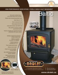
Columbia Installation and Operation Manual3.2.6 Judging Firewood Moisture ContentYou can find out if some firewood is dry enough to burn by using <strong>the</strong>se guidelines:• cracks form at <strong>the</strong> ends of logs as <strong>the</strong>y dry• as it dries in <strong>the</strong> sun, <strong>the</strong> wood turns from white or cream coloured to grey or yellow,• bang two pieces of wood toge<strong>the</strong>r; seasoned wood sounds hollow and wet woodsounds dull,• dry wood is much lighter in weight than wet wood,• split a piece, and if <strong>the</strong> fresh face feels warm and dry it is dry enough to burn; if it feelsdamp, it is too wet,• burn a piece; wet wood hisses and sizzles in <strong>the</strong> fire and dry wood does not.You could buy a wood moisture meter to test yourfirewood.3.3 Manufactured LogsDo not burn manufactured logs made of wax impregnated sawdust or logs with anychemical additives. Manufactured logs made of 100% compressed sawdust can beburned, but use caution in <strong>the</strong> number of <strong>the</strong>se logs burned at one time. Start with onemanufactured log and see how <strong>the</strong> stove reacts. You can increase <strong>the</strong> number of logsburned at a time to making sure <strong>the</strong> temperature never rises higher than 475 °F (246 °C)on a magnetic <strong>the</strong>rmometer for installation on single wall stove pipes or 900 °F (482 °C) ona probe <strong>the</strong>rmometer for installation on double wall stove pipe. The <strong>the</strong>rmometer shouldbe placed about 18” (457 mm) above <strong>the</strong> stove. Higher temperatures can lead to overheatand damage your stove.14
Columbia Installation and Operation ManualDO NOT LEAVE THE STOVE UNATTENDED WHEN THE DOOR IS SLIGHTLYOPENED DURING IGNITION. ALWAYS CLOSE THE DOOR AFTER IGNITION.After <strong>the</strong> kindling fire has mostly burned, you can add standard firewood pieces until youhave a fire of <strong>the</strong> right size for <strong>the</strong> conditions.4.2.2 The Top Down FireThe top down fire starting method solves two problems with <strong>the</strong> conventional method: first,it does not collapse and smo<strong>the</strong>r itself as it burns; and second, it is not necessary to buildup <strong>the</strong> fire gradually because <strong>the</strong> firebox is loaded before <strong>the</strong> fire is lit. A top down fire canprovide up to two hours of heating or more. The top down method only works properly if<strong>the</strong> wood is well-seasoned.Start by placing three or four full-sized split pieces of dry firewood in <strong>the</strong> firebox. Next,place 4 or 5 more finely split pieces of firewood (2” to 3” [50 mm to 75 mm] in dia.) on <strong>the</strong>base logs at right angles (log cabin style). Now place about 10 pieces of finely split kindlingon <strong>the</strong> second layer at right angles.The fire is topped with about 5 sheets of newspaper. You can just bunch <strong>the</strong>m up and stuff<strong>the</strong>m in between <strong>the</strong> kindling and <strong>the</strong> underside of <strong>the</strong> baffle. Or you can make newspaperknots by rolling up single sheets corner to corner and tying a knot in <strong>the</strong>m. The advantageof knots is that <strong>the</strong>y don’t roll off <strong>the</strong> fire as <strong>the</strong>y burn. Light <strong>the</strong> newspaper and watch as<strong>the</strong> fire burns from top to bottom.4.2.3 Two Parallel LogsPlace two spit logs in <strong>the</strong> firebox. Place a few sheets of twisted newspaper between <strong>the</strong>logs. Now place some fine kindling across <strong>the</strong> two logs and some larger kindling acrossthose, log cabin style. Light <strong>the</strong> newspaper.4.2.4 Using Fire StartersMany people like to use commercial fire starters instead of newspaper. Some of <strong>the</strong>sestarters are made of sawdust and wax and o<strong>the</strong>rs are specialized flammable solidchemicals. Follow <strong>the</strong> package directions for use.Gel starter may be used but only if <strong>the</strong>re are no hot embers present. Use only in a coldfirebox to start a fire.DO NOT USE FLAMMABLE LIQUIDS SUCH AS GASOLINE, NAPHTHA, FUEL OIL,MOTOR OIL, OR AEROSOLS TO START OR REKINDLE THE FIRE.16
Columbia Installation and Operation Manual4.3 Maintaining Wood Fires4.3.1 General AdviceWood heating with a space heater is very different than o<strong>the</strong>r forms of heating. There willbe variations in <strong>the</strong> temperature in different parts of <strong>the</strong> house and <strong>the</strong>re will be variationsin temperature throughout <strong>the</strong> day and night. This is normal, and for experienced woodburners <strong>the</strong>se are advantages of zone heating with wood.Do not expect steady heat output from your stove. It is normal for its surface temperatureto rise after a new load of wood is ignited and for its temperature to gradually decline as<strong>the</strong> fire progresses. This rising and falling of temperature can be matched to yourhousehold routines. For example, <strong>the</strong> area temperature can be cooler when you are active,such as when doing housework or cooking, and it can be warmer when you are inactive,such as when reading or watching television.Wood burns best in cycles. A cycle starts when a new load of wood is ignited by hot coalsand ends when that load has been consumed down to a bed of charcoal about <strong>the</strong> samesize as it was when <strong>the</strong> wood was loaded. Do not attempt to produce a steady heat outputby placing a single log on <strong>the</strong> fire at regular intervals. Always place at least three, andpreferably more, pieces on <strong>the</strong> fire at a time so that <strong>the</strong> heat radiated from one piece helpsto ignite <strong>the</strong> pieces next to it. Each load of wood should provide several hours of heating.The size of each load can be matched to <strong>the</strong> amount of heat needed.When you burn in cycles, you rarely need to open <strong>the</strong> stove’s loading door while <strong>the</strong> woodis flaming. This is an advantage because <strong>the</strong>re is more chance that smoke will leak from<strong>the</strong> stove when <strong>the</strong> door is opened as a full fire is burning. This is especially true if <strong>the</strong>chimney connector has 90 degree elbows and if <strong>the</strong> chimney runs up <strong>the</strong> outside wall of<strong>the</strong> house.IF YOU MUST OPEN THE DOOR WHILE THE FUEL IS FLAMING, OPEN THE AIRCONTROL FULLY FOR A FEW MINUTES, THEN UNLATCH AND OPEN THE DOORSLOWLY.4.3.2 Ash RemovalAsh should be removed from <strong>the</strong> firebox every two or three days of full time heating. Donot let <strong>the</strong> ash build up in <strong>the</strong> firebox because it will interfere with proper fire management.The best time to remove ash is after an overnight fire when <strong>the</strong> stove is relatively cool, but<strong>the</strong>re is still some chimney draft to draw <strong>the</strong> ash dust into <strong>the</strong> stove and prevent it fromcoming into <strong>the</strong> room.After ashes have been removed from <strong>the</strong> stove and placed in a tightly covered metalcontainer, <strong>the</strong>y should be taken outside immediately. The closed container of ashes shouldbe placed on a non-combustible floor or on <strong>the</strong> ground well away from all combustiblematerials pending final disposal. Ashes normally contain some live charcoal that can stayhot for several days. If <strong>the</strong> ashes are disposed of by burial in soil or o<strong>the</strong>rwise locally17
Columbia Installation and Operation Manualdispersed, <strong>the</strong>y should be retained in <strong>the</strong> closed container until all cinders have thoroughlycooled. O<strong>the</strong>r waste shall not be placed in this container.NEVER STORE ASHES INDOORS OR IN A NON-METALIC CONTAINER OR ON AWOODEN DECK.4.3.3 Raking CharcoalRekindle <strong>the</strong> fire when you notice that <strong>the</strong> room temperature has fallen. You will find mostof <strong>the</strong> remaining charcoal at <strong>the</strong> back of <strong>the</strong> firebox, fur<strong>the</strong>st from <strong>the</strong> door. Rake <strong>the</strong>secoals towards <strong>the</strong> door before loading. There are two reasons for this raking of <strong>the</strong> coals.First, it concentrates <strong>the</strong>m near where most of <strong>the</strong> combustion air enters <strong>the</strong> firebox andwhere <strong>the</strong>y can ignite <strong>the</strong> new load quickly, and second, <strong>the</strong> charcoal will not be smo<strong>the</strong>redby <strong>the</strong> new load of wood. If you were to simply spread <strong>the</strong> charcoal out, <strong>the</strong> new load willsmoulder for a long time before igniting.Remove ash first, and <strong>the</strong>n rake charcoal towards <strong>the</strong> front of <strong>the</strong> firebox before loading sothat it will ignite <strong>the</strong> new load.4.3.4 Firing Each New Load HotPlace <strong>the</strong> new load of wood on and behind <strong>the</strong> charcoal, and not too close to <strong>the</strong> glass.Close <strong>the</strong> door and open <strong>the</strong> air control fully. Leave <strong>the</strong> air control fully open until <strong>the</strong>firebox is full of flames, <strong>the</strong> wood has charred to black and its edges are glowing red. Firingeach load of wood hot accomplishes a few things:• drives <strong>the</strong> surface moisture from <strong>the</strong> wood,• creates a layer of char on <strong>the</strong> wood, which slows down its release of smoke,• heats <strong>the</strong> firebox components so <strong>the</strong>y reflect heat back to <strong>the</strong> fire, and• heats <strong>the</strong> chimney so it can produce strong, steady draft for <strong>the</strong> rest of <strong>the</strong> cycle.Although it is important to fire each new load hot to prepare for a clean burn, do not allow<strong>the</strong> fire to burn at full intensity for more than a few minutes.DO NOT LEAVE THE STOVE UNATTENDED WHILE A NEW LOAD IS BEING FIREDHOT.DO NOT OVERFIRE.18
Columbia Installation and Operation ManualWhen you burn a new load of wood hot to heat up <strong>the</strong> wood, <strong>the</strong> stove and <strong>the</strong> chimney,<strong>the</strong> result will be a surge of heat from <strong>the</strong> stove. This heat surge is welcome when <strong>the</strong>room temperature is a little lower than desirable, but not welcome if <strong>the</strong> space is alreadywarm. Therefore, allow each load of wood to burn down so that <strong>the</strong> space begins to cooloff a little before loading. Letting <strong>the</strong> space cool before loading is one of <strong>the</strong> secrets toclean burning and effective zone heating.4.3.5 Turning Down <strong>the</strong> Air SupplyOnce <strong>the</strong> firewood, firebox and chimney are hot, you can begin to reduce <strong>the</strong> air supply fora steady burn.As you reduce <strong>the</strong> air supply to <strong>the</strong> fire, two important things happen. First, <strong>the</strong> firing rateslows down to spread <strong>the</strong> heat energy in <strong>the</strong> fuel over a longer period of time. Second, <strong>the</strong>flow rate of exhaust through <strong>the</strong> stove and flue pipe slows down, which gives more time for<strong>the</strong> transfer of heat from <strong>the</strong> exhaust. You will notice that as you reduce <strong>the</strong> air setting, <strong>the</strong>flames slow down. This is your indication that <strong>the</strong> stove is burning at its peak efficiency.If <strong>the</strong> flames get small and almost disappear when you turn down <strong>the</strong> air, you have turneddown <strong>the</strong> air too early, or your firewood is wetter than it should be. With good fuel andcorrect air control use, <strong>the</strong> flames should slow down, but should stay large and steady,even as <strong>the</strong> air supply is reduced.4.3.6 Building Different Fires for Different NeedsUsing <strong>the</strong> air control is not <strong>the</strong> only way to match <strong>the</strong> stove’s heat output to <strong>the</strong> heatdemand. Your house will need far less heat in October than in January to be kept at acomfortable temperature. If you fill <strong>the</strong> firebox full in fall wea<strong>the</strong>r, you will ei<strong>the</strong>r overheat<strong>the</strong> space or turn <strong>the</strong> stove down so much that <strong>the</strong> fire will be smoky and inefficient. Hereare some suggestions for building fires to match different heat demand.19
Columbia Installation and Operation Manual4.3.6.1 Small Fires to Take <strong>the</strong> Chill Off <strong>the</strong> HouseTo build a small fire that will produce a low heat output, use small pieces of firewood andload <strong>the</strong>m crisscross in <strong>the</strong> firebox. The pieces should be only 3” to 4” in diameter. Afterraking <strong>the</strong> coals, you can lay two pieces parallel to each o<strong>the</strong>r corner to corner in <strong>the</strong>firebox and lay two more across <strong>the</strong>m in <strong>the</strong> o<strong>the</strong>r direction. Open <strong>the</strong> air control fully andonly reduce <strong>the</strong> air after <strong>the</strong> wood is fully flaming. This kind of fire is good for mild wea<strong>the</strong>rwhen you are around to tend <strong>the</strong> stove and should provide enough heat for four hours ormore. Small fires like this are a good time to use softer wood species so <strong>the</strong>re will be lesschance of overheating <strong>the</strong> house.4.3.6.2 Long Lasting Low Output FiresSometimes you will want to build a fire to last up to eight hours, but don’t need intenseheat. In this case use soft wood species and place <strong>the</strong> logs compactly in <strong>the</strong> firebox so <strong>the</strong>pieces are packed tightly toge<strong>the</strong>r. You will need to fire <strong>the</strong> load hot for long enough to fullychar <strong>the</strong> log surfaces before you can turn <strong>the</strong> air down. Make sure <strong>the</strong> fire is flamingbrightly before leaving <strong>the</strong> fire to burn.4.3.6.3 High Output Fires for Cold Wea<strong>the</strong>rWhen <strong>the</strong> heat demand is high during cold wea<strong>the</strong>r, you’ll need a fire that burns steadilyand brightly. This is <strong>the</strong> time to use your biggest pieces of hardwood fuel if you have it. Put<strong>the</strong> biggest pieces at <strong>the</strong> back of <strong>the</strong> firebox and place <strong>the</strong> rest of <strong>the</strong> pieces compactly. Adensely built fire like this will produce <strong>the</strong> longest burn your stove is capable of.You will need to be cautious when building fires like this because if <strong>the</strong> air is turned downtoo much, <strong>the</strong> fire could smoulder. Make sure <strong>the</strong> wood is flaming brightly before leaving<strong>the</strong> fire to burn.4.3.6.4 Maximum Burn Cycle TimesThe burn cycle time is <strong>the</strong> period between loading wood on a coal bed and <strong>the</strong>consumption of that wood back to a coal bed of <strong>the</strong> same size. The flaming phase of <strong>the</strong>fire lasts for roughly <strong>the</strong> first half of <strong>the</strong> burn cycle and <strong>the</strong> second half is <strong>the</strong> coal bedphase during which <strong>the</strong>re is little or no flame. The length of burn you can expect from yourstove, including both <strong>the</strong> flaming and coal bed phases, will be affected by a number ofthings, such as:• firebox size,• <strong>the</strong> amount of wood loaded,• <strong>the</strong> species of wood you burn,• <strong>the</strong> wood moisture content,• <strong>the</strong> size of <strong>the</strong> space to be heated,• <strong>the</strong> climate zone you live in, and• <strong>the</strong> time of year.20
Columbia Installation and Operation ManualThe table below provides a very general indication of <strong>the</strong> maximum burn cycle times youare likely to experience, based on firebox volume.FIREBOX VOLUMEMAXIMUMBURN TIME3.0 c.f. 9 to 10 hoursLong burn times are not necessarily an indication of efficient stove operation. When youare home during <strong>the</strong> day and able to tend <strong>the</strong> fire, it is preferable to build a smaller fire thatmight provide three or four hours of heating than to fully load <strong>the</strong> firebox for a much longerburn. Shorter burn cycles make it easier to match <strong>the</strong> heat output of <strong>the</strong> stove to <strong>the</strong> heatdemand of <strong>the</strong> space.4.3.6.5 North-South Fires Versus East-West FiresIn fireboxes that are roughly square, wood can be loaded so that looking through <strong>the</strong> glassdoor you see <strong>the</strong> ends of <strong>the</strong> logs (north-south) or <strong>the</strong> sides of <strong>the</strong> logs (east-west).East-west loads that are built compactly break down slowly when heated, but <strong>the</strong> amountof wood you can load is limited because if you put in too many pieces, one may fall against<strong>the</strong> glass. East-west loads are excellent for long, low output fires for relatively mildwea<strong>the</strong>r.North-south loads break down more quickly, but much more wood can be loaded at a time.This makes north-south loading good for high output, long lasting fires for cold wea<strong>the</strong>r.21
Columbia Installation and Operation Manual5 Maintaining Your Wood Heating System5.1 Stove MaintenanceYour new stove will give many years of reliable service if you use and maintain it correctly.Some of <strong>the</strong> internal components of <strong>the</strong> firebox, such as firebricks, baffles and air tubes,will wear over time under intense heat. You should always replace defective parts withoriginal parts (see Appendix 4: Exploded Diagram and Parts List). For firing each loadhot to begin a cycle as described above will not cause premature deterioration of <strong>the</strong>stove. However, letting <strong>the</strong> stove run with <strong>the</strong> air control fully open for entire cycles cancause damage over time. The hotter you run <strong>the</strong> stove throughout burn cycles, <strong>the</strong> morequickly its components will deteriorate. For that reason, never leave <strong>the</strong> stoveunattended while a new load is being fired hot.5.1.1 Cleaning Door GlassUnder normal conditions, your door glass should stay relatively clear. If your firewood isdry enough and you follow <strong>the</strong> operating instructions in this <strong>manual</strong>, a whitish, dustydeposit will form on <strong>the</strong> inside of <strong>the</strong> glass after a week or so of use. This is normal andcan be easily removed when <strong>the</strong> stove is cool by wiping with a damp cloth or paper toweland <strong>the</strong>n drying. Never try to clean <strong>the</strong> glass when <strong>the</strong> stove is hot.In spring and fall when <strong>the</strong> stove is run at lower temperatures, you may see some lightbrown stains forming, especially at <strong>the</strong> lower corners of <strong>the</strong> glass. This indicates that <strong>the</strong>fire has been smoky and some of <strong>the</strong> smoke has condensed on <strong>the</strong> glass. When <strong>the</strong>wea<strong>the</strong>r is mild, you may find that letting <strong>the</strong> fire go out is better than trying to maintain acontinuous fire. Use <strong>the</strong> technique described above for building a fire to take <strong>the</strong> chill off<strong>the</strong> house.If you do get brown stains on <strong>the</strong> glass you can remove <strong>the</strong>m with special cleaners forwood stove glass doors. Do not use abrasives to clean your stove’s door glass.The deposits that form on <strong>the</strong> glass are <strong>the</strong> best indication of <strong>the</strong> quality of your fuel andhow well you are doing in operating <strong>the</strong> stove. Your goal should be clear glass with nobrown stains. If you continue to see brown stains on <strong>the</strong> glass, something about your fueland operating procedure needs to be changed. Stains on <strong>the</strong> glass indicate incompletecombustion of <strong>the</strong> wood, which also means more smoke emissions and faster formation ofcreosote in <strong>the</strong> chimney.If you see brown streaks coming from <strong>the</strong> edge of <strong>the</strong> glass, it is time to replace <strong>the</strong> gasketaround <strong>the</strong> glass. Visit your stove retailer to get <strong>the</strong> self-adhesive glass gasket and follow<strong>the</strong> instructions below for installation.22
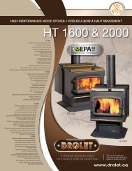
Columbia Installation and Operation Manual5.1.2 Door adjustmentIn order for your stove to burn at its best efficiency, <strong>the</strong> door must provide a perfect sealwith <strong>the</strong> firebox. Therefore, <strong>the</strong> gasket should be inspected periodically making sure toobtain an air tight fit. Airtightness can be improved with a simple latch mechanismadjustment. To adjust:1. Remove <strong>the</strong> lock pin (spring pin) by pulling and turning it using pliers ("wise grip").2. Turn <strong>the</strong> handle counter clock wise one turn to increase pressure.3. Re-install <strong>the</strong> lock pin (spring pin) with a small hammer.23
Columbia Installation and Operation Manual5.1.3 Replacing <strong>the</strong> Door GasketIt is important to maintain <strong>the</strong> gasket in good condition. After a year or more of use, <strong>the</strong>door gasket will compress and become hard, which may allow air to leak past it. You cantest <strong>the</strong> condition of <strong>the</strong> door gasket by closing and latching <strong>the</strong> door on a strip of paper.Test all around <strong>the</strong> door. If <strong>the</strong> paper slips out easily anywhere, it is time to replace <strong>the</strong>gasket.Use <strong>the</strong> correct replacement gasket that you can purchase from your retailer. The diameterand density of <strong>the</strong> gasket is important to getting a good seal.Place <strong>the</strong> door face-down on something soft like a cushion of rags or piece of carpet.Remove <strong>the</strong> old gasket from <strong>the</strong> door by pulling and prying it out with an old screw driver.Then use <strong>the</strong> screwdriver to scrape <strong>the</strong> old gasket adhesive from <strong>the</strong> door. Now run a 1/4”(6 mm) bead of high temperature silicone in <strong>the</strong> door gasket groove. Starting from <strong>the</strong>middle of <strong>the</strong> hinge side, press <strong>the</strong> gasket into <strong>the</strong> groove. Do not stretch <strong>the</strong> gasket asyou place it. Leave <strong>the</strong> gasket about 1/2” long when you cut it and press <strong>the</strong> end into <strong>the</strong>groove. Tuck any loose fibres under <strong>the</strong> gasket and into <strong>the</strong> silicone. Close <strong>the</strong> door anddo not use <strong>the</strong> stove for 24 hours.5.1.4 Replacing <strong>the</strong> Glass Gasket and/or <strong>the</strong> GlassIt is a good idea to replace <strong>the</strong> glass gasket when <strong>the</strong> door gasket is replaced. The gasketis flat, adhesive-backed, woven fibreglass. Remove <strong>the</strong> glass retaining screws (A) andboth metal frames (B) that holds <strong>the</strong> glass to <strong>the</strong> door frame. Lift out <strong>the</strong> glass (C) and pulloff <strong>the</strong> old gasket. This is a good time to clean <strong>the</strong> glass thoroughly.24
Columbia Installation and Operation ManualThe gasket must be centred on <strong>the</strong> edge of <strong>the</strong> glass. To do this easily, peel back asection of <strong>the</strong> paper covering <strong>the</strong> adhesive and place <strong>the</strong> gasket on a table with <strong>the</strong>adhesive side up. Stick <strong>the</strong> end of <strong>the</strong> gasket to <strong>the</strong> middle of one edge, <strong>the</strong>n press <strong>the</strong>edge of <strong>the</strong> glass down onto <strong>the</strong> gasket, taking care that it is perfectly centred on <strong>the</strong>gasket. Peel off more of <strong>the</strong> backing and rotate <strong>the</strong> glass and press <strong>the</strong> next section onto<strong>the</strong> gasket. Do not stretch <strong>the</strong> gasket as you place it. Continue until you get to <strong>the</strong> start andtrim <strong>the</strong> gasket to length. Now pinch <strong>the</strong> gasket to <strong>the</strong> glass in a U shape, all around <strong>the</strong>glass. Reinstall <strong>the</strong> glass, being careful to centre <strong>the</strong> glass carefully in <strong>the</strong> door. Do notover-tighten <strong>the</strong> screws. Note that <strong>the</strong> two main causes of broken door glass are unevenplacement in <strong>the</strong> door and over-tightening of retaining screws.Do not abuse <strong>the</strong> glass door by striking or slamming shut. Do not use <strong>the</strong> stove if <strong>the</strong> glassis broken. To change <strong>the</strong> glass, perform <strong>the</strong> same operation described above.5.1.5 Cleaning and Painting <strong>the</strong> StoveDo not attempt to clean or paint <strong>the</strong> stove when <strong>the</strong> unit is hot. Painted surfaces canbe wiped down with a damp cloth. Plated surfaces may be scratched by abrasive cleaners.To maintain <strong>the</strong> finish at its original brilliance, use only a damp soft cloth to clean platedsurfaces.If <strong>the</strong> paint becomes scratched or damaged, you can give your wood stove a brand newlook by repainting it with heat-resistant paint. Before painting, roughen <strong>the</strong> surface with finesand paper, wipe it down to remove dust, and apply two thin coats of paint. For bestresults, use <strong>the</strong> same paint that was originally used on <strong>the</strong> stove, which is available inspray cans. See your dealer for details.5.2 Chimney and Chimney Connector Maintenance5.2.1 Why Chimney Cleaning is NecessaryWood smoke can condense inside <strong>the</strong> chimney connector and chimney, forming acombustible deposit called creosote. If creosote is allowed to build up in <strong>the</strong> ventingsystem it can ignite when a hot fire is burned in <strong>the</strong> stove and a very hot fire can progressto <strong>the</strong> top of <strong>the</strong> chimney. Severe chimney fires can damage even <strong>the</strong> best chimneys.25
Columbia Installation and Operation ManualPART B - INSTALLATION6 Safety Information6.1 Summary of Installation Cautions and Warnings• THE INFORMATION GIVEN ON THE CERTIFICATION LABEL AFFIXED TO THEAPPLIANCE ALWAYS OVERRIDES THE INFORMATION PUBLISHED, IN ANYOTHER MEDIA (OWNER’S MANUAL, CATALOGUES, FLYERS, MAGAZINESAND/OR WEB SITES).• MIXING OF APPLIANCE COMPONENTS FROM DIFFERENT SOURCES ORMODIFYING COMPONENTS MAY RESULT IN HAZARDOUS CONDTIONS. WHEREANY SUCH CHANGES ARE PLANNED, STOVE BUILDER INTERNATIONAL INC.SHOULD BE CONTACTED IN ADVANCE.• ANY MODIFICATION OF THE APPLIANCE THAT HAS NOT BEEN APPROVED INWRITING BY THE TESTING AUTHORITY VIOLATES CSA B365 (CANADA), ANDANSI NFPA 211 (USA).• CONNECT THIS STOVE ONLY TO A LISTED FACTORY-BUILT CHIMNEY FORUSE WITH SOLID FUEL OR TO A LINED MASONRY CHIMNEY CONFORMING TONATIONAL AND LOCAL BUILDING CODES.• IF REQUIRED, A SUPPLY OF COMBUSTION AIR SHALL BE PROVIDED TO THEROOM OR SPACE.• DO NOT CONNECT TO OR USE IN CONJUNCTION WITH ANY AIR DISTRIBUTIONDUCTWORK UNLESS SPECIFICALLY APPROVED FOR SUCH INSTALLATION.• DO NOT CONNECT THIS UNIT TO A CHIMNEY FLUE SERVING ANOTHERAPPLIANCE.• MAY BE INSTALLED IN A MOBILE HOME.• THIS MOBILE HOME APPROVED STOVE REQUIRES INSTALLATION OF AFRESH AIR KIT, SOLD SEPARATELY.WARNING: DO NOT INSTALL IN SLEEPING ROOM.WARNING: THE STOVE MUST BE ATTACHED TO THE STRUCTURE OF THEMOBILE HOME.CAUTION: THE STRUCTURAL INTEGRITY OF THE MOBILE HOME FLOOR, WALL,AND CEILING/ROOF MUST BE MAINTAINED.27
Columbia Installation and Operation Manual6.2 Regulations Covering Stove InstallationWhen installed and operated as described in <strong>the</strong>se instructions, <strong>the</strong> Columbia wood stoveis suitable for use as a freestanding heater in residential installations. The Columbia woodstove is not intended for installation in a sleeping room of a mobile home.In Canada, <strong>the</strong> CSA B365 Installation Code for Solid Fuel Burning Appliances andEquipment and <strong>the</strong> CSA C22.1 Canadian National Electrical Code are to be followed in <strong>the</strong>absence of local code requirements. In <strong>the</strong> USA, <strong>the</strong> ANSI NFPA 211 Standard forChimneys, Fireplaces, Vents and Solid Fuel-Burning Appliances and <strong>the</strong> ANSI NFPA 70National Electrical Code are to be followed in <strong>the</strong> absence of local code requirements.This stove must be connected to a chimney complying with <strong>the</strong> requirements for Type HTchimneys in <strong>the</strong> Standard for Factory-Built Chimneys for Residential Type and BuildingHeating Appliances, UL 103 HT and ULC S629 or to a code-approved masonry chimneywith a flue liner.28
Columbia Installation and Operation Manual7 Clearances to Combustible MaterialThe clearances shown in this section have been determined by test according toprocedures set out in safety standards ULC S627 (Canada) and UL1482 (U.S.A.). When<strong>the</strong> stove is installed so that its surfaces are at or beyond <strong>the</strong> minimum clearancesspecified, combustible surfaces will not overheat under normal and even abnormaloperating conditions.No part of <strong>the</strong> stove or flue pipe may be located closer to combustibles than <strong>the</strong>minimum clearance figures given.7.1 Location of <strong>the</strong> certification labelSince <strong>the</strong> information given on <strong>the</strong> certification label affixed to <strong>the</strong> appliance alwaysoverrides <strong>the</strong> information published, in any o<strong>the</strong>r media (owner’s <strong>manual</strong>, catalogues,flyers, magazines and/or web sites) it is important to refer to it in order to have a safe andcompliant installation. In addition, you will find information about your stove (model, serialnumber, etc.). You can find <strong>the</strong> certification label on <strong>the</strong> back of <strong>the</strong> stove.7.2 Clearances to Walls and CeilingThe clearances to combustible walls may be slightly different in Canada and <strong>the</strong> U.S.A.and may also differ depending on whe<strong>the</strong>r you use single or double wall flue pipe. Pleasebe sure to choose <strong>the</strong> correct clearance for your location and type of flue pipe. See figureClearances to combustible materials and floor protection to match each letter to aclearance.29
Columbia Installation and Operation ManualCLEARANCES(SINGLE WALL PIPE)CANADAUSAA 14½" (368 mm) 14" (356 mm)B 12" (305 mm) 12" (305 mm)C 8¼" (210 mm) 7" (178 mm)D 18" (457 mm) 17¾" (451 mm)E 22" (559 mm) 22" (559 mm)F 18" (457 mm) 17" (432 mm)K 48" (1219 mm) 48" (1219 mm)L 84" (213 cm) 84" (213 cm)CLEARANCES(DOUBLE WALL PIPE)CANADAUSAA 6" (152 mm) 6" (152 mm)B 11" (279 mm) 11" (279 mm)C 5" (127 mm) 5" (127 mm)D 9¾" (248 mm) 9¾" (248 mm)E 21" (533 mm) 21" (533 mm)F 15" (381 mm) 15" (381 mm)K 48" (1219 mm) 48" (1219 mm)L 84" (213 cm) 84" (213 cm)Clearances for mobile homesMOBILE HOME CLEARANCES (DOUBLE WALLPIPE)CANADAUSAA 6" (152 mm) 6" (152 mm)B 11" (279 mm) 11" (279 mm)C 5" (127 mm) 5" (127 mm)D 9¾" (248 mm) 9¾" (248 mm)E 21" (533 mm) 21" (533 mm)F 15" (381 mm) 15" (381 mm)K 48" (1219 mm) 48" (1219 mm)L 84" (213 cm) 84" (213 cm)Important Note: Addition required to <strong>the</strong> stove when it is installed in a mobile home.See Appendix 1 for details.30
Columbia Installation and Operation ManualClearances to combustible materials and floor protection31
Columbia Installation and Operation Manual7.3 Floor protectorIf <strong>the</strong> stove is to be installed on top of a combustible floor, it must be guarded by a noncombustible material as shown on figure above (see <strong>the</strong> dotted line area).CANADAFLOOR PROTECTOR*USAG 8’’ (203 mm) – Note 1 N/A (Canada only)H 8’’ (203 mm) N/A (Canada only)I 18’’ (457 mm)From door opening16’’ (406 mm)From door openingJ N/A (USA only) 8’’ (203 mm)M 8’’ (203 mm) N/A (Canada only)N N/A (USA only) Note 2*Steel with a minimum thickness of 0.015’’ (0.38 mm) or ceramic tiles sealed toge<strong>the</strong>rwith grout. No protection is required if <strong>the</strong> unit is installed on a non-combustible floor(ex: concrete).Note 1: The floor protection at <strong>the</strong> back of <strong>the</strong> stove is limited to <strong>the</strong> stove’s requiredclearance if such clearance is smaller than 8 inches (203 mm).Note 2: Only required under <strong>the</strong> horizontal section of <strong>the</strong> connector. Must exceed eachside of <strong>the</strong> connector by at least 2 inches (51 mm).32
Columbia Installation and Operation Manual7.4 Reducing Wall and Ceiling Clearances SafelyIt is often desirable to reduce<strong>the</strong> minimum installationclearances by placing <strong>the</strong> stovecloser to walls so <strong>the</strong> installationtakes up less floor space. Youcan safely reduce <strong>the</strong> minimumclearances by permanentlyinstalling a shield between <strong>the</strong>stove and combustible material.The rules for safe shields can becomplicated, so read <strong>the</strong>mcarefully and follow <strong>the</strong>mexactly. Note that <strong>the</strong>re may beminor regional differences inclearance reduction rules so besure to check with your buildingor fire inspector beforeproceeding.7.4.1 Shield Construction Rules1. Minimum space behind shield: 25 mm (1 in.). In Canada 21 mm (7/8 in).2. Minimum clearance along <strong>the</strong> bottom of shield: 25 mm (1 in.).3. Maximum clearance along <strong>the</strong> bottom of shield: 75 mm (3 in.).4. Minimum clearance along <strong>the</strong> top of shield at ceiling: 75 mm (3 in.).5. Shield extension beyond each side of appliance: 450 mm (18 in.).6. Shield extension above appliance: 500 mm (20 in.).7. Edge clearance for ceiling shields: 75 mm (3 in.).8. Adhesives used in shield construction must not ignite or lose adhesive qualities attemperatures likely to be encountered.9. Mounting hardware must allow full vertical ventilation.10. Mounting hardware must not be located closer than 200 mm (8 in.) from <strong>the</strong> verticalcentre line of <strong>the</strong> appliance.11. Mounting hardware which extends from <strong>the</strong> shield surface into combustibles may beused only at <strong>the</strong> edges of <strong>the</strong> shield.33
Columbia Installation and Operation Manual7.4.2 Table of Clearance Reduction PercentagesType of shieldSheet metal, a minimum of 24gauge (0.61 mm) in thickness ,spaced out at least 25 mm (1 in)*by non-combustible spacersClearances may bereduced by <strong>the</strong>sepercentagesSidesand rear %Top %(ceiling)67 50Ceramic tiles, or equivalent noncombustiblematerial, on noncombustibleboard spaced out atleast 25 mm (1 in)* by noncombustiblespacersCeramic tiles, or equivalent noncombustiblematerial, on noncombustibleboard, with aminimum of 24 gauge (0.61 mm)sheet metal backing spaced out atleast 25 mm (1 in)* by noncombustiblespacersBrick, spaced out at least 25 mm(1 in)* by non-combustible spacers50 3367 5050 N/ABrick, with a minimum of 24 gauge(0.61 mm) sheet metal backing,spaced out at least 25 mm (1 in)*by non-combustible spacers67 N/A* In Canada this space can be 21 mm (7/8 in)34
Columbia Installation and Operation Manual8 The Venting System8.1 GeneralThe venting system, made up of <strong>the</strong> chimney and <strong>the</strong> connecting pipe between <strong>the</strong> stoveand <strong>the</strong> chimney, acts as <strong>the</strong> engine that drives your wood heating system. Even <strong>the</strong> beststove will not function safely and efficiently as intended if it is not connected to a suitablechimney.The heat in <strong>the</strong> flue gases that pass from <strong>the</strong> stove and chimney connector into <strong>the</strong>chimney is not waste heat. This heat is what <strong>the</strong> chimney uses to make <strong>the</strong> draft thatdraws in combustion air, keeps smoke inside <strong>the</strong> stove and safely vents exhaust tooutside. You can think of heat in <strong>the</strong> flue gas as <strong>the</strong> fuel <strong>the</strong> chimney uses to make draft.8.2 Suitable ChimneysYour wood stove will provide optimum efficiency and performance when connected to a 6-inch diameter chimney flue system. The connection to a chimney having a diameter of atleast 5 inches (Canada only) or no more than 7 inches is permitted, if it allows <strong>the</strong> properventing of combustion gases and that such application is verified and authorized by aqualified installer. O<strong>the</strong>rwise, <strong>the</strong> diameter of <strong>the</strong> flue should be 6 inches.To be suitable, a factory-built metalchimney must comply with UL 103 HT(U.S.A.) or ULC S629 (Canada).8.2.1 Factory-built Metal ChimneysThese are sometimes referred to as ‘hightemp’ chimneys because <strong>the</strong>y have <strong>the</strong>special characteristics to withstand <strong>the</strong>temperatures that can be created bywood burning stoves. Factory-builtchimneys are tested as a system with all<strong>the</strong> necessary components forinstallation. The instructions provided with<strong>the</strong> chimney by its manufacturer are <strong>the</strong>only reliable source of installationguidelines. To be safe and effective, <strong>the</strong>chimney must be installed exactly inaccordance with <strong>the</strong> manufacturer’sinstructions. Use only componentsintended for <strong>the</strong> brand and model ofchimney you are using. Neversubstitute parts from o<strong>the</strong>r chimneybrands or fabricate your owncomponents. The chimney must be atype suitable for solid fuel.35
Columbia Installation and Operation Manual8.2.2 Factory-built Metal Chimneys inmobile homesFor use in a mobile home, this stove is tobe connected to a 6” in diameter doublewall factory built chimney conforming toCAN/UCL-S629, Standards for 650°CFactory-built chimney. The total length of<strong>the</strong> flue system should be at least 12 feetincluding elbows, from <strong>the</strong> top of <strong>the</strong>stove.To maintain an effective vapour barrier,insulation and waterproof at <strong>the</strong> chimneyand outside flue pipe, install a mobilehome roof flashing and seal it withsilicone.36
Columbia Installation and Operation Manual8.2.3 Masonry ChimneysThe stove may also be connected to amasonry chimney, provided <strong>the</strong>chimney complies with <strong>the</strong> constructionrules found in <strong>the</strong> building codeenforced locally. The chimney musthave ei<strong>the</strong>r a clay liner or a suitablylisted stainless steel liner. If <strong>the</strong>masonry chimney has a square orrectangular liner that is larger in crosssectional area than a round 6” flue, itshould be relined with a suitably listed6” stainless steel liner. Do notdownsize <strong>the</strong> flue to less than 6” unless<strong>the</strong> venting system is straight andexceeds 25 feet in height. Whenpassing through a combustible wall, <strong>the</strong>use of an insulated listed thimble isrequired.8.3 Minimum Chimney HeightThe top of <strong>the</strong> chimney should betall enough to be above <strong>the</strong> airturbulence caused when windblows against <strong>the</strong> house and itsroof. The chimney must extend atleast 1 m (3 ft.) above <strong>the</strong> highestpoint of contact with <strong>the</strong> roof, andat least 60 cm (2 ft.) higher thanany roof line or obstacle within ahorizontal distance of 3 m (10 ft.).37
Columbia Installation and Operation Manual8.4 The Relationship Between <strong>the</strong> Chimney and <strong>the</strong> HouseBecause <strong>the</strong> venting system is <strong>the</strong> engine that drives <strong>the</strong> wood heating system, it musthave <strong>the</strong> right characteristics. The signs of bad system design are cold backdrafting when<strong>the</strong>re is no fire in <strong>the</strong> stove, slow kindling of new fires, and smoke roll-out when <strong>the</strong> door isopened for loading. There are two guidelines to follow. First, <strong>the</strong> chimney should beinstalled up through <strong>the</strong> heated space of <strong>the</strong> house, not out and up an outside wall.Second, <strong>the</strong> chimney should penetrate <strong>the</strong> top of <strong>the</strong> building at or near <strong>the</strong> highest heatedspace.8.4.1 Why inside chimneys are preferredVenting systems that rise straight up from <strong>the</strong> stove flue collar provide <strong>the</strong> bestperformance. Chimneys that rise inside <strong>the</strong> warm space of <strong>the</strong> house tend to provide asmall amount of draft even when <strong>the</strong>re is no fire burning. This means that when you light afire, <strong>the</strong> initial smoke goes up <strong>the</strong> chimney and strong draft builds quickly as <strong>the</strong> chimneyflue warms up. Although <strong>the</strong>y are common in North America, chimneys that exit a housewall and run up outside can cause problems.Good System DesignInside chimneys are preferred because evenwhen no fire is burning, <strong>the</strong>re is normallyupward flow in <strong>the</strong> system.Inferior System DesignOutside chimneys are a problembecause when no fire burns <strong>the</strong>y will gointo cold backdraft if <strong>the</strong> stove isinstalled low in <strong>the</strong> house.38
Columbia Installation and Operation Manual8.4.2 Why <strong>the</strong> chimney should penetrate <strong>the</strong> highest heated spaceWhen it is cold outside, <strong>the</strong> warm air in <strong>the</strong> house is buoyant so it tends to rise. Thistendency of warm air to rise creates a slight pressure difference in <strong>the</strong> house. Called ‘stackeffect’, it produces a slightly negative pressure low in <strong>the</strong> house (relative to outside) and aslightly positive pressure zone high in <strong>the</strong> house. If <strong>the</strong>re is no fire burning in a heaterconnected to a chimney that is shorter than <strong>the</strong> warm space inside <strong>the</strong> house, <strong>the</strong> slightnegative pressure low in <strong>the</strong> house will compete against <strong>the</strong> desired upward flow in <strong>the</strong>chimney.There are two reasons why <strong>the</strong>chimney in <strong>the</strong> house at right willcold backdraft when it is coldoutside and <strong>the</strong>re is no fireburning in <strong>the</strong> stove. First, <strong>the</strong>chimney runs up <strong>the</strong> outside of <strong>the</strong>house, so <strong>the</strong> air in it is colder anddenser than <strong>the</strong> warm air in <strong>the</strong>house. And second, <strong>the</strong> chimneyis shorter than <strong>the</strong> heated spaceof <strong>the</strong> house, meaning <strong>the</strong>negative pressure low in <strong>the</strong>house will pull outside air down<strong>the</strong> chimney, through <strong>the</strong> stoveand into <strong>the</strong> room. Even <strong>the</strong> fineststove will not work well whenconnected to this chimney.8.5 Supply of Combustion AirIn Canada, wood stoves are not required to have a supply of combustion air from outdoors(except in mobile homes) because research has shown that <strong>the</strong>se supplies do not giveprotection against house depressurization and may fail to supply combustion air duringwindy wea<strong>the</strong>r. However, to protect against <strong>the</strong> risk of smoke spillage due to housedepressurization, a carbon monoxide (CO) detector/alarm is required in <strong>the</strong> room inwhich <strong>the</strong> stove is installed. The CO detector will provide warning if for any reason <strong>the</strong>wood stove fails to function correctly.39
Columbia Installation and Operation Manual8.5.1 Combustion Air Supply in Mobile HomesOnly a wood stove certified and labelled as ‘mobile home approved’ may beinstalled in a mobile home. The Columbia stove is ‘mobile home approved’. Wood stovesinstalled in mobile homes must have a ducted supply of combustion air from outdoors. Thisair supply should be routed down through <strong>the</strong> house floor into <strong>the</strong> vented crawl spaceunder <strong>the</strong> mobile home. The air supply duct should be non-combustible aluminum flex ductwith a screened wea<strong>the</strong>rhood on <strong>the</strong> outside end.Note: Fabric duct may also be used, provided it is suitable for HVAC use and meets <strong>the</strong>requirements of ULC-S110 or UL-181 Class 1 standards. It must have a non-combustibleinsulation and be corrosion resistant.Where a mobile home has been converted to a standard house by mounting it on apermanent basement foundation, <strong>the</strong> supply of outdoor air is not required.8.5.2 Air Supply in Conventional HousesThe safest and most reliable supply of combustion air for your wood stove is from <strong>the</strong> roomin which it is installed. Room air is already preheated so it will not chill <strong>the</strong> fire, and itsavailability is not affected by wind pressures on <strong>the</strong> house. Contrary to commonlyexpressed concerns, almost all tightly-sealed new houses have enough natural leakage toprovide <strong>the</strong> small amount of air needed by <strong>the</strong> stove. The only case in which <strong>the</strong> woodstove may not have adequate access to combustion air is if <strong>the</strong> operation of a powerfulexhaust device (such as a kitchen range exhaust) causes <strong>the</strong> pressure in <strong>the</strong> house tobecome negative relative to outdoors.Some jurisdictions in <strong>the</strong> United States require that wood stoves have a supply ofcombustion air from outdoors. If you do install an air supply through <strong>the</strong> wall of <strong>the</strong> house,be aware that its pressure can be affected during windy wea<strong>the</strong>r. If you notice changes inwood stove performance in windy wea<strong>the</strong>r, and in particular if smoke puffs from <strong>the</strong> stove,you should disconnect <strong>the</strong> outdoor air duct from <strong>the</strong> stove and remove <strong>the</strong> duct. In somewindy conditions, negative pressure at <strong>the</strong> duct wea<strong>the</strong>rhood outside <strong>the</strong> house wall maydraw hot exhaust gases from <strong>the</strong> stove backwards through <strong>the</strong> duct to outdoors. Check <strong>the</strong>outdoor air duct for soot deposits when <strong>the</strong> full system is cleaned and inspected at leastonce each year.8.6 Installing <strong>the</strong> Chimney ConnectorThe chimney connector is <strong>the</strong> single or double wall pipe installed between <strong>the</strong> stove fluecollar and <strong>the</strong> chimney breech. Single wall pipe components are available from mosthardware and building supply stores. These components are not usually tested to aparticular standard and certified as compliant. Therefore, a list of rules found in solid fuelinstallation codes apply to <strong>the</strong> installation of single wall pipe.Double wall chimney connectors are tested and certified. The rules for double wall pipe arefound in <strong>the</strong> manufacturer’s installation instructions. These rules will be very different thanthose for single wall.40
Columbia Installation and Operation Manual8.6.1 Installation of Single Wall Chimney ConnectorThe chimney connector assembly has been called ‘<strong>the</strong> weak link’ in <strong>the</strong> safety of woodheating systems because failure to install <strong>the</strong> connector properly (which has been commonin <strong>the</strong> past) can result in house fires.The best flue pipe assembly is one that rises straight up from <strong>the</strong> stove to <strong>the</strong> base of <strong>the</strong>chimney with no elbows. Straight assemblies are less likely to cause problems like smokeroll-out when <strong>the</strong> door is opened for loading. They are also more stable and easier tomaintain than assemblies with elbows. Horizontal runs of flue pipe should be avoidedwhere possible because <strong>the</strong>y reduce chimney draft.Use 45 degree elbows where possible, instead of 90 degree elbows.41
Columbia Installation and Operation ManualThe rules below are based on those found in <strong>the</strong> CSA B365 installation code. Pleasecarefully follow <strong>the</strong>se installation instruction rules, or those enforced where you live.• Maximum overall length of straight pipe: 3 m (10 ft.) including elbows.• Minimum clearance from combustible material: 450 mm (18 in.). The minimumclearance may be reduced by 50 percent to 225 mm (9 in.) if suitable shielding isinstalled ei<strong>the</strong>r on <strong>the</strong> pipe or on <strong>the</strong> combustible surface.• The assembly should be as short and direct as possible between <strong>the</strong> stove andchimney. The use of two 45 degree elbows is often preferable to a single 90 degreeelbow because less turbulence is created in <strong>the</strong> exhaust flow and <strong>the</strong>y result in lesshorizontal run.• Maximum number of 90-degree elbows: 2.• Maximum unsupported horizontal length: 1 m (3 feet).• Galvanized flue pipes must not be used because <strong>the</strong> coatings vaporize at hightemperatures and release dangerous gases. Use black painted flue pipes.• Flue pipes must be at least 24 gauge in thickness.• Flue pipe joints should overlap 30 mm (1 1/4 in.)• Each joint in <strong>the</strong> assembly must be fastened with at least three screws.• The assembly must have allowance for expansion: elbows in assemblies allow forexpansion; straight assemblies should include an inspection wrap with one endunfastened, or a telescopic section.• Minimum upward slope towards <strong>the</strong> chimney: 20 mm/m (1/4 in/ft.).• One end of <strong>the</strong> assembly must be securely fastened to <strong>the</strong> flue collar with 3 sheetmetal screws and <strong>the</strong> o<strong>the</strong>r end securely fastened to <strong>the</strong> chimney.• There must be provision for cleaning of <strong>the</strong> pipes, ei<strong>the</strong>r through a clean out or byremoval of <strong>the</strong> pipe assembly. Removal of <strong>the</strong> assembly should not require that <strong>the</strong>stove be moved.• The male ends of <strong>the</strong> sections must be oriented towards <strong>the</strong> appliance so that fallingdust and condensation stay inside <strong>the</strong> pipe.• A flue pipe must never pass through a combustible floor or ceiling or through an attic,roof space, closet or concealed space.• Where passage through a wall or partition of combustible construction is desired, <strong>the</strong>installation shall conform to CAN/CSA-B365, Installation Code for Solid-Fuel-BurningAppliances and Equipment.The ideal flue pipe assembly is one that rises straight up from <strong>the</strong> appliance flue collar anddirectly into <strong>the</strong> chimney with no elbows. A straight up connector assembly needs ei<strong>the</strong>r atelescopic length or an inspection wrap (pipe coupler) to allow it to be assembled anddisassembled without moving <strong>the</strong> stove.A straight flue pipe assembly offers <strong>the</strong> least restriction to gas flow and results in strongerdraft. Straight assemblies also need less maintenance because <strong>the</strong>re are no corners tocollect creosote.The chimney connector must be in good condition.42
Columbia Installation and Operation ManualAppendix 1: Installing <strong>the</strong> Fresh Air Kit (AC01338)When installed in a mobile home, this stove requires installation of a fresh air kit (A) and aninsulated fresh air intake pipe (B), sold separately. Complete installation instructions areprovided with <strong>the</strong> Fresh Air Kit.43
Columbia Installation and Operation ManualWhen installed with a fresh air kit, <strong>the</strong> stove must be anchored to <strong>the</strong> floor.44
Columbia Installation and Operation ManualAppendix 2: Installation and Use of <strong>the</strong> Air Circulation Fan andThermodiscAn optional fan can be installed on <strong>the</strong> back of <strong>the</strong> stove to increase <strong>the</strong> flow of air pas<strong>the</strong>at exchange surfaces and to help circulate warm air in <strong>the</strong> room. When used regularly,<strong>the</strong> fan can provide a small increase in efficiency, up to 2 percent. However, <strong>the</strong> use of afan should not be used as a way to gain more output from a stove that is undersized for<strong>the</strong> space it is intended to heat. You can purchase this option through your DROLETdealer. Make sure to specify this part number: # AC0205045
Columbia Installation and Operation ManualWhen using <strong>the</strong> optional fan, allow <strong>the</strong> stove to reach operating temperature(approximately one hour), before turning it on. The increased airflow from <strong>the</strong> fan cools <strong>the</strong>firebox and could affect <strong>the</strong> start-up combustion efficiency if <strong>the</strong> fan is turned on too early.You can also install a <strong>the</strong>rmodisc to enable <strong>the</strong> blower to start or stop automatically when<strong>the</strong> stove is hot or too cold. The <strong>the</strong>rmodisc part number is AC05530 for a basic model andACO2055 for a quick connect model. Installation instructions are supplied with <strong>the</strong> blowerand <strong>the</strong> <strong>the</strong>rmodisc.CAUTION: ENSURE THAT THE FAN’S POWER CORD IS NOT IN CONTACT WITHANY SURFACE OF THE STOVE TO PREVENT ELECTRICAL SHOCK OR FIREDAMAGE. DO NOT RUN THE POWER CORD BENEATH THE STOVE.46
Columbia Installation and Operation ManualAppendix 3: Installation of Secondary Air Tubes and Baffle1- Starting with <strong>the</strong> rear tube, lean andinsert <strong>the</strong> right end of <strong>the</strong> secondary airtube into <strong>the</strong> rear right channel hole.Then lift and insert <strong>the</strong> left end of <strong>the</strong>tube into <strong>the</strong> rear left channel.2- Align <strong>the</strong> notch in <strong>the</strong> left end of <strong>the</strong> tubewith <strong>the</strong> key of <strong>the</strong> left air channel hole.Secure <strong>the</strong> tube by pushing <strong>the</strong> cotterpin through <strong>the</strong> last hole on <strong>the</strong> right endof <strong>the</strong> tube. Spread out <strong>the</strong> cotter pinlegs with a pair of long nose pliers (seedetail A.) Make sure <strong>the</strong> notch reaches<strong>the</strong> end of <strong>the</strong> key way.3- Repeat step 1 and 2 for <strong>the</strong> o<strong>the</strong>rsecondary air tubes.4- To remove <strong>the</strong> tubes use <strong>the</strong> abovesteps in reverse order.47
Columbia Installation and Operation ManualNote that secondary air tubes (A) can be replaced without removing <strong>the</strong> baffle frontsupport (B), <strong>the</strong> baffle board (C), <strong>the</strong> insulation blanket (D) and <strong>the</strong> insulation blanketweight (E).Important Notes:The air tubes are identified for placement as follows:ModelType of tubeColumbia Front ► 40 holes of 0.156"Middle ► 80 holes of 0.109"Rear ► 80 holes of 0.109"48
Columbia Installation and Operation ManualAppendix 4: Exploded Diagram and Parts List49
Columbia Installation and Operation ManualIMPORTANT: THIS IS DATED INFORMATION. When requesting service or replacementparts for your stove, please provide <strong>the</strong> model number and <strong>the</strong> serial number. We reserve<strong>the</strong> right to change parts due to technology upgrade or availability. Contact an authorizeddealer to obtain any of <strong>the</strong>se parts. Never use substitute materials. Use of non-approvedparts can result in poor performance and safety hazards.# Item Description Qty1 AC07867 1/2 " CHROME PLATED COIL HANDLE 12 SE24085 DOOR FRAME WITH HANDLE AND GASKET WITHOUT GLASS 13 AC09165 HANDLE AND LATCH KIT 14 AC09185 DOOR LATCH KIT 15 AC06200 BLACK GASKET AND SILICONE KIT 1/4'' X 1/2'' X11' 16 30170 HINGE PIN 5/16" DIA X 1 1/2" LONG 27 30055 HINGE PIN RETAINING RING 5/16" ID X 0.512" OD 28 SE08537-10 ARCHED REPLACEMENT GLASS WITH GASKET 7 7/8" X 16 3/4" X 8 25/32" 19 AC06400 BLACK SELF-ADHESIVE GLASS GASKET KIT (6') 110 PL08537-05 BOTTOM GLASS RETAINER 111 PL08537-04 TOP GLASS RETAINER 112 30124 SCREW #8 - 32 X 5/16'' TRUSS QUADREX ZINC 8THREAD-CUTTING SCREW 1/4-20 x 1/2" F HEX STEEL SLOT WASHER C10213 30060 ZINC 614 PL53791 ASH LIP 115 PL53804 ASH LIP SUPPORT 116 SE53529 AIR CONTROL DAMPER WITH HARDWARE 117 30187 ZINC WASHER ID 17/64" x OD 1/2" 118 30206 ZINC WASHER ID=5/16" x OD=3/4" 119 PL65572 AIR CONTROL ROD GUIDE 120 SE53808 AIR CONTROL ROD ASSEMBLY 121 AC07865 1/4 "COIL HANDLE (CHROME PLATED) 122 AC01338 FRESH AIR KIT FOR WOOD STOVE ON LEGS 123 PL53948 LEG SUPPORT 224 PL24098-01 BRUSH NICKEL CAST IRON LEG 424 24098 CAST IRON LEG WITH LEVELING BOLT 425 30050 LEVELING BOLT 3/8-16 X 1 1/2" 426 30094 HEX SCREW WASHER HEAD 1/4-20 X 3/4" F ZINC TYPE 827 SE53596 ASH DRAWER 128 PL53795 DECORATIVE PANEL 229 30131 BLACK METAL SCREW #10 X 1/2" TYPE "A" PAN QUADREX 630 99999 BUILD TO ORDER 131 SE45067 BLOWER INSTALLATION SHEET WITH SCREWS 132 SE45638 COLUMBIA INSTRUCTION MANUAL KIT 133 AC02050 100 CFM BLOWER WITH VARIABLE SPEED CONTROL 134 60013 POWER CORD 96" X 18-3 type SJT 250
Columbia Installation and Operation Manual# Item Description Qty35 44073 CROSSFLOW BLOWER 115V-60Hz-39W 100 CFM 136 44080 RHEOSTAT WITH NUT 137 44087 RHEOSTAT NUT 138 44085 RHEOSTAT KNOB 139 AC02055 QUICK CONNECT THERMODISC 139 AC05530 THERMODISC KIT 140 SE16059 ASH DUMP PLUG 141 PL36115 4 1/2" X 1 1/2'' X 1 1/4'' REFRACTORY BRICK 142 29000 4'' X 8'' X1.25'' REFRACTORY BRICK 1543 PL36026 3" X 8" X 1 1/4'' REFRACTORY BRICK 444 PL36062 4 1/2" X 5 1/4'' X 1 1/4'' REFRACTORY BRICK 145 PL53533 FRONT BAFFLE SUPPORT 146 PL53516 FRONT SECONDARY AIR TUBE 147 PL53517 REAR OR MIDDLE SECONDARY AIR TUBE 248 30068 STAINLESS STEEL COTTER PIN 1/8" X 1 1/2" 349 21204 20 1/2" X 9" X 1 1/4" VERMICULITE BAFFLE 150 21037 23 1/2'' x 10 1/2'' x 1/2'' BAFFLE INSULATION 151 PL34026 BAFFLE INSULATION WEIGHT 151
Columbia Installation and Operation ManualDROLET LIMITED LIFETIME WARRANTYThe warranty of <strong>the</strong> manufacturer extends only to <strong>the</strong> original consumer purchaser and is not transferable. Thiswarranty covers brand new products only, which have not been altered, modified nor repaired since shipment fromfactory. Proof of purchase (dated bill of sale), model name and serial number must be supplied when making anywarranty claim to your DROLET dealer.This warranty applies to normal residential use only. Damages caused by misuse, abuse, improper installation,lack of maintenance, over firing, negligence or accident during transportation, power failures, downdrafts, orventing problems are not covered by this warranty.This warranty does not cover any scratch, corrosion, distortion, or discoloration. Any defect or damage caused by <strong>the</strong>use of unauthorized parts or o<strong>the</strong>rs than original parts void this warranty. An authorized qualified technician mustperform <strong>the</strong> installation in accordance with <strong>the</strong> instructions supplied with this product and all local and national buildingcodes. Any service call related to an improper installation is not covered by this warranty.The manufacturer may require that defective products be returned or that digital pictures be provided to support <strong>the</strong>claim. Returned products are to be shipped prepaid to <strong>the</strong> manufacturer for investigation. If a product is found to bedefective, <strong>the</strong> manufacturer will repair or replace such defect. Transportation fees to ship <strong>the</strong> product back to <strong>the</strong>purchaser will be paid by <strong>the</strong> manufacturer. Repair work covered by <strong>the</strong> warranty, executed at <strong>the</strong> purchaser’s domicileby an authorized qualified technician requires <strong>the</strong> prior approval of <strong>the</strong> manufacturer. Labour cost and repair work to <strong>the</strong>account of <strong>the</strong> manufacturer are based on predetermined rate schedule and must not exceed <strong>the</strong> wholesale price of <strong>the</strong>replacement part. All parts and labour costs covered by this warranty are limited according to <strong>the</strong> table below.The manufacturer at its discretion may decide to repair or replace any part or unit after inspection and investigation of<strong>the</strong> defect. The manufacturer may, at its discretion, fully discharge all obligations with respect to this warranty byrefunding <strong>the</strong> wholesale price of any warranted but defective parts. The manufacturer shall in no event be responsiblefor any special, indirect, consequential damages of any nature, which are in excess of <strong>the</strong> original purchase price of <strong>the</strong>product. A one-time replacement limit applies to all parts benefiting from a lifetime coverage. This warranty applies toproducts purchased after October 1 st , 2011.WARRANTY APPLICATIONDESCRIPTIONPARTS LABOURCombustion chamber (welds only) and castings. Lifetime 3 yearsStainless steel firebox components, secondary air tubes*, surrounds and heatshields, ash drawer, steel legs, pedestal, trims (aluminum extrusions),5 years 3 yearsplating* (defective manufacture), and convector air-mate.Carbon steel firebox components, glass retainers, handle assembly, C-Castbaffle*, and vermiculite baffle*.3 years 1 yearStandard blowers, heat sensors, switches, rheostat, wiring, and o<strong>the</strong>r controls. 2 years 1 yearOptional blowers, ceramic glass (<strong>the</strong>rmal breakage only*), paint (peeling),gaskets, insulation, and ceramic fibre blankets.1 year n/aFirebrick n/a n/a*Pictures requiredShall your unit or a components be defective, contact immediately your DROLET dealer. Prior to your call make sureyou have <strong>the</strong> following information necessary to your warranty claim treatment:Your name, address and telephone number;Bill of sale and dealer’s name;Serial number and model name as indicated on <strong>the</strong>nameplate fixed to <strong>the</strong> back of your unit;Nature of <strong>the</strong> defect and any relevant information.Before shipping your unit or defective component to our plant, you must obtain from your DROLET dealer anAuthorization Number. Any merchandise shipped to our plant without authorization will be refusedautomatically and returned to sender.52