
Create successful ePaper yourself
Turn your PDF publications into a flip-book with our unique Google optimized e-Paper software.
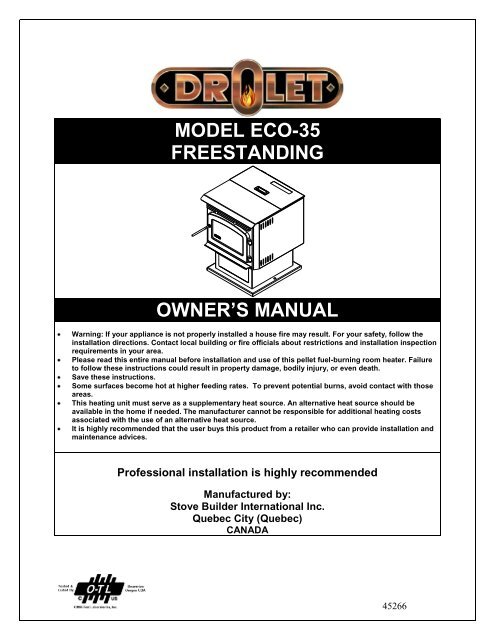
MODEL ECO-35FREESTANDINGOWNER’S MANUALWarning: If your appliance is not properly installed a house fire may result. For your safety, follow <strong>the</strong>installation directions. Contact local building or fire officials about restrictions and installation inspectionrequirements in your area.Please read this entire manual before installation and use of this pellet fuel-burning room heater. Failureto follow <strong>the</strong>se instructions could result in property damage, bodily injury, or even death.Save <strong>the</strong>se instructions.Some surfaces become hot at higher feeding rates. To prevent potential burns, avoid contact with thoseareas.This heating unit must serve as a supplementary heat source. An alternative heat source should beavailable in <strong>the</strong> home if needed. The manufacturer cannot be responsible for additional heating costsassociated with <strong>the</strong> use of an alternative heat source.It is highly recommended that <strong>the</strong> user buys this product from a retailer who can provide installation andmaintenance advices.Professional installation is highly recommendedManufactured by:Stove Builder International Inc.Quebec City (Quebec)CANADA45266
INTRODUCTIONThank you for purchasing <strong>the</strong> ECO-35 pellet stove. You are now prepared to burn wood in <strong>the</strong> mostefficient, convenient way possible. To achieve <strong>the</strong> safest, most efficient and most enjoyableperformance from your stove, you must do three things: 1) Install it properly; 2) Operate it correctly;and 3) Maintain it regularly. The purpose of this manual is to help you do all three.PLEASE read this entire manual before installation and use of this pellet fuel-burning roomheater. Failure to follow <strong>the</strong>se instructions could result in property damage, bodily injury oreven death.Keep this manual handy for future reference.Your ECO-35 has been independently tested to ASTM E1509-04 Standard Specification for roomheaters, pellet fuel burning type 1, UL 2482-1998 and ULC-S627-00 Standard for Solid Fuel RoomHeaters, Oregon Administrative Rules for Mobile Homes (814-23-900 through 814-23-909) andInstallation as a Stove Heater. This pellet stove, when installed, must be electrically grounded inaccordance with local codes, or in <strong>the</strong> absence of local codes, with <strong>the</strong> National Electrical Code,ANSI/NFPA 70 and CSA-C22.1.This appliance is designed specifically for use only with pelletized wood. It is designed for residentialinstallation according to current national and local building codes as a freestanding room heater. It isalso approved as a mobile home heater which is designed for connection to an outside combustion airsource.The stove will not operate using natural draft or without a power source for <strong>the</strong> blower systems andfuel feed system and must not be burned with any type of coal.This stove is designed to provide <strong>the</strong> optimum proportions of fuel and air to <strong>the</strong> fire in order to burnfree of smoke and soot. Any blockage of <strong>the</strong> air supply to or from <strong>the</strong> stove will seriously degrade itsperformance and will be evidenced by a smoking exhaust and a sooting window. For best operation,<strong>the</strong> ash content of <strong>the</strong> pellet fuel should be less than 1% and <strong>the</strong> calorific value approximately 8,200BTU/LB. Avoid high ash content fuels because this will rapidly fill up <strong>the</strong> burn pot and eventually cutoff <strong>the</strong> combustion air supply.Commercial and industrial installations of <strong>the</strong> ECO-35 should not be used since operational control isoften not well managed in <strong>the</strong>se settingsREGISTER YOU WARRANTY ONLINETo receive full warranty coverage, you will need to show evidenceof <strong>the</strong> date you purchased your unit. Keep your sales invoice.We also recommend that you register your warranty online atwww.drolet.caRegistering your warranty online will help us track rapidly <strong>the</strong>information we need on your unit.2
SAFETY PRECAUTIONSDo not operate your stove if yousmell smoke coming from it. Turn it off,monitor it, and call your dealer. Do not unplugit.Never use gasoline, gasoline-typelantern fuel, kerosene, charcoal lighter fluid, orsimilar liquids to start or “freshen up” a fire inthis stove. Keep all such liquids well away from<strong>the</strong> stove while in use.Never block free airflow through <strong>the</strong>open vents of <strong>the</strong> stove.Keep foreign objects out of <strong>the</strong> hopper.Do not throw this manual away. Thismanual has important operating and maintenanceinstructions that you will need at a later time.Always follow <strong>the</strong> instructions in this manual.Do not place clothing or o<strong>the</strong>rflammable items on or near <strong>the</strong> stove.Never try to repair or replace anypart of <strong>the</strong> stove unless instructions are givenin this manual. All o<strong>the</strong>r work should be doneby a trained technician.The stove will not operate during apower outage. If an outage does occur, check<strong>the</strong> stove for smoke spillage and open awindow if any smoke spills into <strong>the</strong> room.Disconnect <strong>the</strong> power cord beforeperforming any maintenance or repairs on <strong>the</strong>stove.NOTE: Turning <strong>the</strong> stove “off” does notdisconnect all power from <strong>the</strong> stove.Do not unplug <strong>the</strong> stove if yoususpect a malfunction. Turn <strong>the</strong> stove off,periodically inspect it, and call your dealer.Contact your local building officials toobtain a permit and information on anyinstallation restrictions or inspectionrequirements in your area. Notify yourinsurance company of this stove as well.This unit must be properly installed toprevent <strong>the</strong> possibility of a house fire. Theinstructions must be strictly adhered to. Do notuse makeshift methods or compromise in <strong>the</strong>installation.Allow <strong>the</strong> stove to cool beforecarrying out any maintenance or cleaning.Ashes must be disposed in a metal containerwith a tight lid and placed on a noncombustible surface well away from <strong>the</strong> homestructure.This stove must be connected to astandard 120 V., 60 Hz grounded electricaloutlet. Do not use an adapter plug or sever <strong>the</strong>grounding plug. Do not route <strong>the</strong> electrical cordunderneath, in front of, or over <strong>the</strong> stove.The exhaust system should bechecked, at a minimum, at least twice a yearfor any build up of soot or creosote.3The viewing door must be closed andlatched during operation.Do not operate <strong>the</strong> stove if <strong>the</strong> flamebecomes dark and sooty or if <strong>the</strong> burnpot overfillswith pellets. Turn <strong>the</strong> stove off, periodicallyinspect it, and call your dealer.Do not touch <strong>the</strong> hot surfaces of <strong>the</strong>heater. Educate all children of <strong>the</strong> danger of ahigh temperature stove. Young children should besupervised when <strong>the</strong>y are in <strong>the</strong> same room as<strong>the</strong> stove.If <strong>the</strong> stove is installed in a room withoutair conditioning, or in an area where directsunlight can shine on <strong>the</strong> unit, it is possible thiscan cause <strong>the</strong> temperature of <strong>the</strong> stove to rise tooperational levels; one of <strong>the</strong> sensors could <strong>the</strong>nmake <strong>the</strong> stove start on its own. It isrecommended that <strong>the</strong> stove be unplugged whennot in use for extended amounts of time (i.e.during <strong>the</strong> summer months).The exhaust system must becompletely airtight and properly installed. All ventconnector joints must be sealed and fastened inaccordance with <strong>the</strong> pellet pipe manufacturer'sinstructions to ensure consistent performance andavoid smoke and ash spillage.Your stove requires periodicmaintenance and cleaning. Failure to maintainyour stove may lead to smoke spillage in yourhome.This stove is designed and approved forpelletized wood fuel only. Any o<strong>the</strong>r type of fuelburned in this heater will void <strong>the</strong> warranty andsafety listing.When installed in a mobile home, <strong>the</strong>stove must be bolted to <strong>the</strong> floor, have outside air,and NOT BE INSTALLED IN A BEDROOM (PerH.U.D. requirements). Check with local buildingofficials.Stove Builder International Inc. grants nowarranty, implied or stated, for <strong>the</strong> installation ormaintenance of your stove, and assumes noresponsibility of any consequential damage(s).
TABLE OF CONTENTSINTRODUCTION ..................................................................................................................................................2SAFETY PRECAUTIONS ....................................................................................................................................3TABLE OF CONTENTS .......................................................................................................................................4STOVE INSTALLATION ....................................................................................................................................6ECO-35 FREESTANDING PELLET STOVE ....................................................................................................6CLEARANCES ...................................................................................................................................................6COMBUSTION AIR SUPPLY ...........................................................................................................................7WHEN OUTSIDE AIR IS NOT USED...............................................................................................................7VENTING ............................................................................................................................................................7FILTERS INSTALLATION AND CLEANING .................................................................................................8EQUIVALENT VENT LENGHT (EVL) ............................................................................................................9INSTALLATION CONFIGURATIONS.............................................................................................................9HORIZONTALLY THROUGH WALL .........................................................................................................9VERTICALLY WITH NEW CHIMNEY SYSTEM .....................................................................................10VERTICALLY INTO EXISTING CHIMNEY SYSTEM ............................................................................10VERTICALLY INTO EXISTING MASONRY FIREPLACE .....................................................................11INSTALLATION THROUGH SIDE OF MASONRY CHIMNEY .............................................................11OPERATION .......................................................................................................................................................12PROPER FUEL ..................................................................................................................................................12PRE-START-UP CHECK .................................................................................................................................12BUILDING A FIRE ...........................................................................................................................................12LIGHTING PROCEDURE ................................................................................................................................12UNIT CONTROLS ............................................................................................................................................13MODE BUTTON ...........................................................................................................................................13FUEL FEED SWITCH ..................................................................................................................................13NOISE REDUCER ........................................................................................................................................13HEAT LEVEL ...............................................................................................................................................13RESET ...........................................................................................................................................................13OPENING DOOR ..............................................................................................................................................13CONVECTION BLOWERS (ROOM AIR FAN) .............................................................................................13COMBEX tm ........................................................................................................................................................14IF THE STOVE RUNS OUT OF PELLETS .....................................................................................................14REFUELING .....................................................................................................................................................14SHUTDOWN PROCEDURE ............................................................................................................................14SAFETY FEATURES .......................................................................................................................................14DAMPER OPERATION ...................................................................................................................................15OPERATING THE STOVE USING A THERMOSTAT .................................................................................16THERMOSTAT INSTALLATION ...................................................................................................................16MODES ..............................................................................................................................................................16OPERATING SAFETY PRECAUTIONS .........................................................................................................18MAINTENANCE .................................................................................................................................................19ASH REMOVAL ...............................................................................................................................................19ASH DISPOSAL ................................................................................................................................................19VACCUM USE ..................................................................................................................................................20CLEANING .......................................................................................................................................................20BLOWERS AND PRESSURE SWITCH PROBE ............................................................................................21CHIMNEY CLEANING ....................................................................................................................................214
RECOMMENDED MAINTENANCE SCHEDULE ........................................................................................22REMOVAL AND REPLACEMENT OF BROKEN DOOR GLASS ...............................................................22TROUBLESHOOTING ......................................................................................................................................23STOVE SHUTS OFF AND SHOWS WARNING CODE “P” .........................................................................23STOVE SHUTS OFF AND DISPLAYS WARNING CODE “E” ....................................................................24STOVE FEEDS PELLETS, BUT WILL NOT IGNITE AND SHOWS WARNING CODE “L” ...................25STOVE FEEDS PELLETS, BUT WILL NOT IGNITE AND SHOWS WARNING CODE “I” .....................25STOVE STOPS FEEDING PELLETS AND SHOWS WARNING CODE “O” .............................................25STOVE STOPS FEEDING PELLETS AND SHOWS WARNING CODE “H” .............................................26STOVE STOPS FEEDING PELLETS AND SHOWS WARNING CODE “d” ..............................................26SMOKE SMELL COMING BACK INTO THE HOME ..................................................................................26AUGER MOTOR STOPS FEEDING PELLETS AND COMES BACK ON ..................................................26GLASS SOOTS UP VERY FAST ....................................................................................................................27FLAME IS LAZY, DARK, AND HAS BLACK TIPS .....................................................................................27AFTER STOVE HAS BEEN ON FOR A WHILE, THE BURNPOT OVERFILLS .......................................27WARNING CODES ..........................................................................................................................................28SMOKE SMELL OR SOOT BUILD-UP ..........................................................................................................28ELECTRICAL DIAGRAM ................................................................................................................................29ELECTRIC SHOCK ..........................................................................................................................................29REPLACEMENT PARTS...................................................................................................................................30APPENDIX A .......................................................................................................................................................31APPENDIX B .......................................................................................................................................................32DROLET LIMITED LIFETIME WARRANTY ..............................................................................................335
SIDE WALLADJACENT WALLSTOVE INSTALLATIONECO-35 FREESTANDING PELLET STOVEWidth: 22 1/4”Height: 28 1/2”Depth: 25 3/16”Weight: 190 lbs.Flue size: 3” or 4”Hopper Capacity: Up to 35 lbs.(This can vary slightly depending on pellet size, length, and diameter)EPA status: exemptBurn rate: 1.3 lbs to 4.1 lbs per hourBTU range: 8,200 to 35000Electrical consumption: 3.5 Amps lighting cycle2.5 Amps. continuous dutyControl board fuses: Main: 7.5A-250V fastblowIgniter: 5A-250V fastblowElectrical requirement: 120VAC 15AApproved installations: mobile home, conventionalPREPARATIONFactory packaging must be removed, and some minor assembly work isrequired prior to installation :BACK WALL3"2" *6"Figure 1Back wall installation*HORIZONTAL INSTALLATIONThe black knobs must be attached to heat exchanger rods;The coil handle must be attached to handle rod;Filters may be inserted between finger guard and convectionblower (see “filters assembly” section).ADJACENT WALL2"3"CLEARANCESThe ECO-35 has been tested and listed for installation in regular andmobile homes.(refer figure 1 & 2)FLOOR PROTECTION: minimum 6” in <strong>the</strong> front and 6” on each side. Thestove must be placed on a continuous (grouted joints) non-combustiblematerial such as ceramic tile, cement board, brick, 3/8” millboard orequivalent, or o<strong>the</strong>r approved or listed material suited for floor protection.NOTE: ceramic tile, or any tile, requires a continuous sheet beneath toprevent <strong>the</strong> possibility of embers falling through to <strong>the</strong> combustible floor ifcracks or separation should occur in <strong>the</strong> finished surface, this wouldinclude floor protection for Built-in raised hearths. Check local codes forapproved alternatives.Clearances are measured from <strong>the</strong> sides, back and face (door opening) orstove body (refer to fig. 3).DO NOT USE MAKESHIFT MATERIALS OR COMPROMISES IN THEINSTALLATION OF THIS UNIT.Figure 2Corner installation3"2"INSTALL VENT WITH CLEARANCES SPECIFIED BY THE VENTMANUFACTURER.6" 6"This heating unit must serve as a supplementary heat source. An alternative heat sourceshould be available in <strong>the</strong> home if needed. The manufacturer cannot be responsible foradditional heating costs associated with <strong>the</strong> use of an alternative heat source.It is highly recommended that <strong>the</strong> user buys this product from a retailer who can provideinstallation and maintenance advices.6"Figure 3Floor protection6
COMBUSTION AIR SUPPLYFor a mobile home installation <strong>the</strong> stove must be connected to an outsidesource of combustion air. A 3” inside diameter metallic pipe, ei<strong>the</strong>r flexibleor rigid, may be attached to <strong>the</strong> inlet at <strong>the</strong> stove’s rear (refer to figures 4, 5& 6). A rodent guard (minimum ¼” wire mesh) must be used at <strong>the</strong>terminus (refer to figure 5). All connections must be secured and airtight byei<strong>the</strong>r using <strong>the</strong> appropriately sized hose clamp and/or UL-181-AP foil tape.AIRINTAKEEXHAUSTFor mobile home installations only: No combustion air supply mayexceed 10 feet.Sources of Outside Combustion AirA hole in <strong>the</strong> wall behind <strong>the</strong> stove.(Figure 5)A hole in floor near stove rear terminating only in a ventilatedcrawl space.(Figure 6)WHEN OUTSIDE AIR IS NOT USEDIf outside air is not used, it is important that combustion air be easilyavailable to <strong>the</strong> air inlet. A closable outside air register can be used intightly insulated homes.VENTINGThe ECO-35 is certified for use with a vent certified to UL-103 or ULCS629M and a chimney type vent certified to UL-641 or ULC-S-609-M89and ULC/ORD C441-M90, with 3” or 4” inner diameter. In Canada, werecommend that you use a listed pellet vent that meets <strong>the</strong> ULC S-609-M89and ULC/ORD C441-M90 Standards. For <strong>the</strong> United States, werecommend that you use a listed pellet vent that meets <strong>the</strong> UL-641, 7 <strong>the</strong>dition Standard. This unit can be vented in an existing chimney with <strong>the</strong>addition of a liner if <strong>the</strong> chimney is more than 4” in diameter. Class “A”chimney is not required. Refer to <strong>the</strong> instructions provided by <strong>the</strong> vent orchimney manufacturer, especially when passing through a wall, ceiling orroof.Your venting system should have at least one foot of vertical rise foreach foot of horizontal run. The total vertical rise should never beless than 3 feet (see Appendix A).This is a pressurized exhaust system. All vent connector joints must besealed and fastened in accordance with <strong>the</strong> pellet pipe manufacturer'sinstructions to ensure consistent performance and avoid smoke and ashspillage.DO NOT CONNECT THIS UNIT TO A CHIMNEY FLUE SERVINGANOTHER APPLIANCE.Figure 4Rear viewTRIMCOLLARFigure 5Fresh air supplyRODENTGUARDDO NOT INSTALL A FLUE DAMPER IN THE EXHAUST VENTINGSYSTEM OF THIS UNIT.INSTALL VENT AT CLEARANCES SPECIFIED BY THE VENTMANUFACTURER.WARNING: DO NOT INSTALL IN SLEEPING ROOMCAUTION: THE STRUCTURAL INTEGRITY OF THE MANUFACTUREDHOME FLOOR, WALL, AND CEILING/ROOF MUST BE MAINTAINEDVENTILATEDCRAWL SPACEFigure 6Ventilated crawl space7
FILTERS INSTALLATION AND CLEANINGThe two filters for your convection blowers are supplied with <strong>the</strong> owner’s manual. Although <strong>the</strong> filters are not mandatory, <strong>the</strong>y are useful to prevent dustfrom being dispersed into <strong>the</strong> room where <strong>the</strong> stove is located. If you install <strong>the</strong> filters, please make sure that <strong>the</strong>y are cleaned on a regular basis as perour recommended maintenance schedule. This is particularly critical if you have animals in your house, such as a dog or a cat. Filters that are notcleaned can clog up and cause your stove to overheat. You may also damage or burn <strong>the</strong> convection blowers. In order to install <strong>the</strong> filters, simply insert<strong>the</strong>m in <strong>the</strong> slot just above <strong>the</strong> blower’s finger guard. To clean <strong>the</strong> filters, use a vacuum or remove <strong>the</strong> filters and rinse <strong>the</strong>m with hot water.8
EQUIVALENT VENT LENGHT (EVL)The longer <strong>the</strong> run of pipe in your installation, <strong>the</strong> greater <strong>the</strong> restriction in<strong>the</strong> system. Therefore, larger diameter pipe should be used.Use 4” pipe if you have more than 15 feet of Equivalent Vent Length(EVL).90 DEGREE ELBOWHorizontal runs shall not exceed 10 feet of EVL.To calculate EVL, use <strong>the</strong> following conversions table:Qty Type of pipe EVL equivalent(ft)1 90° elbow or “T” 51 45° elbow 3FOLLOW CHIMNEY ORVENT MANUFACTURER'SINSTRUCTIONSWALLTHIMBLE45 DEGREE ELBOWTERMINATIONCOLLARWALLSTRAPCLEAN OUTTEE1 ft Horizontal pipe run 11 ft Vertical pipe run 0.5NOTE: At altitudes above 3,000 feet, we suggest <strong>the</strong> use of 4” diametervent at an EVL of 7 feet or more.Here is an example on how to calculate <strong>the</strong> EVL of your installation. (SeeFigure 8)(3 x 4’ of vertical length = 12’ x 0.5 = 6 EVL) + (1 x elbow or "T" = 5 EVL) +(2 x 1’ of horizontal length = 2 EVL)Figure 7Venting through wallVERTICAL ROOF VENTVERTICAL LENGTH 4' EVL = 4 X 0.5' = 2'Total EVL = (6 + 5 +2) = 13. So 3” diameter vent is acceptable.Note: Do not count <strong>the</strong> outside termination (goose neck) in <strong>the</strong> EVLcalculation.INSTALLATION CONFIGURATIONSA- HORIZONTALLY THROUGH WALL(refer to Figure 7 & 8, or 10)NOTE: Follow Vent chimney manufacturer’s instructions.1. Position stove, adhering to clearances shown in Figures 1 & 2.FOLLOW CHIMNEY ORVENT MANUFACTURER'SINSTRUCTIONSWALLTHIMBLEVERTICAL LENGTH 4' EVL = 4 X 0.5' = 2'WALLSTRAPVERTICAL LENGTH4' EVL = 4 X 0.5' = 2'CLEAN OUTTEE90° ELBOW "T" LEE = 5'2. Locate position of hole in wall; directly behind stove exhaust vent(refer to figure 4).3. Always maintain 3” clearance from combustible materials.4. Install Vent wall thimble per Vent manufacturer’s instructions.1' HORIZONTAL RUN EVL = 1'1' HORIZONTAL RUN EVL = 1'Figure 8Venting trough wall5. Attach enough piping to penetrate and extend at least 6 inchesbeyond <strong>the</strong> exterior wall. There should always be at least one foot ofvertical rise for each foot of horizontal run (see Appendix A). At least3 feet of vertical rise are needed in all cases. A longer vertical rise willfavour a better exhaust.6. To reduce <strong>the</strong> risk of smoke spillage, never terminate with a horizontalrun. If your system terminates with a horizontal run, add at least 3 feetof vertical rise (see Appendix A).7. Attach cap and seal outside wall thimbles with non-hardeningwaterproof mastic.Locate terminations: a) not less than 3 feet above any forced air inletlocated within 10 feet; b) not less than 4 feet below or horizontally from,or one foot above, any door, window or gravity air inlet into any building;c) not less than two feet from an adjacent building and not less than 7 feetabove grade when located adjacent to a public walkway. Mobile homeinstallations must use a spark arrester. O<strong>the</strong>r restrictions may apply, suchas <strong>the</strong> need to maintain a minimum distance to a gas meter. US andCanadian Standards may vary. Consult <strong>the</strong> vent manufacturer’sinstructions.Termination should not be located so that hot exhaust gases can ignitetrees, shrubs, or grasses or be a hazard to children. Exhaust gases canreach temperatures of 500ºF and cause serious burns if touched.9
B - VERTICALLY WITH NEW CHIMNEY SYSTEM(Refer to Figure 9 – Venting through roof)NOTE: Follow Vent chimney manufacturer’s instructions.OPTION: To achieve a centered vertical installation, a 45º elbow and aclean-out tee can be used to offset <strong>the</strong> pipe from <strong>the</strong> exhaust outlet to <strong>the</strong>rear center of <strong>the</strong> stove.OPTION: Install Vent elbow in place of clean-out tee. Locate stove. Dropplumb bob to center of tee outlet, mark point on ceiling. Install ceilingsupport and Vent pipe per Vent manufacturer’s instructions.1. Always maintain 3” clearance from combustible materials. Whenpassing through additional floors or ceilings, always install firestopspacer.2. After lining up for hole in roof, cut ei<strong>the</strong>r a round or square hole in roof,always 3” larger all <strong>the</strong> way around pipe. Install upper edge and sidesof flashing under roofing materials, nail to <strong>the</strong> roof along upper edge.Do not nail lower edge. Seal nail heads with flexible waterproofsealant.3. Apply flexible, waterproof sealant where <strong>the</strong> storm collar meets <strong>the</strong>vent. Slide storm collar down until it sits on <strong>the</strong> flashing. Seal andinstall cap. Mobile home installations must use a spark arrester.C - VERTICALLY INTO EXISTING CHIMNEY SYSTEMAs an alternative, 3” or 4” Vent can be run inside existing chimney totermination(Figure 11). This is <strong>the</strong> preferred method.Follow guidelines for equivalent vent length.Figure 9Venting through roofFOLLOW CHIMNEY ORVENT MANUFACTURER'SINSTRUCTIONSWALLTHIMBLEFOR BASEMENT INSTALLATIONA 4" PIPE IS RECOMMANDEDWALLSTRAPCLEAN OUTTEEFigure 10Basement installationCLEAN OUTTEEFigure 11Venting through existing chimney10
VERTICALLY INTO EXISTING MASONRY FIREPLACENOTE: Follow Vent chimney manufacturer’s instructions.1. Have <strong>the</strong> masonry chimney inspected by a qualified chimney sweepor installer to determine its structural condition.2. You will need a pipe length equal to <strong>the</strong> chimney height from <strong>the</strong>hearth plus 18 inches.3. Install a blanking plate and <strong>the</strong> chimney pipe, and if used <strong>the</strong> outsideair pipe, as shown in Figure 12.4. Attach <strong>the</strong> DuraVent adapter, a section of pipe and clean out tee,making sure <strong>the</strong> clean out tee is centered in <strong>the</strong> chimney flue area.Use RTV, metallic tape, and a minimum of three self-taping screws atall joint connections to ensure a tight seal.5. Position <strong>the</strong> stove, adhering to <strong>the</strong> clearances in Figures 1 & 2.6. Measure and build chimney top plate. Cut out holes for chimney pipe,and if used <strong>the</strong> outside air pipe. Install and seal with non-hardeningmastic to prevent water leakage. Install vent cap.FOLLOW CHIMNEY ORVENT MANUFACTURER'SINSTRUCTIONS3"VERTICAL ROOF VENT18"TOP PLATEBLANKING PLATEOPTIONALOUTSIDE AIRCLEAN OUTTEEINSTALLATION THROUGH SIDE OF MASONRY CHIMNEYNOTE: Follow Vent chimney manufacturer’s instructions.1. Position <strong>the</strong> stove, adhering to <strong>the</strong> clearances in Figures 1 & 2. Mark<strong>the</strong> center of <strong>the</strong> hole where <strong>the</strong> pipe is to pierce <strong>the</strong> masonrychimney.2. It will be necessary to break out <strong>the</strong> masonry around <strong>the</strong> location of<strong>the</strong> pipe center mark. Use a 4-inch diameter hole for 3-inch pipe and5-inch diameter hole for 4-inch pipe.3. Measure and build chimney top plate. Cut out holes for chimney pipe,and if used <strong>the</strong> outside air pipe.FOLLOW CHIMNEY ORVENT MANUFACTURER'SINSTRUCTIONSFigure 12Venting through masonrychimney3"OPTIONALOUTSIDE AIRVERTICAL ROOF VENT18"TOP PLATE4. Install <strong>the</strong> tee on <strong>the</strong> bottom of <strong>the</strong> vertical pipe system and lower itdown <strong>the</strong> chimney until <strong>the</strong> center branch of <strong>the</strong> tee is level with <strong>the</strong>center of <strong>the</strong> hole in <strong>the</strong> masonry, as shown in Figure 13.5. Install and seal <strong>the</strong> top plate from step 3 with non-hardening mastic.Slip <strong>the</strong> storm collar over <strong>the</strong> pipe, and while holding <strong>the</strong> pipe at <strong>the</strong>proper elevation, affix <strong>the</strong> collar with a minimum of three ¼” stainlesssteel sheet metal screws. Seal all joints and seams around <strong>the</strong> collar.WALLTHIMBLE6. Connect <strong>the</strong> horizontal pipe by pushing it through <strong>the</strong> hole in <strong>the</strong>masonry and lining it up with <strong>the</strong> branch in <strong>the</strong> tee. Push <strong>the</strong> pipe into<strong>the</strong> tee while twisting it to lock it into <strong>the</strong> tee.7. If desired, once <strong>the</strong> horizontal pipe is in place, <strong>the</strong> space between <strong>the</strong>pipe and masonry may be filled with high-temperature grout.CLEAN OUTTEEInstall <strong>the</strong> trim collar. An adjustable pipe length and adapter may beneeded to finish <strong>the</strong> connection to <strong>the</strong> stove.Figure 13Venting through side ofmasonry chimney11
UNIT CONTROLSThe blowers and automatic fuel supply are controlled from <strong>the</strong> panel on <strong>the</strong> ECO-35. The control panel functions are as follows:Note:1- To display <strong>the</strong> available functions, just touch <strong>the</strong> control board at any place2- Select <strong>the</strong> desired function*The display will turn itself off after 2 minutes.MODE BUTTONWhen <strong>the</strong> on-off button is pressed, <strong>the</strong> stove will automatically ignite. The heat level must be selected manually to adjust <strong>the</strong> stove’s heat output to<strong>the</strong> desired level. If <strong>the</strong> <strong>the</strong>rmostat mode is selected, <strong>the</strong> stove will automatically modulate between <strong>the</strong> lowest heat level and <strong>the</strong> heat levelselected to keep <strong>the</strong> room temperature at <strong>the</strong> <strong>the</strong>rmostat’s setting. If <strong>the</strong> set room temperature is achieved while <strong>the</strong> stove has been running at <strong>the</strong>lowest heat level for more than 45 minutes, <strong>the</strong> unit will automatically shut off and will start ano<strong>the</strong>r ignition cycle only when <strong>the</strong> <strong>the</strong>rmostat calls forheat again(stove have to cool down completely prier to ignite). No fire starter is necessary to ignite <strong>the</strong> unit. The auger will feed fuel for 4 minutesand <strong>the</strong> electronic igniters will stay on for 10 minutes. If <strong>the</strong> unit doesn’t ignite within 15 minutes, <strong>the</strong> stove will wait for 5 minutes and will start asecond ignition cycle. If ignition fails a second time, a warning messagewill appear on control panel.The Heat Level may be selected during <strong>the</strong> ignition cycle and can be modified in heating mode. However, <strong>the</strong> unit will only feed fuel at <strong>the</strong> desiredheat level setting when <strong>the</strong> heat sensor located into <strong>the</strong> stove will receive a signal indicating that <strong>the</strong> unit has been fully ignited. This may takeanywhere between 10 and 15 minutes.FUEL FEED SWITCHBy activating this function, <strong>the</strong> stove start to feed for 1 minute and <strong>the</strong> display start to blink. You can stop <strong>the</strong> distribution by touching <strong>the</strong> sign asecond time or by starting <strong>the</strong> stove.CAUTION: THIS FUNCTION CAN ONLY BE OPERATED WHEN THE STOVE IS IN “OFF” POSITION. THE FUEL FEED SWITCH IS USED TOPRIME THE AUGER WHEN THE AUGER IS EMPTY.NOISE REDUCERThe convection blowers speed varies directly with <strong>the</strong> fuel feed rate. A dimmed display indicates that <strong>the</strong> blowers are in low noise mode.When <strong>the</strong> “NOISE REDUCER” button is pushed, <strong>the</strong> convection blowers will switch to <strong>the</strong>ir lowest speed. The convection blowers will remain at<strong>the</strong>ir lowest speed unless <strong>the</strong> stove reaches a certain temperature. If this occurs, <strong>the</strong> convection blowers will go back to <strong>the</strong>ir highest setting to cooldown <strong>the</strong> stove. The low noise button will have to be pressed again for <strong>the</strong> convection blowers to go back to <strong>the</strong>ir lowest speed. Please note that<strong>the</strong> difference in noise level may not be noticeable on units manufactured after 2006. Those units already use two ultra-quiet tubeaxial convectionblowers that produce a very low noise even at full speed.HEAT LEVELBy pressing <strong>the</strong> gradient, you can set <strong>the</strong> pellet feed rate and hence <strong>the</strong> heat output of your stove. The levels of heat output will change and eachgradient will indicate <strong>the</strong> level from 1 to 6.RESETThe reset button has to be used to clear any warning on <strong>the</strong> control and restart your stove. This button is only available when you get a warningcode on <strong>the</strong> display.OPENING DOORThe door should be open only for maintenance purposes.CONVECTION BLOWERS (ROOM AIR FAN)Upon starting your stove, <strong>the</strong> convection blowers will not come on until <strong>the</strong> stove’s heat exchanger warms up. This usually takes about 10 to 15 minutesfrom start-up. Speed will vary with <strong>the</strong> selected feed rate, except if <strong>the</strong> noise reducer mode has been activated.13
COMBEX tmYour stove uses a unique patented technology called COMBEX. As opposed to most o<strong>the</strong>r pellet stoves, which use only anexhaust blower, your ECO-35 uses a motor on which are mounted two housings with impeller blades. One housing serves forcombustion, and <strong>the</strong> o<strong>the</strong>r for exhaust. This is why we refer to <strong>the</strong> combustion/exhaust blower throughout this manual. TheCOMBEX system balances combustion air and uptake to provide clean, worry-free combustion which is less dependent on <strong>the</strong>leak-tightness of <strong>the</strong> device and <strong>the</strong> quality of <strong>the</strong> combustible.IF THE STOVE RUNS OUT OF PELLETSThe fire goes out and <strong>the</strong> auger motor and blowers will run until <strong>the</strong> stove cools down. This will take a few minutes.After <strong>the</strong> stove’s components stop running, a warning message will appear .To restart, press , refill <strong>the</strong> hopper , and press until pellets begin to fall into <strong>the</strong> burn pot. Press to start <strong>the</strong> unit.DAMPER CONTROLThe damper control on <strong>the</strong> stove’s in <strong>the</strong> right hand side panel. This control is necessary due to <strong>the</strong> varied burn characteristics of individual installationsand different pellet brands. It allows you to improve <strong>the</strong> efficiency of your stove. Providing correct combustion air will reduce <strong>the</strong> frequency of cleaningyour glass door and prevent <strong>the</strong> rapid build-up of creosote inside your stove and chimney.You should adjust <strong>the</strong> damper based on <strong>the</strong> fire’s appearance. A low, reddish, dirty fire can be improved by increasing <strong>the</strong> air supply using <strong>the</strong> dampercontrol. A “blow torch” fire can be improved by reducing <strong>the</strong> air supply Figure 14.Through trial and error, you will find <strong>the</strong> best setting. Consult your dealer if you need help.REFUELINGWe recommend that you not let <strong>the</strong> hopper drop below 1/4 full. If <strong>the</strong> reload lid stays for open more than 3 minutes, a warningwill appear. Torestart, press button, and <strong>the</strong>n press .KEEP HOPPER LID CLOSED AT ALL TIMES EXCEPT WHEN REFILLING. THE HOPPER MAY BE FILLED WHILE THE STOVE IS OPERATING.DO NOT OVERFILL HOPPER. DO NOT TOUCH THE UNIT WITH THE PELLET BAG. HOT SURFACE MAY MELT THE BAG.SHUTDOWN PROCEDURETurning your stove off is a matter of pressing on <strong>the</strong> control panel. The blowers will continue to operate until internal firebox temperatures havefallen to a preset level. The stove cannot restart until it has shut down completely.SAFETY FEATURESa. Your stove is equipped with a re-settable high temperature switch (also called heat sensor or heat switch). The switch has a reset button on itsbackside. Like a circuit breaker, once tripped, <strong>the</strong> reset button will have to be pushed before you can restart <strong>the</strong> stove. The high temperatureswitch is <strong>the</strong>re to protect <strong>the</strong> stove from overheating in case of an evacuation problem, a control board problem, a blower problem, or any o<strong>the</strong>rproblem causing <strong>the</strong> unit to overheat. The manufacturer recommends that you call your dealer if this occurs as it may indicate a more seriousproblem. A service call may be required.NOTE: If an overheating situation occurs, <strong>the</strong> high temperature switch (called <strong>the</strong> L-250 manual reset) will automatically shut down <strong>the</strong> auger(fuel feed system) and a warning codewill appear.b. If <strong>the</strong> combustion blower fails, an air pressure switch will automatically shut down <strong>the</strong> auger and a warning message will appear. Thissafety feature is to prevent <strong>the</strong> unit from burning fuel when <strong>the</strong> combustion/exhaust blower has failed, <strong>the</strong>refore preventing combustion fumesfrom spilling into <strong>the</strong> room.14
c. If <strong>the</strong> temperature in <strong>the</strong> auger rises beyond a certain acceptable level, two high temperature switches located under and above auger housingwill stop <strong>the</strong> fuel feed system and a warningwill appear.CODE BEFORE RESETING TO RESETH1, H2, H3 Heat exchanger and/or exhaust systemOR H4 is/are clogged. Refer to <strong>the</strong> owner’s manualfor maintenance procedures.Press simultaneously for 2 secondsand.*** After 3 attempts, reset is no longer possible, call SBI technical support.DAMPER OPERATIONPOÊLE / STOVEFERMÉ / CLOSE OUVERT / OPENFigure 14Damper operation15
OPERATING THE STOVE USING A THERMOSTATA <strong>the</strong>rmostat may help you maintain a constant house temperatureautomatically. A low voltage <strong>the</strong>rmostat or 24 Volt <strong>the</strong>rmostat is required. Afixed wall mount or hand held model can be used. The control panel can beset up two ways to operate your stove in <strong>the</strong>rmostatic mode.THERMOSTAT INSTALLATIONUnplug <strong>the</strong> stove from <strong>the</strong> power outlet.Connect two <strong>the</strong>rmostat wires to <strong>the</strong> terminal block located on <strong>the</strong>lower right side of <strong>the</strong> back of <strong>the</strong> stove. To do so, loosen <strong>the</strong> twoscrews and insert <strong>the</strong> wires in <strong>the</strong> terminals. Tighten <strong>the</strong> two screws.(See Figure 15)If you are using a wireless wall <strong>the</strong>rmostat or a hand held <strong>the</strong>rmostaticremote control, you can locate <strong>the</strong> receiver behind <strong>the</strong> stove’s backpanel, on <strong>the</strong> right end side, just below <strong>the</strong> terminal block. Mostreceivers are already equipped with quick-connect terminals. Simplyunplug <strong>the</strong> PC board wires connected to <strong>the</strong> back of <strong>the</strong> terminal blockand connect <strong>the</strong>m directly with <strong>the</strong> receiver’s terminals. Location of<strong>the</strong> <strong>the</strong>rmostat is very important to obtain <strong>the</strong> best comfort andefficiency from you ECO-35. The <strong>the</strong>rmostat should be mounted 50inch from <strong>the</strong> floor on a wall located 15 to 20 feet from <strong>the</strong> stove. Youshould avoid an installation directly in front of <strong>the</strong> stove to avoidcycling.(See Figure 16)MODESTHERMOSTATWIRE TERMINALFigure 15Thermostat terminalTHERMOSTATIC MODETo use this mode, <strong>the</strong> <strong>the</strong>rmostat button must be pushedupon starting <strong>the</strong> stove. The heat setting is <strong>the</strong>n selected using <strong>the</strong>“Heat Level” selector. When set in <strong>the</strong>rmostatic mode, <strong>the</strong> stove willautomatically run at <strong>the</strong> heat level selected until <strong>the</strong> set roomtemperature is reached. When that occurs, <strong>the</strong> stove will switch toheat setting #1 (lowest) until <strong>the</strong> <strong>the</strong>rmostat calls for heat again. Theconvection blowers will also slow to its lowest speed. When <strong>the</strong><strong>the</strong>rmostat calls for heat again, <strong>the</strong> stove will increase its feed rate tomatch <strong>the</strong> heat setting selected.N.B.: If <strong>the</strong> room temperature remains stable and <strong>the</strong> <strong>the</strong>rmostatdoes not call for heat during at least 45 minutes, <strong>the</strong> stove will shutdown. When <strong>the</strong> <strong>the</strong>rmostat calls for heat again, <strong>the</strong> stove will start anignition cycle. Once <strong>the</strong> ignition cycle is completed, <strong>the</strong> stove willincrease its feed rate to match <strong>the</strong> heat setting selected.16
N.B.: It is possible to change <strong>the</strong> setting of your unit such that if <strong>the</strong><strong>the</strong>rmostat does not call for heat after 45 minutes, <strong>the</strong> unit will remainat <strong>the</strong> lowest heat setting (#1) but will not shut down (this is <strong>the</strong> PILOTON mode). The stove will remain at <strong>the</strong> lowest heat level until <strong>the</strong><strong>the</strong>rmostat calls for heat again. If you prefer that your unit runsfollowing that logic, you need to change <strong>the</strong> setting to PILOT ON by<strong>the</strong> pressing <strong>the</strong> following two buttons on <strong>the</strong> PC Board:First press , hold it, and <strong>the</strong>n press . Hold <strong>the</strong> twobuttons for a couple of seconds.Once you do that, <strong>the</strong> letters P, I, L, O, T, O, N will appear on <strong>the</strong> PCBoard to let you know that you are in <strong>the</strong> “PILOT ON” mode. If youwish to go back to <strong>the</strong> default <strong>the</strong>rmostatic mode (i.e. <strong>the</strong> unit shutsdown after 45 minutes if <strong>the</strong> <strong>the</strong>rmostat does not call for heat), simplypress <strong>the</strong> same two buttons again for a couple of seconds. Theletters P, I, L, O, T, A, U, T, O will appear on <strong>the</strong> PC Board to let youknow that you are in <strong>the</strong> “PILOT AUTO” mode.SHOULD BE AVOIDEDNOTE: When in <strong>the</strong>rmostatic mode:You should not operate <strong>the</strong> manual control or play with <strong>the</strong>temperature setting.YOUR THERMOSTAT SHOULD BE INSTALLED BY ANAUTHORIZED DEALER OR SERVICE PERSON.D = MINIMUM DISTANCE 15 FEETFigure 16Thermostat location17
OPERATING SAFETY PRECAUTIONSPLEASE READ THIS!a. If you notice a smoldering fire (burnpot full but no visible flame) AND a heavy smoke buildup in firebox,immediately TURN OFF <strong>the</strong> stove, but DO NOT unplug it. Do not open <strong>the</strong> door, change <strong>the</strong> damper setting ortamper with any controls on <strong>the</strong> stove. Wait until smoke inside <strong>the</strong> firebox clears and blowers shut down. Do asinstructed in “PRE-START-UP CHECK” and “LIGHTHING PROCEDURE“, <strong>the</strong>n attempt to restart <strong>the</strong> fire. If <strong>the</strong>problem persists, contact your dealer. Please note that smoke build-up during ignition may occur. Smoke canaccumulate in <strong>the</strong> firebox for a few seconds just before <strong>the</strong> igniter is hot enough to fire-up <strong>the</strong> pellets in <strong>the</strong> burn pot.This is normal. As soon <strong>the</strong>re is fire in <strong>the</strong> burn pot, smoke will disappear.b. DO NOT STORE OR USE FLAMMABLE LIQUIDS, ESPECIALLY GASOLINE, IN THE VICINITY OF YOURDROLET STOVE. NEVER USE A GAS OR PROPANE TORCH, GASOLINE, GASOLINE-TYPE LANTERN FUEL,KEROSENE, CHARCOAL LIGHTER FLUID OR SIMILAR FLUIDS TO START OR “FRESHEN UP” A FIRE INTHIS HEATER.c. WARNING: DO NOT OVERFIRE THIS STOVE. This may cause serious damage to your stove and void yourwarranty. It also may create a fire hazard in your home. IF ANY EXTERNAL PART OF THE UNIT BEGINS TOGLOW, YOU ARE OVERFIRING. Immediately press <strong>the</strong> switch on <strong>the</strong> control panel. DO NOT UNPLUGYOUR STOVE. If you leave your house and your stove is not connected to a <strong>the</strong>rmostat or a fresh air supply, do notleave it at <strong>the</strong> maximum setting. If <strong>the</strong> ambient air in a confined room becomes to hot, <strong>the</strong> stove may overheatand <strong>the</strong> <strong>the</strong>rmal protection on <strong>the</strong> combustion/exhaust motor may be activated, causing <strong>the</strong> motor to stop.d. KEEP ALL HOUSEHOLD COMBUSTIBLES, SUCH AS FURNITURE, DRAPES, TOYS, ETC. AT LEAST THREEFEET FROM THE STOVE.e. Maintain proper ventilation. It is important that adequate oxygen be supplied to <strong>the</strong> fire for <strong>the</strong> combustion process.Modern houses are often so well insulated that it may become necessary to open a window slightly or install anoutside air vent to provide sufficient combustion air.f. Since heating with solid fuel is potentially hazardous, even with a well made and thoroughly tested stove, it would bewise to install strategically placed smoke detectors and have a fire extinguisher in a convenient location, near an exit.g. Do not open <strong>the</strong> stove door when operating unless necessary. This will create a dirty, inefficient burn and could allowsmoke spillage or sparks to escape.h. Stove must not be operated by young children or someone unfamiliar with stove’s operation.i. Do not service or clean this appliance without disconnecting <strong>the</strong> power cord.j. Do not abuse <strong>the</strong> door glass by striking, slamming or similar trauma. Do not operate <strong>the</strong> stove with <strong>the</strong> glass removed,cracked or broken.k. High ambient temperature in summer time may cause <strong>the</strong> heat sensors on <strong>the</strong> stove to activate <strong>the</strong> blowers,disconnect <strong>the</strong> stove when not used for extended periods.18
MAINTENANCEFAILURE TO CLEAN AND MAINTAIN THIS UNIT AS INDICATED CANRESULT IN POOR PERFORMANCE AND SAFETY HAZARDS. NEVERCLEAN WHEN HOT.NOTE: Inspect burn pot periodically to see that holes have not becomeplugged. If so, clean thoroughly.BAFFLEASH REMOVALThe ECO-35 has an ash bin located below <strong>the</strong> firebox To remove ashes:a. Make sure fire is out and <strong>the</strong> firebox is cool.b. Open <strong>the</strong> door and remove <strong>the</strong> baffle from <strong>the</strong> firebox. Slide each sideof <strong>the</strong> baffle toward <strong>the</strong> center to remove(Figure 20). Close <strong>the</strong> door.MAINWALLc. With <strong>the</strong> door closed, clean heat exchanger tubes by activating <strong>the</strong>cleaning rod back and forth.(Figure 18)d. Open <strong>the</strong> door and remove <strong>the</strong> burn pot by grasping it and pullingstraight out. Scrape <strong>the</strong> burn pot with a scraper if necessary. Make surethat <strong>the</strong> burn pot holes are not plugged. Empty ashes from <strong>the</strong> burn potinto <strong>the</strong> ash drawer through <strong>the</strong> opening at <strong>the</strong> bottom of <strong>the</strong> firebox.Put <strong>the</strong> burn pot back in place. Make sure it is level and pushed all <strong>the</strong>way in. Make sure <strong>the</strong> burn pot gasket is in place before putting<strong>the</strong> burn pot back. Absence of this can cause ignition problem.Figure 17Baffle & exhaust access panele. Sweep <strong>the</strong> ashes in <strong>the</strong> firebox into <strong>the</strong> ash drawer through <strong>the</strong> openingat <strong>the</strong> bottom of <strong>the</strong> firebox or vacuum to remove ashes.WARNING: Make sure ashes are cool to <strong>the</strong> touchbefore using a vacuum. See “VACUUM USE”.f. Periodically remove and empty <strong>the</strong> ash drawer (see Figure 19)in <strong>the</strong>pedestal below <strong>the</strong> ash lip. Dispose of ashes properly.CLEANINGRODg. Put <strong>the</strong> ash drawer back into place, making sure <strong>the</strong> ash plug is intoplace and maintain a good seal. A air leak will affect <strong>the</strong> combustion.ASH DISPOSALAshes should be placed in a metal container with a tight-fitting lid. Theclosed container or ashes should be placed on a non-combustible surface oron <strong>the</strong> ground, well away from all combustible materials pending finaldisposal. If ashes are disposed of by soil burial or o<strong>the</strong>rwise locallydispersed, <strong>the</strong>y should be retained in <strong>the</strong> closed container until all cindershave thoroughly cooled.Figure 18Cleaning rodFigure 19Ash drawer19
VACCUM USEIf a vacuum is used to clean your stove, we suggest using a vacuum designed forashes.Some regular vacuums and shop vacs leak ash into <strong>the</strong> room. Your vacuum or shopvac may have a special filter or bag available to eliminate this leakage.CLEANINGa. Heat Exchange Tubes – Your ECO-35 stove is designed with a built-inheat exchanger tube cleaner. This should be used weekly to removeaccumulated ash on <strong>the</strong> tubes. Slide <strong>the</strong> cleaning rod back and forth twoor three times from front to back (refer to figure 18). When finished, push<strong>the</strong> cleaning rod back in.b. Baffle: Remove <strong>the</strong> baffle and scrape off ashes. Slide both sides toward<strong>the</strong> center to remove <strong>the</strong> baffle(Figure 20) Use a vacuum is necessary. Insome cases, you will need to remove creosote on <strong>the</strong> baffle, which canaccumulate rapidly under certain conditions. A small wire brush can beused. It is important to remove this creosote because it is highlycombustible and could cause premature corrosion.*When replacing <strong>the</strong> baffle, make sure that <strong>the</strong> open side of <strong>the</strong> baffleis located on <strong>the</strong> left.c. Chamber walls: Periodically, you must vacuum <strong>the</strong> ashes that may haveaccumulated on <strong>the</strong> main walls of <strong>the</strong> combustion chamber. START BYREMOVING THE DECORATIVE MASONRY-LIKE PANELS, WHICH ARESIMPLY HELD BY CLIPS. The use of a vacuum is necessary. There isalso a cleaning outlet located behind <strong>the</strong> left side panel of <strong>the</strong> combustionchamber. Remove this panel using a screw driver. Loosen <strong>the</strong> adjustmentscrews <strong>the</strong>n remove <strong>the</strong> securing screws(Figure 21). Slide <strong>the</strong> wall towardright(Figure 22), tilt it (Figure 23) <strong>the</strong>n remove it from <strong>the</strong> combustionchamber. Scrape off ashes. You will notice a small rectangular cleaningoutlet. Inspect behind this outlet (see Figure 24) Insert <strong>the</strong> vacuum tipthrough <strong>the</strong> cleaning outlet and clean thoroughly. REPEAT THISOPERATION AT LEAST ONCE PER TON OF PELLETS BURNED UNTILYOU ARE FAMILIAR WITH HOW ASHES ACCUMULATE WITH YOUROPERATING PRACTICES.d. Convection blowers - Clean <strong>the</strong> blower’s protective wire mesh regularlyas dust and hair build-ups on <strong>the</strong> mesh will reduce <strong>the</strong> efficiency of <strong>the</strong>blowers and may cause <strong>the</strong> stove to overheat.Figure 20Baffle removalSECURINGSCREWSADJUTMENTSCREWSFigure 21Figure 22Figure 23Figure 2420
BLOWERS AND PRESSURE SWITCH PROBEDANGER: RISK OF ELECTRIC SHOCK.SERVICING UNIT.DISCONNECT POWER BEFOREBlower Cleaning – Over a period of time, ashes or dust may collect on <strong>the</strong>blades of both <strong>the</strong> combustion/exhaust blower and convection blower.Periodically, <strong>the</strong> blowers should be cleaned as <strong>the</strong> ash and dust canimpede performance. The combustion/exhaust blower can be accessed byopening <strong>the</strong> left, right, and back panels.(Figure 25) To clean <strong>the</strong> blades in<strong>the</strong> combustion housing, insert <strong>the</strong> vacuum tip through <strong>the</strong> air inlet damperopening located on <strong>the</strong> side of <strong>the</strong> combustion housing. Clean thoroughly.To clean <strong>the</strong> blades in <strong>the</strong> exhaust housing, use a screw driver to remove<strong>the</strong> cleaning access panel located on <strong>the</strong> side of <strong>the</strong> metal box covering <strong>the</strong>housing. Insert <strong>the</strong> vacuum tip through <strong>the</strong> cleaning outlet and clean <strong>the</strong>blades thoroughly.Pressure switch probe cleaning - Ashes may accumulate on inside tip of<strong>the</strong> pressure switch probe connector. Use a mesh pad or wire brush toclean <strong>the</strong> connector and blow inside <strong>the</strong> tube to make sure it’s free ofobstruction.NOTE: When cleaning, be careful not to bend fan blades. Some stove owners lightly spray ananti-creosote chemical on <strong>the</strong> fire to help reduce creosote formation within <strong>the</strong> stove.PROBE CONNECTORFigure 25Exhaust blower cleaningCHIMNEY CLEANINGa. Creosote Formation – When any wood is burned slowly, it produces tar and o<strong>the</strong>r organic vapours, which combine with expelled moisture to formcreosote. The creosote vapours condense in <strong>the</strong> relatively cool chimney flue or a newly started fire or from a slow-burning fire. As a result, creosoteresidue accumulates on <strong>the</strong> flue lining. When ignited, this creosote makes an extremely hot fire, which may damage <strong>the</strong> chimney or even destroy<strong>the</strong> house. Despite <strong>the</strong>ir high efficiency, pellet stoves can accumulate creosote under certain conditions.b. Fly Ash – This accumulates in <strong>the</strong> horizontal portion of an exhaust run. Though non-combustible, it may impede <strong>the</strong> normal exhaust flow. It should<strong>the</strong>refore be periodically removed.c. Inspection and Removal – The chimney connector and chimney should be inspected annually or per ton to determine if a creosote or fly ash builduphas occurred. If creosote has accumulated, it should be removed to reduce <strong>the</strong> risk of a chimney fire. Inspect <strong>the</strong> system at <strong>the</strong> stove connectionand at <strong>the</strong> chimney top. Cooler surfaces tend to build creosote deposits quicker, so it is important to check <strong>the</strong> chimney from <strong>the</strong> top as well as from<strong>the</strong> bottom.The creosote should be removed with a brush specifically designed for <strong>the</strong> type of chimney in use. A qualified chimney sweep can perform this service. Itis also recommended that before each heating season <strong>the</strong> entire system be professionally inspected, cleaned and, if necessary, repaired.To clean <strong>the</strong> chimney, disconnect <strong>the</strong> vent from <strong>the</strong> stove.21
RECOMMENDED MAINTENANCE SCHEDULEUse this as a guide under average-use conditions.ComponentsDailyWeeklyor after+/- 10 bagsBurn Pot Empty Empty / BrushGlass Wipe CleanHeat Exchanger TubesActivate cleaning rodevery time you load<strong>the</strong> stoveActivate cleaningrod and vacuumTwice a yearor after+/- 25 bagsAnnuallyorper ton of pelletsBaffleEmpty and brushConvection BlowerFiltersVacuumAshe DrawerEmptyCombustion Chamber Vacuum Vacuum / BrushLeft-hand ChannelVacuumExhaust BlowerVacuumPressure Switch TapBrushVenting System Inspect SweepGasketsInspectHopperEmpty / VacuumGasket around door and door glass should be inspected and repaired or replaced when necessary (see“REPLACEMENT PARTS”).REMOVAL AND REPLACEMENT OF BROKEN DOOR GLASSWhile wearing lea<strong>the</strong>r gloves (or any o<strong>the</strong>r gloves suitable for handling broken glass), carefully remove any loose pieces of glass from <strong>the</strong> door frame.Dispose of all broken glass properly. Return <strong>the</strong> damaged glass to your DROLET Dealer for replacement. It is critical that you replace <strong>the</strong> glass with agenuine one supplied by your dealer.22
TROUBLESHOOTINGWhen your stove acts up, your first reaction may be to call for help. This guide may save you time and money by enabling you to resolve simpleproblems yourself. Problems can be caused by: 1) poor fuel; 2) poor operation or maintenance; 3) poor installation; 4) component failure; 5) factorydefect. You can usually solve problems related to 1 and 2. Your dealer can solve problems related to 3, 4 and 5. Refer to ELECTRICAL DIAGRAM andREPLACEMENT PARTS section to help identify and locate stove parts.Should you need to contact your dealer or <strong>the</strong> manufacturer, please photocopy and fill out <strong>the</strong> form in AppendixB. Try to answer as many questions as you can. Have it handy when you call. This will help you obtain a muchfaster service.STOVE SHUTS OFF AND SHOWS WARNING CODE“P”Possible Causes:Possible Remedies: (Unplug stove first when possible)1. Airflow pressure switch hose or hose connector tip are blocked. Pull out air hose from <strong>the</strong> airflow switch and blow through it. If air flowsfreely, <strong>the</strong> hose and tube are fine. If air will not flow throw <strong>the</strong> hose, use athin wire to clear <strong>the</strong> blockage. If <strong>the</strong> problem occurs again shortly after ,you may have to remove accumulation on <strong>the</strong> pressure switch probelocated inside of exhaust blower housing(refer to maintenance section)2. The air inlet, burn pot, interior combustion air chambers, combustionblower, or exhaust pipe are blocked with ash or foreign material.Follow all cleaning procedures in <strong>the</strong> maintenance section of <strong>the</strong> owner’smanual.3. Vent pipe is incorrectly installed. Check to make sure vent pipe installation meets <strong>the</strong> criteria in <strong>the</strong> owner’s manualas well as <strong>the</strong> pipe manufacturer’s recommendations.4. The pressure switch connections are faulty. Check <strong>the</strong> connectors attached to <strong>the</strong> pressure switch.5. The pressure switch wires are pulled loose from <strong>the</strong> connectors on<strong>the</strong> wiring harness.Check to see whe<strong>the</strong>r <strong>the</strong> wires are loose at <strong>the</strong> connectors.6. Combustion/exhaust blower failure. This blower must turn on when you start <strong>the</strong> unit. If it does not, make sure <strong>the</strong>re ispower on <strong>the</strong> connections. If <strong>the</strong> power is connected, <strong>the</strong> motor is probablydefective; if <strong>the</strong>re is no power, see #7.7. Control board is not sending power to <strong>the</strong> combustion/exhaust blower. If <strong>the</strong>re is no power going to <strong>the</strong> combustion blower, check all connections. If allwires are properly connected, you have a defective control board.8. Control board not sending power to pressure switch. There should be 120-volt going through <strong>the</strong> pressure switch when <strong>the</strong>stove is on. You will need a technician to perform this test.9. Airflow pressure switch has failed (very rare). To test <strong>the</strong> airflow pressure switch, you need to disconnect <strong>the</strong> air hose from <strong>the</strong>blower casing. With <strong>the</strong> o<strong>the</strong>r end still attached to <strong>the</strong> switch, very gently suck on<strong>the</strong> loose end of <strong>the</strong> hose (you may want to completely disconnect <strong>the</strong> hose from<strong>the</strong> stove and <strong>the</strong> switch first and make sure it is clear). If you hear a click, <strong>the</strong>switch is working. BE CAREFUL: TOO MUCH SUCTION CAN DAMAGETHE SWITCH.23
STOVE SHUTS OFF AND DISPLAYS WARNING CODE “E”Possible Causes:Possible Remedies: (Unplug stove first when possible)1. The hopper is empty. Refill <strong>the</strong> hopper.2. The burn pot holes are blocked. Remove <strong>the</strong> burn pot and clean it thoroughly.3. The air damper is open too much for <strong>the</strong> low feed setting. If <strong>the</strong> stove is on <strong>the</strong> low setting, you may need to close <strong>the</strong> damper all <strong>the</strong> way.Slide <strong>the</strong> air supply control toward <strong>the</strong> minimum setting.4. The air inlet, interior chambers, or exhaust system is partly blocked. Follow all cleaning procedures in <strong>the</strong> maintenance section of <strong>the</strong> owner’smanual.5. The auger motor has failed. Remove <strong>the</strong> auger motor from <strong>the</strong> auger shaft and try to run <strong>the</strong> motor separately bypressing <strong>the</strong> fuel feed button on <strong>the</strong> control board. If <strong>the</strong> motor turns, <strong>the</strong> shaft isjammed on something. If <strong>the</strong> motor does not turn, <strong>the</strong> motor is defective or <strong>the</strong>re is afaulty connection with <strong>the</strong> control board. To remove <strong>the</strong> auger motor, take <strong>the</strong> rearpanel off <strong>the</strong> stove body. Loosen <strong>the</strong> two screws holding <strong>the</strong> motor to <strong>the</strong> augershaft.6. The auger shaft is jammed. Remove <strong>the</strong> auger shaft from <strong>the</strong> auger housing. Start by emptying <strong>the</strong> hopper. Take<strong>the</strong> rear panel off <strong>the</strong> stove body. Then take <strong>the</strong> auger motor off by removing <strong>the</strong>screws that hold <strong>the</strong> motor to <strong>the</strong> auger shaft. Once <strong>the</strong> motor is out, remove <strong>the</strong> fourscrews on <strong>the</strong> steel plate that holds <strong>the</strong> auger shaft to <strong>the</strong> auger housing. Then rotate<strong>the</strong> bottom end of <strong>the</strong> auger shaft down towards you until you can pull <strong>the</strong> shaftdown out of <strong>the</strong> stove. After you have removed <strong>the</strong> shaft, inspect it for bent flights,burrs, or broken welds. Remove any foreign material that may have caused <strong>the</strong> jam.Also, check <strong>the</strong> auger housing for signs of damage such as burrs, rough spots, orgrooves cut into <strong>the</strong> metal that could have caused a jam. Clean <strong>the</strong> auger housingthoroughly to remove all pellet dust.7. The <strong>the</strong>rmistor heat sensor has malfunctioned. The <strong>the</strong>rmistor is a heat sensor located on <strong>the</strong> exhaust housing. Its functionis to tell <strong>the</strong> control board that <strong>the</strong> unit has ignited properly by measuring <strong>the</strong>heat in <strong>the</strong> exhaust. The pellet stove will not start feeding pellets at <strong>the</strong>desired heat setting until it has received a signal from <strong>the</strong> <strong>the</strong>rmistor heatsensor. If <strong>the</strong> <strong>the</strong>rmistor heat sensor is bad, <strong>the</strong> unit will stop after <strong>the</strong>ignition cycle. If this situation occurs, call your dealer or technician.24
STOVE FEEDS PELLETS, BUT WILL NOT IGNITE ANDSHOWS WARNING CODE “L”Possible Causes:Possible Remedies:1. Air damper open too far for ignition. Adjust <strong>the</strong> air supply to <strong>the</strong> minimum setting for startup. In some situations, it maybe necessary to have <strong>the</strong> damper completely closed for ignition to take place. Once<strong>the</strong>re is a flame, <strong>the</strong> damper can be adjusted to <strong>the</strong> desired feed setting.2. Blockage in igniter tube or inlet for igniter tube. Remove <strong>the</strong> burn pot and clean it thoroughly. Make sure that all openings are clear.Find <strong>the</strong> place where <strong>the</strong> igniter tube comes out of <strong>the</strong> burn pot housing. It is a smalltube located on <strong>the</strong> back of <strong>the</strong> burn pot housing. Make sure it is clear. Make sure<strong>the</strong>re is no debris around <strong>the</strong> igniter element or inside <strong>the</strong> igniter tube.3. Defective igniter element. Supply power directly to <strong>the</strong> igniter element. Watch <strong>the</strong> tip of <strong>the</strong> igniter from <strong>the</strong>front of <strong>the</strong> stove. After about 2 minutes, <strong>the</strong> tip should glow. If it does not, <strong>the</strong>element is defective and must be replaced. You may need a technician to performthis test.4. The <strong>the</strong>rmistor heat sensor has malfunctioned. The <strong>the</strong>rmistor is a heat sensor attached to <strong>the</strong> exhaust housing. Its function is totell <strong>the</strong> control board that <strong>the</strong> unit has ignited properly by measuring <strong>the</strong> temperaturein <strong>the</strong> exhaust. The stove will not feed pellets at <strong>the</strong> desired heat setting until ithas received a signal from <strong>the</strong> <strong>the</strong>rmistor heat sensor. If <strong>the</strong> <strong>the</strong>rmistor heat sensoris bad, <strong>the</strong> unit will go out and stop after <strong>the</strong> ignition cycle. If this situation occurs,call your dealer or technician.5. The control board is not sending power to <strong>the</strong> igniter. Check <strong>the</strong> voltage going to <strong>the</strong> igniter during ignition. It should be a full current. If<strong>the</strong> voltage is lower than full current, check <strong>the</strong> wiring. If <strong>the</strong> wiring is functional andproperly connected, <strong>the</strong> board is defective. You will need a technician to performthis test.6. The burn pot gaskets are missing or have to be replaced Burn pot gaskets are located in <strong>the</strong> metal ring at <strong>the</strong> bottom of <strong>the</strong> burn pot. Thesegaskets prevent heat lost from <strong>the</strong> igniters to get a fastest ignition.STOVE FEEDS PELLETS, BUT WILL NOT IGNITEAND SHOWS WARNING CODE “I”Possible Causes:Possible Remedies:1. The igniter fuse on <strong>the</strong> control board has blown. Remove <strong>the</strong> control board and check at <strong>the</strong> back to see if <strong>the</strong> F3 fuse is good,; ifnot replace it with a 5 Amp 250V fuse. Plug <strong>the</strong> stove back and try to run <strong>the</strong>unit.STOVE STOPS FEEDING PELLETS AND SHOWSWARNING CODE “O”Possible Causes:Possible Remedies:1. The L-250 manual reset high temperature switch has tripped. Using <strong>the</strong> owner’s manual, locate <strong>the</strong> L-250 high temperature switch.There is a red button on it. Press <strong>the</strong> red button. If you hear a click, <strong>the</strong>high limit had tripped. Reset <strong>the</strong> stove. The stove should now functionnormally. YOU NEED TO INSPECT YOUR UNIT AT THIS POINT. The F-250 high temperature switch will trip if <strong>the</strong> unit overheats. There might bea problem with ano<strong>the</strong>r component or <strong>the</strong> installation, causing <strong>the</strong> stove tooverheat. Make sure that <strong>the</strong> convection blowers work. If one of <strong>the</strong>convection blowers has failed, this can cause <strong>the</strong> unit to overheat. Cleanany dust off of <strong>the</strong> windings and blades of <strong>the</strong> convection blower. Callyour dealer or a technician if you get this code again.25
STOVE STOPS FEEDING PELLETS AND SHOWSWARNING CODE “H”Possible Causes:1. One of <strong>the</strong> two L-250 automatic high temperature switch hastripped.Possible Remedies:The L-250 automatic high temperature switches are located on<strong>the</strong> top and bottom of <strong>the</strong> auger housing They send a signal to <strong>the</strong>control board if <strong>the</strong> auger housing overheats. Wait until <strong>the</strong>stove cools down AND THEN INSPECT YOUR UNIT.Improper installation, poor maintenance, or a defective ormissing component may be causing <strong>the</strong> stove to overheat. Reset<strong>the</strong> stove and restart it. Call a technician if you get this codeagain.*See procedure below to restart <strong>the</strong> stove.CODE BEFORE RESETING TO RESETH1, H2, H3OR H4Heat exchanger and/or exhaust systemis/are clogged. Refer to <strong>the</strong> owner’s manualfor maintenance procedures.Press simultaneously for 2 seconds <strong>the</strong> reseticons .*** After 3 attempts, reset is no longer possible. Call SBI technical support.andSTOVE STOPS FEEDING PELLETS AND SHOWSWARNING CODE “d”Possible Causes:Possible Remedies:1. The hopper lid has stayed open for more than 3 minutes As a security measure, <strong>the</strong> auger will stop turning and feeding pellets assoon as <strong>the</strong> hopper lid opens. It will resume normal operation as soon as<strong>the</strong> hopper lid is closed. However, if <strong>the</strong> hopper lid stays open for morethan 3 minutes, <strong>the</strong> unit will stop and a code “d” will appear on <strong>the</strong> controlboard. Close <strong>the</strong> hopper lid. Reset <strong>the</strong> unit and start it again.SMOKE SMELL COMING BACK INTO THE HOMEPossible Causes:Possible Remedies:1. There is a leak in <strong>the</strong> vent pipe system. Inspect all vent pipe connections. All vent connector joints must besealed and fastened in accordance with <strong>the</strong> pellet pipe manufacturer'sinstructions to ensure consistent performance and avoid smoke and ashspillage.2. The gasket on <strong>the</strong> combustion/exhaust blower housing hasgone bad.Inspect <strong>the</strong> gasket on <strong>the</strong> combustion/exhaust blower housing to makesure it is in good shape and replace if necessary.AUGER MOTOR STOPS FEEDING PELLETS AND COMES BACK ONPossible Causes:Possible Remedies:1. The auger motor is overheatingand tripping <strong>the</strong> internaltemperature shutoff (<strong>the</strong>rmalprotector).Start by emptying <strong>the</strong> hopper. Follow procedure described in warning code “E” section #6.26
THE STOVE IS RUNNING BUT DISPLAYS WARNING CODEPossibles Causes:Warning generated by a power failure while <strong>the</strong> stove was running.Possibles Remedies:The stove will restart on <strong>the</strong> initial setting once it cools off.Note: For a short power failure (less than 5 seconds), <strong>the</strong> stove will continue to function at<strong>the</strong> selected speed.The control board does not display any information.Possible Causes: Possible Remedies :1. A fuse on <strong>the</strong> control board has blown. Remove <strong>the</strong> control board. Check if <strong>the</strong> F2 fuse on <strong>the</strong> back of it appearsto be bad. Replace it with a 7.5 Amp 250 Volt fuse. Plug <strong>the</strong> stove back inand try to run <strong>the</strong> unit.GLASS SOOTS UP VERY FASTFLAME IS LAZY, DARK, AND HAS BLACK TIPSAFTER STOVE HAS BEEN ON FOR A WHILE, THE BURNPOT OVERFILLSPossible Causes:Possible Remedies:1. Stove or vent pipe is clogged, which restricts airflow through <strong>the</strong> burn pot. Follow all cleaning procedure in <strong>the</strong> maintenance section of <strong>the</strong> owner’smanual.2. Vent pipe installed improperly. Check to make sure <strong>the</strong> vent pipe has been installed according to <strong>the</strong>instructions in <strong>the</strong> owner’s manual.3. The air damper is too far closed for a higher setting. Slide <strong>the</strong> air supply to a higher setting and try to burn <strong>the</strong> unit again.4. Burn pot holes are blocked. Remove <strong>the</strong> burn pot and clean it thoroughly.5. Blockage in air intake pipe. Visually inspect <strong>the</strong> air intake pipe that leads into <strong>the</strong> burn pot for foreignmaterial.6. Combustion/exhaust blower is not spinning fast enough. Test <strong>the</strong> RPM on <strong>the</strong> blower (separately – bypassing <strong>the</strong> control board) after <strong>the</strong>blades have been cleaned. The RPM should be approximately 3000 RPM. Youwill need a technician to perform this test.7. Bad pellets(Applies to “GLASS SOOTS UP AT A VERY FAST RATE” Only)The brand or <strong>the</strong> batch of pellets used may be of poor quality. If possible, try adifferent brand of pellets. You might also want to try a brand that is made froma different type of wood (softwood vs. hardwood). Different woods havedifferent characteristics that affect <strong>the</strong> combustion. Your pellets may also be toohumid. Make sure you store your fuel properly, in a dry ventilated area.27
MESSAGEWARNING CODESCORRESPONDING WARNINGPressure switch error.L-250 automatic high temperature switches, located under and above <strong>the</strong> auger.L-250 manual reset high temperature switch, located beside convection blower.Hopper is emptyLighting error.Hopper lid stayed open more than 3 minutes.Inverted polarity in power outlet.(Will not keep <strong>the</strong> stove from operating)Power outageIgniter fuse is burnt outSMOKE SMELL OR SOOT BUILD-UPBecause it is a wood-burning device, your ECO-35 may emit a faint wood-burning odor. If this increases beyond normal, or if you notice an unusual sootbuild-up on walls or furniture, check your exhaust system carefully for leaks. All joints should be properly sealed. Also clean your stove, followinginstructions in “MAINTENANCE”. If problem persists, contact your dealer.28
ELECTRICAL DIAGRAMTHERMOSTATTERMINALSN.O.HOPPER LIDSWITCHN.O.CONTROLBOARDDISPLAY BOARDTHERMISTORL2(LINE COMMON)L1(LINE HOT)L1(LINE NO CONNECTED)FRAME GROUNDL-250RESETN.C.AIR FLOWPRESSURESWITCHN.O.COMBUSTION/EXHAUSTBLOWERAUGERMOTORIGNITERL-250N.C.F-160N.O.CONVECTIONBLOWERFigure 26Electrical diagramCONVECTIONBLOWERAUGERMOTORHIGH TEMPERATURESWITCH L-250AUTOMATICPRESSURESWITCHCONVECTIONBLOWERFRESH AIRINTAKECONVECTIONBLOWEREXHAUSTHIGH TEMPERATURESWITCH F-160THERMISTORFigure 27Components left sideCLEANINGACCESSPANELPOWERCORDTHERMOSTATTERMINALFigure 28Components rearEXHAUST/COMBUSTIONBLOWERHIGH TEMPERATURESWITCH L-250MANUAL RESETIGNITERFigure 29Components right sideAIR SUPPLYCONTROLELECTRIC SHOCKIn order to verify <strong>the</strong> grounding and polarity of <strong>the</strong> power outlet, <strong>the</strong> control board sends a low voltage impulse to <strong>the</strong> stove’s frame.If <strong>the</strong> polarity is wrong or if <strong>the</strong> outlet is not properly grounded, you may feel an electric shock when you touch <strong>the</strong> stove; this low voltage impulse isharmless and connecting your stove to a grounded outlet with <strong>the</strong> right polarity will keep this from happening and protect your electronics againstdamages from power surge.29
REPLACEMENT PARTSContact an Authorized DROLET Dealer to obtain any of <strong>the</strong>se parts. Never use substitute materials.Use of non-approved parts can result in poor performance and safety hazards.ITEM PART #Airflow Pressure Switch 44029Air Switch Hose 49004Auger Motor 44038Burn PotSE49045Burn pot gasket(2 requires) 21045Control Board(Touch screen) 44022PC Board 44102Combustion/Exhaust Blower Assembly SE44101Convection Blower 44100Door GasketAC06100Hot Rod Igniter 44030Thermistor 44095F-160 Convection blower heat sensor 44058L-250 Automatic High Temp. Switch 44059L-250 Manual Reset High Temp. Switch 44041Window Gasket (7’)AC06400Convection blower gasket 21177Combustion/Exhaust blower gasket 21109Auger 24017Loading lid switch 44098Loading lid handle 30527Baffle30
APPENDIX AHORIZONTAL AND VERTICAL VENT CHARTPossible Verticalvent length (feet)If you plot your ventingsystem configuration onthis chart, your wall orroof termination should bewithin <strong>the</strong> grid.Possible Horizontalvent length (feet)Let’s imagine an installation consisting of a horizontal vent coming out at <strong>the</strong> back of <strong>the</strong> stove on a total distance of 8 feet.This horizontal run is followed by a Tee and a 6-foot vertical rise. This type installation is not acceptable. As you can see,<strong>the</strong> vent termination is clearly outside <strong>the</strong> allowed configuration zone on <strong>the</strong> chart. The venting system does not have atleast one foot of vertical rise for each foot of horizontal run.Instead, if <strong>the</strong> installation consisted of a horizontal vent coming out at <strong>the</strong> back of <strong>the</strong> stove on a total distance of 4 feet,followed by a Tee and a 6-foot vertical rise, it would be acceptable. The installation would end be within <strong>the</strong> allowableconfiguration zone on <strong>the</strong> chart since it would have at least one foot of vertical rise for each foot of horizontal run.Fur<strong>the</strong>rmore, <strong>the</strong> total vertical rise would be at least 3-foot high.WARNING: To reduce <strong>the</strong> risk of smoke spillage, never terminate with a horizontal run. If your system terminateswith a horizontal run, add at least 3 feet of vertical rise.31
INSPECTION AND REPAIR FORMAPPENDIX BE xchangerB affleLeft interior channelHopperEvacuation blowerCLEANINGPART DAILY +/- 10 bag s +/- 25 bag sYES NOYES NOYES NOYES NOYES NO+/- 50 bag sQty111 feet1 feetType of pipeT or 90°45° elbowHoriz. LenghtVert. LenghtEVL5 feet3 feet1 feet0.5 feetUse 4” pipe if you have more than 15feet of Equivalent Vent Length (EVL).Blower bladesPressure systemBurn potConvection blower filterEvacuation systemGasketsYESNOYESNOYES NOYES NOYES NO YES NOYES NOThe longer <strong>the</strong> run of pipe inyour installation,<strong>the</strong> more restriction <strong>the</strong>re is in<strong>the</strong> system.Therefore, larger diameter pipeshould be used.INDICATE APPLIANCE CODEDESCRIPTION OF THE PROBLEM32
DROLET LIMITED LIFETIME WARRANTYThe warranty of <strong>the</strong> manufacturer extends only to <strong>the</strong> original consumer purchaser and is not transferable. This warranty covers brandnew products only, which have not been altered, modified nor repaired since shipment from factory. Proof of purchase (dated bill ofsale), model name and serial number must be supplied when making any warranty claim to your DROLET dealer.This warranty applies to normal residential use only. Damages caused by misuse, abuse, improper installation, lack ofmaintenance, over firing, negligence, accident during transportation, power failures, downdrafts, or venting problems are notcovered by this warranty.This warranty does not cover any scratch, corrosion, warping, or discoloration caused by over firing, abrasives or chemical cleaners. Anydefect or damage caused by <strong>the</strong> use of unauthorized parts or o<strong>the</strong>rs than original parts void this warranty. An authorized qualifiedtechnician must perform <strong>the</strong> installation in accordance with <strong>the</strong> instructions supplied with this product and all local and national buildingcodes. Any service call related to an improper installation is not covered by this warranty.The manufacturer may require that defective products be returned or that digital pictures be provided to support <strong>the</strong> claim. Returnedproducts are to be shipped prepaid to <strong>the</strong> manufacturer for investigation. If a product is found to be defective, <strong>the</strong> manufacturer willrepair or replace such defect. Transportation fees to ship <strong>the</strong> product back to <strong>the</strong> purchaser will be paid by <strong>the</strong> manufacturer. Repair workcovered by <strong>the</strong> warranty, executed at <strong>the</strong> purchaser’s domicile by an authorized qualified technician requires <strong>the</strong> prior approval of <strong>the</strong>manufacturer. Labour cost and repair work to <strong>the</strong> account of <strong>the</strong> manufacturer are based on predetermined rate schedule and must notexceed <strong>the</strong> wholesale price of <strong>the</strong> replacement part. All parts and labour costs covered by this warranty are limited according to <strong>the</strong> tablebelow.The manufacturer at its discretion may decide to repair or replace any part or unit after inspection and investigation of <strong>the</strong> defect. Themanufacturer may, at its discretion, fully discharge all obligations with respect to this warranty by refunding <strong>the</strong> wholesale price of anywarranted but defective parts. The manufacturer shall in no event be responsible for any special, indirect, consequential damages of anynature, which are in excess of <strong>the</strong> original purchase price of <strong>the</strong> product. A one-time replacement limit applies to all parts benefitingfrom a lifetime coverage. This warranty applies to products purchased after March 1 st , 2009.DESCRIPTIONCombustion chamber (welds only), heat exchanger (welds only), auger, andcastings.Stainless steel firebox components, surrounds and heat shields, ash drawer,pedestal, trims (aluminum extrusions), and plating* (defective manufacture).Carbon steel firebox components, burn pot, glass retainers, and handleassembly.Blowers, auger motor, PC board, igniter, heat sensors, switches, wiring,rheostat, and o<strong>the</strong>r controls.Ceramic glass (<strong>the</strong>rmal breakage only*), paint (peeling), gaskets, insulation,ceramic logs, masonry-like panels, and ceramic fibre blankets.*Pictures requiredWARRANTY APPLICATIONPARTS LABOURLifetime3 years5 years 3 years3 years 1 year2 years 1 year1 year n/aShall your unit or a components be defective, contact immediately your DROLET dealer. Prior to your call make sure you have <strong>the</strong>following information necessary to your warranty claim treatment:Your name, address and telephone number;Bill of sale and dealer’s name;Serial number and model name as indicated on <strong>the</strong>nameplate fixed to <strong>the</strong> back of your unit;Nature of <strong>the</strong> defect and any relevant information.Before shipping your unit or defective component to our plant, you must obtain from your DROLET dealer anAuthorization Number. Any merchandise shipped to our plant without authorization will be refused automatically andreturned to sender.33