
Create successful ePaper yourself
Turn your PDF publications into a flip-book with our unique Google optimized e-Paper software.
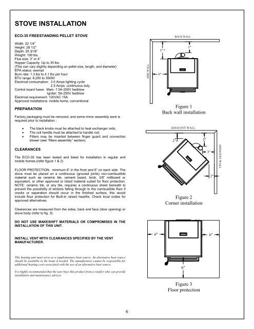
SIDE WALLADJACENT WALLSTOVE INSTALLATIONECO-35 FREESTANDING PELLET STOVEWidth: 22 1/4”Height: 28 1/2”Depth: 25 3/16”Weight: 190 lbs.Flue size: 3” or 4”Hopper Capacity: Up to 35 lbs.(This can vary slightly depending on pellet size, length, and diameter)EPA status: exemptBurn rate: 1.3 lbs to 4.1 lbs per hourBTU range: 8,200 to 35000Electrical consumption: 3.5 Amps lighting cycle2.5 Amps. continuous dutyControl board fuses: Main: 7.5A-250V fastblowIgniter: 5A-250V fastblowElectrical requirement: 120VAC 15AApproved installations: mobile home, conventionalPREPARATIONFactory packaging must be removed, and some minor assembly work isrequired prior to installation :BACK WALL3"2" *6"Figure 1Back wall installation*HORIZONTAL INSTALLATIONThe black knobs must be attached to heat exchanger rods;The coil handle must be attached to handle rod;Filters may be inserted between finger guard and convectionblower (see “filters assembly” section).ADJACENT WALL2"3"CLEARANCESThe ECO-35 has been tested and listed for installation in regular andmobile homes.(refer figure 1 & 2)FLOOR PROTECTION: minimum 6” in <strong>the</strong> front and 6” on each side. Thestove must be placed on a continuous (grouted joints) non-combustiblematerial such as ceramic tile, cement board, brick, 3/8” millboard orequivalent, or o<strong>the</strong>r approved or listed material suited for floor protection.NOTE: ceramic tile, or any tile, requires a continuous sheet beneath toprevent <strong>the</strong> possibility of embers falling through to <strong>the</strong> combustible floor ifcracks or separation should occur in <strong>the</strong> finished surface, this wouldinclude floor protection for Built-in raised hearths. Check local codes forapproved alternatives.Clearances are measured from <strong>the</strong> sides, back and face (door opening) orstove body (refer to fig. 3).DO NOT USE MAKESHIFT MATERIALS OR COMPROMISES IN THEINSTALLATION OF THIS UNIT.Figure 2Corner installation3"2"INSTALL VENT WITH CLEARANCES SPECIFIED BY THE VENTMANUFACTURER.6" 6"This heating unit must serve as a supplementary heat source. An alternative heat sourceshould be available in <strong>the</strong> home if needed. The manufacturer cannot be responsible foradditional heating costs associated with <strong>the</strong> use of an alternative heat source.It is highly recommended that <strong>the</strong> user buys this product from a retailer who can provideinstallation and maintenance advices.6"Figure 3Floor protection6