PORT WORKS DESIGN MANUAL PART 3 Guide To - The University ...
PORT WORKS DESIGN MANUAL PART 3 Guide To - The University ...
PORT WORKS DESIGN MANUAL PART 3 Guide To - The University ...

Create successful ePaper yourself
Turn your PDF publications into a flip-book with our unique Google optimized e-Paper software.
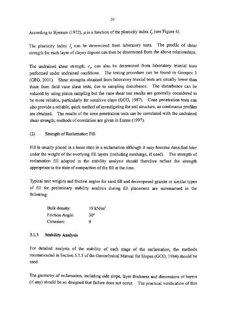
30According to Bjerrum (1972), //is a function of the plasticity index I p (see Figure 4).<strong>The</strong> plasticity index I p can be determined from laboratory tests.<strong>The</strong> profile of shearstrength for each layer of clayey deposit can then be determined from the above relationships.<strong>The</strong> undrained shear strength, c u9 can also be determined from laboratory triaxial testsperformed under undrained conditions. <strong>The</strong> testing procedure can be found in Geospec 3(GEO, 2001). Shear strengths obtained from laboratory triaxial tests are usually lower thanthose from field vane shear tests, due to sampling disturbance. <strong>The</strong> disturbance can bereduced by using piston sampling but the vane shear test results are generally considered tobe more reliable, particularly for sensitive clays (GCO, 1987). Cone penetration tests canalso provide a reliable, quick method of investigating the soil structure, as continuous profilesare obtained. <strong>The</strong> results of the cone penetration tests can be correlated with the undrainedshear strength; methods of correlation are given in Lunne (1997).(2) Strength of Reclamation FillFill is usually placed in a loose state in a reclamation although it may become densified laterunder the weight of the overlying fill layers (including surcharge, if used). <strong>The</strong> strength ofreclamation fill adopted in the stability analysis should therefore reflect the strengthappropriate to the state of compaction of the fill at the time.Typical unit weights and friction angles for sand fill and decomposed granite or similar typesof fill for preliminary stability analysis during fill placement are summarised in thefollowing:Bulk density: 19 kN/m 3Friction Angle: 30°Cohesion: 03.1.3 Stability AnalysisFor detailed analysis of the stability of each stage of the reclamation, the methodsrecommended in Section 5.3.5 of the Geotechnical Manual for Slopes (GCO, 1984) should beused.<strong>The</strong> geometry of reclamation, including side slope, layer thickness and dimensions of berms(if any) should be so designed that failure does not occur. <strong>The</strong> practical verification of this