Autodesk Inventor 2010 What's New - Autodesk Inventor Wizard
Autodesk Inventor 2010 What's New - Autodesk Inventor Wizard
Autodesk Inventor 2010 What's New - Autodesk Inventor Wizard
- No tags were found...

You also want an ePaper? Increase the reach of your titles
YUMPU automatically turns print PDFs into web optimized ePapers that Google loves.
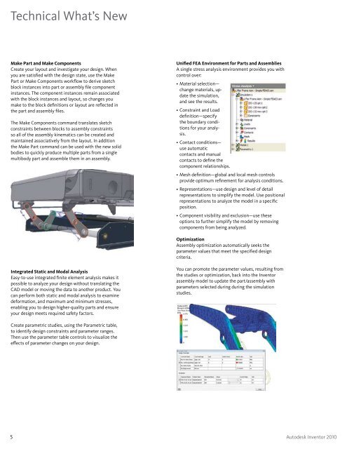
Technical What’s <strong>New</strong>Make Part and Make ComponentsCreate your layout and investigate your design. Whenyou are satisfied with the design state, use the MakePart or Make Components workflow to derive sketchblock instances into part or assembly file componentinstances. The component instances remain associatedwith the block instances and layout, so changes youmake to the block definitions or layout are reflected inthe part and assembly files.The Make Components command translates sketchconstraints between blocks to assembly constraintsso all of the assembly kinematics can be created andmaintained associatively from the layout. In additionthe Make Part command can be used with the new solidbodies to quickly produce multiple parts from a singlemultibody part and assemble them in an assembly.Unified FEA Environment for Parts and AssembliesA single stress analysis environment provides you withcontrol over:• Material selection—change materials, updatethe simulation,and see the results.• Constraint and Loaddefinition—specifythe boundary conditionsfor your analysis.• Contact conditions—use automaticcontacts and manualcontacts to define thecomponent relationships.• Mesh definition—global and local mesh controlsprovide optimum refinement for analysis conditions.• Representations—use design and level of detailrepresentations to simplify the model. Use positionalrepresentations to analyze the model in a specificposition.• Component visibility and exclusion—use theseoptions to further simplify the model by removingcomponents from being analyzed.OptimizationAssembly optimization automatically seeks theparameter values that meet the specified designcriteria.Integrated Static and Modal AnalysisEasy-to-use integrated finite element analysis makes itpossible to analyze your design without translating theCAD model or moving the data to another product. Youcan perform both static and modal analysis to examinedeformation, and maximum and minimum stresses,enabling you to design higher-quality parts and ensureyour design meets required safety factors.You can promote the parameter values, resulting fromthe studies or optimization, back into the <strong>Inventor</strong>assembly model to update the part/assembly withparameters selected during during the simulationstudies.Create parametric studies, using the Parametric table,to identify design constraints and parameter ranges.Then use the parameter table controls to visualize theeffects of parameter changes on your design.5 <strong>Autodesk</strong> <strong>Inventor</strong> <strong>2010</strong>