
You also want an ePaper? Increase the reach of your titles
YUMPU automatically turns print PDFs into web optimized ePapers that Google loves.
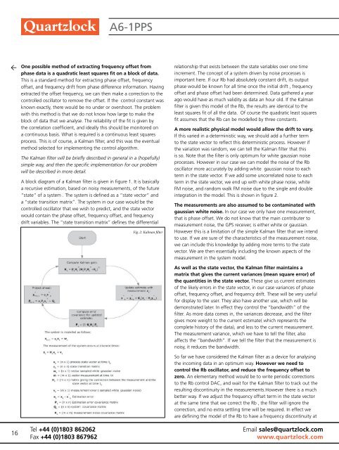
A6-1PPS16One possible method of extracting f<strong>re</strong>quency offset fromphase data is a quadratic least squa<strong>re</strong>s fit on a block of data.This is a standard method for extracting phase offset, f<strong>re</strong>quencyoffset, and f<strong>re</strong>quency drift from phase diffe<strong>re</strong>nce information. Havingextracted the offset f<strong>re</strong>quency, we can then make a cor<strong>re</strong>ction to thecontrolled oscillator to <strong>re</strong>move the offset. If the control constant wasknown exactly, the<strong>re</strong> would be no under or overshoot. The problemwith this method is that we do not know how large to make theblock of data that we analyse. The <strong>re</strong>liability of the fit is given bythe cor<strong>re</strong>lation coefficient, and ideally this should be monito<strong>re</strong>d ona continuous basis. What is <strong>re</strong>qui<strong>re</strong>d is a continuous least squa<strong>re</strong>sprocess. This is of course, a Kalman filter, and this was the eventualmethod selected for implementing the control algorithm.The Kalman filter will be briefly described in general in a (hopefully)simple way, and then the specific implementation for our problemwill be described in mo<strong>re</strong> detail.A block diagram of a Kalman filter is given in figu<strong>re</strong> 1. It is basicallya <strong>re</strong>cursive estimation, based on noisy measu<strong>re</strong>ments, of the futu<strong>re</strong>“state” of a system . The system is defined as a “state vector” anda “state transition matrix”. The system in our case would be thecontrolled oscillator that we wish to p<strong>re</strong>dict, and the state vectorwould contain the phase offset, f<strong>re</strong>quency offset, and f<strong>re</strong>quencydrift variables. The “state transition matrix” defines the diffe<strong>re</strong>ntialeconomical design. The basic ns clock to give a basic ±200 pstiming Tel <strong>re</strong>solution +44 is (0)1803 400 ns <strong>re</strong>solution. 862062(one processor cycle at a 10MHzclock f<strong>re</strong>quency). Fax +44 (0)1803A time867962interval expander mustbe calibrated as otherwise aThe time interval expander extendsthe <strong>re</strong>solution by 2000 the time error pulse rollsglitch will be produced whenoverFig. 2: Kalman filterond, the dead time is used tocalibrate the time expander. Thehardwa<strong>re</strong> generates exact pulsesof 100 ns and 500 ns by gatingfrom the 10 MHz clock. Thesea<strong>re</strong> expanded and measu<strong>re</strong>d. The<strong>re</strong>lationship that exists between the state variables over one timeinc<strong>re</strong>ment. The concept of a system driven by noise processes isimportant he<strong>re</strong>. If our Rb had absolutely constant drift, its outputphase would be known for all time once the initial drift , f<strong>re</strong>quencyoffset and phase offset had been determined. Data gathe<strong>re</strong>d a yearago would have as much validity as data an hour old. If the Kalmanfilter is given this model of the Rb, the <strong>re</strong>sults a<strong>re</strong> identical to theleast squa<strong>re</strong>s fit of all the data. Of course the quadratic least squa<strong>re</strong>sfit assumes that the Rb can be modelled by th<strong>re</strong>e constants.A mo<strong>re</strong> <strong>re</strong>alistic physical model would allow the drift to vary.If this varied in a deterministic way, we should add a further termto the state vector to <strong>re</strong>flect this deterministic process. However ifthe variation was random, we can tell the Kalman filter that thisis so. Note that the filter is only optimum for white gaussian noiseprocesses. However in our case we can model the noise of the Rboscillator mo<strong>re</strong> accurately by adding white gaussian noise to eachterm in the state vector. If we add some uncor<strong>re</strong>lated noise to eachterm in the state vector, we end up with white phase noise, whiteFM noise, and random walk FM noise due to the single and doubleintegration in the model. This is shown in figu<strong>re</strong> 2.The measu<strong>re</strong>ments a<strong>re</strong> also assumed to be contaminated withgaussian white noise. In our case we only have one measu<strong>re</strong>ment,that is phase offset. We do not know that the main contributer tomeasu<strong>re</strong>ment noise, the GPS <strong>re</strong>ceiver, is either white or gaussian.16 bit DACs a<strong>re</strong> used, with theoutput However of the fine this tune is a DAC limitation of the simple Kalman filter that we intenddivided by 256 and added tothe to output use. of If the we coarse a<strong>re</strong> su<strong>re</strong> tune of the characteristics of the measu<strong>re</strong>ment noise,DAC. we This can gives include effectively this 24 knowledge by adding mo<strong>re</strong> terms to the statebit <strong>re</strong>solution with an overlapbetween vector. the We coarse a<strong>re</strong> and then fine essentially including the known aspects of thetune measu<strong>re</strong>ment DACs. A softwa<strong>re</strong> in the nor-systemalisation process ensu<strong>re</strong>s thatmodel.the fine tune DAC is used fortuning As most well of as the the time. state Only vector, the Kalman filter maintains awhen matrix the controlled that gives oscillator the cur<strong>re</strong>nt variances (mean squa<strong>re</strong> error) ofhas drifted out of range of thefine the tune quantities DAC would the coarse in the state vector. These give us cur<strong>re</strong>nt estimatestune DAC need adjusting, withthe of chance the of likely a very small errors glitch in the state vector, in our case variances of phasein offset, the tuning f<strong>re</strong>quency voltage. A p<strong>re</strong>cision,low noise, voltage <strong>re</strong>fe<strong>re</strong>nceoffset, and f<strong>re</strong>quency drift. These will be very usefulis used for to display supply the to DACs. the user. They also have another use, which will beThe demonstrated microcontroller is provided later. In effect they control the “bandwidth” of thewith an RS232 interface. A simpleset of control codes enablefilter. As mo<strong>re</strong> data comes in, the variances dec<strong>re</strong>ase, and the filtermonitoring gives mo<strong>re</strong> and set weight up of the to the cur<strong>re</strong>nt estimate( which <strong>re</strong>p<strong>re</strong>sents thecontrolled oscillator parametersto complete accommodate history a wide range of the data), and less to the cur<strong>re</strong>nt measu<strong>re</strong>ment.of controlled The measu<strong>re</strong>ment oscillators. A Windowsfront end program will usevariance, which we have to tell the filter, alsothe affects control codes the to “bandwidth”. enable the If we tell the filter that the measu<strong>re</strong>ment isoperation of the PLL to be monito<strong>re</strong>dnoisy, with it <strong>re</strong>al <strong>re</strong>duces time graphs the of bandwidth.<strong>perf</strong>ormance measu<strong>re</strong>s.So far we have conside<strong>re</strong>d the Kalman filter as a device for analysingSoftwa<strong>re</strong> the incoming design data in an optimum way. However we need toIn control normal operation the Rb the oscillator, auto and <strong>re</strong>duce the f<strong>re</strong>quency offset tocalibration <strong>perf</strong>orms calibrationcycles zero. every An 20 ms. elementary The approximatetime of arrival of the nextmethod would be to write periodic cor<strong>re</strong>ctions1PPStoinputthe Rbpulsecontrolis known,DAC,soand wait for the Kalman filter to track out thethe <strong>re</strong>sulting calibration cycles discontinuity a<strong>re</strong> paused in the measu<strong>re</strong>ments.However the<strong>re</strong> is a muchwhile the 1PPS is measu<strong>re</strong>d. Theraw better measu<strong>re</strong>ment way. of If the we arrival adjust the f<strong>re</strong>quency offset term in the state vectortime at is the cor<strong>re</strong>cted same for time the actual that we cor<strong>re</strong>ct the Rb , the filter will igno<strong>re</strong> theexpansion ratio and is scaled tolie cor<strong>re</strong>ction, in the range -500.000000 and no to extra settling time will be <strong>re</strong>qui<strong>re</strong>d. In effect we+499999999 ns <strong>re</strong>lative to theinternal a<strong>re</strong> defining clock. the model of the Rb to have a f<strong>re</strong>quency discontinuity atTechnical featu<strong>re</strong> 19The first valid 1PPS edge to arriveafter <strong>re</strong>set is used to zero theinternal clock. This makes thearrival time initially close to zero,and avoids problems with lackof p<strong>re</strong>cision in the floating pointEmail sales@quartzlock.comwww.quartzlock.com