Low Level Measurements Handbook
Low Level Measurements Handbook
Low Level Measurements Handbook
- No tags were found...

Create successful ePaper yourself
Turn your PDF publications into a flip-book with our unique Google optimized e-Paper software.
www.keithley.comLLM6 th Edition<strong>Low</strong> <strong>Level</strong> <strong>Measurements</strong> <strong>Handbook</strong>Precision DC Current, Voltage, and Resistance <strong>Measurements</strong>
<strong>Low</strong> <strong>Level</strong><strong>Measurements</strong><strong>Handbook</strong>Precision DC Current, Voltage,and Resistance <strong>Measurements</strong>SIXTH EDITION
TABLE OF C ONTENTSSECTION 1 <strong>Low</strong> <strong>Level</strong> DC Measuring Instruments1.1 Introduction ..................................................................................1-31.2 Theoretical Measurement Limits..............................................1-31.3 Instrument Definitions................................................................1-51.3.1 The Electrometer..........................................................1-51.3.2 The DMM ......................................................................1-71.3.3 The Nanovoltmeter ......................................................1-71.3.4 The Picoammeter..........................................................1-81.3.5 The Source-Measure Unit ............................................1-81.3.6 The SourceMeter ® Instrument ....................................1-91.3.7 The <strong>Low</strong> Current Preamp ............................................1-91.3.8 The Micro-ohmmeter....................................................1-91.4 Understanding Instrument Specifications ..........................1-101.4.1 Definition of Accuracy Terms ....................................1-101.4.2 Accuracy......................................................................1-101.4.3 Deratings ....................................................................1-131.4.4 Noise and Noise Rejection ........................................1-141.4.5 Speed ..........................................................................1-151.5 Circuit Design Basics ................................................................1-161.5.1 Voltmeter Circuits ......................................................1-161.5.2 Ammeter Circuits........................................................1-171.5.3 Coulombmeter Circuits..............................................1-221.5.4 High Resistance Ohmmeter Circuits ..........................1-221.5.5 <strong>Low</strong> Resistance Ohmmeter Circuits ..........................1-251.5.6 Complete Instruments................................................1-29SECTION 2 <strong>Measurements</strong> from High Resistance Sources2.1 Introduction ..................................................................................2-22.2 Voltage <strong>Measurements</strong> fromHigh Resistance Sources ............................................................2-22.2.1 Loading Errors and Guarding ......................................2-22.2.2 Insulation Resistance..................................................2-11<strong>Low</strong> <strong>Level</strong> <strong>Measurements</strong> <strong>Handbook</strong>iii
2.3 <strong>Low</strong> Current <strong>Measurements</strong>....................................................2-142.3.1 Leakage Currents and Guarding ................................2-142.3.2 Noise and Source Impedance ....................................2-192.3.3 Zero Drift ....................................................................2-212.3.4 Generated Currents....................................................2-222.3.5 Voltage Burden ..........................................................2-282.3.6 Overload Protection ..................................................2-302.3.7 AC Interference and Damping ..................................2-312.3.8 Using a Coulombmeter to Measure <strong>Low</strong> Current......2-332.4 High Resistance <strong>Measurements</strong> ............................................2-362.4.1 Constant-Voltage Method ..........................................2-362.4.2 Constant-Current Method ..........................................2-372.4.3 Characteristics of High Ohmic Valued Resistors ........2-432.5 Charge <strong>Measurements</strong>..............................................................2-442.5.1 Error Sources..............................................................2-442.5.2 Zero Check ................................................................2-452.5.3 Extending the Charge Measurement Rangeof the Electrometer ....................................................2-462.6 General Electrometer Considerations ..................................2-472.6.1 Making Connections ..................................................2-472.6.2 Electrostatic Interference and Shielding....................2-492.6.3 Environmental Factors................................................2-522.6.4 Speed Considerations ................................................2-532.6.5 Johnson Noise ............................................................2-582.6.6 Device Connections....................................................2-622.6.7 Analog Outputs ..........................................................2-662.6.8 Floating Input Signals ................................................2-672.6.9 Electrometer Verification............................................2-68SECTION 3 <strong>Measurements</strong> from <strong>Low</strong> Resistance Sources3.1 Introduction ..................................................................................3-23.2 <strong>Low</strong> Voltage <strong>Measurements</strong> ......................................................3-23.2.1 Offset Voltages ..............................................................3-23.2.2 Noise ..........................................................................3-103.2.3 Common-Mode Current and Reversal Errors ............3-15iv
3.3 <strong>Low</strong> Resistance <strong>Measurements</strong>..............................................3-163.3.1 Lead Resistance and Four-Wire Method ....................3-163.3.2 Thermoelectric EMFs andOffset Compensation Methods ..................................3-193.3.3 Non-Ohmic Contacts ..................................................3-233.3.4 Device Heating ..........................................................3-243.3.5 Dry Circuit Testing......................................................3-253.3.6 Testing Inductive Devices ..........................................3-26SECTION 4 Applications4.1 Introduction ..................................................................................4-24.2 Applications for Measuring Voltagefrom High Resistance Sources..................................................4-24.2.1 Capacitor Dielectric Absorption ..................................4-24.2.2 Electrochemical <strong>Measurements</strong>....................................4-54.3 <strong>Low</strong> Current Measurement Applications ..............................4-94.3.1 Capacitor Leakage <strong>Measurements</strong>................................4-94.3.2 <strong>Low</strong> Current Semiconductor <strong>Measurements</strong> ............4-114.3.3 Light <strong>Measurements</strong> with Photomultiplier Tubes......4-144.3.4 Ion Beam <strong>Measurements</strong>............................................4-164.3.5 Avalanche Photodiode Reverse Bias Current<strong>Measurements</strong> ............................................................4-184.4 High Resistance Measurement Applications ......................4-204.4.1 Surface Insulation Resistance Testingof Printed Circuit Boards............................................4-204.4.2 Resistivity <strong>Measurements</strong> of Insulating Materials ......4-224.4.3 Resistivity <strong>Measurements</strong> of Semiconductors ............4-264.4.4 Voltage Coefficient Testing ofHigh Ohmic Value Resistors ......................................4-354.5 Charge Measurement Applications ......................................4-364.5.1 Capacitance <strong>Measurements</strong> ........................................4-374.5.2 Using a Faraday Cup to MeasureStatic Charge on Objects ............................................4-384.6 <strong>Low</strong> Voltage Measurement Applications ............................4-394.6.1 Standard Cell Comparisons........................................4-39<strong>Low</strong> <strong>Level</strong> <strong>Measurements</strong> <strong>Handbook</strong>v
4.6.2 High Resolution Temperature <strong>Measurements</strong>and Microcalorimetry ................................................4-424.7 <strong>Low</strong> Resistance Measurement Applications ......................4-444.7.1 Contact Resistance......................................................4-444.7.2 Superconductor Resistance <strong>Measurements</strong> ..............4-474.7.3 Resistivity <strong>Measurements</strong> of Conductive Materials ....4-50SECTION 5 <strong>Low</strong> <strong>Level</strong> Instrument Selection Guide5.1 Introduction ..................................................................................5-25.2 Instrument and Accessory Selector Guides ..........................5-2APPENDIX A <strong>Low</strong> <strong>Level</strong> Measurement Troubleshooting GuideAPPENDIX B Cable and Connector AssemblyAPPENDIX C GlossaryAPPENDIX D Safety ConsiderationsINDEXvi
SECTION 1<strong>Low</strong> <strong>Level</strong> DCMeasuringInstruments
FIGURE 1-1: Standard Symbols Used in this TextPrefixesSymbolyzafpnµm(none)kMGTPEZYPrefixyoctozeptoattofemtopiconanomicromilli-(none)kilomegagigaterapetaexazettayotta-Exponent10 –2410 –2110 –1810 –1510 –1210 –910 –610 –310 010 310 610 910 1210 1510 1810 2110 24SymbolVAΩCsWFHzKQuantitiesUnitvoltsamperesohmscoulombssecondswattsfaradscycles/sdegreesQuantityEMFcurrentresistancechargetimepowercapacitancefrequencytemperature1-2 SECTION 1
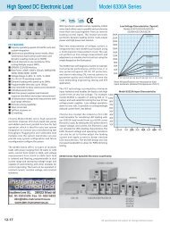
1.1 IntroductionDC voltage, DC current, and resistance are measured most often with digitalmultimeters (DMMs). Generally, these instruments are adequate formeasurements at signal levels greater than 1µV or 1µA, or less than 1GΩ.(See Figure 1-1 for standard symbols used in this text.) However, they don’tapproach the theoretical limits of sensitivity. For low level signals, more sensitiveinstruments such as electrometers, picoammeters, and nanovoltmetersmust be used.Section 1 offers an overview of the theoretical limits of DC measurementsand the instruments used to make them. It includes instrumentdescriptions and basic instrument circuit designs. For easier reference, thisinformation is organized into a number of subsections:1.2 Theoretical Measurement Limits: A discussion of both the theoreticalmeasurement limitations and instrument limitations for low level measurements.1.3 Instrument Definitions: Descriptions of electrometers, DMMs, nanovoltmeters,picoammeters, source-measure units, SourceMeter ® instruments,low current preamps, and micro-ohmmeters.1.4 Understanding Instrument Specifications: A review of the terminologyused in instrument specifications, such as accuracy (resolution, sensitivity,transfer stability), deratings (temperature coefficient, time drift),noise (NMRR and CMRR), and speed.1.5 Circuit Design Basics: Describes basic circuit design for voltmeter circuits(electrometer, nanovoltmeter) and ammeter circuits (shunt ammeter,feedback picoammeter, high speed picoammeter, logarithmicpicoammeter).1.2 Theoretical Measurement LimitsThe theoretical limit of sensitivity in any measurement is determined by thenoise generated by the resistances present in the circuit. As discussed inSections 2.6.5 and 3.2.2, voltage noise is proportional to the square root ofthe resistance, bandwidth, and absolute temperature. Figure 1-2 shows theoreticalvoltage measurement limits at room temperature (300K) with aresponse time of 0.1 second to ten seconds. Note that high source resistancelimits the theoretical sensitivity of the voltage measurement. While it’scertainly possible to measure a 1µV signal that has a 1Ω source resistance,it’s not possible to measure that same 1µV signal level from a 1TΩ source.Even with a much lower 1MΩ source resistance, a 1µV measurement is neartheoretical limits, so it would be very difficult to make using an ordinaryDMM.In addition to having insufficient voltage or current sensitivity (mostDMMs are no more sensitive than 1µV or 1nA per digit), DMMs have high<strong>Low</strong> <strong>Level</strong> DC Measuring Instruments 1-3
FIGURE 1-2: Theoretical Limits of Voltage <strong>Measurements</strong>1kV10 3NoiseVoltage1VWithin theoretical limits10 01mV1µV1nV1pVNear theoretical limitsProhibitedby noise10 –310 –610 –910 –1210 0 10 3 10 6 10 9 10 121Ω 1kΩ 1MΩ 1GΩ 1TΩSource Resistanceinput offset current 1 when measuring voltage and lower input resistancecompared to more sensitive instruments intended for low level DC measurements.These characteristics cause errors in the measurement; refer toSections 2 and 3 for further discussion of them.Given these DMM characteristics, it’s not possible to use a DMM tomeasure signals at levels close to theoretical measurement limits, as shownin Figure 1-3. However, if the source resistance is 1MΩ or less, or if thedesired resolution is no better than 0.1µV (with low source resistance), thesignal level isn’t “near theoretical limits,” and a DMM is adequate. If bettervoltage sensitivity is desired, and the source resistance is low (as it must bebecause of theoretical limitations), a nanovoltmeter provides a means ofmeasuring at levels much closer to the theoretical limits of measurement.With very high source resistance values (for example, 1TΩ), a DMM isn’t asuitable voltmeter. DMM input resistance ranges from 10MΩ to 10GΩ—severalorders of magnitude less than a 1TΩ source resistance, resulting insevere input loading errors. Also, input currents are typically manypicoamps, creating large voltage offsets. However, because of its much higherinput resistance, an electrometer can make voltage measurements at levelsthat approach theoretical limits. A similar situation exists for low levelcurrent measurements; DMMs generally have a high input voltage drop1Input current flows in the input lead of an active device or instrument. With voltage measurements, theinput current is ideally zero; thus, any input current represents an error. With current measurements, thesignal current becomes the input current of the measuring instrument. However, some background currentis always present when no signal current is applied to the instrument input. This unwanted currentis the input offset current (often called just the offset current) of the instrument.The source and test connections can also generate unwanted offset currents and offset voltages.A leakage current is another unwanted error current resulting from voltage across an undesired resistancepath (called leakage resistance). This current, combined with the offset current, is the total errorcurrent.1-4 SECTION 1
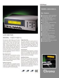
FIGURE 1-3: Typical Digital Multimeter (DMM), Nanovoltmeter (nVM), NanovoltPreamplifier (nV PreAmp), and Electrometer Limits of Measurement atVarious Source Resistances1V10 0NoiseVoltage1mV10 –3ElectrometerDMMnVMnV PreAmp1µV1nV10 –610 –91pV10 –31mΩ10 0 10 3 10 6 10 9 10 121Ω 1kΩ 1MΩ 1GΩ 1TΩSource Resistance10 151PΩ10 –12(input burden), which affects low level current measurements, and DMMresolution is generally no better than 1nA. Thus, an electrometer or picoammeterwith its much lower input burden and better sensitivity will operateat levels much closer to the theoretical (and practical) limits of low currentmeasurements.1.3 Instrument DefinitionsA number of different types of instruments are available to make DC measurements,including electrometers, DMMs, nanovoltmeters, picoammeters,SMUs (source-measure units), SourceMeter instruments, low current preamps,and micro-ohmmeters. The following paragraphs discuss and comparethe important characteristics of these instruments.1.3.1 The ElectrometerAn electrometer is a highly refined DC multimeter. As such, it can be usedfor many measurements performed by a conventional DC multimeter.Additionally, an electrometer’s special input characteristics and high sensitivityallow it to make voltage, current, resistance, and charge measurementsfar beyond the capabilities of a conventional DMM.An electrometer must be used when any of the following conditionsexist:1. The task requires an extended measurement range unavailable withconventional instruments, such as for detecting or measuring:• Currents less than 10nA (10 –8 A).• Resistances greater than 1GΩ (10 9 Ω).<strong>Low</strong> <strong>Level</strong> DC Measuring Instruments 1-5
2. Circuit loading must be minimized, such as when:• Measuring voltage from a source resistance of 100MΩ or higher.• Measuring current when input voltage drop (burden) of less than afew hundred millivolts is required (when measuring currents fromsources of a few volts or less).3. Charge measurement is required.4. Measuring signals at or near Johnson noise limitations (as indicated inFigure 1-2).In addition to their versatility, electrometers are easy to operate, reliable,and rugged.Voltmeter FunctionThe input resistance of an electrometer voltmeter is extremely high, typicallygreater than 100TΩ (10 14 Ω). Furthermore, the input offset current isless than 3fA (3×10 –15 A). These characteristics describe a device that canmeasure voltage with a very small amount of circuit loading.Because of the high input resistance and low offset current, the electrometervoltmeter has minimal effect on the circuit being measured. As aresult, the electrometer can be used to measure voltage in situations wherean ordinary multimeter would be unusable. For example, the electrometercan measure the voltage on a 500pF capacitor without significantly dischargingthe device; it can also measure the potential of piezoelectric crystalsand high impedance pH electrodes.Ammeter FunctionAs an ammeter, the electrometer is capable of measuring extremely low currents,limited only by theoretical limits or by the instrument’s input offsetcurrent. It also has a much lower voltage burden than conventional DMMs.With its extremely low input offset current and minimal input voltageburden, it can detect currents as low as 1fA (10 –15 A). Because of this highsensitivity, it’s suitable for measuring the current output of photomultipliersand ion chambers, as well as very low currents in semiconductors, massspectrometers, and other devices.Ohmmeter FunctionAn electrometer may measure resistance by using either a constant-currentor a constant-voltage method. If using the constant-current method, theelectrometer’s high input resistance and low offset current enables measurementsup to 200GΩ. When using the constant-voltage method, the electrometerapplies a constant voltage to the unknown resistance, measuresthe current, and then calculates the resistance. This is the preferred methodbecause it allows the unknown resistor to be tested at a known voltage. Anelectrometer can measure resistances up to 10PΩ (10 16 Ω) using thismethod.1-6 SECTION 1
Coulombmeter FunctionCurrent integration and measurement of charge are electrometer coulombmetercapabilities not found in multimeters. The electrometer coulombmetercan detect charge as low as 10fC (10 –14 C). It’s equivalent to an activeintegrator and, therefore, has low voltage burden, typically less than 100µV.The coulombmeter function can measure lower currents than theammeter function can, because no noise is contributed by internal resistors.Currents as low as 1fA (10 –15 A) may be detected using this function. SeeSection 2.3.8 for further details.1.3.2 The DMMDigital multimeters vary widely in performance, from low cost handheld 3 1 ⁄2-digit units to high precision system DMMs. While there are many modelsavailable from a wide variety of manufacturers, none approaches the theoreticallimits of measurement discussed previously. These limitations don’timply that DMMs are inadequate instruments; they simply point out the factthat the vast majority of measurements are made at levels far from theoreticallimits, and DMMs are designed to meet these more conventional measurementneeds.Although low level measurements are by definition those that are closeto theoretical limits, and are thus outside the range of DMMs, advances intechnology are narrowing the gap between DMMs and dedicated low levelinstruments. For example, the most sensitive DMMs can detect DC voltagesas low as 10nV, resolve DC currents down to 10pA, and measure resistancesas high as 1GΩ. While these characteristics still fall far short of the correspondingcapabilities of more sensitive instruments like the electrometerdescribed previously, all the measurement theory and accuracy considerationsin this book apply to DMM measurements as well as to nanovoltmeter,picoammeter, electrometer, or SMU measurements. The difference is only amatter of degree; when making measurements close to theoretical limits, allmeasurement considerations are vitally important. When measuring at levelsfar from theoretical limits, only a few basic considerations (accuracy,loading, etc.) are generally of concern.1.3.3 The NanovoltmeterA nanovoltmeter is a very sensitive voltage meter. As shown in Figure 1-3,this type of instrument is optimized to provide voltage measurements nearthe theoretical limits from low source resistances, in contrast to the electrometer,which is optimized for use with high source resistances.Compared to an electrometer, the voltage noise and drift are much lower,and the current noise and drift are much higher. Input resistance is usuallysimilar to that of a DMM and is much lower than that of an electrometer.As is the case with electrometers, nanovoltmeters are just as reliable andeasy to operate as DMMs. Their distinguishing characteristic is their voltagesensitivity, which can be as good as 1pV. Most nanovoltmeters aren’t multi-<strong>Low</strong> <strong>Level</strong> DC Measuring Instruments 1-7
function instruments and are correspondingly less complex thanelectrometers.1.3.4 The PicoammeterA picoammeter is an ammeter built along the lines of the ammeter functionof an electrometer. When compared with an electrometer, a picoammeterhas a similar low voltage burden, similar or faster speed, less sensitivity, anda lower price. It may also have special characteristics, such as high speedlogarithmic response or a built-in voltage source.1.3.5 The Source-Measure UnitAs its name implies, a source-measure unit (SMU) has both measuring andsourcing capabilities. Adding current and voltage sourcing capabilities to ameasuring instrument provides an extra degree of versatility for many lowlevel measurement applications. For example, very high resistance valuescan be determined by applying a voltage across a device and measuring theresulting current. The added sourcing functions also make a SMU more convenientand versatile than using separate instruments for such applicationsas generating I-V curves of semiconductors and other types of devices.The typical SMU provides the following four functions:• Measure voltage• Measure current• Source voltage• Source currentThese functions can be used separately or they can be used together inthe following combinations:• Simultaneously source voltage and measure current, or• Simultaneously source current and measure voltage.SMUs have a number of electrometer-like characteristics that makethem suitable for low level measurements. The input resistance is very high(typically 100TΩ or more), minimizing circuit loading when making voltagemeasurements from high impedance sources. The current measurementsensitivity is also similar to that of the electrometer picoammeter—typicallyas low as 10fA.Another important advantage of many source-measure units is theirsweep capability. Either voltage or current can be swept across the desiredrange at specified increments, and the resulting current or voltage can bemeasured at each step. Built-in source-delay-measure cycles allow optimizingmeasurement speed while ensuring sufficient circuit settling time tomaintain measurement integrity.1-8 SECTION 1
1.3.6 The SourceMeter ® InstrumentThe SourceMeter instrument is very similar to the source-measure unit inmany ways, including its ability to source and measure both current andvoltage and to perform sweeps. In addition, a SourceMeter instrument candisplay the measurements directly in resistance, as well as voltage andcurrent.The typical SourceMeter instrument doesn’t have as high an inputimpedance or as low a current capability as a source-measure unit. TheSourceMeter instrument is designed for general-purpose, high speed productiontest applications. It can be used as a source for moderate to lowlevel measurements and for research applications.Unlike a DMM, which can make a measurement at only one point, aSourceMeter instrument can be used to generate a family of curves, becauseit has a built-in source. This is especially useful when studying semiconductordevices and making materials measurements.When used as a current source, a SourceMeter instrument can be usedin conjunction with a nanovoltmeter to measure very low resistances byautomatically reversing the polarity of the source to correct for offsets.1.3.7 The <strong>Low</strong> Current PreampSome SMUs and SourceMeter instruments may have a remote low currentpreamp. With this design, the sensitive amplifier circuitry is separate fromthe SMU or SourceMeter instrument. This makes it possible to place themost sensitive part of the instrument very close to the device being tested,thereby eliminating a major source of error, the noise and leakage from thecables themselves.1.3.8 The Micro-ohmmeterA micro-ohmmeter is a special type of ohmmeter designed especially formaking low level resistance measurements. While the techniques used formaking resistance measurements are similar to those used in a DMM, microohmmetercircuits are optimized for making low level measurements. Thetypical micro-ohmmeter can resolve resistances as low as 10µΩ.<strong>Measurements</strong> made using the micro-ohmmeter are always performedusing the four-wire technique in order to minimize errors caused by testleads and connections. The typical micro-ohmmeter also has additional featuressuch as offset compensation and dry circuit testing to optimize lowresistance measurements. Offset compensation is performed by pulsing thetest current to cancel offsets from thermoelectric EMFs. The dry circuit testmode limits the voltage across the unknown resistance to a very small value(typically
1.4 Understanding Instrument SpecificationsKnowing how to interpret instrument specifications properly is an importantaspect of making good low level measurements. Although instrumentaccuracy is probably the most important of these specifications, there areseveral other factors to consider when reviewing specifications, includingnoise, deratings, and speed.1.4.1 Definition of Accuracy TermsThis section defines a number of terms related to instrument accuracy.Some of these terms are further discussed in subsequent paragraphs. Table1-1 summarizes conversion factors for various specifications associated withinstruments.SENSITIVITY - the smallest change in the signal that can be detected.RESOLUTION - the smallest portion of the signal that can be observed.REPEATABILITY - the closeness of agreement between successive measurementscarried out under the same conditions.REPRODUCIBILITY - the closeness of agreement between measurements ofthe same quantity carried out with a stated change in conditions.ABSOLUTE ACCURACY - the closeness of agreement between the result of ameasurement and its true value or accepted standard value. Accuracyis often separated into gain and offset terms.RELATIVE ACCURACY - the extent to which a measurement accuratelyreflects the relationship between an unknown and a reference value.ERROR - the deviation (difference or ratio) of a measurement from its truevalue. Note that true values are by their nature indeterminate.RANDOM ERROR - the mean of a large number of measurements influencedby random error matches the true value.SYSTEMATIC ERROR - the mean of a large number of measurements influencedby systematic error deviates from the true value.UNCERTAINTY - an estimate of the possible error in a measurement, i.e., theestimated possible deviation from its actual value. This is the oppositeof accuracy.“Precision” is a more qualitative term than many of those defined here.It refers to the freedom from uncertainty in the measurement. It’s oftenapplied in the context of repeatability or reproducibility, but it shouldn’t beused in place of “accuracy.”1.4.2 AccuracyOne of the most important considerations in any measurement situation isreading accuracy. For any given test setup, a number of factors can affectaccuracy. The most important factor is the accuracy of the instrument itself,which may be specified in several ways, including a percentage of full scale,1-10 SECTION 1
TABLE 1-1: Specification Conversion FactorsNumber of timePercent PPM Digits Bits dBPortionof 10Vconstants to settleto rated accuracy10% 100000 1 3.3 –20 1 V 2.31% 10000 2 6.6 –40 100mV 4.60.1% 1000 3 10 –60 10mV 6.90.01% 100 4 13.3 –80 1mV 9.20.001% 10 5 16.6 –100 100 µV 11.50.0001% 1 6 19.9 –120 10 µV 13.80.00001% 0.1 7 23.3 –140 1µV 16.10.000001% 0.01 8 26.6 –160 100 nV 18.40.000001% 0.001 9 29.9 –180 10 nV 20.7a percentage of reading, or a combination of both. Instrument accuracyaspects are covered in the following paragraphs.Other factors such as input loading, leakage resistance and current,shielding, and guarding may also have a serious impact on overall accuracy.These important measurement considerations are discussed in detail inSections 2 and 3.Measurement Instrument SpecificationsInstrument accuracy is usually specified as a percent of reading, plus a percentageof range (or a number of counts of the least significant digit). Forexample, a typical DMM accuracy specification may be stated as: ±(0.005%of reading + 0.002% of range). Note that the percent of reading is most significantwhen the reading is close to full scale, while the percent of range ismost significant when the reading is a small fraction of full scale.Accuracy may also be specified in ppm (parts per million). Typically, thisaccuracy specification is given as ±(ppm of reading + ppm of range). Forexample, the DCV accuracy of a higher resolution DMM might be specifiedas ±(25ppm of reading + 5ppm of range).ResolutionThe resolution of a digital instrument is determined by the number ofcounts that can be displayed, which depends on the number of digits. A typicaldigital electrometer might have 5 1 ⁄2 digits, meaning five whole digits(each with possible values between 0 and 9) plus a leading half digit thatcan take on the values 0 or ±1. Thus, a 5 1 ⁄2-digit display can show 0 to199,999, a total of 200,000 counts. The resolution of the display is the ratioof the smallest count to the maximum count (1/200,000 or 0.0005% for a5 1 ⁄2-digit display).<strong>Low</strong> <strong>Level</strong> DC Measuring Instruments 1-11
For example, the specification of ±(0.05% + 1 count) on a 4 1 ⁄2-digitmeter reading 10.000 volts corresponds to a total error of ±(5mV + 1mV)out of 10V, or ±(0.05% of reading + 0.01% of reading), totaling ±0.06%.Generally, the higher the resolution, the better the accuracy.SensitivityThe sensitivity of a measurement is the smallest change of the measured signalthat can be detected. For example, voltage sensitivity may be 1µV, whichsimply means that any change in input signal less than 1µV won’t show upin the reading. Similarly, a current sensitivity of 10fA implies that onlychanges in current greater than that value will be detected.The ultimate sensitivity of a measuring instrument depends on both itsresolution and the lowest measurement range. For example, the sensitivityof a 5 1 ⁄2-digit DMM with a 200mV measurement range is 1µV.Absolute and Relative AccuracyAs shown in Figure 1-4, absolute accuracy is the measure of instrumentaccuracy that is directly traceable to the primary standard at the NationalInstitute of Standards and Technology (NIST). Absolute accuracy may bespecified as ±(% of reading + counts), or it can be stated as ±(ppm of reading+ ppm of range), where ppm signifies parts per million of error.FIGURE 1-4: Comparison of Absolute and Relative AccuracyNISTStandardSecondaryStandardAbsoluteAccuracyMeasuringInstrumentRelativeAccuracyDeviceUnder TestRelative accuracy (see Figure 1-4) specifies instrument accuracy tosome secondary reference standard. As with absolute accuracy, relative accuracycan be specified as ±(% of reading + counts) or it may be stated as±(ppm of reading + ppm of range).1-12 SECTION 1
Transfer StabilityA special case of relative accuracy is the transfer stability, which definesinstrument accuracy relative to a secondary reference standard over a veryshort time span and narrow ambient temperature range (typically withinfive minutes and ±1°C). The transfer stability specification is useful in situationswhere highly accurate measurements must be made in reference to aknown secondary standard.Calculating Error Terms from Accuracy SpecificationsTo illustrate how to calculate measurement errors from instrument specifications,assume the following measurement parameters:Accuracy: ±(25ppm of reading + 5ppm of range)Range: 2VInput signal: 1.5VThe error is calculated as:Error = 1.5(25 × 10 –6 ) + 2(5 × 10 –6 )= (37.5 × 10 –6 ) + (10 × 10 –6 )= 47.5 × 10 –6Thus, the reading could fall anywhere within the range of 1.5V ±47.5µV, an error of ±0.003%.1.4.3 DeratingsAccuracy specifications are subject to deratings for temperature and timedrift, as discussed in the following paragraphs.Temperature CoefficientThe temperature of the operating environment can affect accuracy. For thisreason, instrument specifications are usually given over a defined temperaturerange. Keithley accuracy specifications on newer electrometers, nanovoltmeters,DMMs, and SMUs are usually given over the range of 18°C to28°C. For temperatures outside of this range, a temperature coefficient suchas ±(0.005 % + 0.1 count)/°C or ±(5ppm of reading + 1ppm of range)/°Cis specified. As with the accuracy specification, this value is given as a percentageof reading plus a number of counts of the least significant digit (oras a ppm of reading plus ppm of range) for digital instruments. If the instrumentis operated outside the 18°C to 28°C temperature range, this figuremust be taken into account, and errors can be calculated in the mannerdescribed previously for every degree less than 18°C or greater than 28°C.Time DriftMost electronic instruments, including electrometers, picoammeters, nanovoltmeters,DMMs, SMUs, and SourceMeter instruments, are subject tochanges in accuracy and other parameters over a long period of time,whether or not the equipment is operating. Because of these changes,instrument specifications usually include a time period beyond which the<strong>Low</strong> <strong>Level</strong> DC Measuring Instruments 1-13
instrument’s accuracy cannot be guaranteed. The time period is stated inthe specifications, and is typically over specific increments such as 90 daysor one year. As noted previously, transfer stability specifications are definedfor a much shorter period of time—typically five or 10 minutes.1.4.4 Noise and Noise RejectionNoise is often a consideration when making virtually any type of electronicmeasurement, but noise problems can be particularly severe when makinglow level measurements. Thus, it’s important that noise specifications andterms are well understood when evaluating the performance of an instrument.Normal Mode Rejection RatioNormal mode rejection ratio (NMRR) defines how well the instrumentrejects or attenuates noise that appears between the HI and LO input terminals.Noise rejection is accomplished by using the integrating A/D converterto attenuate noise at specific frequencies (usually 50 and 60Hz) whilepassing low frequency or DC normal mode signals. As shown in Figure1-5, normal mode noise is an error signal that adds to the desired inputsignal. Normal mode noise is detected as a peak noise or deviation in a DCsignal. The ratio is calculated as:peak normal mode noiseNMRR = 20 log _______________________________[ peak measurement deviation ]FIGURE 1-5: Normal Mode NoiseMeasuringInstrumentHILONoiseSignalNormal mode noise can seriously affect measurements unless steps aretaken to minimize the amount added to the desired signal. Careful shieldingwill usually attenuate normal mode noise, and many instruments haveinternal filtering to reduce the effects of such noise even further.Common Mode Rejection RatioCommon mode rejection ratio (CMRR) specifies how well an instrumentrejects noise signals that appear between both input high and input low andchassis ground, as shown in Figure 1-6. CMRR is usually measured with a1kΩ resistor imbalance in one of the input leads.1-14 SECTION 1
FIGURE 1-6: Common Mode NoiseMeasuringInstrumentHILOR imbalanceSignal(usually 1kΩ)NoiseAlthough the effects of common mode noise are usually less severe thannormal mode noise, this type of noise can still be a factor in sensitive measurementsituations. To minimize common mode noise, connect shieldsonly to a single point in the test system.Noise SpecificationsBoth NMRR and CMRR are generally specified in dB at 50 and 60Hz, whichare the interference frequencies of greatest interest. (CMRR is often specifiedat DC as well.) Typical values for NMRR and CMRR are >80dB and>120dB respectively.Each 20dB increase in noise rejection ratio reduces noise voltage or currentby a factor of 10. For example, a rejection ratio of 80dB indicates noisereduction by a factor of 10 4 , while a ratio of 120dB shows that the commonmode noise would be reduced by a factor of 10 6 . Thus, a 1V noise signalwould be reduced to 100µV with an 80dB rejection ratio and down to 1µVwith a 120dB rejection ratio.1.4.5 SpeedInstrument measurement speed is often important in many test situations.When specified, measurement speed is usually stated as a specific numberof readings per second for given instrument operating conditions. Certainfactors such as integration period and the amount of filtering may affectoverall instrument measurement speed. However, changing these operatingmodes may also alter resolution and accuracy, so there is often a tradeoffbetween measurement speed and accuracy.Instrument speed is most often a consideration when making lowimpedance measurements. At higher impedance levels, circuit settling timesbecome more important and are usually the overriding factor in determiningoverall measurement speed. Section 2.6.4 discusses circuit settling timeconsiderations in more detail.<strong>Low</strong> <strong>Level</strong> DC Measuring Instruments 1-15
1.5 Circuit Design BasicsCircuits used in the design of many low level measuring instruments,whether a voltmeter, ammeter, ohmmeter, or coulombmeter, generally usecircuits that can be understood as operational amplifiers. Figure 1-7 showsa basic operational amplifier. The output voltage is given by:V O = A (V 1 – V 2 )FIGURE 1-7: Basic Operational AmplifierV 1+–V 2AV OCOMMONV O = A (V 1 – V 2 )The gain (A) of the amplifier is very large, a minimum of 10 4 to 10 5 , andoften 10 6 . The amplifier has a power supply (not shown) referenced to thecommon lead.Current into the op amp inputs is ideally zero. The effect of feedbackproperly applied is to reduce the input voltage difference (V 1 – V 2 ) to zero.1.5.1 Voltmeter CircuitsElectrometer VoltmeterThe operational amplifier becomes a voltage amplifier when connected asshown in Figure 1-8. The offset current is low, so the current flowingthrough R A and R B is the same. Assuming the gain (A) is very high, the voltagegain of the circuit is defined as:V O = V 2 (1 + R A /R B )Thus, the output voltage (V O ) is determined both by the input voltage(V 2 ), and amplifier gain set by resistors R A and R B . Given that V 2 is appliedto the amplifier input lead, the high input resistance of the operationalamplifier is the only load on V 2 , and the only current drawn from the sourceis the very low input offset current of the operational amplifier. In manyelectrometer voltmeters, R A is shorted and R B is open, resulting inunity gain.1-16 SECTION 1
FIGURE 1-8: Voltage Amplifier+–V 2AR AV OV 1R BV O = V 2 (1 + R A /R B )Nanovoltmeter PreamplifierThe same basic circuit configuration shown in Figure 1-8 can be used as aninput preamplifier for a nanovoltmeter. Much higher voltage gain isrequired, so the values of R A and R B are set accordingly; a typical voltagegain for a nanovoltmeter preamplifier is 10 3 .Electrometer and nanovoltmeter characteristics differ, so the operationalamplifier requirements for these two types of instruments are alsosomewhat different. While the most important characteristics of the electrometervoltmeter operational amplifier are low input offset current andhigh input impedance, the most important requirement for the nanovoltmeterinput preamplifier is low input noise voltage.1.5.2 Ammeter CircuitsThere are two basic techniques for making current measurements: these arethe shunt ammeter and the feedback ammeter techniques. DMMs and olderelectrometers use the shunt method, while picoammeters and the AMPSfunction of electrometers use the feedback ammeter configuration only.Shunt AmmeterShunting the input of a voltmeter with a resistor forms a shunt ammeter, asshown in Figure 1-9. The input current (I IN ) flows through the shunt resistor(R S ). The output voltage is defined as:V O = I IN R S (1 + R A /R B )For several reasons, it’s generally advantageous to use the smallest possiblevalue for R S .First, low value resistors have better accuracy, time and temperature stability,and voltage coefficient than high value resistors. Second, lower resistor<strong>Low</strong> <strong>Level</strong> DC Measuring Instruments 1-17
values reduce the input time constant and result in faster instrumentresponse time. To minimize circuit loading, the input resistance (R S ) of anammeter should be small, thus reducing the voltage burden (V 2 ). However,note that reducing the shunt resistance will degrade the signal-to-noise ratio.FIGURE 1-9: Shunt AmmeterR SI INV O = I IN R S (1 + R A /R B )V 2+–AR AV OV 1R BFeedback AmmeterIn this configuration, shown in Figure 1-10, the input current (I IN ) flowsthrough the feedback resistor (R F ). The low offset current of the amplifier(A) changes the current (I IN ) by a negligible amount. The amplifier outputvoltage is calculated as:V O = –I IN R FThus, the output voltage is a measure of input current, and overall sensitivityis determined by the feedback resistor (R F ). The low voltage burden(V 1 ) and corresponding fast rise time are achieved by the high gain op amp,which forces V 1 to be nearly zero.FIGURE 1-10: Feedback AmmeterR FI INInput+V 1–AV OOutputV O = –I IN R F1-18 SECTION 1
Picoammeter amplifier gain can be changed as in the voltmeter circuitby using the combination shown in Figure 1-11. Here, the addition of R Aand R B forms a “multiplier,” and the output voltage is defined as:V O = –I IN R F (1 + R A /R B )FIGURE 1-11: Feedback Ammeter with Selectable Voltage GainI INR FV O = –I IN R F (1 + R A /R B )–+V 1AR AV OR BHigh Speed PicoammeterThe rise time of a feedback picoammeter is normally limited by the timeconstant of the feedback resistor (R F ) and any shunting capacitance (C F ). Abasic approach to high speed measurements is to minimize stray shuntingcapacitance through careful mechanical design of the picoammeter.Remaining shunt capacitance can be effectively neutralized by a slightmodification of the feedback loop, as shown in Figure 1-12. If the time constantR 1 C 1 is made equal to the time constant R F C F , the shaded area of thecircuit behaves exactly as a resistance R F with zero C F . The matching of timeconstants in this case is fairly straightforward, because the capacitancesinvolved are all constant and aren’t affected by input capacitances.Logarithmic PicoammeterA logarithmic picoammeter can be formed by replacing the feedback resistorin a picoammeter with a diode or transistor exhibiting a logarithmic voltage-currentrelationship, as shown in Figure 1-13. The output voltage (andthe meter display) is then equal to the logarithm of the input current. As aresult, several decades of current can be read on the meter without changingthe feedback element.<strong>Low</strong> <strong>Level</strong> DC Measuring Instruments 1-19
FIGURE 1-12: Neutralizing Shunt CapacitanceC FR 1C 1–AI IN +FIGURE 1-13: Logarithmic Picoammeter–AI IN +R FV OV OThe main advantage of a logarithmic picoammeter is its ability to followcurrent changes over several decades without range changing.The big disadvantage is the loss of accuracy and resolution, but somedigital picoammeters combine accuracy and dynamic range by combiningautoranging and digital log conversion.If two diodes are connected in parallel, back-to-back, this circuit willfunction with input signals of either polarity.1-20 SECTION 1
Using a small-signal transistor in place of a diode produces somewhatbetter performance. Figure 1-14 shows an NPN transistor and a PNP transistorin the feedback path to provide dual polarity operation.FIGURE 1-14: Dual Polarity Log Current to Voltage Converter1000pFInput–+AOutputRemote Preamp Circuit (Source V, Measure I Mode)Figure 1-15 illustrates a typical preamp circuit. In the Source V, Measure Imode, the SMU applies a programmed voltage and measures the currentflowing from the voltage source. The sensitive input is surrounded by aguard, which can be carried right up to the DUT for fully guarded measurements.The remote preamp amplifies the low current signal passing throughthe DUT; therefore, the cable connecting the remote preamp to the measurementmainframe carries only high level signals, minimizing the impact ofcable noise.FIGURE 1-15: Remote Preamp in Source V, Measure I ModeTomeasurementmainframe ofSMU orSourceMeterAI INGuardLOAI INInput/OutputHITo DUT<strong>Low</strong> <strong>Level</strong> DC Measuring Instruments 1-21
1.5.3 Coulombmeter CircuitThe coulombmeter measures electrical charge that has been stored in acapacitor or that might be produced by some charge generating process.For a charged capacitor, Q = CV, where Q is the charge in coulombs onthe capacitor, C is the capacitance in farads, and V is the potential across thecapacitor in volts. Using this relationship, the basic charge measuringscheme is to transfer the charge to be measured to a capacitor of knownvalue and then measure the voltage across the known capacitor; thus,Q = CV.The electrometer is ideal for charge measurements, because the low offsetcurrent won’t alter the transferred charge during short time intervalsand the high input resistance won’t allow the charge to bleed away.Electrometers use a feedback circuit to measure charge, as shown inFigure 1-16. The input capacitance of this configuration is AC F . Thus, largeeffective values of input capacitance are obtained using reasonably sizedcapacitors for C F .FIGURE 1-16: Feedback CoulombmeterC F–+AV O1.5.4 High Resistance Ohmmeter CircuitsElectrometer Picoammeter and Voltage SourceIn this configuration (Figure 1-17), a voltage source (V S ) is placed in serieswith an unknown resistor (R X ) and an electrometer picoammeter. The voltagedrop across the picoammeter is small, so essentially all the voltageappears across R X , and the unknown resistance can be computed from thesourced voltage and the measured current (I).The advantages of this method are that it’s fast and, depending on thepower supply voltage and insulating materials, it allows measuring extremelyhigh resistance. Also, with an adjustable voltage source, the voltagedependence of the resistance under test can be obtained directly.1-22 SECTION 1
FIGURE 1-17: High Resistance Measurement Using External Voltage SourceR XR X = V SIHIV S ILOElectrometerPicoammeterElectrometer Ohmmeter Using Built-In Current SourceFIGURE 1-18: Electrometer Ohmmeter with Built-In Current SourceBuilt-In Current SourceV SI = V S /RV 1 = IR XUsually, this method requires two instruments: a voltage source and apicoammeter or electrometer. Some electrometers and picoammeters, however,have a built-in voltage source and are capable of measuring the resistancedirectly.Figure 1-18 shows the basic configuration of an alternative form of electrometerohmmeter. A built-in constant-current source, formed by V S and R,forces a known current through the unknown resistance (R X ). The resultingvoltage drop is proportional to the unknown resistance and is indicated bythe meter as resistance, rather than voltage.RI–+AR X C S V 1V O<strong>Low</strong> <strong>Level</strong> DC Measuring Instruments 1-23
The disadvantage of this method is that the voltage across the unknownis a function of its resistance, so it cannot be easily controlled. Very highresistances tend to have large voltage coefficients; therefore, measurementsmade with a constant voltage are more meaningful. In addition, theresponse speed for resistances greater than 10GΩ will be rather slow. Thislimitation can be partially overcome by guarding.Electrometer Ohmmeter with Guarded Ohms ModeFigure 1-19 shows a modification of the circuit in Figure 1-18 in which theHI input node is surrounded with a guard voltage from the operationalamplifier output. The amplifier has unity gain, so this guard voltage is virtuallythe same potential as V 1 and the capacitance (C S ) of the input cable islargely neutralized, resulting in much faster measurements of resistancesgreater than 10GΩ.FIGURE 1-19: Electrometer Ohmmeter with Guarded OhmsBuilt-In Current SourceV SI = V S /RV 1 = IR XRI–A+R X C S GuardV 1V OThe guarded mode also significantly reduces the effect of input cableleakage resistance, as discussed in Section 2.4.2.Electrometer Voltmeter and External Current SourceIn this method, shown in Figure 1-20, a current source generates current(I), which flows through the unknown resistor (R X ). The resulting voltagedrop is measured with an electrometer voltmeter, and the value of R X is calculatedfrom the voltage and current.1-24 SECTION 1
FIGURE 1-20: High Resistance Measurement Using External Current Source withElectrometer VoltmeterExternalCurrentSourceI R X V 1HILOElectrometerVoltmeterV 1 = I R XIf the current source has a buffered ×1 output, a low impedance voltmeter,such as a DMM, may be used to read the voltage across R X . Thisarrangement is shown in Figure 1-21.FIGURE 1-21: High Resistance Measurement Using a True Current Source witha DMM–A+HI×1 OutputI R X V 1V OLODMMConstant-Current Sourcewith Buffered ×1 OutputV O≈ V 1 = IR X1.5.5 <strong>Low</strong> Resistance Ohmmeter CircuitsNanovoltmeter and External Current SourceIf the electrometer in Figure 1-20 is replaced with a nanovoltmeter, the circuitcan be used to measure very low resistances (
DMM OhmmeterThe typical DMM uses the ratiometric technique shown in Figure 1-22 tomake resistance measurements. When the resistance function is selected, aseries circuit is formed between the ohms voltage source, a reference resistance(R REF ), and the resistance being measured (R X ). The voltage causes acurrent to flow through the two resistors. This current is common to bothresistances, so the value of the unknown resistance can be determined bymeasuring the voltage across the reference resistance and across theunknown resistance and calculating as:SENSE HI – SENSE LOR X = R REF · __________________________REF HI – REF LOFIGURE 1-22: Ratiometric Resistance MeasurementRef HIR REFR SV REFR 1Input HIRef LOR XR 2Four-wireconnectiononlyR 3Sense HISense LOV SENSESense HISense LOR SR 4Input LOR X = R REFV SENSEV REFR 1 , R 2 , R 3 , R 4 = lead resistanceThe resistors (R S ) provide automatic two-wire or four-wire resistancemeasurements. When used in the two-wire mode, the measurement willinclude the lead resistance, represented by R 1 and R 4 . When the unknownresistance is low, perhaps less than 100Ω, the four-wire mode will give muchbetter accuracy. The sense lead resistance, R 2 and R 3 , won’t cause significanterror because the sense circuit has very high impedance.1-26 SECTION 1
Micro-ohmmeterThe micro-ohmmeter also uses the four-wire ratiometric technique, whichis shown in Figure 1-23. It doesn’t have the internal resistors (R S ), as in theDMM, so all four leads must be connected to make a measurement. Also,the terminals that supply test current to the unknown resistance are labeledSource HI and Source LO.FIGURE 1-23: Micro-ohmmeter Resistance MeasurementRef HIR REFSource HIV REFR 1Ref LOR XR 2Sense HIV SENSESense HIR 3Sense LOSense LOR 4Source LOR X = R REF · VSENSEV REFThe pulsed drive mode, shown in Figure 1-24, allows the microohmmeterto cancel stray offset voltages in the unknown resistance beingmeasured. During the measurement cycle, the voltage across the unknownresistance is measured twice, once with the drive voltage on, and a secondtime with the drive voltage turned off. Any voltage present when the drivevoltage is off represents an offset voltage and will be subtracted from thevoltage measured when the drive voltage is on, providing a more accuratemeasurement of the resistance.The dry circuit test mode, shown in Figure 1-25, adds a resistor acrossthe source terminals to limit the open-circuit voltage to less than 20mV. Thisprevents breakdown of any insulating film in the device being tested andgives a better indication of device performance with low level signals. Themeter must now measure the voltage across this resistor (R SH ), as well as thevoltage across the reference resistor and the unknown resistor. See Section3.3.5 for more information on dry circuit testing.<strong>Low</strong> <strong>Level</strong> DC Measuring Instruments 1-27
FIGURE 1-24:Micro-ohmmeter in Pulse ModeRef HIR REF V REFR 1 Source HIRef LO S 1R 2 Sense HISense HIR X V X V SENSEV OSR 3 Sense LOSense LOR 4Source LOR X = R REF · VSENSE 1 – V SENSE 2V REFwhere V SENSE 1 is measured with S 1 closed, and is equal to V X + V OS , andV SENSE 2 is measured with S 1 open, and is equal to V OS .FIGURE 1-25:Micro-ohmmeter with Dry Circuit OnRef HIR REFV REFR 1Source HIRef LOSense HIR 2Sense HIShunt HIR XV SENSER SHV SHR 3Sense LOShunt LOSense LOR 4Source LOR X =V SENSEV REF V SHR REFR SH1-28 SECTION 1
FIGURE 1-26: Typical Digital ElectrometerAmpsCoulombsFunction/RangeDigital Multimeters (DMMs)Most DMMs include five measurement functions: DC volts, AC volts, ohms,DC amps, and AC amps. As shown in Figure 1-27, various signal processingcircuits are used to convert the input signal into a DC voltage that can beconverted to digital information by the A/D converter.The DC and AC attenuator circuits provide ranging for the AC and DCfunctions. The AC converter changes AC signals to DC, while the ohms con-MicroprocessorDisplayIEEE-488InterfaceVoltsOhmsA/DConverterInputHILOZeroCheck–A+RangingAmplifier2V AnalogOutputPreampOutputVolts, OhmsGuardOutputAmps, Coulombs1.5.6 Complete InstrumentsDigital ElectrometersFigure 1-26 is a block diagram of a typical digital electrometer. The analogsection is similar to the circuitry discussed previously. An electrometer preamplifieris used at the input to increase sensitivity and raise input resistance.The output of the main amplifier is applied to both the analog outputand the A/D converter. Range switching and function switching, instead ofbeing performed directly, are controlled by the microprocessor.The microprocessor also controls the A/D converter and supervises allother operating aspects of the instrument. The input signal to the A/D converteris generally 0–2V DC. After conversion, the digital data is sent to thedisplay and to the digital output port (IEEE- 488 or RS-232).<strong>Low</strong> <strong>Level</strong> DC Measuring Instruments 1-29
FIGURE 1-27: DMM Block DiagramACAttenuatorACConverterDigitalDisplayHIINPUTAmpsACDCOhmsDCAttenuatorOhmsConverterACDCOhmsA/DConverterPrecisionReferenceDigitalOutputPorts(IEEE-488,RS-232,Ethernet)PrecisionShuntsLOverter provides a DC analog signal for resistance measurements. Precisionshunts are used to convert currents to voltages for the amps functions.Once the input signal is appropriately processed, it’s converted to digitalinformation by the A/D converter. Digital data is then sent to the displayand to the digital output port (IEEE-488, RS-232, or Ethernet).NanovoltmetersA nanovoltmeter is a sensitive voltmeter optimized to measure very low voltages.As shown in Figure 1-28, the nanovoltmeter incorporates a low noisepreamplifier, which amplifies the signal to a level suitable for A/D conversion(typically 2–3V full scale). Specially designed preamplifier circuitsensure that unwanted noise, thermoelectric EMFs, and offsets are kept to anabsolute minimum.FIGURE 1-28: Typical NanovoltmeterHIDCV InputLO<strong>Low</strong>-NoisePreamplifierRangeSwitchingA/DConverterDisplayIEEE-488,RS-232OffsetCompensationMicroprocessor1-30 SECTION 1
In order to cancel internal offsets, an offset or drift compensation circuitallows the preamplifier offset voltage to be measured during specificphases of the measurement cycle. The resulting offset voltage is subsequentlysubtracted from the measured signal to maximize measurementaccuracy.Once the preamplifier amplifies the signal, it’s converted to digitalinformation by the A/D converter. Digital data is then sent to the display andthe IEEE-488 interface.SMUsThe SMU provides four functions in one instrument: measure voltage, measurecurrent, source voltage and source current. Generally, such instrumentscan simultaneously source voltage and measure current or simultaneouslysource current and measure voltage.When configured to Source I and Measure V (as shown in Figure 1-29),the SMU will function as a high impedance current source with voltagemeasure (and voltage limit) capability.Selecting either local or remote sense determines where the voltagemeasurement will be made. In local sense, the voltage is measured at theoutput of the SMU. In remote sense, the voltage is measured at the deviceunder test, eliminating any voltage drops due to lead resistance.The driven guard (×1 Buffer) ensures that the Guard and Output HI terminalsare always at the same potential. Proper use of Guard virtually eliminatesleakage paths in the cable, test fixture, and connectors. When configuredto Source V and Measure I (as shown in Figure 1-30), the SMU willfunction as a low impedance voltage source with current measure (and currentlimit) capability.SourceMeter InstrumentLike an SMU, a SourceMeter instrument can source current, source voltage,measure current and measure voltage. However, the SourceMeter instrumentalso has a sixth terminal, guard sense, which allows making moreaccurate measurements of networks. When configured to source current asshown in Figure 1-31, the SourceMeter unit functions as a high impedancecurrent source with voltage limit capability and it can measure current, voltage,or resistance.For voltage measurements, the sense selection (two-wire local or fourwireremote) determines where the measurement is made. In local sense,voltage is measured at the IN/OUT terminals of the instrument. In four-wireremote sense, voltage is measured directly at the device under test using theSense terminals. This eliminates any voltage drops due to lead resistance.When configured to source voltage as shown in Figure 1-32, theSourceMeter instrument functions as a low impedance voltage source withcurrent limit capability and it can measure current, voltage, or resistance.<strong>Low</strong> <strong>Level</strong> DC Measuring Instruments 1-31
FIGURE 1-29: Source I Mode of SMU×1BufferGuardOutput HIGuardLocalRemoteSense HIGuardI SourceV MeterRemoteLocalSense LOOutput LOOutput LOFIGURE 1-30: Source V Mode of SMUI MeterOutput HIGuardLocalRemoteSense HIV SourceMeasur eOutputAdjustV Source(Feedback)V MeterRemoteGuardSense LOLocalOutput LOOutput LO1-32 SECTION 1
Sense circuitry is used to monitor the output voltage continuously andadjust the V Source as needed.FIGURE 1-31: Source I Mode of a SourceMeter Instrument+×1 Guard–Guard SenseI MeterIn/Out HILocalRemoteSense HII SourceV MeterRemoteSense LOLocalIn/Out LOFIGURE 1-32: Source V Mode of a SourceMeter Instrument+–GuardGuard SenseI MeterIn/Out HILocalRemoteSense HIV SourceSenseOutputAdjustV Source(Feedback)V MeterRemoteSense LOLocalIn/Out LO<strong>Low</strong> <strong>Level</strong> DC Measuring Instruments 1-33
SECTION 2<strong>Measurements</strong> fromHigh ResistanceSources
2.1 IntroductionAs described in Section 1 of this handbook, measurements made from highresistance sources include low DC voltage, low DC current, high resistance,and charge measurements. The instruments used to make these highimpedance measurements include electrometers, picoammeters, andsource-measure units (SMUs). While Section 1 described the basic circuitsof these instruments and their measurement functions, Section 2 offersmore detailed information about these functions, various interferences anderror sources, and ways to maximize the accuracy of measurements madefrom high resistance sources. For easier reference, the information inSection 2 is organized into these subsections:2.2 High Impedance Voltage <strong>Measurements</strong>: A discussion of loading errorsand the use of guarding to minimize these errors, as well as informationon insulating materials used for making high impedance measurements.2.3 <strong>Low</strong> Current <strong>Measurements</strong>: Information about making successful lowcurrent measurements is described with such topics as leakage currentand guarding, noise and source impedance, zero drift, generated currents,voltage burden, overload protection, and using a coulombmeterto measure low current.2.4 High Resistance <strong>Measurements</strong>: Describes the constant-voltage andconstant-current methods for measuring high resistance. It alsoincludes information on high valued resistors.2.5 Charge <strong>Measurements</strong>: A discussion of the error sources and ways tominimize them, zero check, and extending the range of the charge function.2.6 General Electrometer Considerations: A discussion of techniques anderror sources that affect high impedance measurements in general.Some of the topics include measurement connections, electrostaticinterference and shielding, environmental factors, speed considerations,etc.2.2 Voltage <strong>Measurements</strong> from High Resistance Sources<strong>Measurements</strong> from voltage sources with high internal resistance are subjectto a number of errors, such as loading errors from the voltmeter’s inputresistance and input bias current, as well as from external shunt resistanceand capacitance. The following paragraphs discuss these error sources andways to minimize their effects. For a discussion of errors due to improperconnections and electrostatic interference, see Section 2.6.2.2.1 Loading Errors and GuardingInput Resistance LoadingVoltage measurements from high resistance sources are subject to loadingerrors from the meter input resistance, as well as the leakage resistance of2-2 SECTION 2
the connecting cable. A practical voltmeter may be represented by an idealinfinite input-resistance voltmeter (V M ) in parallel with a resistor equal tothe specified input resistance (R IN ), as shown in Figure 2-1. When a sourcewhose Thevenin equivalent is V S in series with R S is connected to the input,the voltage (V M ) appearing across the meter input terminals is reduced bythe voltage divider action of R S and R IN as follows:RV INM = V S ––––––––––( RS + R IN)For example, assume R S = 100kΩ and R IN = 10MΩ. If V S = 5V, the actualvoltage measured by the meter is:10V 7M = 5 –––––––––––V M = 4.95V( 105 + 10 7 )Thus, input resistance loading would result in an error of 1% in thisexample.The meter input resistance should be much higher than the sourceresistance. For example, if the desired accuracy is 1%, then the meter resistancemust be more than 100 times the source resistance. For higher accuracy,this ratio must be correspondingly higher.The connecting cable ordinarily isn’t a factor, but with very high sourceresistances (>10GΩ) or under extreme environmental conditions, it canFIGURE 2-1: Effects of Input Resistance Loading on Voltage Measurement AccuracyHIR SV SR INInputResistanceV MLOVoltage SourceVoltmeter Measuring V SIndicating V MV M = V SR INR IN + R S<strong>Measurements</strong> from High Resistance Sources 2-3
cause significant loading errors. It may be possible to guard the cable andthus reduce its loading on the measurement. This is discussed in the paragraphson Shunt Resistance Loading and Guarding.Input Bias Current LoadingAnother consideration when measuring voltages from high resistancesources is the input bias current of the voltmeter. The input bias currentflows at the instrument input due to internal instrument circuitry and theinternal bias voltage. As shown in Figure 2-2, the input bias current (I BIAS )develops an error voltage across the source resistance (R S ). Thus, the actualmeasured voltage (V M ) differs from the source voltage (V S ) as follows:V M = V S ±I OFFSET R SFor example, assume the following parameters:I OFFSET = 1pA R S = 10GΩ V S = 10VThe actual voltage measured by the meter is:V M = 10 ± (10 –12 · 10 10 )V M = 10 ± 0.01V M = 9.99V or 10.01V (depending on the offset current polarity)Thus, the error caused by input offset current would be about 0.1% inthis example.Figure 2-2: Effects of Input Bias Current on Voltage Measurement AccuracyHIR SI BIASInputBiasCurrentV MV SLOVoltage SourceVoltmeter Measuring V SIndicating V MV M = V S – I BIAS R SDMMs and nanovoltmeters have bias currents from 1pA to 1nA, althoughDMM bias currents are not always specified. Electrometers are2-4 SECTION 2
known for their low input bias current, which is usually a few femtoamps.Picoammeters and SMUs also have very low input bias currents, althoughusually not as low as an electrometer’s.Although input bias current is a common source of this type of error,currents generated by external circuits can also result in errors due to voltagedrops across the source resistance. Typical sources of such offset currentsare insulators and cables.Shunt Resistance Loading and GuardingExternal shunt resistances, such as leaky cables and dirty insulators, mayalso cause loading errors.Any external shunt resistance across the voltage source will attenuatethe measured voltage, as shown in Figure 2-3. As in the case of input resistancevoltage loading, the shunt resistance (R SHUNT ) and the source resistance(R S ) form a voltage divider that reduces the measured voltage (V M ) asfollows:R SHUNTV M = V S ––––––––––––––( RSHUNT + R S)For example, assume R S = 10GΩ and R SHUNT = 100GΩ. If V S has a valueof 10V, the measured voltage (V M ) is:10V 11M = 10( 10)–––––––––––– 1011+ 10V M = 9.09VIn this instance, the error due to shunt loading is approximately 9%.FIGURE 2-3: Effects of Shunt Resistance on Voltage Measurement AccuracyHIR SV SShuntResistanceR SHUNTV MLOVoltage SourceVoltmeter Measuring V SIndicating V MR SHUNTV M = V S R S + R SHUNT<strong>Measurements</strong> from High Resistance Sources 2-5
Cable leakage resistance is a common source of shunt resistance loading,as shown in Figure 2-4. In this case, the measured voltage (V M ) is attenuatedby the voltage divider formed by R S and the cable resistance (R L ):( RS + R L)R LV M = V S –––––––––To reduce errors due to shunt resistance, use cables, connectors, andtest fixturing with the highest possible insulation resistance. In addition, theuse of guarding will eliminate any residual errors.FIGURE 2-4: Effect of Cable Leakage Resistance on Voltage Measurement AccuracyConnecting CableR SR LCableShieldHIV SCableLeakageResistanceV MLOVoltage SourceVoltmeter Measuring V SIndicating V MV M = V SR LR S + R LThe error due to cable leakage can be greatly reduced by the use ofguarding, as shown in Figure 2-5. In the guarded configuration, the cableshield is now connected to the output of the guard buffer instead of themeter LO terminal. R G represents the resistance from the cable shield tometer LO, and I G is the current through R G as a result of driving the shieldto the same potential as the input HI terminal. This current is supplied bythe guard buffer, not the voltage source. Since the voltage across R L is nowmany decades lower, the leakage current will be negligible in most cases.By definition, a guard is a low impedance point in the circuit that’s atnearly the same potential as the high impedance input terminal.In modern electrometers, the preamplifier output terminal is such apoint, and can be used to reduce the effect of cable leakage, as shown inFigure 2-5. An additional benefit is that the effective cable capacitance is2-6 SECTION 2
FIGURE 2-5: Guarded ConfigurationConnecting CableR SV SHICableShieldR LGUARDR G I GV M+A GUARD–LOVoltage SourceVoltmeter with Guard Bufferalso reduced, making the response speed of the circuit much faster. This isdiscussed in detail in the paragraphs on Shunt Capacitance Loading andGuarding.The source-measure unit (SMU) can also be used to measure voltagesfrom a high resistance source and the Guard terminal will make a similarimprovement.The circuit of the electrometer when used as a voltmeter is actually asshown in Figure 2-6. The guard amplifier is a unity-gain amplifier with veryhigh input impedance. The open-loop gain, A GUARD , ranges from 10 4 to 10 6 .The leakage resistance (R L ) is multiplied by this gain and the measured voltagebecomes:A GUARD RV LM = V S –––––––––––––––––( RS + A GUARD R L)Example: Assume R S has a value of 10GΩ and R L is 100GΩ. If we assumea mid-range value of 10 5 for A GUARD and a value of 10V for V S , the voltagemeasured by the meter is:10V 16M = 10 ––––––––––––––––––V M = 9.99999V( 1.000001 × 10¹⁶ )Thus, we see the loading error with guarding is less than 0.001%. Incontrast, the unguarded error voltage with this combination of source andshunt resistances would be about 9%.Shunt Capacitance Loading and GuardingThe settling time of a voltage measurement depends both on the equivalentsource resistance and the effective capacitance at the input of the voltmeter;<strong>Measurements</strong> from High Resistance Sources 2-7
FIGURE 2-6: Guarding Leakage ResistanceHI+R SR LV MA GUARD–GUARDV SLOVoltage SourceVoltmeter with Guard BufferA GUARD = 10 4 to 10 6V M = V SA GUARD R LR S + A GUARD R LFIGURE 2-7: Shunt Capacitance LoadingHIQ INR SV SShuntCapacitanceC SHUNTV MLOVoltage SourceVoltmeterV M = V S (1 – e –t/R SC SHUNT )Q IN = V S C SHUNT2-8 SECTION 2
this input capacitance consists of the meter input capacitance in parallelwith the input cable capacitance. Even a small amount of shunt capacitancecan result in long settling times if the source resistance is high. For example,a shunt capacitance of 100pF (including the input cable) and a sourceresistance of 20GΩ will result in an RC time constant of two seconds. Tenseconds must be allowed for the measurement to settle to within 1% of thefinal value.Figure 2-7 demonstrates the effects of shunt capacitance loading on theinput of a typical high impedance voltmeter. The signal source is representedby V S and R S , the shunt capacitance is C SHUNT , and the measured voltageis V M . Initially, the switch is open, and C SHUNT holds zero charge.When the switch is closed, the source voltage (V S ) is applied to theinput, but the measured voltage across C SHUNT doesn’t rise instantaneouslyto its final value. Instead, the voltage rises exponentially as follows:V M = V S (1 – e t/RSCSHUNT )Also, the charge (Q IN ) transferred to the capacitor is:Q IN = V S C SHUNTThe charging of C SHUNT yields the familiar exponential curve shown inFigure 2-8. After one time constant (τ = RC), the measured voltage rises towithin 63% of its final value; final values for various time constants are summarizedin Table 2-1.FIGURE 2-8: Exponential Response of Voltage Across Shunt Capacitance10090807063 6050Percent of 40Final Value 30(V S ) 20100Time0 1.0 2.0 3.0 4.0 5.0R S C SHUNTTABLE 2-1: Settling Times to Percent of Final ValueTime Constant (τ*) Percent of Final Value1 63 %2 86 %3 95 %4 98 %5 99.3 %*τ = RC, where R = resistance (ohms), C = capacitance (farads)<strong>Measurements</strong> from High Resistance Sources 2-9
Example: Assume R S = 10GΩ and C SHUNT = 100pF. This combinationresults in an RC time constant of one second. Thus, it would take five secondsfor the circuit to settle to within less than 1% of final value. With a 10Vchange in V S , a total of 1nC of charge would be transferred to C SHUNT .While the primary advantage of guarding is a reduction in the effects ofshunt resistance, another important aspect is the reduction in the effects ofshunt capacitance. As shown in Figure 2-9, the guard buffer significantlyreduces the charging time of C SHUNT because of the open-loop gain(A GUARD ), which is typically 10 4 to 10 6 .With guarding, the rise time of the measured voltage (V M ) nowbecomes:V M = V S (1 – e –tAGUARD/RSCSHUNT )and the charge transferred to C SHUNT is:V S CQ SHUNTIN = –––––––––––( AGUARD )Example: Assume R S = 10GΩ and C SHUNT = 100pF, as in the unguardedexample given previously. With a nominal value of 10 5 for A GUARD , we cansee the guarded RC settling time is reduced to approximately 5s/10 5 = 50µs,an insignificant period of time compared to the time it typically takes aninstrument to process a single reading. Note that with a 10V change in V S ,the charge transferred (Q IN ) is only 10fC, a reduction of 10 5 :1.FIGURE 2-9: Guarding Shunt CapacitanceR SV SVoltage SourceHI+A GUARD–C SHUNT V MGUARDLOVoltmeter with Guard BufferA GUARD = 10 4 to 10 6V M = V S (1 – e –tA GUARD/R S C SHUNT)C SHUNTQ IN = V S A GUARD2-10 SECTION 2
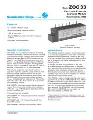
2.2.2 Insulation ResistanceElectrometers and some SMUs as voltmeters are characterized by high inputresistance. High resistance insulation in the test circuits is one of the firstrequirements of making successful electrometer measurements. Thus, aknowledge of the various types of insulating materials and how to applythem properly is important. To measure voltages from high resistancesources accurately, the insulation leakage resistance of the test fixtures, testleads, and measuring voltmeter must be several orders of magnitude higherthan the Thevenin equivalent resistance of the circuit under test, dependingon the number of decades of precision, resolution, or accuracyrequired. If the insulation resistances aren’t decades higher, the shuntingeffects of the insulation will reduce the source voltage being measured, asdiscussed previously.Detecting inferior insulation in test setups is difficult because the erroneousreading can appear well-behaved and steady. Therefore, it’s prudentto measure the insulation resistance of the test fixtures and cables periodicallywith an electrometer ohmmeter to ensure their integrity. If deficienciesare discovered, either cleaning or replacement of the defective insulator isin order.Choosing the Best InsulatorIn evaluating an insulating material, consider these material properties:• Volume resistivity: leakage of current directly through the material.• Surface resistivity: leakage across the surface, a function primarilyof surface contaminants.• Water absorption: leakage dependent on the amount of water thathas been absorbed by the insulator.• Piezoelectric or stored charge effects: the creation of chargeunbalances (and thus current flow or voltage shift) due to mechanicalstress.• Triboelectric effects: the creation of charge unbalance due to frictionaleffects when materials rub against each other.• Dielectric absorption: the tendency of an insulator to store/releasecharge over long periods.Table 2-2 summarizes important characteristics of insulators, whileFigure 2-10 shows their resistivity ranges. Insulator characteristics aredescribed further in the following paragraphs.Teflon ®Teflon is the most satisfactory and commonly used insulator for the impedancelevels encountered in measurements of currents greater than 10 –14 A.It has high volume resistivity and water vapor films don’t form readily on itssurface. Its insulating properties, therefore, aren’t severely impaired byhumid air. Teflon is chemically inert, is easily machined, and can be readily<strong>Measurements</strong> from High Resistance Sources 2-11
MaterialTABLE 2-2: Properties of Various Insulating MaterialsVolumeResistivity(Ohm-cm)________________________________ PROPERTY________________________________Resistanceto WaterAbsorptionMinimalPiezoelectricEffects 1MinimalTriboelectricEffectsMinimalDielectricAbsorptionSapphire >10 18 + + 0 +Teflon ® PTFE >10 18 + – – +Polyethylene 10 16 0 + 0 +Polystyrene >10 16 0 0 – +Kel-F ® >10 18 + 0 – 0Ceramic 10 14 –10 15 – 0 + +Nylon 10 13 –10 14 – 0 – –Glass Epoxy 10 13 – 0 – –PVC 5 × 10 13 + 0 0 –KEY: + Material very good in regard to the property.0 Material moderately good in regard to the property.– Material weak in regard to the property.1Stored charge effects in non-piezoelectric insulators.FIGURE 2-10: Approximate Resistivity of Various Insulating Materials10 18Volume Resistivity (Ω-cm)10 1710 1610 1510 1410 1310 1210 1110 1010 9FR-4EpoxyBoardPaperTeflonCeramicsNylonPVCSapphirePolystyrenePolyethylene10 8 Insulating Material2-12 SECTION 2
cleaned. Teflon PTFE is the type of Teflon most commonly used in electronics.Teflon’s principal shortcoming is that charges appear internally whenit’s deformed, causing spurious voltages and currents. With ordinary care,however, these characteristics aren’t serious for currents greater than10 –13 A.PolystyrenePolystyrene is much less expensive than Teflon, and was the general purposestandard before Teflon was available. It machines easily, but internalcrazing often develops. This characteristic doesn’t impair its insulatingproperties unless the cracks reach the surface. The volume resistivity ofpolystyrene is similar to that of Teflon, but water vapor films form on its surfacewhen humidity becomes high, significantly reducing its surfaceresistance.Kel-F ®Kel-F has volume and surface characteristics nearly as good as Teflon, itmachines easily, and it doesn’t craze.PolyethylenePolyethylene has excellent volume resistivity and surface characteristics similarto polystyrene. Because it’s flexible, it’s used extensively for insulatingcoaxial and triaxial cable. These cables are excellent for general-purposeelectrometer work because the surface leakage in this application is relativelyunimportant. However, polyethylene melts at a relatively low temperature,so leads into ovens should use Teflon insulation rather than polyethylene.Glass and CeramicsGlass and ceramics also have high volume resistivity, but poor surface propertiesat high humidity and often-poor piezoelectric properties. Glass orceramic cleaned with methanol and dipped in boiling paraffin has a good,but not durable, insulating surface. Various silicone varnishes can also bebaked or air-dried onto glass or ceramic surfaces, but even after this treatment,handling can easily spoil the insulators. Glass and ceramics are difficultto machine, although they can be molded. They are used principallywhen their mechanical properties are mandatory.SapphireSapphire is one of the best insulators. Very little charge is generated in itwhen it’s stressed mechanically. It’s used most often in measuring currentsin the 10 –18 A to 10 –15 A range. The use of sapphire is restricted by its cost andbecause the material is difficult to machine and form.<strong>Measurements</strong> from High Resistance Sources 2-13
QuartzQuartz has properties similar to sapphire, but considerably higher piezoelectricoutput, so it’s rarely used in electrometer circuits.Other Insulating MaterialsPractically all other insulating materials have unacceptably low volumeresistivity or unsatisfactory surface characteristics for electrometer use.Vinyl, nylon, and Lucite ® are markedly inferior to Teflon, polystyrene, polyethylene,sapphire, or quartz.Keeping Insulators CleanAs with any high resistance device, mishandling can destroy the integrity ofinsulators. Oils and salts from the skin can degrade insulator performance,and contaminants in the air can be deposited on the insulator surface,reducing its resistance. Therefore, insulator handling should be minimized;under no circumstances should the insulator be touched with the hand orwith any material that might contaminate the surface.If the insulator becomes contaminated, either through careless handlingor from deposits, it can be cleaned with a foam tipped swab dipped inmethanol. After cleaning, the insulator should be allowed to dry for severalhours at low humidity before use or be dried using dry nitrogen.2.3 <strong>Low</strong> Current <strong>Measurements</strong>A number of error sources can have serious impacts on low current measurementaccuracy. For example, the ammeter may cause measurementerrors if not connected properly. (Refer to Sections 2.6.1 and 2.6.2 for moreinformation on how to make properly shielded connections.) The ammeter’svoltage burden and input offset current may also affect measurementaccuracy. The source resistance of the device under test will affect the noiseperformance of a feedback ammeter. External sources of error can includeleakage current from cables and fixtures, as well as currents generated bytriboelectric or piezoelectric effects. Section 2.3 addresses low currentmeasurement considerations in detail and outlines methods for minimizingthe effects of error sources. It also includes information on using the electrometer’scoulomb function to make very low current measurements.2.3.1 Leakage Currents and GuardingLeakage currents are generated by stray resistance paths between the measurementcircuit and nearby voltage sources. These currents can degrade theaccuracy of low current measurements considerably. To reduce leakage currents,use good quality insulators, reduce the level of humidity in the testenvironment, and use guarding. Guarding will also reduce the effect ofshunt capacitance in the measurement circuit.Using good quality insulators when building the test circuit is one wayto reduce leakage currents. Teflon, polyethylene, and sapphire are examples2-14 SECTION 2
of good quality insulators, but avoid materials like phenolics and nylon.Refer to Section 2.2.2 for further discussion on choosing the best insulatingmaterials.Humidity may also degrade low current measurements. Different typesof insulators will absorb varying amounts of water from the air, so it’s bestto choose an insulator on which water vapor doesn’t readily form a continuousfilm. Sometimes, this is unavoidable if the material being measuredabsorbs water easily, so it’s best to make the measurements in an environmentallycontrolled room. In some cases, an insulator may have ioniccontaminants, which can generate a spurious current, especially in highhumidity.Guarding is a very effective way to reduce leakage currents. A guard is alow impedance point in the circuit that’s at nearly the same potential as thehigh impedance lead being guarded. The guard on the electrometer ammeterand picoammeter differs from the guard on the SMU ammeter. The useof guarding can best be explained through examples.The Use of Guarding Using an Electrometer Ammeter orPicoammeterThe guard terminal of the electrometer ammeter or picoammeter is the LOinput terminal. The guard can be used to isolate the high impedance inputlead of the ammeter from leakage current due to voltage sources. Figures2-11 and 2-12 illustrate examples of guarding.Figure 2-11 illustrates guarding as applied to measuring the ion current(I C ) from an ionization chamber. An unguarded ionization chamberand the corresponding equivalent circuit are shown in Figure 2-11a. Theequivalent circuit shows that the full bias voltage appears across the insulatorleakage resistance (R L ), therefore, a leakage current (I L ) will be added tothe measured ion current (I M = I C + I L ). The leakage resistance is due tothe insulator of the ionization chamber and the coax cable.In Figure 2-11b, a metal guard ring is added to the ionization chamber.This guard circuit splits the leakage resistance into two parts. The voltageacross R L1 is the picoammeter voltage burden, normally less than one millivolt,so the resulting current will be quite small. The full bias voltageappears across R L2 . A leakage current will flow around this loop, but won’taffect the measurement.Guarding may also be necessary to prevent leakage current due to testfixturing. Figure 2-12 shows a high mega-ohm resistor (R DUT ) supported ontwo insulators mounted in a metal test fixture.Figure 2-12a is the unguarded circuit. The leakage current (I L ) throughthe stand-off insulators will be added to the measured current (I M ).As illustrated in Figure 2-12b, this circuit is guarded by connecting theLO of the picoammeter (I M ) to the metal mounting plate. This will put thebottom of the right insulator at almost the same potential as the top. The<strong>Measurements</strong> from High Resistance Sources 2-15
FIGURE 2-11: Guarding as Applied to an Ionization Chambera) Unguarded Ionization Chamber Equivalent CircuitI M = I C + I LHIHII MI MLOI CR LI LLOb) Guarded Ionization Chamber Equivalent CircuitI M = I CHIHIR L1I MR L2I MGuardConnectionLOI CGuardI LLOvoltage difference is equal to the voltage burden of the picoammeter. Thevoltage burden is small, less than 200µV. The top and bottom of the insulatorare at nearly the same potential, so no significant current will flowthrough it, and nearly all the current from the device under test will flowthrough the ammeter as desired.The Use of Guarding with an SMU AmmeterThe guard terminal of an SMU is usually the inside shield of the triax connector.This guard is driven by a unity-gain, low impedance amplifier. Bydefinition, the guard terminal is nearly at the same potential as the highimpedance terminal, so the guard terminal will be at the same potential asthe magnitude of the voltage source.Figure 2-13 illustrates how a driven guard prevents the leakage resistanceof a cable from degrading the low current measurements. In theunguarded circuit of Figure 2-13a, the leakage resistance of the coax cable2-16 SECTION 2
FIGURE 2-12: Guarding to Reduce Leakage Currentsa) Unguarded CircuitMetal Shielded Test FixtureI DUTI M = I DUT + I LStandoffR DUTVHIR LI LR LHII MLOLOMetal Mounting PlateConnection forElectrostatic Shieldingb) Guarded CircuitMetal Shielded Test FixtureI DUTI M = I DUTStandoffR DUTVHILOR LR LI LMetal Mounting Plate0VHII MLOShield Connection(LO Terminal toMetal Shield ofTest Fixture)Guard Connection(LO Terminal toMetal MountingPlate)is in parallel with the DUT (R DUT ), creating an unwanted leakage current(I L ). This leakage current will degrade very low current measurements.In the guarded circuit shown in Figure 2-13b, the inside shield of thetriax cable is connected to the guard terminal of the SMU. Now this shieldis driven by a unity-gain, low impedance amplifier (Guard). The difference<strong>Measurements</strong> from High Resistance Sources 2-17
FIGURE 2-13: Guarding the Leakage Resistance of a Cable with an SMUa) Unguarded CircuitForce/Output HII DUTI M×1GuardZI LR LCoaxCableR DUTVForce/Output LOSMUR L = Coax Cable Leakage ResistanceI L = Leakage CurrentR DUT = Resistance of Device Under TestI M =I DUT + I Lb) Guarded CircuitForce/Output HII DUTI M×1GuardZ0VR L1TriaxCableR DUTVR L2Force/Output LOSMUR L1 = Triax Cable Inside Shield Leakage ResistanceR L2 = Leakage Resistance Between ShieldsR DUT = Resistance of Device Under TestI M =I DUTin potential between the Force/Output HI terminal and the Guard terminalis nearly 0V, so the leakage current (I L ) is eliminated.Figure 2-14 shows how the guard can eliminate the leakage currentthat may flow through the stand-off insulators in a test fixture. In Figure2-14a, leakage current (I L ) flows through the stand-off insulators (R L ). This2-18 SECTION 2
FIGURE 2-14: Test Fixture Guarding with an SMUa) Unguarded CircuitMetal Shielded Test FixtureForce/Output HII DUTI M = I DUT + I LI MV×1GuardZStandoffInsulatorsR DUTR L R LI LMetal Mounting PlateForce/Output LOSMUb) Guarded CircuitMetal Shielded Test FixtureForce/Output HII DUTI M = I DUTR DUTI MV×1GuardZ0VR L R LI L = 0Metal Mounting PlateForce/Output LOSMUleakage current is added to the current from the DUT (I DUT ) and is measuredby the SMU ammeter (I M ), adversely affecting the accuracy of the lowcurrent measurement.In Figure 2-14b, the metal mounting plate is connected to the guardterminal of the SMU. The voltages at the top and the bottom of the standoffinsulator are nearly at the same potential (0V drop), so no leakage currentwill flow through the standoffs and affect the measurement accuracy.For safety purposes, the metal shield must be connected to earth groundbecause the metal mounting plate will be at the guard potential.2.3.2 Noise and Source ImpedanceNoise can seriously affect sensitive current measurements. This section discusseshow source resistance and source capacitance affect noise performance.<strong>Measurements</strong> from High Resistance Sources 2-19
FIGURE 2-15: Simplified Model of a Feedback AmmeterZ FC FZ SR FC SV SR S–+V NOISEV OCurrent SourceFeedback AmmeterSource ResistanceThe source resistance of the DUT will affect the noise performance of a feedbackammeter. As the source resistance is reduced, the noise gain of theammeter will increase.Figure 2-15 shows a simplified model of a feedback ammeter. R S andC S represent the source resistance and source capacitance, V S is the sourcevoltage, and V NOISE is the noise voltage of the ammeter. Finally, R F and C Fare the feedback resistance and capacitance respectively.The noise gain of the circuit can be given by the following equation:Output V NOISE = Input V NOISE (1 + R F /R S )Note that as R S decreases in value, the output noise increases. For example,when R F = R S , the input noise is multiplied by a factor of two. Too lowa source resistance can have a detrimental effect on noise performance, sothere are usually minimum recommended source resistance values basedon the measurement range. Table 2-3 summarizes minimum recommendedsource resistance values for various measurement ranges for a typicalfeedback ammeter. Note that the recommended source resistance varies bymeasurement range because the R F value also depends on the measurementrange. Refer to the instruction manual for the instrument to be used for theappropriate minimum recommended source resistances.2-20 SECTION 2
TABLE 2-3: Minimum Recommended Source Resistance Values for a TypicalFeedback AmmeterMinimum RecommendedRangeSource ResistancepA1 GΩnA1 MΩµA 1 kΩmA 1 ΩSource CapacitanceDUT source capacitance will also affect the noise performance of a feedbacktype ammeter. In general, as source capacitance increases, so does the noisegain.To see how changes in source capacitance can affect noise gain, let’sagain refer to the simplified ammeter model in Figure 2-15. The elementsof interest for this discussion are the source capacitance (C S ) and the feedbackcapacitance (C F ). Taking into account the capacitive reactance of thesetwo elements, our previous noise gain formula must be modified as follows:Output V NOISE = Input V NOISE (Z F /Z S )Here, Z F represents the feedback impedance made up of C F and R F ,while Z S is the source impedance formed by R S and C S . Furthermore,andZ F =Z S =R F(2πf R F C F ) 2 + 1R S(2πf R S C S ) 2 + 1Note that as C S increases in value, Z S decreases in value, therebyincreasing the noise gain. Again, at the point where Z S = Z F , the input noiseis amplified by a factor of two.Most picoammeters will have a maximum recommended value for C S .Although it is usually possible to measure at higher source capacitance valuesby inserting a resistor in series with the ammeter input, remember thatany series resistance will increase the voltage burden by a factor ofI IN · R SERIES . Any series resistance will also increase the RC time constant ofthe measurement. A series diode, or two diodes in parallel back-to-back, canserve as a useful alternative to a series resistor for this purpose. The diodescan be small-signal types and should be in a light-tight enclosure. SeeSection 4.3.1 for a further discussion of the use of a series diode.2.3.3 Zero DriftZero drift is a gradual change of the indicated zero offset with no input signal.Unless it’s corrected by “zeroing,” the resulting offset produces an errorby adding to the input signal. Drift is normally specified as a function of<strong>Measurements</strong> from High Resistance Sources 2-21
time and/or temperature. Zero offset over a time period and temperaturerange will stay within the specified limits. Offset due to step changes in temperaturesmay exceed the specification before settling. Typical room temperaturerates of change (1°C/15 minutes) won’t usually cause overshoot.Most electrometers include a means to correct for zero drift. A ZEROCHECK switch is used to configure most electrometers and picoammetersto display any internal voltage offsets. This feature allows fast checking andadjustment of the amplifier zero. Typically, the instrument is zero correctedwhile zero check is enabled. This procedure may need to be performedperiodically, depending on ambient conditions. Electrometers perform thisfunction with the touch of a button or upon command from the computer.In a picoammeter or electrometer ammeter, note that ZERO CHECKand ZERO CORRECT functions are used to correct for internal voltage offsets.SUPPRESS or REL controls are used to correct for external current offsets.For optimum accuracy, zero the instrument on the range to be used formeasurement. Refer to Section 2.3.4 for a discussion of correcting for internaloffset current.2.3.4 Generated CurrentsAny extraneous generated currents in the test system will add to the desiredcurrent, causing errors. Currents can be internally generated, as in the caseof instrument input offset current, or they can come from external sourcessuch as insulators and cables. The following paragraphs discuss the varioustypes of generated currents.Figure 2-16 summarizes the magnitudes of a number of generated currentsdiscussed in this section.Offset CurrentsOffset currents can be generated within an instrument (input offset current)or can be generated from external circuitry (external offset current).Input Offset CurrentThe ideal ammeter should read zero when its input terminals are left open.Practical ammeters, however, do have some small current that flows whenthe input is open. This current is known as the input offset current, and it’scaused by bias currents of active devices as well as by leakage currentsthrough insulators within the instrument. Offset currents generated withinpicoammeters, electrometers, and SMUs are included in the instrument’sspecifications. As shown in Figure 2-17, the input offset current adds to themeasured current so the meter measures the sum of the two currents:I M = I S + I OFFSETInput offset current can be determined by capping the input connectorand selecting the lowest current range. Allow about five minutes for theinstrument to settle, then take a reading. This value should be within theinstrument’s specification.2-22 SECTION 2
FIGURE 2-16: Typical Magnitudes of Generated CurrentsTypical Current Generated (A)10 –710 –8Standard10 –9 cable10 –1010 –1110 –12 <strong>Low</strong>10 –13 noisecable10 –1410 –15TeflonCeramicsDirtysurfaceEpoxyboardCleansurface10 9 Ω10 12 ΩTriboelectricEffectsMechanicalStressEffectsElectrochemicalEffectsResistornoise in 1HzbandwidthCurrent-Generating PhenomenaFIGURE 2-17: Effects of Input Offset Current on Current Measurement AccuracyI SHIR SI MV SI OFFSETLODMM, Electrometer, SMU,or PicoammeterCurrent SourceMeasuring Current I SIndicating I MI M = I S + I OFFSETIf an instrument has current suppression, the input offset current canbe partially nulled by enabling the current suppress function with the inputterminals disconnected and ZERO CHECK open.Another way to subtract the input offset current from measurements isto use the relative (REL or zero) function of the ammeter. With the input<strong>Measurements</strong> from High Resistance Sources 2-23
open-circuited, allow the reading to settle and then enable thr REL function.Once the REL value is established, subsequent readings will be the differencebetween the actual input value and the REL value.External Offset CurrentExternal offset currents can be generated by ionic contamination in theinsulators connected to the ammeter. Offset currents can also be generatedexternally from such sources as triboelectric and piezoelectric effects. Asshown in Figure 2-18, the external offset current also adds to the sourcecurrent, and the meter again measures the sum of the two.FIGURE 2-18: Effects of External Offset Current on Current Measurement AccuracyI SHIR SI OFFSETI MV SLODMM, Electrometer, SMU,or PicoammeterCurrent SourceMeasuring Current I SIndicating I MI M = I S + I OFFSETExternal offset currents can be suppressed with the current suppressionfeature (if available) of the instrument or they can be nulled by using a suitablystable and quiet external current source, as shown in Figure 2-19. Withthis arrangement, the current measured by the meter is:I M = I S +I OFFSET – I SUPPRESSAssuming I OFFSET and I SUPPRESS are equal in magnitude but opposite inpolarity,I M = I SThe advantage of using an external current source is that I OFFSET can beas large or larger than the full-range value, and only I OFFSET – I SUPPRESS needbe small.Triboelectric EffectsTriboelectric currents are generated by charges created between a conductorand an insulator due to friction. Here, free electrons rub off the con-2-24 SECTION 2
FIGURE 2-19: Using External Current Source to Suppress Offset CurrentI SHIR SI OFFSETI SUPPRESSI MV SLOCurrent SourceDMM, Electrometer, SMU,or PicoammeterMeasuring Current I SIndicating I MI M = I S + I OFFSET – I SUPPRESSWhen I OFFSET = I SUPPRESS , I S = I Mductor and create a charge imbalance that causes the current flow. A typicalexample would be electrical currents generated by insulators and conductorsrubbing together in a coaxial cable, as shown in Figure 2-20.FIGURE 2-20: Triboelectric EffectFrictional motion atboundary due tocable motion+ +InsulationIIInnerconductor– –OuterjacketOutershieldCoaxialcableConductivelubricant inlow noise cable“<strong>Low</strong> noise” cable greatly reduces this effect. It typically uses an innerinsulator of polyethylene coated with graphite underneath the outer shield.The graphite provides lubrication and a conducting equipotential cylinder<strong>Measurements</strong> from High Resistance Sources 2-25
to equalize charges and minimize charge generated by frictional effects ofcable movement. However, even low noise cable creates some noise whensubjected to vibration and expansion or contraction, so all connectionsshould be kept short, away from temperature changes (which would createthermal expansion forces), and preferably supported by taping or tying thecable to a non-vibrating surface such as a wall, bench, or other rigidstructure.There are a variety of other solutions to movement and vibration problems:• Removal or mechanical decoupling of the source of vibration.Motors, pumps, and other electromechanical devices are the usualsources.• Stabilization of the test hookup. Securely mount or tie down electroniccomponents, wires, and cables. Shielding should be sturdy.Triboelectric effects can also occur in other insulators and conductorsthat touch each other. Therefore, it’s important to minimize contactbetween insulators as well as conductors in constructing test fixtures andconnections for low current and high impedance.Table 2-2 in Section 2.2.2 summarizes the triboelectric effects of variousinsulating materials.Piezoelectric and Stored Charge EffectsPiezoelectric currents are generated when mechanical stress is applied tocertain crystalline materials when used for insulated terminals and interconnectinghardware. In some plastics, pockets of stored charge cause thematerial to behave in a manner similar to piezoelectric materials. An exampleof a terminal with a piezoelectric insulator is shown in Figure 2-21.To minimize the current due to this effect, it’s important to removemechanical stresses from the insulator and use insulating materials withminimal piezoelectric and stored charge effects. Section 2.2.2 and Table2-2 summarize the piezoelectric properties of various insulating materials.This effect is independent of the capacitance change between the plateand terminals. Charges are moved around, resulting in current flow.In practice, it may be quite difficult to distinguish stored charge effects(in insulators) from piezoelectric effects. Regardless of the phenomenoninvolved, it’s important to choose good insulating materials and make connectingstructures as rigid as possible.Contamination and HumidityError currents also arise from electrochemical effects when ionic chemicalscreate weak batteries between two conductors on a circuit board. For example,commonly used epoxy printed circuit boards, when not thoroughlycleaned of etching solution, flux or other contamination, can generate currentsof a few nanoamps between conductors (see Figure 2-22).2-26 SECTION 2
FIGURE 2-21: Piezoelectric EffectAppliedforce+MetalterminalIIPiezoelectricinsulator– –+Conductive plateFIGURE 2-22: Electrochemical EffectsPrintedWiringEpoxy PrintedCircuit BoardI+–Flux orother chemical“track” andmoistureIInsulation resistance can be dramatically reduced by high humidity orionic contamination. High humidity conditions occur with condensation orwater absorption, while ionic contamination may be the result of body oils,salts, or solder flux.While the primary result of these contaminants is the reduction of insulationresistance, the combination of both high humidity and ionic contaminationcan form a conductive path, or they may even act as an electrochemicalcell with high series resistance. A cell formed in this manner cansource picoamps or nanoamps of current for long periods of time.To avoid the effects of contamination and humidity, select insulatorsthat resist water absorption, and keep humidity to moderate levels. Also, besure all insulators are kept clean and free of contamination.<strong>Measurements</strong> from High Resistance Sources 2-27
If insulators become contaminated, apply a cleaning agent such asmethanol to all interconnecting circuitry. It’s important to flush away allcontaminants once they’re dissolved in the solvent, so they won’t be redeposited.Use only very pure solvents for cleaning; lower grades may containcontaminants that leave an electrochemical film.Dielectric AbsorptionDielectric absorption in an insulator can occur when a voltage across thatinsulator causes positive and negative charges within the insulator to polarizebecause various polar molecules relax at different rates. When the voltageis removed, the separated charges generate a decaying current throughcircuits connected to the insulator as they recombine.To minimize the effects of dielectric absorption on current measurements,avoid applying voltages greater than a few volts to insulators beingused for sensitive current measurements. In cases where this practice isunavoidable, it may take minutes or even hours in some cases for the currentcaused by dielectric absorption to dissipate.Table 2-2 in Section 2.2.2 summarizes the relative dielectric absorptionof various insulating materials.2.3.5 Voltage BurdenAn ammeter may be represented by an ideal ammeter (I M ) with zero internalresistance, in series with a resistance (R M ), as shown in Figure 2-23.When a current source whose Thevenin equivalent circuit is a voltage (V S )in series with a source resistance (R S ) is connected to the input of theammeter, the current is reduced from what it would be with the idealammeter (R M = 0Ω). This reduction is caused by the internal resistance(R M ), which creates an additional voltage drop called the voltage burden(V B ).The voltage burden is specified for a full-scale input. Therefore, thevoltage burden at a given current can be calculated by:V B(I) =V BI SI FSwhere I FS is full scale current and I S is the magnitude of the current source.Taking into account the voltage burden, the measurement error can becalculated as follows:I M =V S – V BR SI SI FS2-28 SECTION 2
FIGURE 2-23: Effects of Voltage Burden on Current Measurement AccuracyHIR SR MV BV SI MLOCurrent SourceDMM, Electrometer, SMU,or PicoammeterV S – V BI M =R SorV SI M = RSV B1 –V SThe percent error in the measured reading due to voltage burden is:% error =V BV SI SI FS× 100%Example: In this circuit, V S = 0.7V, I S = 100µA, and I FS = 200µA.Assuming R S = 10kΩ and the voltage burden at full scale is 200mV:100µA0.7V – 0.2V200µAI M == 60µA10kΩcompared to the ideal case,I M = 0.7V10kΩ = 70µAThus, the ammeter reading is 60µA vs. the ideal case of 70µA—an errorof 14%.In comparison, if a picoammeter is used and the voltage burden is200µV:0.7V – 0.0002VI M =10kΩ100µA200µA = 69.99µAThus, the picoammeter reading is 69.99µA vs. the ideal measurement of70µA—an error of only 0.01%.<strong>Measurements</strong> from High Resistance Sources 2-29
The input resistance of a feedback picoammeter or electrometer ammeteris less than the ratio of the specified voltage burden to the full-scalecurrent:Voltage BurdenInput Resistance < _____________________Full Scale CurrentWhen determining the voltage burden of an SMU, the offset voltage onthe voltage source range being used must be included. Therefore, it’s bestto use the lowest possible voltage source range in order to minimize error.2.3.6 Overload ProtectionElectrometers, picoammeters, and SMUs may be damaged if excessive voltageis applied to the input. Most instruments have a specification for themaximum allowable voltage input. In some applications, this maximumvoltage may be unavoidably exceeded. Some of these applications mayinclude leakage current of capacitors, reverse diode leakage, or insulationresistance of cables or films. If the component or material breaks down, allthe voltage would be applied to the ammeter’s input, possibly destroying it.In these cases, additional overload protection is required to avoid damagingthe input circuitry of the instrument.Electrometer or Picoammeter Overload ProtectionFigure 2-24 shows a protection circuit for an electrometer ammeter orpicoammeter, consisting of a resistor and two diodes (1N3595). The leakageof the 1N3595 diode is generally less than one picoampere even with 1mVof forward bias, so the circuit won’t interfere with measurements of 10pA ormore. This diode is rated to carry 225mA (450mA repeated surge). Since thevoltage burden of the electrometer ammeter or picoammeter is less than1mV, the diodes won’t conduct. With two diodes in parallel back to back, thecircuit will provide protection regardless of the signal polarity.FIGURE 2-24: Overload Protection Circuit for Electrometers and PicoammetersHILORHITo FeedbackAmmeterLOThe resistor (R) must be large enough to limit the current through thediodes to prevent damage to the diodes. It also must be large enough towithstand the supply voltage. A good rule of thumb is to use a large enoughresistor to cause a 1V drop at the maximum current to be measured.The protection circuit should be enclosed in a light-tight shield becausethe diodes are photosensitive. The shield should be connected to the low ofthe ammeter.2-30 SECTION 2
SMU Overload Protection (in Force Voltage, Measure Current Mode)Figure 2-25 illustrates an overload protection circuit for an SMU in theammeter mode. This circuit consists of two zener diodes (D3 and D4) connectedbetween the Guard and LO (or Common) terminals, a current limitingresistor (R) in series with the HI terminal, and two low leakage diodes(D1 and D2) between the HI and Guard terminals.FIGURE 2-25: Overload Protection Circuit for the SMU in Force Voltage, MeasureCurrent ModeRHID1D2To DUTD3GUARDTo Outputof SMUD4LO**For SMUs that have the outsideshield connected to ground, link theLO terminal to the ground terminal.The two zener diodes are used to clamp the guard to LO (or theCommon terminal). These should be rated slightly higher than the SMU’smaximum measurable voltage. Since the leakage current through the zenerdiodes results in a voltage drop across the resistor, low leakage zenerdevices are desirable.The resistor (R) is used to limit the current through the diodes (D1 andD2). The resistance value should be large enough to limit the current flowingthrough the diodes to one-tenth of their forward current rating, therebypreventing diode damage. The resistor must also be rated high enough tomeet the power dissipation requirements while the zeners are conducting.If an overload occurs, one of the diodes (D1 or D2) will conduct andprevent the input from being damaged. The 1N3595 diode is a good choicefor this function because it has low leakage current, typically less than 1pA,even with a forward bias of 1mV.High impedance circuit construction, such as Teflon standoffs, must beused. The protection circuit should be built into a light-tight, metal-shieldedenclosure with the shield connected to the LO terminal of the SMU.2.3.7 AC Interference and DampingWhen measuring low current, electrostatic shielding (as discussed inSection 2.6.2) is the most common way to reduce noise due to AC interfer-<strong>Measurements</strong> from High Resistance Sources 2-31
ence. However, in some cases, shielding the device under test or the connectingcabling isn’t practical. For these applications, a variable dampingcontrol may reduce the AC pickup enough to make meaningful measurements.A damping circuit is a type of low pass filter that reduces the electrometer’sAC response so the low DC current can be measured accurately. Thedamping circuit may already be built into the electrometer or may be anexternal circuit. Refer to the instrument’s instruction manual for informationon a particular electrometer’s internal damping feature. However, itmay be necessary to increase the damping with an external circuit.Figure 2-26 illustrates an example of an external damping circuit. Thiscircuit consists of a low leakage polystyrene or polyester capacitor (C) anda potentiometer (R). The potentiometer is connected between the preampoutput and the common (or LO) terminal of the ammeter. The capacitor isconnected between the HI input terminal of the ammeter and the movingarm of the potentiometer. The value of the capacitor depends on the currentrange of the ammeter. Higher ranges require the use of higher magnitudecapacitors. However, typical values of the capacitor are in the range ofhundreds of picofarads. The value of the potentiometer should be chosento be high enough (>50kΩ) to avoid loading the preamp output, but stillreduce noise effectively.FIGURE 2-26: External Damping CircuitHILO–+To RangingAmplifierand A/DPreamp OutCommonRCLink Commonto GNDGNDShielded Test FixtureElectrometerSome experimentation will be needed to choose the best values for thecapacitor and the resistance. Connect an oscilloscope to the analog outputand observe the AC waveform on the scope. Adjust the potentiometer tomake the AC signal as small as possible. If the noise can’t be suppressedenough with the potentiometer, use a bigger capacitor.The damping circuit should be built into a shielded enclosure.2-32 SECTION 2
2.3.8 Using a Coulombmeter to Measure <strong>Low</strong> CurrentIn most cases, an ammeter or picoammeter is used to measure current.However, for femtoamp-level currents, it may be better to use the coulombsfunction of an electrometer to measure the change in charge over time, thenuse those charge measurements to determine the current. A further discussionof charge measurements can be found in Section 2.5.Basic Charge Measurement MethodsCharge is difficult to measure directly; it must be related to an easily measuredquantity. One commonly used method of making this type of measurementis to measure the voltage across a capacitor of known value. Thecharge is related to capacitor voltage as follows:Q = CVwhere: Q = capacitor charge (coulombs)C = capacitor value (farads)V = voltage across capacitor (volts)Once the rate of change in charge is known, the current can easily bedetermined from the charge measurement. The instantaneous current (i) issimply:dQi = ____dtwhile the long-term average current is defined as:∆QI AVG = ____∆tThus, we see that charge can be measured and current can be determinedsimply by making a series of voltage measurements.Using a Feedback Coulombmeter to Measure CurrentCharge can be measured directly with a feedback coulombmeter. Figure2-27 shows a simplified model of a feedback type coulombmeter. The inputcurrent to the circuit is I S , the output voltage is V OUT , and the feedbackcapacitor is C F .The current (I S ) is applied to the input of the feedback coulombmeter.The circuit is an integrator, so the charge is determined by integrating thecurrent:Q M = ∫ i dtThe coulombmeter determines charge from the output voltage and thevalue of the feedback capacitor:Q M = C F V OUTFrom the measured charge (Q M ), the user can calculate current:<strong>Measurements</strong> from High Resistance Sources 2-33
FIGURE 2-27: Feedback Coulombmeter Equivalent CircuitC F–AI S +V OUTQ M = C F V OUTi M = C F (dV OUT /dt) = dQ M /dt∆V OUT CI FAVG = = ∆Q M∆t ∆ti M = C F (dV OUT /dt) = dQ M /dtThe long-term average current (I AVG ) can be calculated from the changein output voltage over a specific time period:∆V OUT C F ∆QI AVG = __________ = ____∆t ∆tTo make calculations easier, set a one-second measurement intervaltime in the one-shot trigger mode. The “REL” or zero function of the electrometermay be used to reset the readings.Fixed Integration Time Period MethodThe fixed integration time method shown in Figure 2-28 can be used todetermine current and is a variation of the feedback coulombmeter technique.In this instance, the increasing charge value is measured at specifictime intervals of equal length. The average current (I AVG ) during a given periodcan be determined from the slope of the line and is calculated as follows:∆QI AVG = ____∆tThis method gives the average current during the time interval and producesreadings at a steady rate determined by the integration period. Thismethod can be accomplished automatically in software by determining thedifference between successive readings.Fixed Threshold MethodThe fixed threshold method, which is shown in Figure 2-29, is somewhatsimilar to the fixed integration time method just described. In this case,2-34 SECTION 2
FIGURE 2-28: Fixed Integration Time Method of Determining Current from ChargeQ∆Q∆t∆QI AVG =∆ttFixed time intervalsFIGURE 2-29: Fixed Threshold Method of Determining Current from ChargeFixed thresholdQ∆QI AVG =∆t∆Qtt 1 t 2∆thowever, the charge measurement begins at time t 1 and continues until thecharge value reaches some predetermined threshold value at time t 2 . Thecurrent is then calculated as follows:∆QI AVG = ____ where ∆t = t 2 – t 1∆tNote that the voltage coefficient of the coulombmeter capacitor has littleeffect on overall current measurement accuracy. As long as the thresholdpoint and time periods are accurately known, current measurement accuracywill be quite good. However, readings won’t be evenly spaced when currentlevels vary, and the interval between readings can be quite long whenthe average current for a given time period is small.<strong>Measurements</strong> from High Resistance Sources 2-35
Advantages of Using a Coulombmeter to Measure CurrentThere are several advantages to using a coulombmeter instead of an ammeterfor measuring current in certain situations:• <strong>Low</strong>er Current Noise: The ammeter uses a feedback resistor, whichwill have significant Johnson noise. For charge measurement, thisresistor is replaced by a capacitor, which theoretically has noJohnson noise. Consequently, the charge method of current measurementresults in lower noise than measuring currents directlywith a feedback ammeter. Thus, the charge method is preferablewhen current noise performance less than 1fA p-p is required. (Referto Figure 2-52 in Section 2.6.5 and note that feedback resistanceshigher than 10 12 Ω aren’t very practical.)• Faster Settling Times: The speed of a feedback ammeter is limitedby the time constant of its feedback circuit (R F C F ). For example, forfeedback resistances greater than 10GΩ, stray capacitance limitsresponse times to tens of milliseconds. In contrast, a feedback integratorwill respond immediately and is limited only by the speed ofthe operational amplifier.• Random Pulses Can Be Integrated: The average charge transferredper unit time of random pulse trains can be evaluated by integratingthe current pulse train for a given period of time. The average currentamplitudes can then be expressed as the total charge divided bythe time period involved in the measurement. This technique isespecially useful when averaging very small, unsteady currents. If theduty cycle is known, the pulse height can also be determined.• The Noise Effects of Input Shunt Capacitance are Minimized:Noise gain is mainly determined by C IN /C F , and C F is much larger ina coulombmeter than in an ammeter, so much larger input capacitancevalues can be tolerated. This characteristic is beneficial whenmeasuring from high capacitance sources or when long connectingcables are used.2.4 High Resistance <strong>Measurements</strong>When resistances greater than 1GΩ must be measured, an electrometer,SMU, or picoammeter/voltage source are usually required. An electrometermay measure high resistance by either the constant-voltage or the constantcurrentmethod. Some electrometers allow the user to choose eithermethod. The constant-voltage method uses an ammeter and a voltagesource, while the constant-current method uses an electrometer voltmeterand a current source. A description of these techniques follows.2.4.1 Constant-Voltage MethodTo make high resistance measurements using the constant-voltage method,an instrument that can measure low current and a constant DC voltage2-36 SECTION 2
source are required. Some electrometers and picoammeters have voltagesources built into the instrument and automatically can calculate theunknown resistance.The basic configuration of the constant-voltage method using an electrometeror picoammeter is shown in Figure 2-30a. As shown in Figure2-30b, an SMU can also be used for making high resistance measurementsusing the constant voltage method.In this method, a constant voltage source (V) is placed in series with theunknown resistor (R) and an ammeter (I M ). Since the voltage drop acrossthe ammeter is negligible, essentially all the test voltage appears across R.The resulting current is measured by the ammeter and the resistance is calculatedusing Ohm’s Law (R= V/I).High resistance is often a function of the applied voltage, which makesthe constant-voltage method preferable to the constant-current method. Bytesting at selected voltages, a resistance vs. voltage curve can be developedand a “voltage coefficient of resistance” can be determined.Some of the applications that use this method include testing two terminalhigh resistance devices, measuring insulation resistance, and determiningthe volume and surface resistivity of insulating materials. SeeSection 4 for descriptions of these applications.The constant-voltage method requires measuring low current, so all thetechniques and error sources described in Section 2.3 (<strong>Low</strong> Current<strong>Measurements</strong>) apply to this method. The two most common error sourceswhen measuring high resistance are electrostatic interference and leakagecurrent. As described in Section 2.6.2, electrostatic interference can be minimizedby shielding the high impedance circuitry. Interferences due to leakagecurrent can be controlled by guarding as described in Section 2.3.1.2.4.2 Constant-Current MethodHigh resistance measurements using the constant-current method may bemade using either an electrometer voltmeter and current source or just anelectrometer ohmmeter. An SMU that has a voltmeter with high input impedanceand low current source ranges may also be used. Using the electrometervoltmeter with a separate current source or an SMU allows the user tomake a four-wire measurement and to control the amount of current throughthe sample. The electrometer ohmmeter makes a two-wire resistance measurementat a specific test current, depending on the measurement range.Using The Electrometer Voltmeter and an External Current SourceThe basic configuration for the constant-current method is shown in Figure2-31. Current from the source (I) flows through the unknown resistance (R)and the voltage drop is measured by the electrometer voltmeter (V). Usingthis method, resistances up to about 10 12 Ω can be measured. Even thoughthe basic procedure seems simple enough, some precautionary measuresmust be taken. The input impedance of the voltmeter must be high enough<strong>Measurements</strong> from High Resistance Sources 2-37
FIGURE 2-30: Constant-Voltage Method for Measuring High Resistancea) Using an Electrometer or Picoammeterand a Voltage SourceRVI MHILOElectrometer orPicoammeterb) Using an SMUForce/Output HII MRVForce/Output LOSMUFIGURE 2-31: Constant-Current Method Using a Separate Current Source andVoltmeterHIIHICurrentSourceRVVoltmeterLOLO2-38 SECTION 2
compared with a source resistance to keep the loading error within acceptablelimits. Typically, the input impedance of an electrometer voltmeter isabout 10 14 Ω. Also, the output resistance of the current source must bemuch greater than the unknown resistance for the measurement to be linear.The voltage across the sample depends upon the sample resistance,which makes it difficult to account for voltage coefficient when using theconstant-current method. If voltage coefficient is a concern, it’s best to usethe constant-voltage method. When using the electrometer voltmeter tomake high resistance measurements, all the techniques and error sourcesdescribed in Section 2.2 (Voltage <strong>Measurements</strong> from High ResistanceSources) apply to these measurements. The electrometer voltmeter and aseparate current source are used when determining high resistivity of semiconductormaterials using the four-point probe or van der Pauw technique.These methods of determining the resistivity of semiconductor materials aredescribed in more detail in Section 4.4.3.Using an SMU in the Source I, Measure V ModeAn SMU can measure high resistance in the source current/measure voltagemode by using either a two-wire (local sense) or four-wire (remote sense)method. Figure 2-32 illustrates an SMU in four-wire mode.FIGURE 2-32:Using the SMU in the Four-Wire Mode to Measure High ResistanceSource I, Measure V ModeForce HISense HIVRSense LOForce LOSMUThe four-wire method is used to eliminate contact and lead resistance,which is especially important when measuring resistivity of semiconductormaterials. These measurements usually involve measuring low voltages. Theresistance of the metal probe to semiconductor contact can be quite high.When using remote sense, the voltage difference between high forceand high sense, and between low force and low sense is usually limited toa specified value. Exceeding this voltage difference can result in erraticmeasurements. Check the instruction manual of the SMU for further informationon this limitation.<strong>Measurements</strong> from High Resistance Sources 2-39
In addition to the voltage drop limitation, some SMUs have automaticremote sensing resistors located between the HI Force and HI Sense terminalsand between the LO Force and LO Sense terminals. This may furtherlimit the use of a single SMU in remote mode for certain applications, suchas semiconductor resistivity. If this is the case, use the SMU as a currentsource in the two-wire mode, and use a separate voltmeter(s) to measurethe voltage difference. See Section 4.4.3 for further information.Using the Electrometer OhmmeterWhen using the electrometer ohmmeter, measurement accuracy can beaffected by a variety of factors. In the following paragraphs, we will discussthe most important considerations for making accurate high resistancemeasurements.Basic ConfigurationFigure 2-33 shows the electrometer ohmmeter measuring a resistance (R).The ohmmeter uses an internal current source and electrometer voltmeterto make the measurement. It automatically calculates and displays the measuredresistance. Notice that this is a two-wire resistance measurement comparedto using the electrometer voltmeter and external current source,which can make a four-wire measurement. This is because the currentsource is internally connected to the voltmeter and cannot be usedseparately.FIGURE 2-33:Electrometer Ohmmeter for Measuring High ResistanceElectrometer OhmmeterHIRVILOGuardingAs with high impedance voltage measurements and current measurements,guarding high resistance test connections can significantly reduce theeffects of leakage resistance and improve measurement accuracy.Consider the unguarded resistance measurement setup shown inFigure 2-34a. Here, an electrometer ohmmeter is forcing a current (I R )through the unknown resistance (R S ) and then measuring the voltage (V M )2-40 SECTION 2
across the DUT. If we assume that the meter has infinite input resistance, themeasured resistance is then computed from Ohm’s Law:VR MM = ____I RHowever, since the cable leakage resistance (R L ) is in parallel with R S ,the actual measured resistance (R M ) is reduced, as shown in the parallelequivalent circuit of Figure 2-34b. The measured resistance now becomes:R M = R S____________ R(LRS + R L)The loading effects of cable resistance (and other leakage resistances)can be virtually eliminated by driving the cable shield with a unity-gainamplifier, as shown in Figure 2-34c. Since the voltage across R L is essentiallyzero, all the test current (I R ) now flows through R S , and the sourceresistance value can be accurately determined. The leakage current (I G )through the cable-to-ground leakage path (R G ) may be considerable, butthat current is supplied by the low impedance output of the ×1 amplifierrather than by the current source (I R ).Settling TimeThe settling time of the circuit is particularly important when making highresistance measurements. The settling time of the measurement is affectedby the shunt capacitance, which is due to the connecting cable, test fixturing,and the DUT. As shown in Figure 2-35, the shunt capacitance (C SHUNT )must be charged to the test voltage by the current (I S ). The time periodrequired for charging the capacitor is determined by the RC time constant(one time constant, τ = R S C SHUNT ), and the familiar exponential curve ofFigure 2-36 results. Thus, it becomes necessary to wait four or five timeconstants to achieve an accurate reading. When measuring very high resistancevalues, the settling time can range up to minutes, depending on theamount of shunt capacitance in the test system. For example, if C SHUNT isonly 10pF, a test resistance of 1TΩ will result in a time constant of 10 seconds.Thus, a settling time of 50 seconds would be required for the readingto settle to within 1% of final value.In order to minimize settling times when measuring high resistance values,keep shunt capacitance in the system to an absolute minimum by keepingconnecting cables as short as possible. Also, guarding may be used todecrease settling times substantially. Finally, the source voltage, measurecurrent method of resistance measurement is generally faster because ofreduced settling times.<strong>Measurements</strong> from High Resistance Sources 2-41
FIGURE 2-34a: Effects of Cable Resistance on High Resistance <strong>Measurements</strong>HIR LV M I RR SR MLOUnknownResistanceof DUTElectrometer OhmmeterMeasuring R SR LIndicating R M = R SR S + R LFIGURE 2-34b:Equivalent Circuit of Figure 2-34a Showing Loading Effect of CableLeakage Resistance R L .R SR LR L R M R M = R SR S + R LFIGURE 2-34c: Guarding Cable Shield to Eliminate Leakage ResistanceHIR LR MV M I RR SGUARD×1I GR GLOUnknownResistanceof DUTElectrometer OhmmeterMeasuring R SIndicating R M = V M / I R2-42 SECTION 2
FIGURE 2-35: Settling Time is the Result of R S C SHUNT Time ConstantR S C SHUNTV MI SUnknownResistanceof DUTτ = R S C SHUNTOhmmeterFIGURE 2-36: Exponential Settling Time Caused by Time Constant of ShuntCapacitance and Source Resistance99Percentof FinalValue630Time0 1.0 2.0 3.0 4.0 5.0τ = R S C SHUNT2.4.3 Characteristics of High Ohmic Valued ResistorsResistors with values of 1GΩ or more are often referred to as high megohmresistors. Their high resistances make these components very unusualdevices, so take several considerations into account when measuring them:voltage and temperature coefficients, the effects of mechanical shock, andcontamination.Two types of high megohm resistors are widely used: carbon-film andmetal-oxide. When compared with conventional resistors, carbon-film highmegohm resistors are noisy, unstable, have high temperature coefficients,display high voltage coefficients, and are very fragile. Recent developmentsin metal-oxide types have resulted in resistors with much lower voltagecoefficients, as well as improved temperature and time stability. Moderndevices exhibit voltage coefficients less than 5ppm/V and no significant driftafter five years of tests. Temperature coefficients are on the order of0.01%/°C at 100MΩ, 0.025%/°C at 100GΩ.<strong>Measurements</strong> from High Resistance Sources 2-43
Such devices require extreme care in handling. Mechanical shock maysignificantly alter the resistance by dislodging particles of the conductivematerial. It’s also important not to touch the resistance element or the glassenvelope that surrounds it; doing so could change its resistance due to thecreation of new current paths or small electrochemically generated currents.The resistors are coated to prevent water films from forming on the surface.Therefore, if a resistor acquires surface films from careless handling ordeposits from air contaminants, it should be cleaned with a foam-tipped swaband methanol. After cleaning, the resistor should be dried in a low humidityatmosphere for several hours to allow any static charges to dissipate.2.5 Charge <strong>Measurements</strong>Charge is the time integral of current, q = ∫ idt. Charge is often measuredon a quantity of particles, on a surface, or on a component such as a capacitor.Sometimes, the charge is measured on a continuous basis, such aswhen using the coulombmeter to measure very low current, as discussed inSection 2.3.8.An electrometer makes an ideal coulombmeter because it has very lowinput offset current and high input resistance. The coulombmeter functionof the electrometer measures charge by integrating the input current. Anintegrating capacitor is used in the feedback loop of the input stage. Referto Section 1.5.3 for a more detailed discussion of the coulombmeter circuitof the electrometer.2.5.1 Error SourcesCharge measurements made with an electrometer are subject to a numberof error sources, including input offset current, voltage burden, generatedcurrents, and low source impedance.Input Offset CurrentWith an electrometer, the input offset current is very low. However, at lowcharge levels, even this small current may be a significant error factor. Overlong time periods, the instrument will integrate the offset current, whichwill be seen as a long-term drift in the charge measurement. Typical offsetcurrent is 4fA, which will cause a change in the charge measurement of 4fCper second. If the offset current is known, it’s possible to compensate forthis error simply by subtracting the charge drift due to offset current fromthe actual reading. However, determining the offset current of the entiresystem may be difficult.Voltage BurdenThe voltage burden of a feedback coulombmeter is generally quite low(10µA, the voltage burden can exceed this levelmomentarily. In an overload condition, the voltage burden can reach manyvolts, depending on the input value.2-44 SECTION 2
If the source voltage is at least 10mV, the typical electrometer in thecoulombs mode will integrate the current accurately. If the source voltage ismuch lower, the voltage burden may become a problem, and the input stagenoise will be amplified so much that accurate measurements aren’t possible.Generated CurrentsGenerated currents from the input cable or induced currents due to insufficientshielding can cause errors in charge measurements, especially withcharge levels of 100pC or less. To minimize generated currents, use lownoise cable and electrostatically shield all connections and the DUT.Source ImpedanceThe magnitude of the source impedance can affect the noise performanceof the feedback coulombmeter. Figure 2-37 shows a generalized feedbackcircuit connected to a source impedance. In a coulombmeter, the feedbackimpedance is a capacitor. From this diagram, the noise gain of the coulombmetercan be calculated from the following equation:Output Noise = Input Noise × (1 + Z F /Z S )where:Z S is the source impedanceZ F is the feedback impedance of the coulombmeterInput Noise is the noise of the input stage of the electrometerFIGURE 2-37: Generalized Feedback CircuitInputNoise–+Z SZ FOutputNoiseIn general, as Z F becomes larger, the noise gain becomes larger. Referto the electrometer’s manual or specifications for the value of the feedbackimpedance for a particular instrument.2.5.2 Zero CheckUnlike a voltage measurement, a charge measurement can be a destructivemeasurement. In other words, the process of making the measurement mayremove the charge stored in the device under test.When measuring the charge on a device such as a capacitor, it’s importantto disable the zero check of the electrometer first, and then connect thecapacitor to the high impedance input terminal. Otherwise, some of the<strong>Measurements</strong> from High Resistance Sources 2-45
charge will be lost through the zero check impedance and won’t be measuredby the electrometer. That’s because when zero check is enabled, theinput resistance of the electrometer is about 10MΩ.Opening the zero check switch will produce a sudden change in chargereading known as “zero hop.” To eliminate the effects of zero hop, take areading just after the zero check is disabled, then subtract this value from allsubsequent readings. An easy way to do this is to enable the REL functionafter zero check is disabled, which nulls out the charge reading caused bythe hop.2.5.3 Extending the Charge Measurement Range of the ElectrometerThe charge measurement range of most electrometers can be extendedusing external feedback. The external feedback mode allows an externaldevice to be used as the feedback element of the electrometer. Placing theelectrometer in the volts mode and then enabling external feedback switchesthe feedback circuit from an internal network to a feedback circuit connectedto the preamp output.To extend the coulombs ranges, an external capacitor is used as thefeedback element.As illustrated in Figure 2-38, an external feedback capacitor is placedbetween the preamp output terminal and the HI input terminal of the electrometer.To prevent electrostatic interference, the capacitor is placed in ashielded test fixture.FIGURE 2-38: Connections for Using External Feedback CapacitorUnknownChargeto beDeterminedQExternalFeedbackCapacitorShielded Test FixtureHILOGNDPreamp Out–+To RangingAmplifierand A/DElectrometerWhen in the external feedback mode, the electrometer will display thevoltage across the feedback element. The unknown charge can be calculatedfrom the following formula:Q = CV2-46 SECTION 2
where: Q = charge (coulombs)C = capacitance of the external feedback capacitor (farads)V = voltage on display of electrometer (volts)For example, using an external feedback capacitor of 10µF and measuring5V on the display of the electrometer, the calculated charge is 50µC.The capacitance of the feedback element should be at least 10pF toavoid errors due to stray capacitance and noise gain.To ensure low leakage current and low dielectric absorption, the feedbackcapacitor should be made of a suitable dielectric material such as polystyrene,polypropylene, or Teflon.More information on the measurement procedure can be found in theinstruction manual of the electrometer.2.6 General Electrometer ConsiderationsSo far, we have discussed considerations specific to voltage, current, resistance,and charge measurements. The following paragraphs examine considerationsthat apply to all types of electrometer and SMU measurementson high resistance sources.2.6.1 Making ConnectionsTo avoid measurement errors, it’s critical to make proper connections fromthe electrometer, SMU, or picoammeter to the device under test. Alwaysconnect the high resistance terminal of the meter to the highest resistancepoint of the circuit under test.Figure 2-39 shows an electrometer connected to a current source thatconsists of a voltage source in series with a resistor. An AC powered sourceusually has a significant level (often several volts) of line frequency commonmode voltage. As shown in Figure 2-40, this will cause a current (i) to flowthrough the low to ground capacitance of the electrometer (I M ). This circuitFIGURE 2-39: Connecting the HI Terminal of the Ammeter to High ResistanceCurrent SourceRHII MLO<strong>Measurements</strong> from High Resistance Sources 2-47
FIGURE 2-40: Proper ConnectionCurrent SourceRHII MLOiFIGURE 2-41: Improper ConnectionCurrent SourceRLOI MiHIis connected properly, so this current doesn’t flow through the electrometermeasurement circuitry and, therefore, doesn’t cause any measurementerrors. However, when the HI terminal of the electrometer is connected tothe low impedance power supply, this AC current (i) flows through the electrometer(I M ), as illustrated in Figure 2-41. This current may affect themeasurement accuracy, especially at low signal levels.2-48 SECTION 2
See Section 2.6.6 for details on appropriate cabling and connector typesfor electrometer measurements.2.6.2 Electrostatic Interference and ShieldingElectrostatic coupling or interference occurs when an electrically chargedobject approaches the input circuit under test. At low impedance levels, theeffects of the interference aren’t noticeable because the charge dissipatesrapidly. However, high resistance materials don’t allow the charge to decayquickly, which may result in unstable measurements. The erroneous readingsmay be due to either DC or AC electrostatic fields, so electrostaticshielding will help minimize the effects of these fields.DC fields can produce noisy readings or undetected errors. These fieldscan be detected when movement near an experiment (such as the movementof the person operating the instrument or others in the immediatevicinity) causes fluctuations on the electrometer’s display. To perform aquick check for interference, place a piece of charged plastic, such as acomb, near the circuit. A large change in the meter reading indicates insufficientshielding.AC fields can be equally troublesome. These are caused most often bypower lines and RF fields. If the AC voltage at the input is large, part of thissignal is rectified, producing an error in the DC signal being measured. Thiscan be checked by observing the analog output of the electrometer orpicoammeter with an oscilloscope. A clipped waveform indicates a need toimprove electrostatic shielding. Figure 2-42 illustrates a clipped waveformtaken from the 2V analog output of an electrometer. In this example, theamount of clipping reduced the DC current reading by nearly 50%.FIGURE 2-42: Clipped Waveform from the Analog Output of an Electrometer Causedby AC PickupFor an SMU, check for AC pickup by connecting the oscilloscopebetween the guard terminal and common.<strong>Measurements</strong> from High Resistance Sources 2-49
Figure 2-43 shows an example of AC electrostatic coupling. An electrostaticvoltage source in the vicinity of a conductor, such as a cable or traceon a PC board, generates a current proportional to the rate of change of thevoltage and of the coupling capacitance. This current can be calculated withthe following equation:i = C dV/dt + V dC/dtFor example, two conductors, each with 1cm 2 area and spaced 1cmapart by air, will have almost 0.1pF of capacitance. With a voltage differenceof 100V between the two conductors and a vibration causing a change ofcapacitance of 0.01pF/second (a 10% fluctuation between them), a currentof 1pA AC will be generated.To reduce the effects of the fields, a shield can be built to enclose thecircuit being measured. The easiest type of shield to make is a simple metalbox or meshed screen that encloses the test circuit. Shielded boxes are alsoavailable commercially.CCouplingcapacitanceii = CdVdtGroundReferencedSignalConductor+ VdCdtVElectrostaticvoltage sourceFIGURE 2-43: Electrostatic CouplingFigure 2-44 illustrates an example of shielding. Made from a conductivematerial, the shield is always connected to the low impedance input ofthe electrometer or picoammeter or to the output LO (or common) terminalof the SMU. If circuit LO is floating above ground, observe special safetyprecautions to prevent anyone from touching the shield. These safety precautionsare discussed in Section 2.6.8.The cabling between the HI terminal of the meter and the device undertest also requires shielding. Capacitive coupling between an electrostaticnoise source and the signal conductors or cables can be greatly reduced bysurrounding those conductors with a metal shield connected to LO, asshown in Figure 2-45. With this shield in place, the noise current generatedby the electrostatic voltage source and the coupling capacitance flowsthrough the shield to ground rather than through the signal conductors.2-50 SECTION 2
FIGURE 2-44: Shielding a High Impedance DeviceRVI MHILOFIGURE 2-45: Electrostatic ShieldingShieldShieldHILOShield-to-cablecapacitanceSource-to-shieldcapacitanceElectrostaticvoltage sourceVNoisecurrentTo summarize, follow these guidelines to minimize error currents dueto electrostatic coupling:• Keep all charged objects (including people) and conductors awayfrom sensitive areas of the test circuit.• Avoid movement and vibration near the test area.• When measuring currents
fering voltage or current. A guard doesn’t necessarily provide shielding.Guarding is described further in Section 2.2.1 for voltmeters, Section 2.3.1for ammeters, and Section 2.4.2 for ohmmeters.2.6.3 Environmental FactorsA stable test environment is essential when making accurate low level measurements.This section addresses important environmental factors that mayaffect the accuracy of low level measurements.Temperature and Temperature StabilityVarying temperatures can affect low level measurements in several ways,including causing thermal expansion or contraction of insulators and producingnoise currents. Also, a temperature rise can cause an increase in theinput bias current of the meter. As a general rule, JFET gate leakage currentdoubles for every 10°C increase in temperature, but most electrometers aretemperature compensated to minimize input current variations over a widetemperature range.To minimize errors due to temperature variations, operate the entiresystem in a thermally stable environment. Keep sensitive instruments awayfrom hot locations (such as the top of a rack) and allow the complete systemto achieve thermal stability before making measurements. Use theinstrument’s zero or suppress feature to null offsets once the system hasachieved thermal stability. Repeat the zeroing process whenever the ambienttemperature changes. To ensure optimum accuracy, zero the instrumenton the same range as that to be used for the measurement.HumidityExcess humidity can reduce insulation resistance on PC boards and in testconnection insulators. A reduction in insulation resistance can, of course,have a serious effect on high impedance measurements. In addition, humidityor moisture can combine with any contaminants present to create electrochemicaleffects that can produce offset currents.To minimize the effects of moisture, reduce the humidity in the environment(ideally
Ionization InterferenceCurrent measurements made at very low levels (
esponse is the rise time of the instrument. Bandwidth or rise time may beused to describe the instrument’s response to time-varying signals.Rise time of an analog instrument (or analog output) is generallydefined as the time necessary for the output to rise from 10% to 90% of thefinal value when the input signal rises instantaneously from zero to somefixed value. This relationship is shown in Figure 2-46. In Figure 2-46a, astep function with an assumed rise time of zero is shown, while Figure2-46b shows the instrument’s response and the associated rise time. Risetime, frequency response, and the RC time constant of a first order systemare related. The 3dB point is given by the relationship:1f 3dB = _______2πRCRise time (t r ) is related to the RC time constant as follows:t r = t 90 – t 10where: t 90 = 2.3RCt 10 = 0.1RCThus, t r = 2.2RC.FIGURE 2-46: Instrument Response to Step Inputa: Step Input FunctionMax.0Timeb: Instrument ResponseMax.90%10%Time0 RC 2RC 3RC 4RC 5RCt rt 10 t 902-54 SECTION 2
For example, the rise time of a circuit with a source resistance of 1TΩand capacitance of 100pF will be approximately:t r = (2.2) (10 12 ) (100 × 10 –12 ) = 220 secondsUsing this with the above relationship between RC and f 3dB , we see that:2.2 0.35t r = ________ or t r = _______2πf 3dBf 3dBThus, the 1TΩ source resistance and 100pF capacitance limit the bandwidthto:0.35 0.35f 3dB = ______ = _____ = 0.0016Hzt r 220Rise time affects the accuracy of the measurement when it’s of the sameorder of magnitude as the period of the measurement. If the length of timeallowed before taking the reading is equal to the rise time, an error ofapproximately 10% will result, since the signal will have reached only 90%of its final value. To reduce the error, more time must be allowed. To reducethe error to 1%, about two rise times must be allowed, while reducing theerror to 0.1% would require roughly three rise times (or nearly seven timeconstants).Beyond the 0.1% error level (and occasionally the 1% level), secondordereffects come into play. For example, more than four rise times aregenerally required to settle to within 0.01% of final value, due to dielectricabsorption in insulators and other second-order effects.In summary, an analog instrument’s response (or the analog outputresponse of most digital instruments) to a changing input signal is a functionof its bandwidth, since frequency response and rise time are directlyrelated. To ensure accurate measurements, sufficient settling time must beallowed for the source, the connection to the instrument, and the instrumentitself to settle after the input signal is applied.Effects of Input Capacitance on Rise Time and NoiseVoltage <strong>Measurements</strong>In voltage measurements from high impedance sources (Figure 2-47),capacitance (C IN ) across the voltmeter (V M ) must be charged through R S .The equation for the output voltage as a function of time is:V M = V S (1 – e –t/RSC )where: V M = voltmeter reading at t secondsV S = step function sourcet = time in seconds after step occursR S = equivalent series resistance in ohmsC IN = equivalent shunt capacitance in farads(instrument plus cable capacitance)<strong>Measurements</strong> from High Resistance Sources 2-55
FIGURE 2-47: Shunt Capacitance Effect of High Impedance Voltage MeasurementR SC INThus, the familiar exponential curve of Figure 2-48 results, in which itbecomes necessary to wait four or five time constants to achieve an accuratereading. In the case of large resistors and capacitance, the rise time canrange up to minutes. While increased shunt capacitance causes rise time toincrease, it does filter out noise produced in the source and interconnectingcable simply by reducing the effective bandwidth of the voltmeter.FIGURE 2-48: Exponential Response to Step InputV S V M11/e = 0.63V MV STime0 1.0 2.0 3.0 4.0 5.0R S CShunt Current <strong>Measurements</strong>The effects of input capacitance on current measurements using a shunttype ammeter (Figure 2-49) are similar to those for voltage measurements.A shunt ammeter can be modeled as a voltmeter with a resistor across theinput. The circuit shows that the input capacitance (C IN ) must be chargedto I S R S volts, at an exponential rate of the R S C time constant. Note that C INis the sum of the source, connecting cable, and meter capacitance.Feedback Current <strong>Measurements</strong>The effect of input capacitance on current meters employing negative feedbackis different than the effect on the shunt ammeter. The circuit for thismode is shown in Figure 2-50.2-56 SECTION 2
FIGURE 2-49: Shunt Type AmmeterI S C INR SV MShunt AmmeterFIGURE 2-50: Feedback Electrometer AmmeterR FBI INInputC IN+V S–AV OOutputIf A, the gain of the amplifier, is large, then V O = –I IN R FB . In such anarrangement, C IN doesn’t shunt R FB , and has only a fraction of the effect itwould have with a shunt picoammeter. The resulting speed-up comes fromthe reduction of the input impedance of the picoammeter due to negativefeedback. In other words, only V S = –V O /A volts is developed across C INinstead of the V O that would occur in a shunt picoammeter. Thus, even largevalues of capacitance shunting the input will have negligible effect onrise time.Rise time in a feedback picoammeter is a function of the physical orstray capacitance shunting the feedback resistance (R FB ). Electrometers,SMUs, and picoammeters can be used with relatively large values of sourcecapacitance. It’s important to realize that increasing values of input shuntcapacitance (the parallel combination of source, cable and input capacitances)will degrade the signal-to-noise ratio of a given measurement. SeeSections 2.3.2 and 4.3.1 for more information on noise and sourceimpedance.<strong>Measurements</strong> from High Resistance Sources 2-57
Resistance <strong>Measurements</strong> (Constant-Current Method)Input capacitance also affects resistance measurements (Figure 2-51) in thesame manner. Again, C IN must be charged by the current (I R ), hence, thesame equation applies. (See Section 2.4.2 for more information on the constant-currentmethod.)FIGURE 2-51: Constant-Current Resistance MeasurementR SC INI RV MElectrometer OhmmeterElectrometer Rise Time SummaryFor most measurements of high resistance sources, rise time considerationsrequire minimizing the capacitance shunting the meter input. Earlier, it wasshown that doing so also minimizes noise gain. In broader terms, the sourceimpedance should be large compared to the feedback impedance of themeter.The most effective method of minimizing input capacitance is to connectthe electrometer, SMU, or picoammeter to the signal source with ashielded cable that is as short as possible. When measuring a voltage from ahigh source resistance, or when measuring high resistance, guarding canminimize the effects of input capacitance by driving the inner shield of atriax cable or an enclosure surrounding the input with a potential to minimizethe effective capacitance, as discussed in Section 2.2.1.2.6.5 Johnson NoiseThe fundamental limit to measurement is Johnson noise in the source resistance.In any resistance, thermal energy produces motion of charged particles.This charge movement results in noise, which is often called Johnsonor thermal noise. The power available from this motion is given by:P = 4kTBwhere: k = Boltzmann’s constant (1.38 × 10 –23 J/K)T = absolute temperature in KB = noise bandwidth in Hz2-58 SECTION 2
Metallic conductors approach this theoretical noise limit, while othermaterials produce somewhat higher noise. Johnson voltage noise (E) developedin a resistor (R) is:E = 4kTRB volts, rmsand Johnson current noise (I) developed by a resistor (R) is:4kTRBI = amperes, rmsRStatistical considerations show that peak-to-peak noise will be withinfive times the rms noise more than 99% of the time; therefore, the rms levelis commonly multiplied by five to convert to peak-to-peak. At room temperature(300K), the previous equations become:E p-p = 6.4 × 10 –10I p-p = 6.4 × 10 –10RBBRAll real voltage and current sources contain an internal resistance;therefore, they exhibit Johnson noise. Figure 2-52 shows Johnson noisevoltage versus source resistance for various bandwidths (or rise times) atroom temperature.For current measurements, Figure 2-53 shows the current noise generatedby various resistances at various bandwidths. Note that current noisedecreases with increasing resistance, while voltage noise increases.Johnson noise imposes a theoretical limit to achievable voltage or currentresolution. The previous equations suggest several means for reducingJohnson noise. It might be possible to reduce the bandwidth, the sourcetemperature, or the source resistance.BandwidthJohnson noise is uniformly distributed over a wide frequency range, soreducing the noise bandwidth effectively decreases the noise in the measurement.Note that noise bandwidth isn’t necessarily the same as signalbandwidth. The high frequency noise cutoff point is approximately equal tothe smallest of:• π/2 times the upper 3dB frequency limit of the analog DC measuringcircuitry• 0.35/t r where t r is the instrument’s 10%–90% rise time• 1Hz if an analog panel meter is used for readout or• 0.314/t INT where t INT is the integration period of the A/D converter ina digital instrument.In high resistance circuits, the noise bandwidth is often limited by thetime constant of the source resistance and input capacitance, and this value<strong>Measurements</strong> from High Resistance Sources 2-59
FIGURE 2-52: Noise Voltage vs. Bandwidth at Various Source ResistancesNoise Voltage (p-p)Rise Time (seconds)3.5s 350ms 35ms 3.5ms 350µs 35µs 3.5µs10 010 –110 –210 –310 –410 –510 –610 –710 –810 –910 –10 0.1 1 10 100 1k 10k 100kR = 10 12 ΩR = 10 10 ΩR = 10 8 ΩR = 10 6 ΩR = 10 4 ΩR = 10 2 ΩR = 10 0 ΩBandwidth (Hz)represents the smallest of the above alternative noise bandwidth calculations.In this case, noise bandwidth is:πB NOISE = (f 3dB )21= π 2 2πR EFFECTIVE C IN1=4R EFFECTIVE C INwhere R EFFECTIVE is the source resistance in parallel with the input resistanceof the measuring device, and C IN is the sum of all capacitance shunting theinput to the instrument (input capacitance, cable capacitance, etc.) Notethat this analysis assumes a simple first-order system with one dominanttime constant.2-60 SECTION 2
FIGURE 2-53: Noise Current vs. Bandwidth at Various Source ResistancesNoise Current (p-p)Rise Time (seconds)3.5s 350ms 35ms 3.5ms 350µs 35µs 3.5µs10 –910 –1010 –1110 –1210 –1310 –1410 –1510 –1610 –1710 –1810 –19 0.1 1 10 100 1k 10k 100kR = 10 6 ΩR = 10 8 ΩR = 10 10 ΩR = 10 12 ΩR = 10 14 ΩR = 10 16 ΩR = 10 18 ΩBandwidth (Hz)To reduce noise, the bandwidth (B) may be reduced artificially by averagingan analog meter reading by eye over an extended period, or by averaginga number of digital readings with a computer, or by internal digital filtering.Using low pass filters before the readout device may also reducebandwidth. There is a practical limit to reducing bandwidth since very longtermmeasurements become susceptible to other errors, such as time andtemperature drift.TemperatureReducing the temperature of the signal source from room temperature to–270°C (3K) decreases noise voltage by a factor of about ten. Similarly, areduction from room temperature to liquid nitrogen levels (77K) reducesnoise by a factor of two. In some applications, the inconvenience andexpense of cryogenic operation may be justified and feasible. However,most experiments are designed to operate within a certain temperaturerange, which in turn determines the noise to be expected from the source.<strong>Measurements</strong> from High Resistance Sources 2-61
Source ResistanceAfter the bandwidth and temperature, the remaining factor in determiningthe system noise is the effective source resistance. The effective sourceresistance includes the device under test as well as the measurement instrument.Changing the source resistance is usually impractical for noise reduction.However, if a change can be made, the equations show that R shouldbe lowered to decrease voltage noise or raised to decrease current noise.In voltage measurements, the voltage source resistance is in parallelwith the voltmeter input resistance (see Figure 2-1). The input resistance isnormally much larger than the source resistance; hence, the source resistancevalue usually determines the Johnson noise voltage.In current measurements, the source resistance and the sensing resistanceboth contribute noise. The effective resistance is the parallel combinationof the source resistance and the feedback (or shunt) sensing resistance.Feedback ammeters with high value sensing resistors in the feedback loophave lower Johnson current noise and thus greater sensitivity than shuntammeters with lower resistance shunts.Excess Current NoiseThe Johnson noise of a resistor is related only to the resistance, the temperature,and the bandwidth. When current passes through a resistor, thenoise will increase above the calculated Johnson noise. This increase innoise is sometimes referred to as “excess current noise.” A wirewoundresistor is nearly ideal and the noise increase is negligible. Metal film resistorshave somewhat greater noise and carbon composition resistors are significantlynoisier still. In all cases, this excess noise is directly proportionalto the current through the resistor.2.6.6 Device ConnectionsAlthough instrument accuracy is of great importance when making low levelmeasurements, the integrity of device connections is equally important. Thecomplete signal path from connectors, through the cables, and into the testfixture must degrade the measured signal as little as possible. The followingparagraphs discuss cable and test fixture requirements and types of connectorsgenerally used when making low level measurements.Cable RequirementsAlthough DMMs often use unshielded test leads, such connection schemesare generally inadequate for low level measurements made with picoammeters,electrometers, and SMUs. These instruments generally use eithercoaxial or triaxial cables.A coaxial cable consists of a single conductor surrounded by a shield(Figure 2-54a), while a triaxial cable adds a second shield around the first(Figure 2-54b). With triax cable, the inner shield can be driven at guardpotential in order to reduce cable leakage and minimize circuit rise times.2-62 SECTION 2
FIGURE 2-54: Coaxial and Triaxial Cablesa. Coaxial CableOuterjacketShieldInsulationCenterconductorb. Triaxial CableOuterjacketOutershieldInsulationInnershieldInsulationCenterconductorThe outer shield is usually connected to chassis ground or, in some cases,to the common terminal. In either case, the outer shield must not beallowed to float more than 30Vrms (42.4V peak) above chassis ground forsafety considerations. Always use a cable with a tightly woven shield to protectagainst electrostatic interference.Both coaxial and triaxial cables are available in low noise versions,which should be used for low level measurements. <strong>Low</strong> noise cables haveinternal graphite coatings to minimize current generated by triboelectriceffects. (See Section 2.3.4.) In some cases, ordinary coaxial cable such asRG-58 may be adequate, although both leakage and noise currents will behigher than with low noise cables.When measuring high resistance, the insulation resistance of the cableis important. Good quality triaxial cables use polyethylene insulators andhave a typical conductor-to-shield insulation resistance of about 1TΩ/ft.Refer to Section 2.2.2 for more information on insulation characteristics.Parameters like cable resistance, capacitance, and leakage currentschange as cable length increases. Thus, it’s important to keep all connectingcables as short as possible. For example, a ten-foot cable with 1TΩ/ftresistance and 100pF/ft capacitance will have an insulation resistance of100GΩ and a capacitance of 1000pF.Connector TypesTwo general types of connectors are used for electrometer, picoammeter,and SMU measurements. The BNC connector shown in Figure 2-55 is atype of coaxial connector. It includes a center conductor and shell or shieldconnection, while the triax connector shown in Figure 2-56 includes a centerconductor, an inner shield, and an outer shield.<strong>Measurements</strong> from High Resistance Sources 2-63
a. ConfigurationShieldCenterconductorb. ConnectionsCenter conductor (HI)Shield (LO or ground)FIGURE 2-55: BNC Connectora. ConfigurationOutershieldSlot (1 of 3)InnershieldCenterconductorb. ConnectionsCenter conductor (HI)Inner shield (LO or GUARD)Outer shield (chassis ground or LO)FIGURE 2-56: Three-Slot Triaxial ConnectorThe center conductor of the BNC connector is connected to input HI,while the outer shell is input LO. Note that the shell may be connecteddirectly to chassis ground at the instrument.The center conductor of the triax connector is connected to HI. Theinner shield is either LO or guard, while the outer shield is usually connectedto chassis ground. However, with some SMUs, the outside shield isconnected to the LO terminal (common) and is allowed to float off ground.See the discussion that follows for more information on triaxial cable andguarding.To maintain high insulation resistance, use proper insulating materialbetween the various conductors of all connectors. Towards that goal, most2-64 SECTION 2
quality BNC and triax connectors use Teflon ® insulation between conductors.Triaxial connectors are available in both two-slot and three-slot configurations.The three-slot design is a more recent development intended toavoid connector damage that could occur when attempting to mate BNCand triax connectors. Most newer equipment uses the three-slot design.Adapters are available to convert between the two types.Triaxial Cabling and Guarded ConnectionsAs discussed previously, connecting a guard voltage to the shield of a coaxialcable can present a safety hazard if the guard voltage is >30Vrms. Triaxialcabling avoids this problem by surrounding the guard shield with an outershield connected to earth ground or LO.For unguarded operation of an electrometer, triaxial cabling is normallyconnected as follows:• Center Conductor: High impedance lead (HI)• Inner Shield: <strong>Low</strong> impedance lead (LO)• Outer Shield: Ground (GND)This arrangement provides the capability of safely carrying two signals,neither of which is at ground potential, while maintaining high impedanceintegrity by shielding both leads and maintaining a high resistance betweeneach conductor and ground.When an electrometer is in the guarded mode or if an SMU is used, atriaxial cable is connected in the following manner:• Center Conductor: HI• Inner Shield: GUARD• Outer Shield: Ground or LOWith an electrometer, the guard connection is useful when measuringhigh resistance or when measuring voltage from a high source resistance.It’s not needed when measuring low current, because the guard in a feedbackammeter circuit of an electrometer is always LO. Newer electrometersprovide internal switching to change between guarded and unguarded connections.When using an SMU to measure low current, the guard terminal is usedto reduce leakage current of the cable and test fixturing.Test Fixture RequirementsTest fixtures used for low level measurements have several importantrequirements:• Insulation Resistance: The insulation resistance of all connectors,internal wiring, terminals, and sockets should be as high as possible.Generally, a good-quality fixture will use Teflon insulation in all connectorsand sockets.<strong>Measurements</strong> from High Resistance Sources 2-65
• Shielding and Guarding: The fixture should provide adequateshielding for sensitive circuits. For high impedance measurements,provisions should be included to carry guard into the fixture as closeto the DUT as possible.• Light: A light-tight fixture is a necessity when testing light-sensitivecomponents.• Special Fixture Requirements: Special applications, such as highresistance or very low current measurements, often require fixturesdesigned with good insulation characteristics, which may only bepossible by using special materials, such as sapphire.2.6.7 Analog OutputsSome electrometers have two analog outputs, a 2V analog output as well asa preamplifier, or unity gain output. The 2V analog output is useful for connectingto recorders while the preamp output is useful for buffering, guarding,and external feedback. This section discusses these outputs and possibleloading errors when using these outputs. Refer to Section 2.6.8 fordetails on using the analog output with a floating input.2V Analog OutputThe typical analog output is ±2V for a full scale input signal. Depending onthe instrument design and function, the output may be inverting or noninverting.The output resistance may range from 1Ω to 10kΩ. Any deviceconnected to the output, such as a chart recorder or oscilloscope, will havea finite input resistance and will attenuate the analog output. See the sectionon Loading Errors for more information.Preamp OutputThe preamp output follows the signal amplitude applied to the input terminalof the electrometer. The preamp out is the guard voltage for volts andohms (constant-current method only). It’s useful for buffering the input signal.It may be inverting or non-inverting, depending on the functionselected.Loading ErrorsAlthough the output resistance of a typical analog output is low, it isn’t zero,so consider the possibility of loading by external instrumentation. In principle,the concepts of analog output loading are identical to those forsource loading, discussed in Section 2.2.1.Figure 2-57 demonstrates how loading can affect the accuracy of theanalog output. A voltage to be measured (V S ) is applied to the electrometerinput. The signal is amplified by an amplifier (A) with output resistance(R O ), then connected to a recording device. The input resistance of therecording device (R L ) and the analog output resistance (R O ) form a voltagedivider that attenuates the output signal. For a typical analog output resistanceof 1kΩ, the recording device must have an input resistance of at least2-66 SECTION 2
FIGURE 2-57: Analog Output LoadingElectrometerR OR L V MAAnalogOutputRecording DeviceV SV OUTV M = V OUTR LR L + R O1MΩ if error due to loading is to be kept under 0.1%. This error can be calculatedusing the equation shown in Figure 2-57.2.6.8 Floating Input SignalsThe majority of electrometer or picoammeter applications involve an inputsignal referred to earth ground. However, in some applications, it’s necessarythat the electrometer or picoammeter be biased off ground. Examplesof such applications include the flame ionization detector of a gas chromatographand the Faraday cup in a mass spectrometer.In a typical low level test setup, shielding is required to reduce noise,as shown in Figure 2-58. In most cases, this “noise” shield is connected tothe LO input terminal of the meter. If the LO terminal must be biased morethan 30V with respect to earth ground, the noise shield will be at a hazardousvoltage and will pose a shock hazard. To avoid shock hazards withFIGURE 2-58: Safety Shielding with Floating CircuitsHISignalSourceLOI MLOV BIASGroundedSafety Shield<strong>Measurements</strong> from High Resistance Sources 2-67
floating circuits, a second grounded safety shield must be added to enclosethe noise shield completely.Most picoammeters and electrometers use a triaxial input connectorwith the outside shield connected to earth ground for safety. By using a triaxialconnector at the safety shield and a triaxial cable between the testsetup and the instrument, a completely shielded and safe system will result.Note: Maximum float voltage ratings must be observed to prevent breakdownbetween the inner conductors and the outer grounded shield.For SMUs with the outside shield connected to LO and for picoammeterswith a coax input, the input should not be allowed to float more than30Vrms (42V peak) from ground.2.6.9 Electrometer VerificationAll measuring instruments require periodic recalibration, typically once peryear. It may be desirable to check the functions of the instrument more frequently.This section describes simple tests to verify electrometer functions.AmperesFirst, turn the power on and allow the meter to warm up for the time specifiedin the service manual. Then place a shield cap over the input connectorand link the low impedance input terminal to ground. The zero checkshould be enabled. Next, set the meter to the most sensitive current range,zero the meter, and then disable the zero-check switch. After several seconds,the meter reading should settle to within a few digits. The indicatedcurrent is the input offset. If it exceeds the instrument specification by 25%or so, leave the power on overnight and repeat the test. If the current is stillexcessive, the instrument should be repaired.The ammeter input should never be short-circuited because itwill then have no negative feedback. While no damage will occur, theresult will be meaningless.VoltsA single flashlight cell or a 9V battery will give a rough check on the voltagefunction. (Be sure to try both polarities.)OhmsThe ohms function can be checked with almost any known resistor, but it’sbest to use as high a resistance as possible.CoulombsThe coulombs function can be checked using a low leakage capacitor and avoltage source. A known capacitor in the range of 100pF to 1000pF can becharged to a known voltage via a flashlight cell. The capacitor is then connectedto the electrometer input after setting the meter to coulombs anddisabling the zero check switch. Conversely, this procedure can be used todetermine the value of the capacitor.2-68 SECTION 2
SECTION 3<strong>Measurements</strong> from<strong>Low</strong> ResistanceSources
3.1 Introduction<strong>Low</strong> voltage and low resistance measurements are often made on devicesand materials with low source impedance. While Section 1 described instrumentsfor measuring low voltage and low resistance, Section 3 describeshow to use these instruments to make accurate measurements, including adiscussion of various error sources and ways to minimize their effect onmeasurement integrity:3.2 <strong>Low</strong> Voltage <strong>Measurements</strong>: Discussion of potential error sources andhow to minimize their impact on low voltage measurement accuracy.These error sources include offset voltages, noise and common-modecurrent, and reversal errors.3.3 <strong>Low</strong> Resistance <strong>Measurements</strong>: Topics include lead resistance, thermoelectricEMFs, non-ohmic contacts, device heating, dry circuit testing,and measuring inductive devices.3.2 <strong>Low</strong> Voltage <strong>Measurements</strong>Significant errors may be introduced into low voltage measurements by offsetvoltages and noise sources that can normally be ignored when measuringhigher voltage levels. The following paragraphs discuss factors that canaffect low voltage measurement accuracy.3.2.1 Offset VoltagesIdeally, when a voltmeter is connected to a relatively low impedance circuitin which no voltages are present, it should read zero. However, a numberof error sources in the circuit may be seen as a non-zero voltage offset.FIGURE 3-1: Effects of Offset Voltages on Voltage Measurement AccuracyV OFFSETHIR SV MV SLOVoltage SourceVoltmeterV M = V S ± V OFFSET3-2 SECTION 3
These sources include thermoelectric EMFs, offsets generated by rectificationof RFI (radio frequency interference), and offsets in the voltmeter inputcircuit.As shown in Figure 3-1, any offset voltage (V OFFSET ) will add to or subtractfrom the source voltage (V S ) so that the voltage measured by the meterbecomes:V M = V S ±V OFFSETThe relative polarities of the two voltages will determine whether theoffset voltage adds to or subtracts from the source voltage.For example, assume V S = 5µV and V OFFSET = 250nV. If the voltagepolarities are in opposition, the voltmeter reading will be:V M = (5 × 10 –6 ) – (250 × 10 –9 )V M = 4.75 × 10 –6V M = 4.75µV (an error of –5%)Steady offsets can generally be nulled out by shorting the ends of thetest leads together, then enabling the instrument’s zero (relative) feature.Note, however, that cancellation of offset drift may require frequent rezeroing,particularly in the case of thermoelectric EMFs.FIGURE 3-2: Thermoelectric EMFsAT 1BAT 2HIE ABLONanovoltmeterThe thermoelectric voltage developed by dissimilarmetals A and B in a series circuit is:E AB = Q AB ( T 1 – T 2 )Temperature of the A to Bjunction in °CTemperature of the B to Ajunction in °CSeebeck coefficient ofmaterial A with respectto B, µV/°C<strong>Measurements</strong> from <strong>Low</strong> Resistance Sources 3-3
Thermoelectric EMFsThermoelectric voltages (thermoelectric EMFs) are the most commonsource of errors in low voltage measurements. These voltages are generatedwhen different parts of a circuit are at different temperatures and whenconductors made of dissimilar materials are joined together, as shown inFigure 3-2. The Seebeck coefficients (Q AB ) of various materials with respectto copper are summarized in Table 3-1.TABLE 3-1: Seebeck CoefficientsPaired Materials* Seebeck Coefficient, Q ABCu - CuCu - AgCu - AuCu - Pb/SnCu - SiCu - KovarCu - CuO≤0.2 µV/°C0.3 µV/°C0.3 µV/°C1–3 µV/°C400 µV/°C~40–75 µV/°C~1000 µV/°C* Ag = silver Au = gold Cu = copper CuO = copper oxidePb = lead Si = silicon Sn = tinConstructing circuits using the same material for all conductors minimizesthermoelectric EMF generation. For example, connections made bycrimping copper sleeves or lugs on copper wires results in copper-tocopperjunctions, which generate minimal thermoelectric EMFs. Also, connectionsmust be kept clean and free of oxides. Crimped copper-to-copperconnections, called “cold welded,” do not allow oxygen penetration andmay have a Seebeck coefficient of ≤0.2µV/°C, while Cu-CuO connectionsmay have a coefficient as high as 1mV/°C.Minimizing temperature gradients within the circuit also reduces thermoelectricEMFs. A technique for minimizing such gradients is to place correspondingpairs of junctions in close proximity to one another and toprovide good thermal coupling to a common, massive heat sink. Electricalinsulators having high thermal conductivity must be used, but, since mostelectrical insulators don’t conduct heat well, special insulators such as hardanodized aluminum, beryllium oxide, specially filled epoxy resins, sapphire,or diamond must be used to couple junctions to the heat sink.Allowing test equipment to warm up and reach thermal equilibrium ina constant ambient temperature also minimizes thermoelectric EMF effects.The instrument zero feature can compensate for any remaining thermoelectricEMF, provided it is relatively constant. To keep ambient temperaturesconstant, equipment should be kept away from direct sunlight,exhaust fans, and similar sources of heat flow or moving air. Wrapping connectionsin insulating foam (e.g., polyurethane) also minimizes ambienttemperature fluctuations caused by air movement.3-4 SECTION 3
Connections to Avoid Thermoelectric EMFsConnections in a simple low voltage circuit, as shown in Figure 3-3, willusually include dissimilar materials at different temperatures. This results ina number of thermoelectric EMF sources, all connected in series with thevoltage source and the meter. The meter reading will be the algebraic sumof all these sources. Therefore, it is important that the connection betweenthe signal source and the measuring instrument doesn’t interfere with thereading. The following paragraphs provide tips on making good connectionsto minimize thermoelectric voltages.FIGURE 3-3: Connections from Voltage Source to VoltmeterV EMF1V EMF2R SV MV SV EMF4V EMF3Voltage SourceVoltmeterV EMF1 –V EMF4 represent thermoelectric EMFsources at various points in the circuit.If all the connections can be made of one metal, the amount of thermoelectricEMF added to the measurement will be negligible. However, thismay not always be possible. Test fixtures often use spring contacts, whichmay be made of phosphor-bronze, beryllium-copper, or other materials withhigh Seebeck coefficients. In these cases, a small temperature differencemay generate a large enough thermoelectric voltage to affect the accuracy ofthe measurement.If dissimilar metals cannot be avoided, an effort should be made toreduce the temperature gradients throughout the test circuit by use of aheat sink or by shielding the circuit from the source of heat.<strong>Measurements</strong> of sources at cryogenic temperatures pose special problemssince the connections between the sample in the cryostat and the voltmeterare often made of metals with lower thermal conductivity than copper,such as iron, which introduces dissimilar metals into the circuit. Inaddition, since the source may be near zero Kelvin while the meter is at300K, there is a very large temperature gradient. Matching the compositionof the wires between the cryostat and the voltmeter and keeping all dissimilarmetal junction pairs at the same temperature allows making very lowvoltage measurements with good accuracy.<strong>Measurements</strong> from <strong>Low</strong> Resistance Sources 3-5
Reversing Sources to Cancel Thermoelectric EMFsWhen measuring a small voltage, such as the difference between two standardcells or the difference between two thermocouples connected back-toback,the error caused by stray thermoelectric EMFs can be canceled bytaking one measurement, then carefully reversing the two sources and takinga second measurement. The average of the difference between thesetwo readings is the desired voltage difference.In Figure 3-4, the voltage sources, V a and V b , represent two standardcells (or two thermocouples). The voltage measured in Figure 3-4a is:V 1 = V emf + V a – V bThe two cells are reversed in Figure 3-4b and the measured voltage is:V 2 = V emf + V b – V aThe average of the difference between these two measurements is:________ V 1 – V 2 V emf + V a – V b – V emf – V b + V =____________________________________ a or Va – V2 2bFIGURE 3-4: Reversing Sources to Cancel Thermoelectric EMFsa. Measure V1 b. Measure V2V emfVHIaV MV b LOV emfVHIbV MV a LONotice that this measurement technique effectively cancels out the thermoelectricEMF term (V emf ), which represents the algebraic sum of all thermoelectricEMFs in the circuit except those in the connections between V aand V b . If the measured voltage is the result of a current flowing through anunknown resistance, then either the current-reversal method or the offsetcompensatedohms method may be used to cancel the thermoelectric EMFs.These methods are described in Section 3.3.2.RFI/EMIRFI (Radio Frequency Interference) and EMI (Electromagnetic Interference)are general terms used to describe electromagnetic interference over a widerange of frequencies across the spectrum. Figure 3-5 shows the general fre-3-6 SECTION 3
FIGURE 3-5: Voltage Noise Frequency Spectrum10 610 510 410 310 210 110 0TemperatureVariationsRadar Pulse Repetition RatesMechanicalVibrationHumPower LinePickupTypical SpectralEnvelope of PulsedInterferenceRippleWhite Noise <strong>Level</strong>1/f NoiseSaturatedTransformers Contact Arcingand SCR SwitchingPower SupplySwitchingFrequenciesAM/FM Broadcasts10 –3 10 –2 10 –1 10 0 10 1 10 2 10 3 10 4 10 5 10 6 10 7 10 8Frequency (Hz)TV andRadarRelative Amplitude<strong>Measurements</strong> from <strong>Low</strong> Resistance Sources 3-7
quency spectrum of these interference sources in comparison with othernoise signals such as 1/f and thermal noise.RFI or EMI can be caused by sources such as TV or radio broadcast signalsor it can be caused by impulse sources, as in the case of high voltagearcing (see Figure 3-5). In either case, the effects on the measurement canbe considerable if enough of the unwanted signal is present.RFI/EMI interference may manifest itself as a steady reading offset or itmay result in noisy or erratic readings. A reading offset may be caused byinput amplifier overload or DC rectification at the input.RFI and EMI can be minimized by taking several precautions when makingsensitive measurements. The most obvious precaution is to keep allinstruments, cables, and DUTs as far from the interference source as possible.Shielding the test leads and the DUT (Figure 3-6) will often reduceinterference effects to an acceptable level. Noise shields should be connectedto input LO. In extreme cases, a specially constructed screen room maybe necessary to attenuate the troublesome signal sufficiently.FIGURE 3-6: Shielding to Attenuate RFI/EMI InterferenceMetalNoise ShieldMetalSafety ShieldHIDUTLOShieldedCableHILOMeasuringInstrumentConnectingsafety shield toearth groundWARNINGSafety shield is required whenthe noise shield is more than30V DC or rms off earth ground.Connectingnoise shield toLOIf all else fails to prevent RF interference from being introduced into theinput, external filtering of the device input paths may be required, as shownin Figure 3-7. In many cases, a simple one-pole filter may be sufficient; inmore difficult cases, multiple-pole notch or band-stop filters may berequired. In particular, multiple capacitors of different values may be connectedin parallel to provide low impedance over a wide frequency range.Keep in mind, however, that such filtering may have other detrimentaleffects, such as increased response time on the measurement.3-8 SECTION 3
FIGURE 3-7: Shielded Connections to Reduce Inducted RFI/EMIMetalShieldDUTHILOMeasuring InstrumentDecouple RFIto earth groundInternal OffsetsNanovoltmeters and nanovolt preamplifiers will rarely indicate zero whenno voltage is applied to the input, since there are unavoidable voltage offsetspresent in the input of the instrument. A short circuit can be connectedacross the input terminals and the output can then be set to zero, eitherby front panel zero controls or by computer control. If the short circuit hasa very low thermoelectric EMF, this can be used to verify input noise andzero drift with time. Clean, pure copper wire will usually be suitable.However, the zero established in this manner is useful only for verificationpurposes and is of no value in the end application of the instrument.If the instrument is being used to measure a small voltage drop resultingfrom the flow of current through a resistor, the following procedure willresult in a proper zero. First, the instrument should be allowed to warm upfor the specified time, usually one to two hours. During this time, the connectionsshould be made between the device under test and the instrument.No current should be supplied to the device under test to allow the temperaturegradients to settle to a minimum, stable level. Next, the zeroadjustment should be made. In some instruments, this is done by pressingREL (for Relative) or ZERO button. The instrument will now read zero.When the test current is applied, the instrument will indicate the resultingvoltage drop.In some applications, the voltage to be measured is always present andthe preceding procedure cannot be used. For example, the voltage differencebetween two standard cells is best observed by reversing the instrumentconnections to the cells and averaging the two readings. This sametechnique is used to cancel offsets when measuring the output of differentialthermocouples. This is the same method used to cancel thermoelectricEMFs and is described in more detail in the paragraph entitled, “ReversingSources to Cancel Thermoelectric EMFs.” See Figure 3-4.Zero DriftZero drift is a change in the meter reading with no input signal (measuredwith the input shorted) over a period of time. The zero drift of an instru-<strong>Measurements</strong> from <strong>Low</strong> Resistance Sources 3-9
ment is almost entirely determined by the input stage. Most nanovoltmetersuse some form of chopping or modulation of the input signal to minimizethe drift.The zero reading may also vary as the ambient temperature changes.This effect is usually referred to as the temperature coefficient of the voltageoffset.In addition, an instrument may display a transient temperature effect.After a step change in the ambient temperature, the voltage offset maychange by a relatively large amount, possibly exceeding the published specifications.The offset will then gradually decrease and eventually settle to avalue close to the original value. This is the result of dissimilar metal junctionsin the instrument with different thermal time constants. While onejunction will adjust to the new ambient temperature quickly, anotherchanges slowly, resulting in a temporary change in voltage offset.To minimize voltage offsets due to ambient temperature changes injunctions, make measurements in a temperature controlled environmentand/or slow down temperature changes by thermally shielding the circuit.3.2.2 NoiseSignificant errors can be generated by noise sources, which include Johnsonnoise, magnetic fields, and ground loops. An understanding of these noisesources and the methods available to minimize them is crucial to makingmeaningful low voltage measurements.Johnson noiseThe ultimate limit of resolution in an electrical measurement is defined byJohnson or thermal noise. This noise is the voltage associated with themotion of electrons due to their thermal energy at temperatures aboveabsolute zero. All voltage sources have internal resistance, so all voltagesources develop Johnson noise.A plot of thermal noise voltage as a function of resistance and bandwidthat a temperature of 290K is shown in Figure 3-8. This voltage is relatedto the temperature, noise bandwidth, and the source resistance. Thenoise voltage developed by a metallic resistance can be calculated from thefollowing equation:V =4kTBRwhere: V = rms noise voltage developed in source resistancek = Boltzmann’s constant, 1.38 × 10 –23 joule/KT = absolute temperature of the source in kelvinB = noise bandwidth in hertzR = resistance of the source in ohmsFor example, at room temperature (290K), a source resistance of 10kΩwith a measurement bandwidth of 5kHz will have almost 1µV rms of noise.3-10 SECTION 3
FIGURE 3-8: Thermal Noise Voltage as a Function of Resistance and BandwidthThermal NoiseVoltage V t10010V = 4kTBRwhere 4kT = 1.6 × 10 –20at 17°C (290K)Bandwidth1MHz100kHz10kHz1.01kHz100HzReproduced from: 0.1Henry W. Ott, NoiseReduction Techniques inElectronic Systems, 2ndEdition, New York: Wiley-Interscience, 19880.010.01 0.1 1.0 10 100 1000Johnson noise may be reduced by lowering the temperature of thesource resistance and by decreasing the bandwidth of the measurement.Cooling the sample from room temperature (290K) to liquid nitrogen temperature(77K) decreases the voltage noise by approximately a factor of two.If the voltmeter has adjustable filtering and integration, the bandwidthcan be reduced by increasing the amount of filtering and/or by integratingover multiple power line cycles. Decreasing the bandwidth of the measurementis equivalent to increasing the response time of the instrument, andas a result, the measurement time is much longer. However, if the measurementresponse time is long, the thermoelectric EMFs associated withthe temperature gradients in the circuit become more important. Sensitivemeasurements may not be achieved if the thermal time constants of themeasurement circuit are of the same order as the response time. If thisoccurs, distinguishing between a change in signal voltage and a change inthermoelectric EMFs becomes impossible.Johnson noise is discussed in more detail in Section 2.6.5.Magnetic FieldsMagnetic fields generate error voltages in two circumstances: 1) if the fieldis changing with time, and 2) if there is relative motion between the circuitand the field. Voltages in conductors can be generated from the motion ofa conductor in a magnetic field, from local AC currents caused by componentsin the test system, or from the deliberate ramping of the magnetic<strong>Measurements</strong> from <strong>Low</strong> Resistance Sources 3-11
FIGURE 3-9: <strong>Low</strong> Voltages Generated by Magnetic FieldsArea A(enclosed)BVoltmeterThe voltage developed due to a field passingthrough a circuit enclosing a prescribed area is:dV B =dtd (BA) dA dB= = B + Adt dt dtfield, such as for magneto-resistance measurements. Even the earth’s relativelyweak magnetic field can generate nanovolts in dangling leads, so leadsmust be kept short and rigidly tied down.Basic physics shows that the amount of voltage a magnetic field inducesin a circuit is proportional to the area the circuit leads enclose and the rateof change in magnetic flux density, as shown in Figure 3-9. The inducedvoltage (V B ) is calculated as follows:dφ d(BA)V B = = dAdt dt= B dt+ A dBdtwhere: V B = induced voltageA = loop areaB = magnetic flux densityφ = BA = magnetic fluxThe induced voltage is proportional both to the magnitude of A andB, as well as to the rate of change in A and B, so there are two ways to minimizethe induced voltage:• Keep both A and B to a minimum by reducing loop area and avoidingmagnetic fields, if possible; and• Keep both A and B constant by minimizing vibration and movement,and by keeping circuits away from AC and RF fields.To minimize induced magnetic voltages, leads must be run close togetherand magnetically shielded and they should be tied down to minimizemovement. Mu-metal, a special alloy with high permeability at low magneticflux densities and at low frequencies, is a commonly used magneticshielding material.3-12 SECTION 3
FIGURE 3-10: Minimizing Interference from Magnetic Fieldsa.SourceVoltmeterb.SourceVoltmeterFigure 3-10 shows two ways of locating the leads from the source tothe voltmeter. In Figure 3-10a, a large area is enclosed; thus, a large voltageis developed. In Figure 3-10b, a much smaller area is enclosed becausethe leads are twisted together, and the voltage induced is considerablyreduced. Twisted pair also cancels magnetically induced voltages becauseeach adjacent twist couples a small but alternating polarity (equal) voltage.Conductors that carry large currents should also be shielded or run astwisted pairs to avoid generating magnetic fields that can affect nearby circuits.In addition to these techniques, AC signals from magnetic fields canbe filtered at the input of the instrument. If possible, the signal source andthe instrument should be physically relocated further away from the interferingmagnetic field.Ground LoopsNoise and error voltages also arise from ground loops. When there are twoconnections to earth, such as when the source and measuring instrumentsare both connected to a common ground bus, a loop is formed as shown inFigure 3-11a. A voltage (V G ) between the source and instrument groundswill cause a current (I) to flow around the loop. This current will create anunwanted voltage in series with the source voltage. From Ohm’s Law:V G = IRwhere V G = ground loop interfering voltage, R = the resistance in the signalpath through which the ground loop current flows, and I = the groundloop current. A typical example of a ground loop can be seen when a numberof instruments are plugged into power strips on different instrumentracks. Frequently, there is a small difference in potential between theground points. This potential difference can cause large currents to circulateand create unexpected voltage drops.<strong>Measurements</strong> from <strong>Low</strong> Resistance Sources 3-13
FIGURE 3-11a: Multiple Grounds (Ground Loops)Experiment(source) V SRV INHINanovoltmeterLOGround 1IGround busGround 2V GInput voltage to the nanovoltmeter is:V IN = V S + V Gwhere V G = IR, andR = Resistance of input LO connection (typicallyaround 100mΩ)I = Current passing through input LO connectiondue to ground voltages (V G ) in the ground bus(magnitude may be amperes)V S = Source voltage (desired signal)V G may exceed V S by orders of magnitude.FIGURE 3-11b: Reduced Ground LoopsExperiment(source) V SRV INHINanovoltmeterLOIZ CMGround busV GV IN≈ V S , since V G is now insignificant compared to V S .Z CM = Common mode impedance of nanovoltmeterThe cure for such ground loops is to ground all equipment at a singlepoint. The easiest way of accomplishing this is to use isolated power sourcesand instruments, then find a single, good earth-ground point for the entiresystem. Avoid connecting sensitive instruments to the same ground system3-14 SECTION 3
used by other instruments, machinery, or other high power equipment. Asshown in Figure 3-11b, ground loops can also be reduced by using a voltmeterwith high common mode impedance (Z CM ), also known as commonmode isolation.3.2.3 Common-Mode Current and Reversal ErrorsExcessive common-mode current can significantly affect low-level voltagemeasurements. Although common-mode currents are most often associatedwith noise problems, they can result in large DC offsets in some cases. Inthe following paragraphs, we will briefly discuss the basic principles behinderrors generated by common-mode currents and ways to avoid lead reversalerrors.Common-Mode CurrentCommon-mode current is the current that flows between the instrument’sLO terminal and chassis or earth ground. As shown in Figure 3-12, common-modecurrent (I CM ) is caused by capacitive coupling (C COUPLING ) fromthe power line through the power transformer. The amplitude of the common-modecurrent is defined as:I CM = 2πfC COUPLING (V 2 ± V 1 )where f is the power line frequency.Note that the common-mode current flows through the impedance(Z CM ), which is present between input LO and chassis ground. As a result,the amplitude of voltage (V CM ) depends on the magnitude of Z CM as well asthe value of I CM .FIGURE 3-12: Common Mode Current Generation by Power Line CouplingV 1 C COUPLINGV 2IV CMCMLOLineZ CMNeutralVoltmeter Power SupplyI CM = 2πf C COUPLING (V 2± 1 )<strong>Measurements</strong> from <strong>Low</strong> Resistance Sources 3-15
Common-Mode Reversal ErrorsReversing leads can result in errors caused by common-mode currents. Asshown in Figure 3-13, many low voltage sources have internal resistivedividers, which attenuate an internal voltage source to the desired level. Forexample, the output voltage from the source is defined as:V OUTPUT = V S_________ R(2R1 +R 2)With the correct connection scheme shown in Figure 3-13a, the low orchassis side of the voltage source is connected to input LO of the measuringinstrument. Any common-mode current (I CM ) that may be present flowsfrom the voltmeter input LO to instrument chassis common, through earthground to voltage source ground. Note that no common-mode currentflows through either of the two divider resistors of the voltage source whenthis connection scheme is used.If the input leads of the voltmeter are reversed, we have the situationshown in Figure 3-13b. Now, the common-mode current (I CM ) flowsthrough R 2 , developing a voltage drop, which is added to the voltage to bemeasured. This added voltage is mainly power line frequency and its effecton the voltmeter reading will depend upon the normal-mode rejectioncapability of the meter. The reading may become noisy or it may have a constantoffset. In some cases, the sensitivity of the meter may be reduced,because the input stages are overloaded.To minimize common-mode reversal errors, choose an instrument withthe lowest possible common-mode current. If possible, the voltage sourcebeing measured should be isolated from ground.3.3 <strong>Low</strong> Resistance <strong>Measurements</strong>Aside from all the low voltage measurement considerations described inSection 3.2, low resistance measurements are subject to additional errorsources, including lead resistance, non-ohmic contacts, and device heating.This section describes these error sources and methods to eliminate or minimizethem. Other measurement considerations, including dry circuit testingand testing inductive devices, are also described.3.3.1 Lead Resistance and Four-Wire MethodResistance measurements are often made using the two-wire method shownin Figure 3-14. The test current is forced through the test leads and theresistance (R) being measured. The meter then measures the voltage acrossthe resistance through the same set of test leads and computes the resistancevalue accordingly.The main problem with the two-wire method as applied to low resistancemeasurements is that the total lead resistance (R LEAD ) is added to themeasurement. Since the test current (I) causes a small but significant volt-3-16 SECTION 3
FIGURE 3-13: Effects of Reversing Leads on Common Mode Errorsa. With proper connections, I CM generates no noise or offset.<strong>Low</strong> voltage sourceusing resistive dividerVoltmeterV SR 1R 2HILOV MI CMI CMb. With reversed connections, I CM generates noise and possible offset.<strong>Low</strong> voltage sourceusing resistive dividerVoltmeterHIV SR 1R 2LOV MI CMI CM<strong>Measurements</strong> from <strong>Low</strong> Resistance Sources 3-17
FIGURE 3-14: Two-Wire Resistance MeasurementDMMI V MHIR LEADTest Current (I)LeadV M V R R ResistanceResistancesUnder TestR LEADLOV M = Voltage measured by meterV R = Voltage across resistorMeasured Resistance =V M = R + (2 × RLEAD )IFIGURE 3-15: Four-Wire Resistance MeasurementDMM or Micro-ohmmeterSource HIR LEADTest Current (I)RSense HILEAD Sense Current (pA)LeadI V M V M V R R ResistanceResistancesUnder TestR LEADSense LOSource LOR LEADV M = Voltage measured by meterV R = Voltage across resistor (R)Because sense current is negligible, V M = V Rand measured resistance =V MIV= RI3-18 SECTION 3
age drop across the lead resistances, the voltage (V M ) measured by themeter won’t be exactly the same as the voltage (V R ) directly across the testresistance (R), and considerable error can result. Typical lead resistances liein the range of 1mΩ to 10mΩ, so it’s very difficult to obtain accurate twowireresistance measurements when the resistance under test is lower than10Ω to 100Ω (depending on lead resistance).Due to the limitations of the two-wire method, the four-wire (Kelvin)connection method shown in Figure 3-15 is generally preferred for lowresistance measurements. These measurements can be made using a DMM,micro-ohmmeter, or a separate current source and voltmeter. With this configuration,the test current (I) is forced through the test resistance (R)through one set of test leads, while the voltage (V M ) across the DUT is measuredthrough a second set of leads called sense leads. Although some smallcurrent may flow through the sense leads, it is usually negligible and cangenerally be ignored for all practical purposes. The voltage drop across thesense leads is negligible, so the voltage measured by the meter (V M ) is essentiallythe same as the voltage (V R ) across the resistance (R). Consequently,the resistance value can be determined much more accurately than with thetwo-wire method. Note that the voltage-sensing leads should be connectedas close to the resistor under test as possible to avoid including the resistanceof the test leads in the measurement.3.3.2 Thermoelectric EMFs and Offset Compensation MethodsThermoelectric voltages, as described in Section 3.2.1, can seriously affectlow resistance measurement accuracy. The current-reversal method, thedelta method, and the offset-compensated ohms method are three commonways to overcome these unwanted offsets.Current-Reversal MethodThermoelectric EMFs can be canceled by making two measurements withcurrents of opposite polarity, as shown in Figure 3-16. In this diagram, avoltmeter with a separate bipolar current source is used. With the positivecurrent applied as in Figure 3-16a, the measured voltage is:V M+ = V EMF + IRReversing the current polarity as shown in Figure 3-16b yields the followingvoltage measurement:V M– = V EMF – IRThe two measurements can be combined to cancel thermoelectricEMFs:V M+ – V M– (V EMF + IR) – (V EMF – IR)V M = ___________ = ____________________________ = IR2 2The measured resistance is computed in the usual manner:VR = ___ MI<strong>Measurements</strong> from <strong>Low</strong> Resistance Sources 3-19
FIGURE 3-16: Canceling Thermoelectric EMFs with Current Reversala. Measurement with Positive Polarityb. Measurement with Negative PolarityV EMFV EMFI V M+RI V M–RV M+ = V EMF + I RV M– = V EMF – I RV M =V M+ – V M–2= I RNote that the thermoelectric voltage (V EMF ) is completely canceled outby this method of resistance calculation.For the current-reversal method to be effective, it’s important to use alow noise voltmeter with a response speed that is fast compared with thethermal time constant of the circuit under test. If the response speed is tooslow, any changes in the circuit temperature during the measurement cyclewill cause changes in the thermoelectric EMFs that won’t be completely canceled,and some error will result.Delta MethodWhen the thermoelectric voltages are constant with respect to the measurementcycle, the current-reversal method will successfully compensate forthese offsets. However, if changing thermoelectric voltages are causing inaccurateresults, then the delta method should be used. The delta method issimilar to the current-reversal method in terms of alternating the currentsource polarity, but it differs in that it uses three voltage measurements tomake each resistance calculation. This method can best be explainedthrough an illustration and mathematical computations.Figure 3-17 shows the voltage drop of a DUT as a function of time withan alternating polarity current applied. A voltage measurement (V M1 , V M2 ,V M3 , etc.) is taken each time the polarity is changed. Each voltage measurementincludes a constant thermal voltage offset (V EMF ) and a linearly changingvoltage offset (δV). The thermal voltage drift may be approximated as alinear function over short periods, so the rate of change of voltage as a functionof time (δV) can also be treated as a constant. The first three voltagemeasurements include the following voltages:3-20 SECTION 3
FIGURE 3-17: Canceling Thermoelectric EMFs with Delta MethodV M3DUTVoltageV EMFV M1δV = linearly changingthermoelectricvoltagesV M2TestCurrentTimeV M1 = V 1 + V EMFV M2 = V 2 + V EMF + δVV M3 = V 3 + V EMF + 2δVwhere: V M1 , V M2 , and V M3 are voltage measurementsV M1 is presumed to be taken at time = 0V 1 , V 2 , and V 3 are the voltage drop of the DUT due to the appliedcurrentV EMF is the constant thermoelectric voltage offset at the time theV M1 measurement is takenδV is the thermoelectric voltage changeCancellation of both the thermoelectric voltage offset (V EMF ) term andthe thermoelectric voltage change (δV) term is possible through mathematicalcomputation using three voltage measurements. First, take one-half thedifference of the first two voltage measurements and call this term V A :V M1 –V M2 (V 1 +V EMF ) – (V 2 +V EMF +δV) (V 1 –V 2 ) δVV A = __________ = _______________________________ = ________ – ___2 2 2 2Then, take one-half the difference of the second (V M2 ) and third (V M3 ) voltagemeasurements and call this term V B :V M3 –V M2 (V 3 +V EMF +2δV) – (V 2 +V EMF +δV) (V 3 –V 2 ) δVV B = __________ = _____________________________________ = ________ – ___2 2 2 2<strong>Measurements</strong> from <strong>Low</strong> Resistance Sources 3-21
Both V A and V B are affected by the drift in the thermoelectric EMF, but theeffect on V A and V B is equal and opposite. The final voltage reading is theaverage of V A and V B and is calculated as:V A – V B (V 1 + V 3 – 2V 2 )V Final = ________ = _________________2 4Notice that both the V EMF and δV terms are canceled out of the final voltagecalculation.In the delta method, each data point is the moving average of three voltagereadings. This additional averaging of the voltage measurements meansthat the data resulting from the delta method has lower noise than the dataderived when the current-reversal method is used to calculate it, even whenboth sets of data are taken over the same time period.The success of the delta method depends on the linear approximationof the thermal drift, which must be viewed over a short period.Compensating successfully for changing thermoelectric voltages dictatesthat the measurement cycle time must be faster than the thermal time constantof the DUT. Therefore, an appropriately fast current source and voltmetermust be used for the delta method to be successful. Refer to Section4.7.2 for information on specific test equipment.Offset-Compensated Ohms MethodAnother offset-canceling method used by micro-ohmmeters and manyDMMs is the offset-compensated ohms method. This method is similar tothe current-reversal method except that the measurements are alternatedbetween a fixed source current and zero current.As shown in Figure 3-18a, the source current is applied to the resistancebeing measured during only part of the cycle. When the source currentis on, the total voltage measured by the instrument (Figure 3-18b) includesthe voltage drop across the resistor as well as any thermoelectric EMFs, andit is defined as:V M1 = V EMF + IRDuring the second half of the measurement cycle, the source current isturned off and the only voltage measured by the meter (Figure 3-18c) is anythermoelectric EMF present in the circuit:V M2 = V EMFGiven that V EMF is accurately measured during the second half of thecycle, it can be subtracted from the voltage measurement made during thefirst half of the cycle, so the offset-compensated voltage measurementbecomes:V M = V M1 – V M2V M = (V EMF + IR) – V EMFV M = IR3-22 SECTION 3
and,V MR = ___IAgain, note that the measurement process cancels the thermoelectricEMF term (V EMF ).a. Offset compensationmeasurement cycleOnOnemeasurementcycleSourceCurrentThermal offsetmeasurementb. Voltage measurement withsource current onc. Voltage measurement withsource current offV EMFV EMFV M1IV M2V M2 = V EMFRRV M1 = V EMF + IRV M = (V M1 – V M2 ) = IRFIGURE 3-18: Offset-Compensated Ohms Measurement3.3.3 Non-Ohmic ContactsNon-ohmic contacts are evident when the potential difference across thecontact isn’t linearly proportional to the current flowing through it. Nonohmiccontacts may occur in a low voltage circuit as a result of oxide filmsor other non-linear connections. A non-ohmic connection is likely to rectifyany radio frequency energy (RFI) present, causing an offset voltage toappear in the circuit. (A further discussion on RFI can be found in Section3.2.1.) There are several ways to check for non-ohmic contacts and methodsto reduce them.<strong>Measurements</strong> from <strong>Low</strong> Resistance Sources 3-23
If using a micro-ohmmeter or DMM to make low resistance measurements,change the range to check for non-ohmic contacts. Changing themeasurement range usually changes the test current as well. A normal conditionwould indicate the same reading but with higher or lower resolution,depending on whether the instrument was up or down ranged. If the readingis significantly different, this may indicate a non-ohmic condition.If using a separate current source and voltmeter to make low resistancemeasurements, each instrument must be checked for non-ohmic contacts. Ifthe current source contacts are non-ohmic, there may be a significant differencein the compliance voltage when the source polarity is reversed. If thevoltmeter contacts are non-ohmic, they may rectify any AC pickup presentand cause a DC offset error. If this is the case, the offset compensated ohmsmethod is preferred to the current-reversal method for canceling offsets.To prevent non-ohmic contacts, choose an appropriate contact material,such as indium or gold. Make sure the compliance voltage is high enoughto avoid problems due to source contact non-linearity. To reduce error dueto voltmeter non-ohmic contacts, use shielding and appropriate groundingto reduce AC pickup.3.3.4 Device HeatingDevice heating can be a consideration when making resistance measurementson temperature-sensitive devices such as thermistors. The test currentsused for low resistance measurements are often much higher than thecurrents used for high resistance measurements, so power dissipation in thedevice can be a consideration if it is high enough to cause the device’s resistancevalue to change.Recall that the power dissipation in a resistor is given by this formula:P = I 2 RFrom this relationship, we see that the power dissipated in the deviceincreases by a factor of four each time the current doubles. Thus, one wayto minimize the effects of device heating is to use the lowest current possiblewhile still maintaining the desired voltage across the device being tested.If the current cannot be reduced, use a narrow current pulse and a fastresponding voltmeter.Most micro-ohmmeters and DMMs don’t have provisions for setting thetest current. It is generally determined by the range. In those cases, alternatemeans must be found to minimize device heating. One simple buteffective way to do so is to use the instrument’s one-shot trigger mode duringmeasurements. While in this mode, the instrument will apply only a single,brief current pulse to the DUT during the measurement cycle, therebyminimizing errors caused by device heating.3-24 SECTION 3
3.3.5 Dry Circuit TestingMany low resistance measurements are made on devices such as switches,connectors, and relay contacts. If these devices are to be used under “drycircuit”conditions, that is, with an open-circuit voltage less than 20mV anda short-circuit current less than 100mA, the devices should be tested in amanner that won’t puncture any oxide film that may have built up on thecontacts. If the film is punctured, the measured contact resistance will belower than if the film remains intact, compromising the validity of thetest results.To avoid oxidation puncture, such measurements are usually madeusing dry circuit testing, which typically limits the voltage across the DUT to20mV or less. Some micro-ohmmeters and DMMs have this capability builtin, as shown in Figure 3-19. In this micro-ohmmeter, a precision shuntresistor (R SH ) is connected across the source terminals to clamp or limit thevoltage across the DUT to
FIGURE 3-20: Dry Circuit Testing Using Current Source and VoltmeterIR CRV MR C = Compliance limiting resistorR = Unknown resistance to be measuredthis circuit, R C is the resistor used to limit the voltage to 20mV and R is theunknown resistance.The value of R C must be chosen to limit the voltage at a given test current.For example, if the voltage limit is 20mV and the test current is 200µA,R C can be calculated as:R C = 20mV/200µA = 100ΩIf the unknown resistance (R) is 250mΩ, then R C will cause a 0.25%error in the measured resistance.The exact value of the unknown resistance (R) can then be calculatedby the following equation:(R MEASURED × R C )R = ___________________(R C – R MEASURED )where R MEASURED is the calculated resistance measurement from the measuredvoltage (V M ) and the source current (I).3.3.6 Testing Inductive DevicesInductive devices usually have a small resistance in addition to the inductance.This small resistance is normally measured with a DMM or a microohmmeter.However, the measurements are often difficult because of theinteraction between the inductance and the measuring instrument. This isparticularly true with high L/R ratios.Some of the problems that may result include oscillations, negativereadings and generally unstable readings. An oscilloscope picture of anunstable measurement of a 200H inductor is shown in Figure 3-21.When problems occur, try to take measurements on more than onerange and check if the values correspond.If possible, do not use offset compensation (pulsed current) becauseinductive reaction to the current pulse may cause unstable measurementsor make autoranging difficult. Try using a higher resistance range whenpossible.3-26 SECTION 3
FIGURE 3-21Check for oscillations by connecting an oscilloscope in parallel with thedevice and the meter. Sometimes, a diode across the inductor may settledown the oscillations by reducing the inductive kick.<strong>Measurements</strong> from <strong>Low</strong> Resistance Sources 3-27
SECTION 4Applications
4.1 IntroductionThe applications for today’s low-level measurement instruments are nolonger limited to the calibration department or R&D lab. <strong>Low</strong>-level instrumentshave proven invaluable in many other areas, including productdesign, device characterization, quality assurance, and production test. Thissection offers insights into this growing range of applications and the mostappropriate instruments and test techniques to solve specific test and measurementchallenges.Section 4 covers a variety of low-level measurement applications:4.2 Applications for Measuring Voltage from High Resistance Sources:Capacitor dielectric absorption and electrochemical measurements.4.3 <strong>Low</strong> Current Measurement Applications: Capacitor leakage measurements,low current semiconductor measurements, light measurementswith photomultiplier tubes, and ion beam measurements.4.4 High Resistance Measurement Applications: Surface insulation resistancetesting of printed circuit boards, resistivity measurements of insulatingmaterials, resistivity measurements of semiconductors, and voltagecoefficient testing of high ohmic value resistors.4.5 Charge Measurement Applications: Capacitance measurements, staticcharge measurements using a Faraday cup.4.6 <strong>Low</strong> Voltage Measurement Applications: Standard cell comparisons,high resolution temperature measurements, and microcalorimetry.4.7 <strong>Low</strong> Resistance Measurement Applications: Contact resistance, superconductorresistance measurements, and resistivity measurements ofconductive materials.4.2 Applications for Measuring Voltage fromHigh Resistance SourcesElectrometer voltmeters and voltage measurements on high resistancesources were described in Sections 1 and 2 respectively. In particular,Section 2.2 discussed error sources and ways to minimize their effects.Voltage measurements on high impedance sources include applicationssuch as capacitor dielectric absorption and some electrochemical experiments,including pH measurements and other ion-selective electrodes.4.2.1 Capacitor Dielectric AbsorptionOverviewDielectric absorption occurs when randomly oriented permanent dipoles ofmolecules within a dielectric are aligned by an applied electric field. After acapacitor is disconnected from a discharge circuit, a residual charge remainson the capacitor, so a voltage is re-established across the capacitorterminals.4-2 SECTION 4
For timing and integrating applications, dielectric absorption (or aresidual capacitor voltage) can seriously degrade the accuracy of the circuit.Thus, a capacitor’s dielectric absorption must be known and compensatedfor in circuits where capacitance tolerance is a significant factor in circuitaccuracy.Dielectric absorption can be expressed as a percentage of a residualvoltage as compared to a charging voltage. This percentage is determined byfirst charging the capacitor to the rated voltage for a specified time interval,then discharging it for a second time interval. Finally, the capacitor is opencircuitedand, after a third time interval, the residual voltage across thecapacitor is measured.Using a Source-Measure Unit to Determine Dielectric AbsorptionResidual capacitor voltage can be measured with a source-measure unit(SMU), which must source voltage and then measure voltage with a highinput impedance. Dielectric absorption is calculated from the residual voltagevalue, as described in the previous paragraph. Figure 4-1 illustrates thebasic circuit configuration using a Model 6430 Sub-Femtoamp RemoteSourceMeter ® instrument or other high impedance SMU, as well as a voltagetiming diagram.The “soak” voltage is applied across the capacitor for the required soaktime (t 1 ). Next, the SMU is programmed to output 0V with a compliance of100mA for the specified discharge interval (t 2 ). Finally, the SMU is programmedto output a current of zero on as low a current range as possiblewhile simultaneously measuring voltage. The lower the current sourcerange, the higher the input resistance will be on the SMU voltmeter. Theresidual voltage is measured after the prescribed time period (t 3 ). Thedielectric absorption is then determined from the residual voltage:Residual VoltageDielectric Absorption = __________________ × 100%Soak VoltageUsing an Electrometer to Determine Dielectric AbsorptionAn electrometer voltmeter is particularly useful for measuring dielectricabsorption because, like an SMU, it draws virtually no charge from thecapacitor during the measurement, nor does it put charge on the capacitorbeing measured.Figure 4-2 illustrates the basic circuit that uses an electrometer todetermine dielectric absorption. This application employs a Model 6517AElectrometer, which can supply the test voltage and measure the residualvoltage.Initially, the capacitor (C X ) is charged through R 1 for the required soaktime (typically one or two minutes). Next, the voltage source is turned off;S 1 is opened and S 2 is closed, discharging the capacitor through R 2 for therequired discharge time. Next, S 2 is opened and the capacitor must remainApplications 4-3
FIGURE 4-1:Using an SMU to Measure Residual Voltagea. ConnectionsOutput HIOutput LOC XCapacitorunder testModel 6430 or otherhigh impedance SMUb. Equivalent CircuitOutput HIVOutput LOC XCapacitorunder testSMUc. Voltage WaveformDischargeSoakRecoveryVt 1 t 2 t 3Time4-4 SECTION 4
FIGURE 4-2:Using an Electrometer to Measure Dielectric AbsorptionR 1S 1HIElectrometer InputS LO2C XHIVoltage Source OutputLOModel 6517AElectrometer/Voltage SourceR 2undisturbed for the specified recovery time, at the end of which the electrometervoltmeter is used to measure the residual voltage. The dielectricabsorption is then calculated using the equation given previously.4.2.2 Electrochemical <strong>Measurements</strong>OverviewTo ensure the accuracy of measurements when determining the potentialsof electrochemical electrodes or cells, these measurements must be madewithout drawing appreciable current from the cells. Otherwise, the currentdrawn from the cell electrodes will cause a voltage drop across the internalresistance of the electrode and may polarize the cell. Therefore, a voltmeterwith high input resistance, such as an electrometer, is required.Electrometers are commonly used for pH measurements and other ionselectiveelectrodes to determine a specific ionic concentration. They arealso often used for measuring liquid conductivity. This section discusses anumber of measurement fundamentals related to these applications. Keepin mind that these measurements typically require close temperature regulation.<strong>Measurements</strong> with Ion-Selective ElectrodesThese measurements are particularly useful where continuous measurementsof ionic activity are needed. Such monitoring is important to preventloss of valuable material or to detect possible pollutants in the effluentsfrom industrial processes.The cell potential of an ion-selective electrode varies directly with thelogarithm of ionic activity. At room temperature, the potential of most ionselectiveelectrodes will change about 57mV when the activity of an equiva-Applications 4-5
FIGURE 4-3:Ion-Selective Electrode <strong>Measurements</strong>Shielded CableGuard Output usedto drive shieldIon-selectiveElectrodeTestSolutionReferenceElectrodeHILOModel 6514 or6517A Electrometerlent ion is changed by a factor of ten. This log response enables constantprecision over dynamic ranges of ionic activity of up to eight orders of magnitude.Figure 4-3 shows a typical circuit. Note that the ion-selective electrodeusually has higher impedance than the reference electrode andshould be connected to the HI terminal of the electrometer input withshielded cable. The shield can be driven by the Guard (Preamp) Output toimprove the response speed. With the Model 6517A or Model 6514 electrometers,this can be done by either an external connection to the preampoutput (as shown) or using the volts guard function on the front panel.pH <strong>Measurements</strong>Any pH electrode system (Figure 4-4) can be seen as a large resistor (from10MΩ to 1GΩ) in series with a voltage source. This resistance is the sum ofthe ion-selective electrode wall (typically glass) and the electrolyte, whichhas low mobility. The potential in this system cannot be measured with anordinary DMM.FIGURE 4-4:pH Electrode SystemGlass electrodeReference electrodeHILOModel 6514ElectrometerElectrolyte4-6 SECTION 4
If current flows, the electrodes will become polarized. Therefore, theelectrode potential should be measured with an electrometer, which drawsnegligible current from the electrodes. The electrometer should not bezero-checked while connected to the glass electrode; the instrument’s normallynear-infinite input resistance drops to 10MΩ in zero check and theresulting current flow may polarize the electrodes.If the approximate pH to be measured is known, the electrodes shouldbe standardized, using two values of buffer solutions to calibrate the systemat each end of the desired pH scale. This step is necessary to obtain the bestaccuracy. For example, to measure from 6.5pH (29.6mV at 25°C) to 1pH(355mV at 25°C), it is advisable to use one buffer solution with a pH of sixand another with a pH of one.When placed in the buffer solution, the voltage reading from the electrodesmay differ from the theoretical value by several hundred microvolts.The voltage is also highly temperature dependent. For a given cell and temperature,the pH-to-voltage relationship is linear. For example, the theoreticalvoltage with a pH of 4.0 is 177.5mV at 25°C, assuming the calomel cellis used as the reference electrode. Other reference electrodes, such as thesilver/silver chloride cell, will give a slightly different voltage. The referenceelectrode doesn’t change with pH, so its contribution to the measurementcan be corrected for by measuring known buffer solutions. The electrodevoltages measured by the electrometer may be converted to pH values byusing appropriate conversion data. Figure 4-5 is a typical plot of millivoltdifference versus pH value.FIGURE 4-5:Electrode Output Voltage at Various pH Values141210pH8642T = 25°CT + TT – T0–400 –200 0 200 400mVApplications 4-7
Conductivity CellsMeasuring the electrical conductivity of many chemical solutions is difficultif the ionic concentration is very low. In these instances, an electrometervoltmeter with a current source can be used to make this measurement;Figure 4-6 shows a typical configuration.FIGURE 4-6: Conductivity Cell <strong>Measurements</strong>CurrentSourceLOHILOHIModel 6514ElectrometerLSolutionElectrodeof area “A”The conductivity of a solution is sensitive to the presence of impurities,so its value is meant to be more an index of impurity than a characteristicconstant. Therefore, high accuracy is unnecessary and the test equipmentneed not be elaborate.As with pH measurements, the current should be kept as low as possible.Its polarity can be alternated to avoid electrode polarization.The electrodes of the cell must be rigidly mounted to prevent vibrationand motion from creating noise and pickup. Additionally, shielding theleads to the electrodes helps reduce interference.Each cell arrangement has a particular constant, which is a function ofthe volume of the conducting solution between the electrodes. Electrometerscan be very useful where electrode areas are very small and solutionconductivities are very low. Temperature control is essential to making reliablemeasurements.Conductivity is computed from the known value of current (I), the voltagereading (V), and the area and spacing between the electrodes:I Lσ = ___ · ___V Awhere: σ = conductivity (Siemens/cm)A = surface area of the electrodes (cm 2 )L = distance between the electrodes (cm)4-8 SECTION 4
4.3 <strong>Low</strong> Current Measurement ApplicationsElectrometer ammeters and picoammeters and methods of making low currentmeasurements were described in Sections 1 and 2 respectively. In particular,Section 2.3 discussed a number of error sources that can seriouslyaffect measurement accuracy. <strong>Low</strong> current measurement applicationsinclude capacitor leakage, low current semiconductor, light, and ion beammeasurements.4.3.1 Capacitor Leakage <strong>Measurements</strong>OverviewCapacitors are essential components of virtually every type of electronicequipment. They are widely used for bypassing, coupling, filtering, and tuningelectronic circuits. However, to be useful, they must be characterized forcapacitance value, voltage rating, temperature coefficient, and leakageresistance. The capacitor manufacturer performs these tests; end users mayalso perform them.This application focuses on the measurement of leakage resistanceusing either a Model 6487 Picoammeter/Source or a Model 6517A Electrometer.This leakage resistance may be referred to as “IR” (Insulation Resistance)and is expressed in megohm-microfarads (the resistance may be computedby dividing the “IR” value by the capacitance). In other cases, leakagemay be expressed as a leakage current at a given voltage, usually the operatingvoltage.Description of Test MethodCapacitor leakage is measured by applying a fixed voltage to the capacitorunder test and measuring the resulting current. The leakage current willdecay exponentially with time, so it’s usually necessary to apply the voltagefor a known period (the “soak” time) before measuring the current.Figure 4-7 depicts a general circuit for testing capacitor leakage. Here,the voltage is placed across the capacitor (C X ) for the soak period, then theammeter measures the current after this period has elapsed. The resistor(R), which is in series with the capacitor, is an important component in thistest system. The resistor has two functions:1. The resistor limits the current in case the capacitor becomes shorted.2. As discussed in Section 2.3.2, the decreasing reactance of the capacitorwith increasing frequency will increase the gain of the feedback ammeter.The resistor limits this increase in gain to a finite value. A reasonablevalue is one that results in an RC product from 0.5 to 2 seconds.Even better performance will result if a forward-biased diode (D) isincluded in the circuit, as shown in Figure 4-8. The diode acts like a variableresistance, low when the charging current to the capacitor is high, thenincreasing in value as the current decreases with time. The series resistorcan be much smaller since it is only needed to prevent overload of the volt-Applications 4-9
FIGURE 4-7:Simple Capacitor Leakage Test CircuitSRCapacitorUnder TestHIVC XI MLOVoltage SourcePicoammeterFIGURE 4-8:Capacitor Leakage Test Circuit with DiodeSRDC XHIVI MLOVoltage SourcePicoammeterage source and damage to the diode if the capacitor becomes short-circuited.The diode should be a small signal diode, such as 1N914 or 1N3595, andmust be in a light-tight enclosure. For dual-polarity tests, use two diodesback-to-back in parallel.Test CircuitFor statistical purposes, a quantity of capacitors is often tested to produceuseful data. Obviously, it is impractical to perform these tests manually, sosome sort of automated test system is required. Figure 4-9 illustrates sucha system, which employs a Model 6487 Picoammeter/Voltage Source, Model7158 <strong>Low</strong> Current Scanner Cards, and Model 7169A Form C Switch Cards.The cards must be installed in a switching mainframe, such as a Model 7002.A computer controls the instruments to perform the tests automatically.In this test system, a single instrument, the Model 6487 Picoammeter/Source, provides both the voltage sourcing and low current measurementfunctions. This instrument is particularly useful for this application becauseit can display either resistance or leakage current and will source up to 500V4-10 SECTION 4
DC. The Model 6517A can also be used in this system for lower currentmeasurements.Depending on the polarity of the voltage source, one of the two diodes(D) in parallel is used to reduce noise while the other provides a dischargepath. The normally closed contact of the Model 7169A serves to dischargethe capacitor after it has been measured. Due to the limitation of the Model7169A card, the amount of voltage sourced should not exceed 500V. If themaximum test voltage is only 110V, the 7169A card can be replaced with theModel 7111 Form C Switch Card.FIGURE 4-9:Capacitor Leakage Test SystemModel 7169AForm C Switch CardRCModel 7158<strong>Low</strong> Current CardRCRCDLOLOVoltage Source OutputPicoammeter InputHIHIModel 6487 Picoammeter/Voltage SourceorModel 6517A Electrometer/Voltage SourceOne set of switches is used to apply the test voltage to each capacitor inturn; a second set of switches connects each capacitor to the picoammeterafter a suitable soak period.4.3.2 <strong>Low</strong> Current Semiconductor <strong>Measurements</strong>OverviewTesting semiconductor devices and wafers often involves measuring a smallcurrent. Some of these tests include a variety of leakage current measurements.Other typical low current measurements on wafer level semicon-Applications 4-11
ductors are related to the dielectric, either the oxide or compound quality.These low current measurements are often made with an electrometer orsource-measure unit. This section describes measuring the leakage currentof diodes and the sub-threshold current of a MOSFET using a Source-Measure Unit (SMU).Leakage Current of DiodesIdeally, the reverse current of a diode should be zero; however, a smallreverse current does flow. One measure of the quality of a diode is its leakagecurrent at a specified reverse bias voltage.Figure 4-10 shows how a Model 236 or 6430 SMU can be used to testthe leakage current of a diode. The Model 236 SMU can measure the currentwith 10fA resolution as well as source the required bias voltage. TheModel 6430 SMU has 10aA resolution. The Source-Measure Unit can alsotest other diode parameters, including forward voltage drop and breakdownvoltage.FIGURE 4-10: Connecting a Source-Measure Unit to the DiodeOutputHIModel 236Source-MeasureUnit orModel 6430I MDiode inshieldedtest fixtureconnected toOutput LOOutputLOTo prevent errors from electrostatic interference, the diode should beplaced in a shielded test fixture. This will also provide light shielding, whichis essential because the diode junction is likely to be photosensitive.Sub-Threshold Current of MOSFETsVarious MOSFET tests require making low current measurements. Some ofthese tests include gate leakage, leakage current vs. temperature, substrateto-drainleakage, and sub-threshold current.The sub-threshold current test, which is often done at the wafer level,is a measure of how quickly the device will turn on and off. Figure 4-11shows a typical test set-up for measuring the sub-threshold current. In thissetup, a Model 4200 Semiconductor Characterization System equipped withtwo SMUs and PreAmps uses one SMU to supply a constant drain-to-source4-12 SECTION 4
voltage (V DS ) and measures the resulting drain current (I DS ). Another SMUis used to sweep the gate-to-source voltage (V GS ). For this SMU, the currentcompliance or measure current value should be set to the highest expectedgate current on a fixed measurement range.FIGURE 4-11: Sub-Threshold Current Measurement Using Two SMUsDrainI DSForceHIGateSubstrateSourceForceHIModel4200-SCSSMU #1I MI MModel4200-SCSSMU #2V GSForceLOForceLOFigure 4-12 is a plot of I DS vs. V GS for an enhancement mode MOSFET,which was generated by the Model 4200-SCS Semiconductor CharacterizationSystem.FIGURE 4-12: IDS vs. VGS for an Enhancement Mode MOSFET1.0E–3100.0E–610.0E–61.0E–6100.0E–9DrainCurrent 10.0E–9(A) 1.0E–9100.0E–1210.0E–121.0E–12100.0E–15n-MOSFET Sub-Threshold Voltage Sweep–2.0E+0 –1.0E+0 0.0E+0 1.0E+0 2.0E+0Gate Voltage (V)Applications 4-13
4.3.3 Light <strong>Measurements</strong> with Photomultiplier TubesOverviewApplications such as measuring light with a photomultiplier tube generallyrequire the use of a picoammeter due to the low current levels involved.A photomultiplier tube (PMT) is a device for converting light to electricalcurrent. The tube consists of a light-sensitive cathode that emits electronsin proportion to the photons striking it. These electrons are thenaccelerated to the next stage, where they impinge and cause the emission ofthree to six secondary electrons. The process continues through six to fourteenstages (called “dynodes”), depending on tube type. Overall gains ofone million or more are commonly attained.Detailed OperationElectrons are accelerated by making the voltage of each successive dynodeof the tube more positive than the previous one. The easiest way to accomplishthis is to apply a potential across the entire tube and tap the dynodevoltages off a voltage divider, as shown in Figure 4-13.FIGURE 4-13: Voltage Supply for Photomultiplier TubePhotomultiplier TubeCathodeDynodesAnodeR 1R 2 R 3 R 4 R 5 R 6– +The voltages that should be applied to each dynode are a function ofPMT design and are specified for each tube type.The total resistance of the dynode resistors should be such that the currentflowing through the series resistance is at least 100 times the expectedanode current of the tube:Voltage, Anode-to-CathodeR T = ______________________________100 × Anode CurrentMost photomultiplier tubes require anode-to-cathode potentials offrom 1000 to 3000V. The anode is the readout point, so it is usually operatedat near-ground potential and the cathode at a high negative potential.4-14 SECTION 4
The Keithley Model 248 High Voltage Supply provides up to 5000V for suchapplications.The anode current of most photomultiplier tubes ranges from justpicoamps to 100µA. The picoammeter is commonly used as a readoutbecause of its high sensitivity. The low input voltage drop (voltage burden)of such a picoammeter keeps the anode at virtually ground potential.Figure 4-14 illustrates a typical test configuration using a Model 6485FIGURE 4-14: Basic Photomultiplier Tube ConnectionsPhotomultiplier TubeR 1CathodeDynodesAnodeR 2 R 3 R 4 R 5 R 6Model 6485PicoammeterHILO– +FIGURE 4-15: Reading Positive PMT CurrentPhotomultiplier TubeCathodeDynodesAnodeHILOModel 6485Picoammeter– +Applications 4-15
Picoammeter. If the PMT requires no more than 1000V, the 6517AElectrometer/Source would provide a convenient solution because it canmeasure the current as well as supply the voltage.With this connection method, the picoammeter reads a negative current.Occasionally, the current must be measured as a positive value. In suchcases, a simple re-arrangement and an additional power supply permit readingpositive current. The configuration for measuring positive PMT currentis shown in Figure 4-15. The picoammeter reads the current at the last dynode,which is equal to the anode current minus the current flowing to theprevious dynode. In effect, a slight amount of PMT gain is sacrificed to makethe measurement.A PMT usually has a small amount of current flowing even when thecathode is not illuminated. This phenomenon is known as “dark current,”and is insignificant in most measurements. In other cases, it can either besubtracted from the reading by using the REL (zero) feature or simply canceledout by using built-in zero suppression if the instrument has thisfeature.4.3.4 Ion Beam <strong>Measurements</strong>OverviewIon beams are used in a variety of applications, such as with mass spectrometersand ion implanters. Ion beam current is usually very small (
FIGURE 4-16: Ion Collector with Grounded BNC ReceptacleIon BeamModel 6485PicoammeterHILOI MBNC Vacuum Feedthrough(grounded to vacuum chamber wall)FIGURE 4-17: Ion Collector with Triax ReceptacleIon BeamModel 6487Picoammeter/SourceHILOI MGuard(if needed)Triax VacuumFeedthroughmetal safety shield is connected to ground. Floating input signals are discussedin detail in Section 2.6.8.If the bias voltage is less than 42V off ground, the isolated BNC vacuumfeedthrough will not need a safety shield.After the connections are made, verify the system is working properly byturning the bias voltage on and taking a current measurement with no ionbeam current. If there is significant current compared to the current to bemeasured, there must be a stray leakage path, which should be corrected.Often, the beam current is plotted as a function of time. This can bedone by using either the analog output of the picoammeter or the IEEE-488Applications 4-17
FIGURE 4-18: Ion Collector with BNC ReceptacleModel 6487Picoammeter/SourceHILOI MFloating BNCVacuumFeedthroughIon BeamGuard(if needed)Grounded metal shield to protectagainst touching the BNC connectorbus or RS-232 output to collect readings, then plotting them with a graphicalprogramming software package (such as ExceLINX) or a spreadsheet.4.3.5 Avalanche Photodiode Reverse Bias Current <strong>Measurements</strong>OverviewAn avalanche photodiode (APD) is a high sensitivity, high speed photodiodethat has an internal gain mechanism activated by applying a reverse voltage.The gain of the APD can be controlled by the magnitude of the reverse biasvoltage. A larger reverse bias voltage results in a larger gain. APDs are operatedwith an electric field strength such that an avalanche multiplication ofphotocurrent occurs similar to a chain reaction. APDs are used in a varietyof applications requiring high sensitivity to light such as fiberoptic communicationsand scintillation detectors.Common electrical measurements of APDs typically include the breakdownvoltage, responsivity, and reversed bias current measurements. Themaximum current rating for a typical APD is 10 –4 to 10 –2 A, while the darkcurrent can be as low as the 10 –12 to 10 –13 A range. The maximum reversebias voltage will vary, depending on the material of the APD, but can be upto 100V for InGaAs APDs or up to 500V for Si devices.Test DescriptionMeasuring the reverse bias current of an APD requires an instrument thatcan measure current over a wide range as well as output a voltage sweep.Because of these requirements, instruments such as the Model 6487Picoammeter/Voltage Source or the Model 6430 Sub-Femtoamp Source-Meter instrument are ideal for these measurements.4-18 SECTION 4
Figure 4-19 shows a Model 6430 connected to a photodiode. The photodiodeis placed in an electrically shielded dark box. To shield the sensitivecurrent measurements from electrostatic interference, connect the box tothe LO terminal of the Model 6430.FIGURE 4-19: APD Connected to a Model 6430 Sub-Femtoamp Remote SourceMeterInstrumentHIShieldedBoxAPDI MModel 6430SourceMeterInstrumentLOFigure 4-20 shows a current vs. reverse voltage sweep of an InGaAsAPD, generated by the Model 6430 SourceMeter. Note the wide range ofcurrent measurements. The avalanche region becomes more pronouncedwith increasing light. The breakdown voltage will cause the current to flowfreely since electron-hole pairs will form without the need for light strikingthe diode to generate current.FIGURE 4-20: Current vs. Reverse Voltage Sweep of an InGaAs APD1.0E–41.0E–51.0E–6Current(A)1.0E–71.0E–81.0E–9Breakdown1.0E–101.0E–11Avalanche1.0E–120 10 20 30 40 50 60Voltage (V)Applications 4-19
4.4 High Resistance Measurement ApplicationsElectrometers can measure high resistance either by sourcing current andmeasuring voltage or by sourcing voltage and measuring current. Thesemethods were discussed in Section 2.4. Picoammeters with voltage sourcescan also measure high resistances. High resistance measurement applicationsinclude surface insulation resistance testing, resistivity measurementsof insulators and semiconductors, and voltage coefficient testing of highohmic value resistors.4.4.1 Surface Insulation Resistance Testing of Printed Circuit BoardsOverview<strong>Low</strong> surface insulation resistance (SIR) of a printed circuit board (PCB) candegrade the performance of the circuits on the board considerably. Factorsthat affect a board’s surface insulation resistance include the board materialused, the presence of coatings such as solder masking or conformal coatings,board cleanliness, and relative humidity.The measured insulation resistance typically ranges from 10 7 Ω to10 16 Ω, so an electrometer or picoammeter must be used to make this measurement.This section describes surface insulation resistance measurementsusing the Model 6517A Electrometer/Voltage Source. For some applications,the Model 6487 Picoammeter/Voltage Source may be substituted forthe Model 6517A.Basic Test ProcedureThe procedure for insulation resistance testing consists of preparing, conditioning,and measuring the sample. Details may vary, based on specific testmethods.In preparation, the sample is inspected visually for defects. Then Teflon ® -insulated leads are attached to the sample. One alternative method is to usetest boards with card edge connectors for easy connection to the test system.Finally, the samples are cleaned and dried according to the requirements ofthe test method used. After preparation, insulation resistance measurementsare typically made before, during, and after the samples are placed in an environmentwith controlled temperature and humidity.To make the measurement, a constant voltage is applied for a predefinedperiod, usually 60 seconds, and the resulting current is measured witha picoammeter or electrometer.Test ConfigurationFigure 4-21 depicts a system to test the insulation resistance of ten testsites. Each test site can be thought of as an isolated resistor. The Model6517A Electrometer applies the bias voltage (V TEST ), measures the leakagecurrent, then calculates the resistance of each resistor. The Model 7001Switch System switches the electrometer and voltage source to each test pattern,X1 through X10. The voltage channels are switched with the Model4-20 SECTION 4
FIGURE 4-21: SIR Test System to Measure Ten Test SitesCard 1Model 7111-SForm C Switch Card1R LX1Card 2Model 7158<strong>Low</strong> Current Card12R LX2210R LX1010V TESTX1 through X10 are SIRTest Sites and may allbe on one PCB.I MHILOModel 6517AElectrometer/Voltage Source orModel 6487Picoammeter/Voltage Source7111-S 40-Channel Form C Switch Card, while the current channels areswitched with the Model 7158 <strong>Low</strong> Current Scanner Card. Note that themaximum source voltage is limited to 110V when using the Model 7111-SCard.To measure X1, Channel 1 on the 7111-S Card and Channel 1 on the7158 Card are closed. This will bias the X1 resistor and, after a specified“soak” time, the resulting current is measured. To measure the X2 resistor,Channel 1 on both the 7111-S and 7158 cards is opened, and Channel 2 onboth cards is closed. Again, the current is measured after the desired soaktime.The resistors (R L ) are current limiting resistors used to protect theswitches and electrometer from high current. These resistor values shouldbe such that the voltage drop at the maximum measured current will notaffect measurement accuracy.Note that when a channel is opened, the corresponding resistor terminalis connected to circuit LO. This allows any charge across the resistanceto be discharged to circuit LO when the resistance is not being measured.Even though the system described here measures just ten test sites, itcan be expanded easily to test more sites by adding scanner cards and substitutingthe Model 7002 Scanner Mainframe, which can control up to tenscanner cards, for the Model 7001.Applications 4-21
4.4.2 Resistivity <strong>Measurements</strong> of Insulating MaterialsOverviewResistivity is determined by measuring resistance, then converting to surfaceor volume resistivity by taking geometric considerations into account. Theideal way to measure the resistance of an insulating material is to apply aknown potential to the sample and measure the resulting current with anelectrometer or picoammeter. To account for the sample’s geometry, electrodeswith convenient dimensions should be used, such as Keithley’sModel 8009 Resistivity Chamber. The electrodes follow the ASTM StandardD257 entitled “DC Resistance or Conductance of Insulating Materials.” Thissection details how to make surface and volume resistivity measurementswith these test fixtures, as well as the Alternating Polarity and AlternatingVoltage techniques for measuring resistivity.Volume Resistivity <strong>Measurements</strong>Volume resistivity is a measure of the leakage current directly through amaterial. It is defined as the electrical resistance through a one-centimetercube of insulating material and is expressed in ohm-centimeters. Whenmeasuring the volume resistivity, the test sample is placed between twoelectrodes and a potential difference is applied between them. The resultingcurrent is distributed through the volume of the test sample and ismeasured using a picoammeter or electrometer. The resistivity is calculatedfrom the geometry of the electrodes and the thickness of the sample:K V Vρ = ___ · ___t Iwhere: ρ = volume resistivity (ohm-cm)K V = test cell constant for volume resistivity based on cellgeometry (cm 2 )V = applied voltage (volts)I = measured current (amperes)t = sample thickness (cm)Figure 4-22 depicts a measurement configuration that complies withASTM D257 for volume resistivity measurements. In this circuit, the HI ofthe ammeter is placed on the bottom electrode and the HI of the voltagesource to the top electrode. The LO of the ammeter and the LO of thesource are connected together. The bottom outside electrode is connectedto guard (LO of the ammeter) to prevent surface leakage currents frombeing added into the measurement.Surface Resistivity <strong>Measurements</strong>Surface resistivity is defined as the electrical resistance of the surface of amaterial and is expressed in ohms (usually referred to as ohms per square).It is measured by placing two electrodes on the surface of the test sample,4-22 SECTION 4
FIGURE 4-22: Volume ResistivityElectrodeModel 8009ResistivityChamber(cross-sectionalview)Model 6517AElectrometer orModel 6487PicoammeterTest SampleHILOI MGuardHILOVoltageSourceapplying a potential difference between them, and measuring the resultingcurrent. The surface resistivity is calculated as follows:Vσ = K S · ___Iwhere: σ = surface resistivity (ohms)K S = test cell constant for surface resistivity based on cellgeometryV = applied voltage (volts)I = measured current (amperes)Figure 4-23 is a configuration for measuring surface resistivity. Thisconfiguration is similar to the circuit for performing volume resistivity measurements,except that the resistance is measured between the bottom twoFIGURE 4-23: Surface ResistivityElectrodeGuardModel 8009ResistivityChamber(cross-sectionalview)Model 6517AElectrometer orModel 6487PicoammeterTest SampleHILOI MHILOVoltageSourceApplications 4-23
electrodes. Note the top electrode is guarded, so that only current flowingacross the insulator is measured by the picoammeter.Test ParametersVolume and surface resistivity measurements are dependent on several factors.First, they are functions of the applied voltage. Sometimes, the voltagemay be varied intentionally to determine the voltage dependence of an insulator.The resistivity also varies as a function of the length of electrificationtime. The longer the voltage is applied, the lower the measured currentbecomes because the material continues to charge exponentially.Humidity greatly affects the results of surface resistivity measurementsand, to a lesser degree, volume resistivity measurements, as well. Moisturewill cause the surface resistivity measurements to be lower than normal.To make accurate comparisons between specific tests, the applied voltage,electrification time, and environmental conditions should be kept constantfrom one test to the next.Using the Model 8009 Resistivity ChamberNo sample preparation is necessary when using the Model 8009 ResistivityChamber. This fixture ensures a standardized electrode configuration, eliminatingthe need to paint electrodes on the sample or use mercury-filledrings. The recommended sample size for using this test fixture is 2.5–4 inchesin diameter and up to 0.125 inch thick.Some extremely rigid samples, such as glass epoxy and ceramics,require an interface between stainless steel electrodes and the sample surface.The Model 8009 includes conductive rubber for the top and bottomelectrodes to enhance surface contact between the sample and the fixture.Care must be taken because the electrode area becomes the area of the contactmedium. If it is not the same configuration and size as the electrodes,the conversion constants furnished with the system may be invalid.The Model 8009 employs a safety interlock to prevent the high voltagefrom being applied to the electrode until the test fixture lid is closed. Thisfixture also shields the sample from electrostatic interference.Offset Correction TechniquesWhen measuring materials with very high resistivity, background currentsmay cause measurement errors. Background currents may be due to chargestored in the material (dielectric absorption), static or triboelectric charge,or piezoelectric effects. Background currents can be equal to or greater thanthe current stimulated by the applied voltage. If the background current isthe same polarity as the measured current, the resultant measured currentvalue will be much higher than the true value. If the background current isthe opposite polarity, these unwanted currents could cause a reverse polaritycurrent reading. That is, the current polarity is opposite the polarity ofthe applied voltage, so the calculated resistance will be negative. To counter4-24 SECTION 4
these problems, the Alternating Polarity and Alternating Voltage Methodscan virtually eliminate the effects of background currents in the sample.Alternating Polarity MethodThe Alternating Polarity Method applies a bias voltage of positive polarity,then the current is measured after a specified delay. Next, the polarity isreversed and the current is measured again, using the same delay. Thepolarity reversal process can be repeated any number of times. The resistanceis calculated based on a weighted average of the most recent currentmeasurements.The Model 6517A Electrometer has the Alternating Polarity Methodbuilt into a test sequence. With this method, the user enters the test voltage,measurement time and the number of iterations. The final resistance valueis calculated and stored in memory.The Model 6524 High Resistance Software enables the user to view theactual current waveform that results from the applied alternating polaritytest voltage. A typical waveform is shown in Figure 4-24. Note the exponentialdecay in the current using both a positive and a negative test voltage.The marked Xs represent the calculated current based on a weightedaverage of the last few measurements.In addition to the Hi-R Test, the software includes three other programs.The HI-R Step Response Program analyzes the current transient froma single voltage step and can be used to determine the appropriate measureFIGURE 4-24: Actual Current Waveform Resulting from Applied AlternatingPolarity VoltageApplications 4-25
time for a given sample. The Hi-R Sweep Test will measure current or resistancewhile sweeping one of the following parameters: Alternating Voltage,Offset Voltage, or Measure Time. The Hi-R, T and RH program allows plottingresistance vs. time as well as either temperature or relative humidity,with appropriate probes.Alternating Voltage MethodThe Model 6487 Picoammeter/Voltage Source offers a built-in alternatingvoltage ohms mode, which consists of taking two current measurements—one at a user-specified test voltage and one at 0V. By determining the currentdifference that results from the step voltage, this mode allows fornulling out the effects of background current.4.4.3 Resistivity <strong>Measurements</strong> of SemiconductorsOverviewSemiconductor materials may have high resistivities depending on the levelof doping. Several factors can complicate measuring the resistivity of thesematerials, including problems in making good contact with the material.Special probes have been designed for making resistivity measurements onsemiconductor wafers and bars. These probes typically use a hard metalsuch as tungsten, which is ground to a sharp point. Contact resistance isvery high in these cases, so either a four-point collinear probe or four isolatedprobes should be used. While two contacts supply a constant current,the other two contacts measure the voltage drop across a portion of thesample. The resistivity can be calculated by applying geometrical factors tothe measured resistance.These measurements may seem straightforward, but certain precautionsshould be observed. Good shielding of the contacts and electricalleads is important for three reasons:1. The circuit involves high impedance, so it’s susceptible to electrostaticinterference.2. The contact points on the semiconductor material can cause a diodeaction and, thus, rectify any pickup and display it as a DC offset.3. The material is usually sensitive to light.The following paragraphs discuss measuring semiconductor resistivityusing both the four-point collinear probe and van der Pauw techniques.Four-Point Probe TechniqueThe four-point collinear probe resistivity measurement technique involvesbringing four equally spaced probes in contact with the material ofunknown resistance. The probe array is placed in the center of the material.Figure 4-25 is a diagram of this technique.4-26 SECTION 4
FIGURE 4-25: Four-Point Collinear Probe Method of Measuring ResistivityHILOVoltmeterVHILOR R RA known current is passed through the two outside probes and the voltageis sensed at the two inside probes. The resistivity is calculated as follows:where: Vπ Vρ = ____ × ___ × t × kln2 IItk= the measured voltage (volts)= the source current (amps)= the wafer thickness (cm)= a correction factor based on the ratio of the probe to waferdiameter and on the ratio of wafer thickness to probeseparationAs shown in Figure 4-26, a more realistic circuit would include a contactor spreading resistance at each probe (r 1 through r 4 ), the finite resistancefrom LO to earth ground of both the current source (R C ) and the voltmeter(R V ), and the input resistance of the voltmeter (R IN ). Depending uponthe material, the contact resistance (r) may be as much as 300 times or morethan the measured resistance (R 2 ). This requires the current source to haveconsiderably higher compliance voltage than might be expected and thevoltmeter must have a much higher input resistance.The current source is not completely isolated from earth ground, so asthe sample resistance increases, it becomes increasingly necessary to use adifferential electrometer. The problem exists because the sample may havea very high resistance (10 8 Ω or higher), which is of the same order of magnitudeas the isolation (Input LO to chassis, R V ) of the electrometer voltmeter.As shown in Figure 4-26, an AC current will flow from the LO terminalof the current source through the sample and to the voltmeter’s LOterminal, then back to ground. The resulting voltage drop across r 3 willcause erroneous results when the voltmeter measures the voltage dropbetween probes 2 and 3.Applications 4-27
FIGURE 4-26: Realistic Circuit of the Four-Point Collinear Probe MethodCurrent SourceR CACHILOVoltmeterVR VCommon-ModeCurrentR INACHILO1 2 3 4Ir 1 r 2 r 3 r4R 1 R 2 R 3FIGURE 4-27: Making Differential Four-Point Probe <strong>Measurements</strong>HILOVoltmeterVHIHI×1BufferLOHILO×1BufferLO1 2 3 4r 1r 2r 3r 4R 1R 2R 34-28 SECTION 4
Using two electrometers eliminates this problem, as shown in Figure 4-27. The voltmeter will read the difference between the two electrometers’buffer outputs, which is equal to the voltage across R 2 . The values (r 1 , r 2 , r 3 ,and r 4 ) represent the resistance due to the probe in contact with the material.The unity-gain buffers have very high input impedance, so little common-modecurrent will flow through r 3 and the value of R 2 can be calculatedeasily. The buffers can be a pair of JFET op amps or two electrometerswith unity-gain outputs.To avoid leakage currents, use either isolated or guarded probes tomake contact with the sample. The current source should be in the guardedmode. See Section 2.2.1 for a more detailed discussion of guarding.van der Pauw TechniqueThe van der Pauw technique for measuring resistivity also employs a constant-currentmethod. This method is particularly useful for measuring verysmall samples because the dimensions of the sample and the spacing of thecontacts are unimportant. This technique uses four isolated contacts on theboundary of a flat, arbitrarily shaped sample. Eight measurements are madearound the sample, as illustrated in Figure 4-28.Two values of resistivity, ρ A and ρ B , are then computed as follows:π (V 2 + V 4 – V 1 – V 3 )ρ A = ____ f A t_____________________ln2 s4Iπ (V 6 + V 8 – V 5 – V 7 )ρ B = ____ f B t_____________________ln2 s4Iwhere: ρ A and ρ B are resistivities in ohm-cm;t s is the sample thickness in cm;V 1 –V 8 represent the voltages measured by the voltmeter;I is the current through the sample in amperes;f A and f B are geometrical factors based on sample symmetry, andare related to the two voltage ratios Q A and Q B as shown in thefollowing equations (f A = f B = 1 for perfect symmetry).Q A and Q B can be calculated using the measured voltages as follows:V 2 – VQ 1A = ________V 4 – V 3V 6 – VQ 5B = ________V 8 – V 7Also, Q and f are related as follows:_______ Q – 1 f e 0.693/f=_______ arc cosh_______Q + 1 0.693 ( 2 )Applications 4-29
FIGURE 4-28: van der Pauw Resistivity Measurement Conventions1 21 24 34 3V 1V 2V 31 24 3V 41 24 3V 5V 61 21 24 34 31 21 2V 7V 84 34 34-30 SECTION 4
A plot of this function is shown in Figure 4-29. The value of f can befound from this plot once Q has been determined.FIGURE 4-29: Plot of f vs. Q1.00.90.8f0.70.60.50.41 10100Note that if ρ A and ρ B are not within 10% of one another, the sample isnot sufficiently uniform to determine resistivity accurately, and should bediscarded.Once ρ A and ρ B are known, the average resistivity (ρ AVG ) can be determinedas follows:ρ A + ρρ BAVG = _________2As with the four-point collinear probe method, a differential measurementmay be required if the sample resistance is of the same magnitude asthe isolation (meter common to ground) of the voltmeter. As Figure 4-30ashows, common-mode current may flow between terminals 4 and 3 of thesample. Figure 4-30b illustrates how this problem can be resolved by usingunity-gain buffers and a differential measurement. Now, very little commonmodecurrent flows between terminals 4 and 3.The system shown in Figure 4-31 employs the Keithley Model 7065Hall Effect Card to make van der Pauw measurements. The system includesthe following instruments: Model 7065 Hall Card, Model 2000 DMM, Model6220 Current Source, Model 6485 Picoammeter, and Model 7001 SwitchSystem. The current source and voltmeter are automatically switched to allsides of the sample using the Hall Effect Card. This eliminates the need toconnect and disconnect the leads four times. Also, the card has built-inunity-gain buffers, so differential measurements can be made easily on highQApplications 4-31
FIGURE 4-30a: Erroneous <strong>Measurements</strong> Caused by Common-Mode ProblemsHI1 2HIModel 6220Current SourceVModel 6514ElectrometerLO4 3LOACI common modeACIsolation(Input LOto chassis)10 10 Ω, 500pFFIGURE 4-30b: Eliminating Common-Mode Errors with a Differential MeasurementModel 6220Current SourceHI1 2×1LOHIDMMLO4 3×1LOACLOresistivity samples. With the addition of a controlled magnetic field, this systemcan also be used to determine the Hall coefficient of the sample.The Model 4200-SCS Semiconductor Characterization System can measureresistivity using either the four-point collinear probe or van der Pauwmethods. Testing high resistance samples requires the use of voltmeterswith very high input impedance (>10 14 Ω) and a current source that can outputvery small current (10 16 Ω) and accuratelow current sourcing.A Model 4200-SCS configured with four SMUs and four preamps can beused to make van der Pauw resistivity measurements. One SMU is connectedto each terminal of the sample, as shown in Figure 4-32. Interactive TestModules (ITMs) are used to control the functions of the SMUs.4-32 SECTION 4
FIGURE 4-31: van der Pauw Measurement SystemModel7065Card11 2ColumnsBuffers+×1–LO RHI R3 4 52Rows34+×1–+×1–+×1–LO RHI RLO RHI RLO RHI RModel 6485PicoammeterHILO14 23SampleModel 2000DMMHILOHILOUsed forbar typesamplesHILOModel 6220Current SourceApplications 4-33
FIGURE 4-32: Model 4200-SCS SMU Configurations for van der Pauw <strong>Measurements</strong>ITM NAME:I2_V34Common Current Bias (+)SMU1SMU21 2Common Current Bias (–)SMU1SMU21 24 34 3SMU4V34SMU3SMU4V34SMU3VoltmeterVoltmeterVoltmeterVoltmeterITM NAME:I3_V41VoltmeterCommonVoltmeterCommonSMU1SMU2SMU1SMU21 21 2V41V414 34 3SMU4SMU3Voltmeter Current Bias (+)SMU4SMU3Voltmeter Current Bias (–)ITM NAME:I4_V12VoltmeterVoltmeterVoltmeterVoltmeterSMU1V12SMU2SMU1V12SMU21 21 24 34 3SMU4SMU3SMU4SMU3Current Bias (+)CommonCurrent Bias (–)CommonITM NAME:I1_V23Current Bias (+)VoltmeterCurrent Bias (–)VoltmeterSMU1SMU2SMU1SMU21 21 2V23V234 34 3SMU4SMU3SMU4SMU3CommonVoltmeterCommonVoltmeter4-34 SECTION 4
Through interactive programming, the function of each SMU canchange automatically from a current source, voltmeter, or common in orderto source current and measure voltage around all sides of the sample.Changing the function of each SMU interactively makes it unnecessary touse external switches to switch the current source and voltmeter to all terminalsof the sample.Keithley’s Model 4200-SCS “project” for measuring van der Pauw resistivityis available from Keithley. Figure 4-33 is a screen capture from that project.In this example, SMU1 is configured as a common, SMU2 as a currentbias, and SMU3 and SMU4 are configured as voltmeters.FIGURE 4-33: Screen Capture of van der Pauw Resistivity Application onModel 4200-SCSAn electromagnet can be used with the Model 4200-SCS for determiningHall coefficient.4.4.4 Voltage Coefficient Testing of High Ohmic Value ResistorsOverviewVery high ohmic value resistors may exhibit a significant change in resistancewith a change in applied voltage. This effect is known as the voltage coefficient.The voltage coefficient is the percent change in resistance per unitchange in applied voltage and is defined as follows:(R 2 – R 1 ) 1Voltage Coefficient (%/V) = __________ × __________ × 100%R 1 (V 2 – V 1 )Alternately, the voltage coefficient may be expressed in ppm as follows:(R 2 – R 1 ) 1Voltage Coefficient (ppm/V) = __________ × __________ × 10 6R 1 (V 2 – V 1 )where: R 1 = resistance calculated with first applied voltage (V 1 ).Applications 4-35
R 2 = resistance calculated with second applied voltage (V 2 ).V 2 >V 1A typical voltage coefficient for a 10GΩ resistor can be about –0.008%/Vor –80ppm/V. Thus, if a high resistance is required in a measurement circuit,the error analysis must account for the error due to the voltage coefficientof the resistor, in addition to all other time and temperature error factors.Using the Model 6517A to Determine Voltage CoefficientMeasuring the voltage coefficient of a high resistance requires sourcing avoltage and measuring a low current. An electrometer, such as the Model6517A, is required to make this measurement. The Model 6517A has a builtintest sequence for determining voltage coefficient. This test makes resistancemeasurements at two different voltage levels, then calculates the voltagecoefficient. The voltage coefficient is displayed as a percent change inresistance per volt.Figure 4-34 is a typical test configuration for voltage coefficient measurementswith the 6517A. To minimize noise and leakage resistance, theresistor should be placed in a shielded, guarded test fixture. Connect theshield of the test fixture to the LO of the electrometer and connect the LOof the electrometer to the LO of the source. Connect the HI terminal of theelectrometer to one end of the resistor and the HI of the voltage source tothe other end.FIGURE 4-34: Connecting the Model 6517A Electrometer for Voltage CoefficientTestingRHIModel 6517AVoltageSourceLOI MHILOModel 6517AElectrometerThe resistor is first measured with test voltage V 1 , giving R 1 . Next, it ismeasured with test voltage V 2 (where V 2 is greater than V 1 ), giving R 2 . Thevoltage coefficient for the resistor is then calculated using the equationgiven in the overview.4.5 Charge Measurement ApplicationsThe coulombmeter and the techniques used to make charge measurementswere described in Sections 1 and 2 respectively. Charge measurementsinclude applications such as measuring capacitance and static charge on4-36 SECTION 4
objects. As discussed in Section 2.3.7, charge measurement techniques canalso be used to measure very low currents (
After the reading has been recorded, reset the voltage source to 0V todissipate the charge from the device. Before handling the device, verify thecapacitance has been discharged to a safe level.The unknown capacitance should be in a shielded test fixture. Theshield is connected to the LO input terminal of the electrometer. The HIinput terminal should be connected to the highest impedance terminal ofthe unknown capacitance. For example, when measuring the capacitance ofa length of coaxial cable, connect the HI terminal of the electrometer to thecenter conductor of the cable, allowing the cable shield to minimize electrostaticinterference to the measurement.If the rate of charge is too great, the resulting measurement will be inerror because the input stage becomes temporarily saturated. To limit therate of charge transfer at the input of the electrometer, add a resistor inseries between the voltage source and the capacitance. This is especiallytrue for capacitance values >1nF. A typical series resistor would be 10kΩ to1MΩ.4.5.2 Using a Faraday Cup to Measure Static Charge on ObjectsOverviewInsulators permit only a slight motion of electrons; therefore, electrostaticcharges can build up on a material and create hazards. The problem generallyis not the static charge itself on the object, but rather the spark generatedwhen the object discharges. Therefore, in order to understand andcontrol these problems, it’s necessary to measure the static electricity on anobject. This can be done by placing the object in a Faraday cup and measuringthe charge with an electrometer. The Faraday cup method can be usedto measure the charge on a wide range of substances and objects, such asplastics, films, liquids, gases, and electronic components.A Faraday cup (sometimes called a Faraday cage or icepail) is an enclosuremade of sheet metal or conductive mesh. The electric field within aclosed, empty conductor is zero, so the cup shields the object placed insideit from any atmospheric or stray electric fields. This allows measuring thecharge on the object accurately.Description of a Faraday CupFigure 4-36 illustrates a Faraday cup. It consists of two electrodes, oneinside the other, separated by an insulator. The inside electrode is connectedto the electrometer HI and the outside electrode is connected to theelectrometer LO. When a charged object is placed within the inside electrode,an induced charge will flow into the electrometer.A Faraday cup can have virtually any dimensions, depending on the sizeand shape of the object to be tested. Cylindrical and spherical shapes aretypically the most convenient choices—simple containers like coffee orpaint cans are often used. The electrodes can be made of any conductive4-38 SECTION 4
FIGURE 4-36: Faraday CupOutside ElectrodeTo ElectrometerInside ElectrodeSupport Insulatormaterial. The support insulators should be made of materials with very highresistance, such as Teflon ® or ceramic.For convenience in making connections, mount a BNC connector onthe outside electrode. Connect the outer or shield connection of the BNCconnector to the outside electrode, then connect the inner conductor of theBNC connector to the inside electrode. Use an adapter to connect the BNCconnector to the triax input of the electrometer.Test ProcedureTo perform the test, connect an electrometer to the Faraday cup using ashielded cable. Turn on the electrometer, select the coulombs function,then disable “Zero Check.” Press “Rel” to zero the display. Drop the chargedobject to be tested into the Faraday cup. Note the charge reading on theelectrometer immediately; don’t wait for the reading to settle because theinput offset current of the electrometer will continue charging the input ofthe meter. This is particularly important when the unknown charge is at thepico-coulomb level. If the object is conductive, it will be discharged as soonas it touches the electrode. Enable “Zero Check” to re-zero the meter inpreparation for the next measurement.4.6 <strong>Low</strong> Voltage Measurement ApplicationsNanovoltmeters and techniques for measuring low voltage were describedin Sections 1 and 3 respectively. In particular, Section 3.2 discussed a numberof error sources that can seriously affect precision measurements. <strong>Low</strong>voltage measurement applications include standard cell comparisons andhigh resolution temperature measurements and microcalorimetry.4.6.1 Standard Cell ComparisonsOverviewStandard cells are electrochemical cells used as voltage references in manyelectrical standards laboratories. If cared for properly, standard cells are veryApplications 4-39
stable. The voltage of the individual cell is determined by calculating thepresent value, based on a series of measured cell differences, from anaccepted reference.Because individual cells may differ by only a few microvolts, makingaccurate measurements requires using a nanovoltmeter and low voltagemeasurement techniques. This application describes comparing two standardcells and comparing a standard cell with a precision voltage reference.Comparing Two Standard CellsStandard cell intercomparisons require measuring the potential differencebetween a reference and an unknown standard cell. All cell differences aredetermined in a series opposition configuration. As shown in Figure 4-37,the negative terminals of the standard cells, V 1 and V 2 , are connected.Copper conductors connect the cells to the voltmeter to minimize errorsdue to thermoelectric EMFs (V EMF ).FIGURE 4-37: Connections for Standard Cell Comparison, Reading #1HILO+ –Model 2182ANanovoltmeterV EMF+V 1––V 2+UnknownStandard CellsReferenceReading #1 = V 1 – V 2 + V EMFOnce the measurement connections are made, take care to avoid errorsdue to thermally generated potentials. To minimize the effects of thermoelectricEMFs, a second measurement is taken with the cells reversed, asshown in Figure 4-38. The small voltage difference is calculated by averagingthe absolute values of the two readings, as discussed in Section 3.2.1.Throughout the entire intercomparison process, it’s desirable to establishthe stability of a measured cell difference by calculating a standard deviationacross several redundant readings.Once stability is achieved, the voltage for each cell is calculated basedon the group mean. Several readings are usually averaged for each comparison.This process of intercomparing cells is repeated at intervals establishedby the standards laboratory. The results can be plotted and comparedover time. This process is useful for maintaining fewer than six cells. If morecells must be maintained, an automated scanner with computer control canbe used to manage them more effectively.4-40 SECTION 4
FIGURE 4-38: Connections for Standard Cell Comparison, Reading #2HI+ –Model 2182ANanovoltmeterLOV EMF–V 1++V 2–UnknownStandard CellsReferenceReading #2 = –V 1 + V 2 + V EMFComparing a Precision Voltage Source with a Standard CellA standard cell can be used to determine the value of a precision DC voltagesource, as shown in Figure 4-39. A precision divider box divides thevoltage source down to roughly the standard cell voltage. A nanovoltmeteris used as a null detector to determine the difference between the divideroutput and the standard cell. Once the divider ratio and the standard cellvoltage are known, the precision DC source voltage can be determined.Take care to avoid drawing any current from the standard cell, which wouldcause the cell voltage to drift.FIGURE 4-39: Connections for Comparing Precision DC Source to Standard CellPrecisionVoltageSourcePrecisionDivider BoxHILOModel 2182ANanovoltmeterStandardCellThe output impedance of the divider is likely to be much higher thanthe standard cell impedance, so the nanovoltmeter HI terminal must beconnected to the divider output, as shown in Figure 4-39, to prevent common-modecurrent from creating additional voltage drop to the resistivedivider.Applications 4-41
4.6.2 High Resolution Temperature <strong>Measurements</strong> andMicrocalorimetryOverviewMicrocalorimetry measurements are used to determine various energy relationships.Microcalorimetry techniques are often required when performingcalorimetric experiments with small sample sizes or slow heating rates. Thedesign of a microcalorimeter can vary greatly, depending on the specificapplication, and many are custom made. When running tests, differentialthermometry techniques allow users to measure small changes in temperature.Microcalorimetry experiments may require measuring temperaturechanges as small as 100µ°C. This section describes two types of temperaturesensors and a microcalorimetry measurement system using thermocouplesand a Model 2182A Nanovoltmeter.Temperature SensorsThermistors and thermocouples are common types of transducers used indifferential thermometry. The choice of transducer depends on the specificmicrocalorimetry application.Thermistors are temperature-sensitive resistors with good linearity andaccuracy characteristics. These devices require an excitation signal, so theywill dissipate power in the form of heat, which may lead to a measurementerror.Thermocouples are the most widely used type of temperature sensor.These rugged and inexpensive devices are formed by the junction of twodissimilar metals. Several different types, covering a wide temperaturerange, are available. Thermocouple linearity varies, depending on thermocoupletype and temperature range.DescriptionMicrocalorimeter design can vary greatly, depending on the experimentbeing performed. The application described here uses a simple calorimeterto perform microcalorimetry measurements. Temperature is measured witha differential thermocouple thermometer. In the differential configuration,one thermocouple is placed inside the calorimeter and the other is placedoutside the device. The difference voltage is proportional to the temperaturedifferential. Measurement sensitivity is approximately 25m°C/µV(depending on the thermocouple type). Figure 4-40 shows a typical microcalorimetersetup, which uses a Model 2182A Nanovoltmeter to make thenecessary voltage measurements.The temperature inside the calorimeter need only be known with moderateaccuracy; however, to measure the small changes that occur during theexperiment, the greatest precision and resolution are essential. Measuringthe differential thermocouple’s signal to sub-millidegree resolutiondemands a very sensitive voltmeter. The Model 2182A can detect temperaturechanges of about 100µ°C, depending on the type of thermocouple4-42 SECTION 4
FIGURE 4-40: Microcalorimeter with Differential Temperature MeasurementConstantanCuCuHILOT1Model 2182ANanovoltmeterT2 AmbientEnergy beingmeasured1. Constantan wires are connected together.2. Copper (Cu) wires are directly connected to the Model 2182A.Result is there are no unwanted junctions formed.used. Each thermocouple type is unique in terms of the amount of potentialfor a given change in temperature.The thermocouples may be calibrated in a separate apparatus or theymay be an integral part of the calorimeter and calibrated in place. Calibrationcan be performed using a standardized thermometer at the approximatetemperature range of the test or with a fixed point reference (e.g., theboiling point of oxygen).Before a test can be performed, the heat capacity of the calorimetermust be determined. This can be determined by directly measuring the temperatureincrease associated with the introduction of a known quantity ofheat. Heat can be precisely determined by sourcing a current accuratelythrough a known resistance. Heat can also be introduced by a standardchemical reaction.Making low temperature measurements with thermocouples meansthat low level voltages are being measured, so take special care to considerthe effects of both thermoelectric EMFs and magnetic fields on measurementaccuracy. See Section 3.2 for more details on these aspects.Running the TestFor best results, set the Model 2182A for the 10mV range and for line cycleintegration (1NPLC) for maximum line frequency noise rejection. Enablingthe filter can reduce noise further. Take care that the response time of thefilter doesn’t cause errors in the peaks of the heat curve. A slow respondingfilter will smooth the peaks of the data, which could allow vital temperatureinformation to be lost. The Model 2182A provides a selection of filter settingsto optimize system noise rejection and ensure proper peak detection.Applications 4-43
The temperature inside and outside the calorimeter must be the samebefore the experiment begins. A temperature difference of 0° corresponds toa differential thermocouple output voltage of 0V. If a change in temperatureoccurs, it’s assumed to be caused by the phenomena of the experiment.After the test is complete, the data can be applied to the calibrationcurve, converted to temperature, and analyzed. Figure 4-41 is a typical heatcurve graph of a chemical reaction. The final result is usually expressed asheat (calories) or energy (joules).FIGURE 4-41: Typical Heat Reaction CurveTemperature ChangeTime4.7 <strong>Low</strong> Resistance Measurement Applications<strong>Low</strong> resistance measurement applications include contact resistance, superconductorresistance, and resistivity measurements of conductors. Thesemeasurements can be made with either a micro-ohmmeter or a nanovoltmeterwith a current source. See Section 3.3 for a discussion of precisionlow resistance measurement methods.4.7.1 Contact ResistanceOverviewContact resistance is the resistance to current flow through a closed pair ofcontacts. These types of measurements are made on components such asconnectors, relays, and switches. This resistance is normally very small, rangingfrom micro-ohms to a few ohms. Test procedures may vary, depending onthe type of device and the application. ASTM Method B539, “MeasuringContact Resistance of Electrical Connections” and MIL-STD-1344 Method3002, “<strong>Low</strong>-Signal <strong>Level</strong> Contact Resistance” are two published test procedurescommonly used to measure contact resistance. In general, certainbasic principles apply to four-terminal contact resistance measurements.4-44 SECTION 4
Measurement MethodFigure 4-42 illustrates a basic configuration for testing contact resistance ofa contact. An ohmmeter with four-terminal measurement capability is usedto prevent lead resistance from being added to the measurement. Thesource terminals are connected on either end of the contact pair. The senseterminals are connected as closely as possible to the voltage drop across thecontact. This is intended to keep the voltage drop due to the test leads andbulk resistance from being included in the measurement. The bulk resistanceis the resistance the total contact would have if it were a solid piece ofmetal having an identical geometry so that the actual contact area had zeroresistance.FIGURE 4-42: Using a Micro-ohmmeter or DMM to Measure Four-Wire ResistanceAcross ContactSenseModel 580Micro-ohmmeter,Model 2010 DMM, orModel 2750 DMM/Data AcquisitionSystemSourceContact(mated connector,switch, relay)It is sometimes difficult to make a four-wire connection to a devicedesigned for just two wires. The style of device will determine how to makethe connections. In general, devices should be prepared for testing as muchas possible as they would be used in a normal application. Voltage probesshould be placed on the sample in a manner that does not mechanically disturbthe contact. For instance, soldering the probes may cause unexpectedchanges in the contact resistance. In some cases, however, soldering may beunavoidable. Each connection point to the test contact can create thermoelectricEMFs; however, these can be compensated for by using either thecurrent-reversal or offset-compensation method, which are described inSection 3.3.2.Dry Circuit TestingOften, the purpose of the contact resistance test is to determine whethercontact oxidation or other surface film buildup has increased the resistanceof the device under test. If the voltage across the device is too high for evena short time, the oxide layer or film will be ruptured, compromising thevalidity of the test. The level of voltage required to break down a film usuallyranges from 30mV to 100mV.Applications 4-45
Excessive current through the contacts during testing can cause a physicalchange in the contact area on a microscopic level. Current can cause heating,which can soften or melt the contact points and the surrounding area.As a result, the contact area enlarges, resulting in a reduction in resistance.To avoid these problems, the dry circuit method is usually employed forcontact resistance tests. A dry circuit is one in which the voltage and currentare limited to levels that can’t cause changes in the physical and electricalcondition of the contact junction. In general, that means the open circuitvoltage is 20mV or less and the short circuit current is 100mA or less.Because of the low test current level used, a very sensitive voltmeter isrequired to measure the voltage drop, which is usually in the microvoltrange. Because of the potential for physical or electrical changes to the contactthat other test methods pose, dry circuit measurements should be doneon the device before any other electrical tests are made.Refer to Section 3.3.5 for further information on dry circuit testing.Using a Micro-Ohmmeter or DMMFigure 4-42 shows a basic configuration for making four-wire contact resistancemeasurements with a Model 580 Micro-ohmmeter, Model 2010 DMM,or Model 2750 DMM/Data Acquisition System. These instruments can automaticallycompensate for thermoelectric offsets in the sense circuit by usingthe Offset Compensation mode. They also have built-in dry circuit measurementcapability. For most applications, the micro-ohmmeter or DMM issufficient for contact resistance measurements. If the short circuit current ormeasured resistance values are much smaller than the micro-ohmmeter’s orDMM’s specifications, a nanovoltmeter and a current source must be used.Using a Nanovoltmeter and Current SourceFigure 4-43 illustrates a test configuration that employs a Model 2182ANanovoltmeter and a Series 2400 SourceMeter instrument for contact resistancemeasurements. The Series 2400 instrument forces a current throughthe contact and the nanovoltmeter measures the voltage drop developedacross the contact. For dry circuit testing, the open circuit voltage isclamped to 20mV by setting the SourceMeter compliance to 20mV. Toensure the compliance voltage is measured only across the contact and notacross the test leads, the SourceMeter is configured for the four-wire mode.This is especially important when higher currents are used because the voltagedrop across the test leads may be large compared to the voltage dropacross the contact. To prevent transients, always turn the source off whileswitching contacts in and out of the test fixture. A resistor, such as 100Ω,can be placed directly across the current source output terminals to reducetransients still further.The current-reversal method can be used to minimize thermoelectricvoltage offsets. The Model 2182A’s Delta Mode feature and the SourceMeterinstrument make it possible to implement this technique automatically. In4-46 SECTION 4
FIGURE 4-43: Using a Nanovoltmeter and Current Source to MeasureContact ResistanceSeries 2400SourceMeterInstrumentSenseOutput R contact Model 2182ANanovoltmeterHIInputLOthis mode, the Model 2182A automatically triggers the current source toalternate the polarity, then triggers a reading at each polarity. Then, theModel 2182A displays the “compensated” voltage value:V 1 – VDelta V = ________ 22The contact resistance may be calculated by:Delta VR contact = ________Iwhere I = absolute value of test current.4.7.2 Superconductor Resistance <strong>Measurements</strong>OverviewAt extremely low temperatures, some metals and alloys lose their resistanceto electrical current and become superconductive. A superconductor’s transitiontemperature and critical current density are two commonly measuredparameters. The superconducting transition temperature is the point atwhich a material’s resistance changes from a finite value to zero. The criticalcurrent density is the maximum current density a material can carryunder specific temperature and magnetic field conditions before it becomesresistive. The higher these two parameters are, the better the superconductoris. Determining these two parameters requires measuring very smallresistances, so a nanovoltmeter and a programmable current source areessential for precision measurements.Test DescriptionFigure 4-44 shows a basic superconductor resistance measurement test systemusing the combination of a Model 2182A Nanovoltmeter and a Model6220 Current Source for measuring the resistance. The voltage leads shouldbe made of a material with a low Seebeck coefficient with respect to theApplications 4-47
sample. The sensitivity of the Model 2182A Nanovoltmeter is crucial toobtaining precision measurements because the application demands theability to measure extremely low voltages. If the application requires picovoltresolution, the Model 1801 Nanovolt Preamplifier with the Model 2001or 2002 DMM can be used for even greater sensitivity.For transition temperature measurements, the current source must bekept below the critical current of the sample. If the current becomes toohigh, the power dissipated may damage the sample and the cryostat. Forcritical current measurements, however, the current source must be able toFIGURE 4-44: Superconductor Resistance Test SystemHILOModel 6220Current Source<strong>Low</strong> Thermal ConnectorSolid Copper Twisted PairModel 2182ANanovoltmeterTemperatureControllerTube (part ofsample holder)HILOSample ProbeSuperconductorSampleElectrically isolatedfrom holderCryostat4-48 SECTION 4
exceed the critical current of the sample. If that means that more than100mA is needed (the current the Model 6220 Current Source can provide),a Model 2440 5A Current Source may be an appropriate solution. The currentsource should have programmable polarity, so the test can be performedusing the current-reversal method.The resistance is measured using the techniques described in Sections3.2 and 3.3 for low voltage and low resistance measurements. It is essentialthat a four-wire measurement be made. This technique eliminates leadresistance by forcing a current through the sample with one pair of leadswhile measuring the voltage drop with a second pair of leads. In addition,the Delta method is essential to eliminate the effects of changing thermoelectricEMFs, which may interfere with measurement accuracy.The Delta method consists of measuring the voltage drop across thematerial with the current in one direction, then reversing the polarity of thecurrent source and taking a second voltage measurement. Three voltagemeasurements are used to calculate each resistance value. The Deltamethod is discussed in greater detail in Section 3.3.2. In cases where hysteresis,non-linearity, or asymmetry is apparent, the current can be variedfrom one value to another of the same polarity. This will provide the averageresistance between these two currents.The Model 2182A Nanovoltmeter and Model 6220 Current Source worktogether to implement the Delta method automatically. In this mode, theModel 6220 automatically alternates the polarity, then triggers the nanovoltmeterto take a reading at each polarity. Then, the Model 6220 displaysthe “compensated” resistance value.As shown in Figure 4-45, the resistance can be plotted vs. temperatureas the sample temperature is changing.FIGURE 4-45: Resistance vs. Temperature of Superconductor0.006Resistance(0.0005Ωper division)07780 90 100Temperature(10K per division)Applications 4-49
For determining the critical current, the Model 2182A and Model 6220Current Source can be used together to produce a precision I-V curve overa range of currents.4.7.3 Resistivity <strong>Measurements</strong> of Conductive MaterialsOverviewThe resistivity of a conductor is determined by measuring the resistance ofa sample of known geometry by forcing a current through the sample withone pair of leads while measuring the voltage drop with a second pair ofleads. While the specific method used for determining the resistivitydepends on the size and shape of the sample, all methods require a sensitivevoltmeter with a current source or a micro-ohmmeter to make themeasurements since the measured resistance is usually very low.Resistivity of Bulk MaterialsFigure 4-46 shows a system for testing the resistivity of a bulk material suchas a metal bar or rod. The current source is connected to both ends of thesample. The voltmeter leads are placed a known distance apart. The resistivityis calculated from the cross-sectional area of the sample and the distancebetween the voltmeter leads:V Aρ =___ ___( I ) ( L )where: ρ = resistivity in ohm-cmV = voltage measured by voltmeterI = source currentA = cross sectional area of sample (w × t) in cm 2L = length of distance between voltmeter leads in cmFIGURE 4-46: Measuring Resistivity of Metal BarVLtwTo compensate for thermoelectric voltages, one voltage reading is takenwith positive test current and another taken with negative current. Theabsolute values of these two readings are then averaged and used in the4-50 SECTION 4
equation for V/I. Most materials have a significant temperature coefficient,so be certain to maintain the sample at a known temperature.Using a Four-Point ProbeThe four-point probe method is used on very thin samples such as epitaxialwafers and conductive coatings. Figure 4-47 is a diagram of four-pointcollinear probe setup for resistivity measurements. The current is sourcedthrough the two outer probes and the voltage drop is measured betweenthe two inner probes. The surface or sheet resistivity is calculated by:π Vσ =____ ___( ln2 )( I )where: σVI= sheet resistivity in ohms/square= voltage measured by voltmeter= source currentFIGURE 4-47: Using a Four-Point Collinear Probe on WaferVNote that the units for sheet resistivity are expressed as ohms persquare in order to distinguish this number from the measured resistance(V/I). Correction factors to the resistivity calculation may be required forextremely thin or thick samples.If the thickness of the sample is known, the bulk or volume resistivitycan be calculated from( ln2 )( I )π Vρ = ____ ___ twhere: ρ = volume resistivity in ohm-cmt = thickness in centimetersFurther information on four-point probe measurements can be foundin the ASTM standard F84.van der Pauw MethodAlthough van der Pauw resistivity measurements are used primarily in thesemiconductor industry, they have other applications, such as determiningthe resistivity of superconductors or foil. The van der Pauw method is usedApplications 4-51
on samples that are flat, homogeneous in thickness, and arbitrarily shaped,and that do not contain any isolated holes. As shown in Figure 4-48, thecontacts should be small and placed on the periphery of the sample.FIGURE 4-48: van der Pauw Connections2134VEight measurements are made around the sample. These readings arecombined mathematically to determine the average resistivity of the sample.The formula for determining the resistivity is given in Section 4.4.3. Furtherinformation on van der Pauw measurements can be found in the ASTMmethod F76.Figure 4-49 shows a complete system that can be used to determinethe resistivity of a conductive sample using the van der Pauw method. Thesystem includes a Model 6220 Current Source to supply the current throughthe sample and a Model 2182A Nanovoltmeter to measure the resulting voltagedrop. A switching matrix using a Model 7168 Nanovolt Card and aModel 7156 General Purpose Card can be constructed to switch the voltmeterand current source among the four sample terminals. The cards mustbe wired as illustrated in the diagram. Connections from the Model 7168card to the sample must be made with untinned copper wire to minimizethermoelectric EMFs. These connections from the 7168 must then beextended to the Model 7156 card. The Model 7001 Scanner Mainframe controlsthe scanner cards.To source current between terminals 3 and 4, close channels 7L and 4H.Measure the resulting voltage drop between terminals 1 and 2 by closingchannels 15L and 12H.If the range of sample resistivities to be measured is wide, the Model7065 Hall Effect Card can be used in place of the Model 7168 and 7156 scannercards. The Model 7065 is discussed in detail in Section 4.4.3 and in theModel 7065’s manual.4-52 SECTION 4
FIGURE 4-49: van der Pauw Connections Using 7168 Card and 2182A Nanovoltmeter7168 Card 7156 Card15L11H5L1HSample14 2316L12H6L2H17L13H7L3H18L14H8L4HLOOutputHILOOutputHIHIHILOModel 2182ANanovoltmeterLOModel 6220Current SourceApplications 4-53
SECTION 5<strong>Low</strong> <strong>Level</strong>InstrumentSelection Guide
5.1 IntroductionChoosing a specific low level instrument for a given application depends ona variety of factors, including:• Functions (voltage, current, resistance, charge)• Ranges and sensitivity• Special features required (battery operation, floating operation, etc.)• Convenience features (IEEE-488 interfaceability, auto-ranging, datastorage, etc.)• Price• Compatibility with other equipment in the test setup (analog output,overload protection, external triggers, etc.)This section provides an overview of low level instruments availablefrom Keithley. Consult Keithley’s Test and Measurement Products Catalogfor further details on any of the products covered in this book (and manyother products not listed).5.2 Instrument and Accessory Selector GuidesFigure 5-1 is a function/range comparison chart for Keithley’s low levelinstrumentation. Tables 5-1 through 5-9 summarize the capabilities ofthese instruments and the various accessories designed for use with them.5-2 SECTION 5
FIGURE 5-1: <strong>Low</strong> <strong>Level</strong> Instrument Function/Range Selection Chart1f 1p 1n 1µ 1m 1 1k 1M 1G 1T 1P 1ESensitiveVoltmeters1801/20012182A236Source/MeasureUnits (SMU)2372384200-SMU4210-SMU4200-SMU w/4200-PA4210-SMU w/4200-PADC VoltsDC AmpsOhmsCoulombs2400SourceMeterInstruments241024202425243024406430Picoammeters42864856487Electrometers65146517A<strong>Low</strong>ResistanceMeters5801801/200120102750E–15 E–12 E–9 E–6 E–3 E0 E3 E6 E9 E12 E15 E18LOW LEVEL INSTRUMENT SELECTION GUIDE 5-3
TABLE 5-1a: <strong>Low</strong> Current/High Resistance InstrumentsCurrent Amplifier Current Sources PicoammetersMODEL 428 6220 6221 6485 6487CURRENTFrom 1.2 fA 1 100 fA DC 100 fA DC (1 pA AC) 20 fA 1 20 fA 1To 10 mA 100 mA DC 100 mA DC (100 mA AC) 20 mA 20 mARESISTANCE 4From 5 10 ΩTo 6 1 PΩInputConnectionFEATURES 2 µs rise time.10 11 V/A gain.BNC Output connections:3 Slot Triax.10 14 Ω output impedance.65000-point source memory.RS-232, GPIB, Trigger Link,and digital I/O.Output connections:3 Slot Triax10 14 Ω output impedance.65000-point source memory.RS-232, GPIB, Trigger Link,Ethernet, and digital I/Ointerfaces.BNC 3 Slot Triax5 1 ⁄2 digits. Autoranging.1000 rdg/s.5 1 ⁄2 digits. Built-in 500Vsource. Alternatingvoltage method for HI-Rsweeps.CE Yes Yes Yes1. Includes noise.2. Digital resolution limit. Noise may have to be added.3. PΩ (Petaohms) = 10 15 Ω.4. Resistance is measured with the 236, 237, and 238 using Source V/Measure I or Source I/Measure V, but not directly displayed.5. <strong>Low</strong>est resistance measurable with better than 1% accuracy.6. Highest resistance measurable with better than 10% accuracy.5-4 SECTION 5
TABLE 5-1a: <strong>Low</strong> Current/High Resistance Instruments (continued)Electrometers Source-Measure UnitsMODEL 6514 6517A 6430 236 237 238CURRENTFrom 1
Table 5-1b: Source-Measure InstrumentationMODELDescription GeneralPurposeCurrentSource/SinkVoltageSource/Sink24002400-C24102400-LV 2410-C2410HighVoltage24202420-C24252425-C24302430-C3 A High Power Pulse 5 A Ultra-<strong>Low</strong>Current24402440-C 6430 4200 4500Multi-Channel I-VCharacterizationMulti-Channel I-VProduction Test• • • • • • • • •• • • • • • • • •POWER OUTPUT22 W 22 W 66 W 110W 1100 W* 55 W 2 W20 W (4210) or2 W (4200)Up to 6 Wper channel****CURRENT CAPABILITYMin. ±10 pA ±10 pA ±100 pA ±100 pA ±100 pA ±100 pA ±10 aA** ±1 aA w/preamp ±0.1 nAMax ±1.05 A ±1.05 A ±3.15 A ±3.15 A ±10.5 A* ±5.25 A ±105 mA ±1 A w/4210-SMU ±1 AVOLTAGE CAPABILITYMin. ±1 µV ±1 µV ±1 µV ±1 µV ±1 µV ±1 µV ±1 µV ±1 µV ±10 mVMax. ±21/±210 V ±1100 V ±63 V ±105 V ±105 V ±42 V ±210 V ±210 V ±10 VOHMS RANGE200 MΩ200 MΩ200 MΩ200 MΩ200 MΩ200 MΩ20 TΩN/A N/ABASIC ACCURACYI 0.035% 0.035% 0.035% 0.035% 0.035% 0.035% 0.035% 0.05 %*** 0.065%V 0.015% 0.015% 0.015% 0.015% 0.015% 0.015% 0.015% 0.012%*** 0.06 %Ω 0.06 % 0.07 % 0.06 % 0.06 % 0.06 % 0.06 % 0.06 % N/A N/A* In pulse mode. ** 1aA = 1×10 –18 A. *** Approximate average. **** Scalable from 4 to 36 channels in groups of 4. Maximum of 32 high power channels or 36 medium power channels.5-6 LOW LEVEL INSTRUMENT SELECTION GUIDE SECTION 5 5-6
Table 5-1c: <strong>Low</strong> Voltage and <strong>Low</strong> Resistance Measurement Instruments1801 withMODEL 580 2001 or 2002 2182A 2002 2010 2750VoltageFrom — 1 pV 1 nV 1 nV 10 nV 100 nVTo 2 mV 100 V 1000 V 1000 V 1000 VInput Voltage Noise — 0.12 nV rms 1.2 nV rms 150 nV rms 100 nV rms
Table 5-2: High Speed Power SuppliesModel 2302 2303 2303-PJ 2304A 2306 2306-PJ 2306-VS 248Number of Channels 1 1 1 1 2 2 2 1Power Output Function of V;optimized formaximumcurrent at low V45 W 45 W 100 W Function of Vand powerconsumed byother channel;optimized formaximumcurrent at low VFunction of Vand powerconsumed byother channel;optimized formaximumcurrent at low VFunction of Vand powerconsumed byother channel;optimized formaximumcurrent at low V25 WVoltage Output 0–15 V 0–15 V 0–15 V 0–20 V 0–15 V 0–15 V 0–15 V 0–±5000 VMaximum ContinuousCurrent OutputVariable ResistanceOutput5 A @ 4 V 5 A @ 9 V 5 A @ 9 V 5 A @ 20 V 5 A @ 4 V 5 A @ 4 V 5 A @ 4 V 5 mA0–1 Ω10 mΩresolution0–1 Ω10 mΩresolution(in channel 1)0–1 Ω10 mΩresolution(in channel 1)0–1 Ω10 mΩresolution(in channel 1)Current Sink Capacity 3 A 2 A 2 A 3 A 3 A 3 A 3 A 1 µA100 nADC CurrentMeasurementSensitivity100 nA 100 nA 10 µA 100 nA 100 nA 10 µA (Ch. 1)100 nA (Ch. 2)Dynamic CurrentMeasurementExternal Triggering forVoltage Outputs andCurrent Measurement5 A range:33 µs–833 msintegrationtimes5 A range:33 µs–833 msintegrationtimes500 mA and5 A ranges:33 µs–833 msintegrationtimes5 A range:33 µs–833 msintegrationtimes5 A range:33 µs–833 msintegrationtimes500 mA and5 A ranges:33 µs–833 msintegrationtimes5 A range:33 µs–833 msintegrationtimesNo No No No No No Yes No5-8 SECTION 5
Table 5-2: High Speed Power Supplies (cont’d)Model 2302 2303 2303-PJ 2304A 2306 2306-PJ 2306-VS 248AccuracyV 0.05% 0.05% 0.05% 0.05% 0.05% 0.05% 0.05% 0.01%I 0.2% 0.2% 0.2% 0.2% 0.2% 0.2% 0.2% 0.01%Features:Programming IEEE-488includedOpen SenseLead DetectionIEEE-488includedIEEE-488includedIEEE-488includedIEEE-488includedIEEE-488includedIEEE-488includedYes Yes Yes Yes NoDVM Yes Yes Yes Yes Yes, 1 perchannelYes, 1 perchannelYes, 1 perchannelIEEE-488includedNoRelay Control Port 4 1 1 2 4 4 No NoRemote DisplayYes Yes Yes Yes Yes Yes No NoModuleCE Yes Yes Yes Yes Yes Yes Yes Yes5-9 LOW LEVEL INSTRUMENT SELECTION GUIDE SECTION 5 5-9
Table 5-3: Connectors, Adapters, and ToolsMODEL NAME USE WITH:213-CON Analog Output Connector 213237-BAN-3A Triax to Banana Plug 7072, 7072-HV, 2001, DMMs237-BNC-TRX 3-Lug Female Triax to Male BNC Connector with guard disconnected 237, 6517A, 7078-TRX cables237-TRX-BAR 3-Lug Triax Female to Female (Barrel) Adapter Triax interconnect237-TRX-NG Triax Male-Female Adapter with guard disconnected 236, 237, 238, 7072, 7072-HV237-TRX-T 3-Slot Male to Dual 3-Lug Female Triax Tee Adapter 7072, 7072-HV, 7078-TRX cables237-TRX-TBC 3-Lug Female Triax Bulkhead Connector 7072, 7072-HV, 7078-TRX cables2182-325A Silver Solder for use with 2182-KIT 21822182-KIT <strong>Low</strong>-Thermal Connector with Strain Relief (LEMO) 2182, SC-932188 <strong>Low</strong>-Thermal Calibration Shorting Plug 21822499-DIGIO Digital I/O Expansion Module SourceMeter Instruments2500INT-SMA SMA Connector 2500INT Integrating Sphere2500INT-FC/PC FP/PC Connector Connector 2500INT Integrating Sphere2500INT-FC/APC FP/APC Connector 2500INT Integrating Sphere4851 BNC Shorting Plug 230-1, 70775904 20nF/20mS Adapter (not calibrated to mainframe) 5905951 Remote Input Coupler Model 82-WIN7001-PNL Metal Plate 70017011-KIT-R Female 96-Pin Connector Kit 7011-C, 7012-C, 7013-C, 7015-C, 7018-C7011-MTR Bulkhead Mount 96-Pin Male Connector 7011-KIT-R, 7011-C, 7012-C, 7013-C, 7015-C, 7018-C7011-ST Extra Screw Terminal Board 7011-S7012-ST Extra Screw Terminal Board 7012-S7013-ST Extra Screw Terminal Board 7013-S7014-ST Extra Screw Terminal Board 70147015-ST Extra Screw Terminal Board 7015-S7018-ST Extra Screw Terminal Board 7018-S7074-CIT Contact Extraction Tool 7074-KIT, 7074-MTR, 7152-KIT, 7152-MTR7074-HCT Hand Crimping Tool 7074-KIT, 7074-MTR, 7152-KIT, 7152-MTR7074-KIT 75-Pin Mass Terminated Plug w/Contacts 7074-D, 7074-MTR7074-MTR 75-Pin Mass Terminated Receptacle w/Contacts 7074-D, 7074-KIT, 7074-MTC7074-RTC Relay Test Shorting Connector 7074-D7078-CIT Contact Insertion/Extraction Tool 7078-KIT, 7078-MTR, 7152-KIT, 7152-MTR, 7169-KIT, 7169-MTR7078-HCT Hand Crimping Tool for 7078-KIT, 7169-KIT 7078-KIT, 7169-KIT7078-KIT Connector Kit 7071, 7071-4, 7074-D, 7078-MTR7078-MTR Mass Terminated Receptacle, Bulkhead Mount 7078-KIT, 7078-MTC7078-TRX-BNC 3-Slot Male Triax to BNC Adapter 486, 487, 4801, 6514, 6517A, 7072, 7072-HV7078-TRX-GND 3-Slot Male Triax to BNC Adapter (guard removed) 236, 237, 238, 4801, 6517A, 7051, 7072, 7072-HV5-10 SECTION 5
Table 5-3: Connectors, Adapters, and Tools (cont’d)MODEL NAME USE WITH:7078-TRX-TBC 3-Lug Female Triax Bulkhead Connector w/Cap 7078-TRX cables7152-HCT Hand Crimp Tool for 7152-KIT, 7152-MTR 7152-KIT, 7152-MTR7152-KIT 6-Position M-Series Plug w/Contacts 7152, 7152-MTR7152-MTR 6-Position M-Series Receptacle w/Sockets 7152, 7152-KIT, 7152-MTC-2, 7152-MTC-107164-KIT 50-Pin Mass Terminated Connector 7164-D, 7164-M, 7164-MTR7164-MTR 50-Pin Mass Terminated Bulkhead Mount Receptacle 7164-D, 7164-M, 7164-MTC-107169-KIT 20-Pin Mass Terminated Connector 7169A7169-MTR Mass Terminated Bulkhead Mount Receptacle 7169A, 7169-MTC-37703-306A DB50 Male Connector Kit 7701, 7703, 7705, 77097709-308A DB25 Male Connector Kit 7701, 7707, 77097712-SMA-N Female SMA to Male N-Type Adapter 7711, 77127755 50Ω Feed-Through Terminator RG 58 Cable, 7767788 50-Pin D Subconnector Kit 7703, 7705, 77XX, modules with D sub connectors7789 50-Pin Male and 25-Pin Male D-Shell Connector Kit 7701, 7709779050-Pin Male, 50-Pin Female, and 25-Pin MaleIDC D-Shell Connector Kit7701, 7703, 7705, 7707, 77098610 <strong>Low</strong> Thermal Shorting Plug 2000, 2001, 2002, 20108680 RTD Probe Adapter 2001, 2002, 2010BG-18 Dual Banana to BNC Coaxial Adapter 230, 20XX Series, 24XX Series, 2700, 2750CAP-18 Protective Shield/Cap BNC, 2-lug triax connectorsCAP-31 Protective Shield/Cap 3-lug triax connectorsCS-400 DB25 Male Solder Cup CA-126-1 cable, 213CS-458 Interlock Connector Kit 6517-ILC-3CS-565 BNC Barrel BNC interconnectCS-631 3-Lug Male Triax Cable Mount Connector SC-22 CableCS-680 3-Lug Female Bulkhead Connector Fixtures, 6487, 6517A, etc.CS-846 Screw Terminal Test Lead Connector 230X, 2510, 2510-ATCS-970 High Voltage Bulkhead Connector 248, 248-SHV CableLOW LEVEL INSTRUMENT SELECTION GUIDE 5-11
Table 5-4: CablesTERMINATIONS LENGTHMODEL DESCRIPTION TYPEFROM TO m ft USE WITH:236-ILC-3 Safety Interlock Shielded twisted pair 3-pin round 3-pin round 3 10 236, 237, 238, 8007, 8008237-ALG-2 <strong>Low</strong> Noise Input Triax 3-slot male triax Alligator clips (3) 2 6.6 236, 237, 238, 6514, 6517A248-MHV High Voltage Coax SHV female MHV male 3 10 248248-SHV High Voltage Coax SHV female SHV female 3 10 248, CS-9702000-MTC-2 Cable Assembly Shielded twisted pair DB44 female Unterminated 2 6.6 2000-202000-MTCD-2 Cable Assembly Shielded multiple conductors DB44 female DB50 male 2 6.6 2000-SCAN-202107-4 Input Cable Shielded twisted pair LEMO Copper spade lugs (4) 1.2 4 21822107-30 Input Cable Shielded twisted pair LEMO Copper spade lugs (4) 9.1 30 21824801 <strong>Low</strong> Noise Input Coax Male BNC Male BNC 1.2 4 82, 590, 595, 6485, 71584802-10 <strong>Low</strong> Noise Input Coax Male BNC Unterminated 3 10 82, 590, 595, 6485, 71584803 <strong>Low</strong> Noise Cable Kit Coax Male BNC (10) Female BNC (5) 15.2 50 82, 590, 595, 6485, 71586011 Input Leads Triax 2-slot triax Alligator clips (3) 1.5 5 263, 70586011-10 Input Leads Triax 2-slot triax Alligator clips (3) 3 10 263, 70586517-ILC-3 4-pin Interlock Cable Shielded 4-pin DIN 4-pin DIN 1 3.3 6517A, 80097009-5 Shielded RS-232 Shielded Male DB-9 Female DB-9 1.5 5 All RS-232 capable instruments7011-MTC-1 Mass Terminated Assembly Twisted pair (45) 96-pin female 96-pin female 1 3.37011-C, 7012-C, 7013-C, 7015-C, 7018-C,7021, 70377011-MTC-2 Mass Terminated Assembly Twisted pair (45) 96-pin female 96-pin female 2 6.67011-C, 7012-C, 7013-C, 7015-C, 7018-C,7021, 70377019C-MTC-1 Kelvin Extender Cable Shielded twisted pair Card connector DUT cables (6) 2 6.6 7019-C7019C-MTCI-2 Kelvin Instrument Cable Shielded twisted pair Card connectorShielded banana plugcables (6)2 6.6 7019-C, 2400 Series7020-MTC-2 Mass Terminated Assembly Twisted pair (45) 96-pin female 96-pin female 2 6.6 70207024-3 <strong>Low</strong> Noise Triax 2-slot triax 2-slot triax 0.9 3 263, 70587024-10 <strong>Low</strong> Noise Triax 2-slot triax 2-slot triax 3 10 263, 70587025-10 <strong>Low</strong> Noise Input Triax 2-slot triax Unterminated 3 10 263, 70587035-MTC-2 Mass Terminated Assembly Twisted pair (45) 96-pin female 96-pin female 2 6.6 70357036-MTC-2 Mass Terminated Assembly Twisted pair (45) 96-pin female 96-pin female 2 6.6 70367051-* BNC Interconnect Coax BNC BNC590, 776, 2015, 2016, 3321, 3322, 7062,70637074-MTC-20 Mass Terminated Assembly Twisted pair (24) 75-pin connector 75-pin connector 6.1 20 7074-D7075-MTC Mass Terminated Assembly Round ribbon 25-pin D connector 25-pin D connector 3 10 7075 bank/column, 7076 row/column7076-CMTC Mass Terminated Assembly Shielded 25-pin D connector 25-pin D connector 3 10 7075 bank, 7076 column7076-RMTC Mass Terminated Assembly Shielded 25-pin D connector 25-pin D connector 3 10 7075 row, 7076 row7078-CSHP8-Cable Set (includes 4BNC-to-triax adapters)Triax (4)Coax (4)3-slot triax (4)BNC (4)3-slot triax (4)BNC (4)3310107072 to HP-41457078-DIN 707 Master/Slave Twisted pair (9) 8-pin DIN 8-pin DIN 1.8 6 707A7078-MTC-5 Mass Terminated Assembly Twisted pair (12) 38-pin connector 38-pin connector 1.5 5 7071, 7071-4, 7074-D5-12 SECTION 5
Table 5-4: Cables (cont’d)TERMINATIONS LENGTHMODEL DESCRIPTION TYPEFROM TO m ft USE WITH:7078-MTC-20 Mass Terminated Assembly Twisted pair (12) 38-pin connector 38-pin connector 6.1 20 7071, 7071-4, 7074-D7078-TRX-1 <strong>Low</strong> Noise Triax 3-slot triax 3-slot triax 0.3 1 236, 237, 238, 6487, 6514, 6517A, 70727078-TRX-3 <strong>Low</strong> Noise Triax 3-slot triax 3-slot triax 0.9 3 236, 237, 238, 6487, 6514, 6517A, 70727078-TRX-5 <strong>Low</strong> Noise Triax 3-slot triax 3-slot triax 1.5 5 236, 237, 238, 6487, 6514, 6517A, 70727078-TRX-10 <strong>Low</strong> Noise Triax 3-slot triax 3-slot triax 3 10 236, 237, 238, 6487, 6514, 6517A, 70727078-TRX-12 <strong>Low</strong> Noise Triax 3-slot triax 3-slot triax 4 12 236, 237, 238, 6487, 6514, 6517A, 70727078-TRX-20 <strong>Low</strong> Noise Triax 3-slot triax 3-slot triax 6.1 20 236, 237, 238, 6487, 6514, 6517A, 70727078-TRX-6IN <strong>Low</strong> Noise Triax 3-slot male triax 3-slot triax 0.15 0.5 64307152-MTC-2 <strong>Low</strong> Noise Matrix Expansion Triax (5) 6-pin M-series coax 6-pin M-series coax 0.6 2 71527152-MTC-10 <strong>Low</strong> Noise Matrix Expansion Triax (5) 6-pin M-series coax 6-pin M-series coax 3 10 71527152-TRX-10 <strong>Low</strong> Noise M-Series to Triax Triax (5) M-series connector 3-slot triax (5) 3 10 7152, 80067153-TRX <strong>Low</strong> Noise M-Series to Triax Triax (5) M-series connector 3-slot triax (5) 2 6 71537156-MTC-10 Mass Terminated Assembly Ribbon 37-pin connector 37-pin connector 3 10 7156-D, 7156-M7164-MTC-10 Mass Terminated Assembly Ribbon 50-pin connector 50-pin connector 3 10 7164-D, 7164-M, 7164-MTR7169-MTC-3 Mass Terminated Assembly Twisted pair 20-pin connector 20-pin connector 3 10 7169A7173-50-CSEP 4-Cable Set Coax SMB female BNC male 0.6 2 7173-507705-MTC-2 Mass Terminated Assembly Twisted pair (25) DSUB male DSUB female 2 6.6 7703, 7705, 7707, 77097711-BNC-SMA 5 SMA to BNC Cables Coax SMA Male BNC Female 0.15 0.5 77117754-3 BNC Coax BNC Alligator clips 0.9 3 7768007-GND-3 Safety Ground Wire Single wire Crimp lug Crimp lug 3 10 80078007-MTC-3 Mass Terminated Assembly Triax M-series connector 3-slot triax (12) 3 10 8007, 70728542-301 LIV Cable Multiple conductor DB9 femaleMultiple terminations:Triax (2500);2 dual bananas (24XX);GND wire1.8 6 2500, 24XX, LIV8607 1kV Test Cables Single wire (2) Safety banana Safety banana 1 3.3 2410, 6430, 6514, 6517ACA-18-1 Shielded Coax Dual banana plug Dual banana plug 1.2 4 Binding post inputsCA-126-1 Digital I/O Shielded DB25 male DB25 female 1.5 5 213CA-321-1 Temperature Control Cable Multiple conductor DB15 femaleCA-322-1Dual Temperature ControlCableMultiple conductor DB15 female8-position Phoenix(CS-846 equivalent)Y cable to two 8-positionPhoenix (CS-846)1.8 6 2510, 8542, 85441.8 6 2510, 8542, 8544S46-SMA-0.5 SMA Cable Coax SMA Male SMA Male 0.15 0.5 7711, 7712, S46S46-SMA-1 SMA Cable Coax SMA Male SMA Male 0.30 1.0 7711, 7712, S46SC-9 <strong>Low</strong> Noise Coax Unterminated Unterminated 4803SC-22 <strong>Low</strong> Noise Triax Unterminated Unterminated CS-631SC-93 <strong>Low</strong> Thermal Shielded Unterminated Unterminated 1801, 2182-KITSC-182 <strong>Low</strong> Inductance Coax Unterminated Unterminated2302, 2303, 2303B, 2303-PJ, 2304A, 2306,2306-PJLOW LEVEL INSTRUMENT SELECTION GUIDE 5-13
Table 5-5: Test Leads and ProbesMODEL NAME USE WITH:1600A High Voltage Probe DMMs1651 50-Ampere Shunt DMMs1681 Clip-On Test Lead Set DMMs1751 Safety Test Leads All DMMs, 2400 Series1754 Safety Universal Test Lead Kit All DMMs, 2400 Series5804 General-Purpose, 4-Terminal Test Lead Set 580, 2400 Series, 2750, DMMs5805 Kelvin Probes, 0.9m (3 ft) 580, 2400 Series, 2750, DMMs5805-12 Kelvin Probes, 3.6m (12 ft) 580, 2400 Series, 2750, DMMs5806 Kelvin Clip Leads 580, 2400 Series, 2750, DMMs5807-7 Helical Spring Point Test Leads, 2.1m (7 ft) 580, 2400 Series, 2750, DMMs6517-RH Humidity Probe with Extension Cable 6517A6517-TP Thermocouple Bead Probe 6517A7401 Thermocouple Wire Kit, 30m (100 ft), Type K 2001-TCSCAN, 7057A, 7700, 7706, 77088605 High Performance Modular Test Leads All DMMs, 2400 Series8606 High Performance Modular Probe Kit All DMMs, 2400 Series8681 <strong>Low</strong> Cost RTD 2001, 2002, 2010 DMMs (with 8680)8693 Pt RTD General Purpose Probe 2001, 2002, 2010 DMMs (with 8680)8695 Pt RTD Surface Probe 2001, 2002, 2010 DMMs (with 8680)8696 Pt RTD Air/Gas Probe 2001, 2002, 2010 DMMs (with 8680)CA-109 Test Lead Set for Output Connections 2000-SCAN, 2001-SCAN, 2001-TCSCAN5-14 SECTION 5
Table 5-6: Switching Cards for the Model 7001 and 7002 Switch MainframesMax.No. of Card Contact Max. Max. Max. Contact Offset Recomm. ConnectionChannels Config. Config. Voltage Current Power Potential Current Frequency Type CE CommentsHIGH DENSITY7011-C 40 Multiplexer 2 form A 110V 1A 60VA
Table 5-6: Switching Cards for the Model 7001 and 7002 Switch Mainframes (cont’d)RF7062 Double 1×57063 Double 1×57016A Double 1×47017 Double 1×47038 12Max.No. of Card Contact Max. Max. Max. Contact Offset Recomm. ConnectionChannels Config. Config. Voltage Current Power Potential Current Frequency Type CE Comments2 isolated 1 pole,switches 5 throw2 isolated 1 pole,switches 5 throw2 isolated 1 pole,switches 4 throw24V 50mA 0.5VA
Table 5-6: Switching Cards for the Model 7001 and 7002 Switch Mainframes (cont’d)Max.No. of Card Contact Max. Max. Max. Contact Offset Recomm. ConnectionChannels Config. Config. Voltage Current Power Potential Current Frequency Type CE CommentsHIGH CURRENT7053 10 Multiplexer 2 form A 300V 5A 100VA
Table 5-6: Switching Cards for the Model 7001 and 7002 Switch Mainframes (cont’d)Max.No. of Card Contact Max. Max. Max. Contact Offset Recomm. ConnectionChannels Config. Config. Voltage Current Power Potential Current Frequency Type CE CommentsTHERMOCOUPLE7014 39 Multiplexer 2 form A 110V 1A 60VA
Table 5-7: Switching Card Accessories for the Model 7001 and 7002 Switch MainframesCables Connectors Adapters Tools7011-C 7011-MTC-1 7011-MTC-2 7011-KIT-R 7011-MTR7011-S 7011-ST7111-S7012-C 7011-MTC-1 7011-MTC-2 7011-KIT-R 7011-MTR7012-S 7012-ST7013-C 7011-MTC-1 7011-MTC-2 7011-KIT-R 7011-MTR7013-S 7013-ST7014 7401 7014-ST7015-C 7011-MTC-1 7011-MTC-2 7011-KIT-R 7011-MTR7015-S 7015-ST7018-C 7011-MTC-1 7011-MTC-2 7011-KIT-R 7011-MTR7018-S 7018-ST7019 7019-C-MTCI-2 7019-C-MTC-2 7011-KIT-R 7011-MTR7020 7020-MTC-2 7011-KIT-R (incl.) 7011-MTR7020-D 7020-DT7021 7011-MTC-1 7011-MTC-2 7011-KIT-R (incl.) 7011-MTR7022 7011-MTC-1 7011-MTC-2 7011-KIT-R (incl.) 7011-MTR7035 7035-MTC-2 7011-KIT-R (incl.) 7011-MTR7036 7036-MTC-2 7011-KIT-R (incl.) 7011-MTR7037 7011-MTC-1 7011-MTC-2 7011-KIT-R (incl.) 7011-MTR7037-D 7037-DT7057A 74017058 7024-3 (incl.) 7024-10 7025-10 7023 6146, 6147 61727062 7051-2, -5, -107063 7051-2, -5, -107152 7152-MTC-2, -10 7152-TRX-10 7152-KIT 7152-MTR 7152-HCT 7074-CIT7074-HCT7153 7153-TRX7156-D 7156-MTC-10 7156-KIT 7156-MTR7158 4801 4802-10 4803 48047164-D 7164-MTC-10 7164-KIT 7164-MTR (incl.)7169A 7169-MTC-10 7169-KIT 7169-MTR 7078-CIT 7078-HCTLOW LEVEL INSTRUMENT SELECTION GUIDE 5-19
Table 5-8: Switching Cards for the Model 707A and 708A Switch MainframesMax.No. of Card Contact Max. Max. Max. Contact Offset Recomm. ConnectionChannels Config. Config. Voltage Current Power Potential Current Frequency Type CE CommentsLOW CURRENT7072 8×12 Matrix 2 form A 200V 1A 10VA
Table 5-9: Switching Card Accessories for the Model 707A and 708A Switch MainframesCables Connectors Adapters Tools7071, 7071-4 7078-MTC-5 7078-MTC-20 7078-KIT 7078-MTR 7078-CIT 7078-HCT7072 7078-TRX-3 7078-TRX-10 237-TRX-T 7078-TRX-BNC7174A 7078-3 7078--10 237-TRX-T 7078-TRX-BNC7072-HV 7078-TRX-3 7078-TRX-10 7078-TRX-BNC 237-TRX-T7078-TRX-GND 237-TRX-TBC7073 7051-2, -5, -10 7754-3 77557074-D 7074-MTC-20 (cols.) 7078-MTC-5 (rows) 7074-KIT (cols.) 7078-KIT (rows) 7074-CIT 7074-HCT7078-MTC-20 (rows) 7074-MTR (cols.) 7078-MTR (rows) 7074-RTC 7078-CIT 7078-HCT7075 7075-MTC 7076-CMTC 7076-RMTC7076 7075-MTC 7076-CMTC 7076-RMTC7173-50 7173-50-CSEPLOW LEVEL INSTRUMENT SELECTION GUIDE 5-21
APPENDIX A<strong>Low</strong> <strong>Level</strong>MeasurementTroubleshooting Guide
Measurement Type andTypical Applications<strong>Low</strong>VoltageStandard Cell IntercomparisonJosephson Junction Array VoltageThermometryThermoelectric EMFRelay/Connector Contact VoltageMagnetic EMF<strong>Low</strong>CurrentIon/Electron CurrentsTunneling CurrentComponent LeakagePhotodetector CurrentInsulator Leakage/ BreakdownMOS Charge Pumping CurrentQuasistatic CapacitanceTribo–, Piezoelectric CurrentErrorSymptoms Likely Causes How to AvoidOffset Voltage Thermoelectric EMF Keep all connections at same temperature.Use crimped Cu-Cu connections.Noisy Readings Thermoelectric EMF See above.Magnetic Interference Arrange leads as twisted pairs.Remove/shield from magnetic fields.Ground Loop Connect to ground at only one "star" point.Offset Current Insulator Leakage Guard/Choose good insulator/Clean well.Meter Bias Current Choose picoammeter/electrometerDetector Dark Current Suppress or subtract with REL.Noisy Readings Electrostatic Coupling Shield and avoid high voltage and movement nearby.Gain Error at<strong>Low</strong> VoltageVibration/DeformationHigh Input CapacitanceOffset Current DriftIsolate room vibration. Use low noise cables. Use shuntammeter or add series resistance. Stabilize temperatureor DUT and meter.Voltage Burden Use feedback ammeter. Use higher range.A-2 APPENDIX A
Measurement Type andTypical Applications<strong>Low</strong> Resistance Superconductor ResistanceMetal ResistanceCrack Growth/FatigueBonding ResistanceRelay/Connector Contact ResistanceHigh Resistance Insulation ResistanceSurface Insulation Resistanceof PC Boards, Substrates, or PackagesMaterial ResistivityPolymer ConductivitySurface/Volume ResistivityFour-point ProbeSpreading ResistanceVoltagefrom a HighResistanceSourcepH or Ion Selective ElectrodeDielectric AbsorptionFET Gate VoltageHall Effect VoltageErrorSymptoms Likely Causes How to AvoidOffset Resistance Lead Resistance Four-wire method (Kelvin connections).Drift in Readings Thermoelectric EMF Pulse test signal (delta mode/offset compensate).Noisy Readings Magnetic Interference Remove/shield from magnetic fields.Arrange leads as twisted pairs.Reading Too <strong>Low</strong> Fixture Resistance inParallel with DUTUse fixture and cables with higher insulation R.Guarding will effectively increase shunt R.<strong>Low</strong> Voltmeter Input R Use force voltage/measure current method.Offset Current Suppress or REL the current offset with test voltage off.Use alternating voltage.Noisy Readings Electrostatic Coupling Shield and avoid movement and fluctuating voltagesnearby. Use alternating voltage.Reading Too <strong>Low</strong>(Loading Error)Common Mode Current Ground one side of DUT. Use analog filter.Shunt Resistance Fixture and cables with higher insulation R. Guardingwill effectively increase shunt R.Offset Current Use electrometer.Noisy Readings Electrostatic Coupling Shield and avoid movement and fluctuatingvoltages nearby.Fluctuating CurrentGenerated by InstrumentUse electrometer.<strong>Low</strong> <strong>Level</strong> Measurement Troubleshooting Guide A-3
APPENDIX BCable andConnectorAssembly
Proper cable and connector assembly is an important factor in maintainingthe integrity of low level measurements. Generally, three types of cable areused with low level instruments: coaxial, triaxial, and shielded twisted pair.In addition, the cable is often of low noise or low thermoelectric EMFdesign. To prepare a low noise coaxial or triaxial cable for either direct connectionto a source or for connector assembly, follow the steps illustrated inFigure B-1:1. Gently cut through outer insulation without cutting the shield.2. Using a sharp point, unravel the shield braid.3. Twist the braid and thoroughly clean off all traces of graphite withmethanol. For triax cable, repeat the previous steps with the innershield.4. Cut center conductor to proper length, strip insulation off center conductor,and “tin” leads.5. For insertion into connectors, the braid is cut back in accordance withthe assembly instructions for the particular connector type.Connectors should have high resistance insulation. Teflon ® is usuallypreferred because of its resistance to surface contaminants. Coaxial or triaxialconnectors are available with Teflon insulation.Note that the BNC and two-slot triaxial connectors are very similar; takecare to ensure the connector is used only with a properly mating variety. IfBNC and two-slot triax connectors are mated, the result will be permanentdamage to the plug and receptacle. Using three-slot triaxial connectorswhere appropriate will eliminate this problem.While some low level instruments use coaxial connections, most use triaxialconnectors. Triaxial cable provides the grounded shielding necessaryfor high common-mode measurements; generally, the outer shield is connectedto power-line ground, while the inner shield is connected to signalLO. Also, triaxial connections make it easy to use guarding. In this configuration,the inner shield is connected to guard potential, and the outer shieldis connected to ground. Safety hazards can exist when using this scheme insituations where exposed metal is at guard potential and the guard voltageis above 30Vrms.As with any insulated device, connector insulation must be kept clean toavoid reducing its leakage resistance. Avoid touching insulating material. Ifthe connector becomes contaminated, it can be cleaned with methanol ordistilled water. When cleaning, use only the purest cleaning agents and thoroughlyflush contaminants away from the affected area. After all contaminantsare removed, allow the connector to dry for several hours in a lowhumidity environment before use.B-2 APPENDIX B
FIGURE B-1: Cable Preparation12345Cable and Connector Assembly B-3
APPENDIX CGlossary
ABSOLUTE ACCURACY. A measure of the closeness of agreement of an instrumentreading compared to that of a primary standard having absolutetraceability to a standard sanctioned by a recognized standards organization.Accuracy is often separated into gain and offset terms. See alsoRELATIVE ACCURACY.A/D (ANALOG-TO-DIGITAL) CONVERTER. A circuit used to convert an analoginput signal into digital information. All digital meters use an A/D converterto convert the input signal into digital information.ANALOG OUTPUT. An output that is directly proportional to the input signal.ASSEMBLER. A molecular manufacturing device that can be used to guidechemical reactions by positioning molecules. An assembler can be programmedto build virtually any molecular structure or device from simplerchemical building blocks.AUTO-RANGING. The ability of an instrument to automatically switch amongranges to determine the range offering the highest resolution. Theranges are usually in decade steps.AUTO-RANGING TIME. For instruments with auto-ranging capability, the timeinterval between application of a step input signal and its display, includingthe time for determining and changing to the correct range.BANDWIDTH. The range of frequencies that can be conducted or amplifiedwithin certain limits. Bandwidth is usually specified by the –3dB (halfpower)points.BIAS VOLTAGE. A voltage applied to a circuit or device to establish a referencelevel or operating point of the device during testing.CAPACITANCE. In a capacitor or system of conductors and dielectrics, thatproperty which permits the storage of electrically separated chargeswhen potential differences exist between the conductors. Capacitance isrelated to the charge and voltage as follows: C = Q/V, where C is thecapacitance in farads, Q is the charge in coulombs, and V is the voltagein volts.CARBON NANOTUBE. A tube-shaped nanodevice formed from a sheet of singlelayercarbon atoms that has novel electrical and tensile properties.These fibers may exhibit electrical conductivity as high as copper, thermalconductivity as high as diamond, strength 100 times greater thansteel at one-sixth of steel’s weight, and high strain to failure. They canbe superconducting, insulating, semiconducting, or conducting (metallic).Non-carbon nanotubes, often called nanowires, are often createdfrom boron nitride or silicon.CHANNEL (SWITCHING). One of several signal paths on a switching card. Forscanner or multiplexer cards, the channel is used as a switched input inmeasuring circuits, or as a switched output in sourcing circuits. Forswitch cards, each channel’s signals paths are independent of otherC-2 APPENDIX C
channels. For matrix cards, a channel is established by the actuation ofa relay at a row and column crosspoint.COAXIAL CABLE. A cable formed from two or more coaxial cylindrical conductorsinsulated from each other. The outermost conductor is oftenearth grounded.COMMON-MODE REJECTION RATIO (CMRR). The ability of an instrument toreject interference from a common voltage at its input terminals withrespect to ground. Usually expressed in decibels at a given frequency.COMMON-MODE CURRENT. The current that flows between the input low terminaland chassis ground of an instrument.COMMON-MODE VOLTAGE. A voltage between input low and earth ground ofan instrument.CONTACT RESISTANCE. The resistance in ohms between the contacts of a relayor connector when the contacts are closed or in contact.CONTAMINATION. Generally used to describe the unwanted material thatadversely affects the physical, chemical, or electrical properties of asemiconductor or insulator.D/A (DIGITAL-TO-ANALOG) CONVERTER. A circuit used to convert digital informationinto an analog signal. D/A converters are used in many instrumentsto provide an isolated analog output.DIELECTRIC ABSORPTION. The effect of residual charge storage after a previouslycharged capacitor has been discharged momentarily.DIGITAL MULTIMETER (DMM). An electronic instrument that measures voltage,current, resistance, or other electrical parameters by converting the analogsignal to digital information and display. The typical five-functionDMM measures DC volts, DC amps, AC volts, AC amps, and resistance.DRIFT. A gradual change of a reading with no change in input signal or operatingconditions.DRY CIRCUIT TESTING. The process of measuring a device while keeping thevoltage across the device below a certain level (e.g.,
ELECTROSTATIC COUPLING. A phenomenon whereby a current is generated bya varying or moving voltage source near a conductor.ERROR. The deviation (difference or ratio) of a measurement from its truevalue. True values are by their nature indeterminate. See also RANDOMERROR and SYSTEMATIC ERROR.FALL TIME. The time required for a signal to change from a large percentage(usually 90%) to a small percentage (usually 10%) of its peak-to-peakvalue. See also RISE TIME.FARADAY CUP. A Faraday cup (sometimes called a Faraday cage or icepail) isan enclosure made of sheet metal or mesh. It consists of two electrodes,one inside the other, separated by an insulator. While the inner electrodeis connected to the electrometer, the outer electrode is connectedto ground. When a charged object is placed inside the inner electrode,all the charge will flow into themeasurement instrument. Theelectric field inside a closed, empty conductor is zero, so the cup shieldsthe object placed inside it from any atmospheric or stray electric fields.This allows measuring the charge on the object accurately.FEEDBACK PICOAMMETER. A sensitive ammeter that uses an operationalamplifier feedback configuration to convert an input current into voltagefor measurement.FLOATING. The condition where a common-mode voltage exists between anearth ground and the instrument or circuit of interest. (Circuit low is nottied to earth potential.)FOUR-POINT PROBE. The four-point collinear probe resistivity measurementtechnique involves bringing four equally spaced probes in contact withthe material of unknown resistance. The array is placed in the center ofthe material. A known current is passed through the two outside probesand the voltage is sensed at the two inside probes. The resistivity is calculatedas follows:π Vρ =——× — × t × kln2 Iwhere: V = the measured voltage in volts, I = the source current inamps, t = the wafer thickness in centimeters, k = a correction factorbased on the ratio of the probe to wafer diameter and on the ratio ofwafer thickness to probe separation.FOUR-TERMINAL RESISTANCE MEASUREMENT. A measurement where two leads areused to supply a current to the unknown, and two different leads areused to sense the voltage drop across the resistance. The four-terminalconfiguration provides maximum benefits when measuring low resistances.FULLERENE. Refers to C60, an approximately spherical, hollow, carbon moleculecontaining 60 carbon atoms arranged in interlocking hexagonsand pentagons, reminiscent of the geodesic dome created by architectC-4 APPENDIX C
R. Buckminster Fuller. Sometimes called “buckminsterfullerene” or“buckyball.”GROUND LOOP. A situation resulting when two or more instruments are connectedto different points on the ground bus and to earth or power lineground. Ground loops can develop undesired offset voltages or noise.GUARDING. A technique that reduces leakage errors and decreases responsetime. Guarding consists of a conductor driven by a low impedancesource surrounding the lead of a high impedance signal. The guard voltageis kept at or near the potential of the signal voltage.HALL EFFECT. The measurement of the transverse voltage across a conductorwhen placed in a magnetic field. With this measurement, it is possible todetermine the type, concentration, and mobility of carriers in silicon.HIGH IMPEDANCE TERMINAL. A terminal where the source resistance times theexpected stray current (for example, 1µA) exceeds the required voltagemeasurement sensitivity.INPUT BIAS CURRENT. The current that flows at the instrument input due tointernal instrument circuitry and bias voltage.INPUT IMPEDANCE. The shunt resistance and capacitance (or inductance) asmeasured at the input terminals, not including effects of input bias oroffset currents.INPUT OFFSET CURRENT. The difference between the two currents that mustbe supplied to the input measuring terminals of a differential instrumentto reduce the output indication to zero (with zero input voltageand offset voltage). Sometimes informally used to refer to input biascurrent.INPUT OFFSET VOLTAGE. The voltage that must be applied directly between theinput measuring terminals, with bias current supplied by a resistancepath, to reduce the output indication to zero.INPUT RESISTANCE. The resistive component of input impedance.INSULATION RESISTANCE. The ohmic resistance of insulation. Insulation resistancedegrades quickly as humidity increases.JOHNSON NOISE. The noise in a resistor caused by the thermal motion ofcharge carriers. It has a white noise spectrum and is determined by thetemperature, bandwidth, and resistance value.LEAKAGE CURRENT. Error current that flows (leaks) through insulation resistancewhen a voltage is applied. Even high resistance paths between lowcurrent conductors and nearby voltage sources can generate significantleakage currents.LONG-TERM ACCURACY. The limit that errors will not exceed during a 90-dayor longer time period. It is expressed as a percentage of reading (orsourced value) plus a number of counts over a specified temperaturerange.Glossary C-5
MAXIMUM ALLOWABLE INPUT. The maximum DC plus peak AC value (voltage orcurrent) that can be applied between the high and low input measuringterminals without damaging the instrument.MEMS. Microelectromechanical systems. Describes systems that can respondto a stimulus or create physical forces (sensors and actuators) andthat have dimensions on the micrometer scale. They are typically manufacturedusing the same lithographic techniques used to make siliconbasedICs.MICRO-OHMMETER. An ohmmeter that is optimized for low resistance measurements.The typical micro-ohmmeter uses the four-terminal measurementmethod and has special features for optimum low level measurementaccuracy.MOLECULAR ELECTRONICS. Any system with atomically precise electronicdevices of nanometer dimensions, especially if made of discrete molecularparts, rather than the continuous materials found in today’s semiconductordevices.MOLECULAR MANIPULATOR. A device combining a proximal-probe mechanismfor atomically precise positioning with a molecule binding site on thetip; can serve as the basis for building complex structures by positionalsynthesis.MOLECULAR MANUFACTURING. Manufacturing using molecular machinery,giving molecule-by-molecule control of products and by-products viapositional chemical synthesis.MOLECULAR NANOTECHNOLOGY. Thorough, inexpensive control of the structureof matter based on molecule-by-molecule control of products andby-products; the products and processes of molecular manufacturing,including molecular machinery.MOSFET. A metal oxide field effect transistor. A unipolar device characterizedby extremely high input resistance.NANO-. A prefix meaning one billionth (1/1,000,000,000).NANOELECTRONICS. Electronics on a nanometer scale. Includes both molecularelectronics and nanoscale devices that resemble current semiconductordevices.NANOTECHNOLOGY. Fabrication of devices with atomic or molecular scale precision.Devices with minimum feature sizes less than 100 nanometers(nm) are considered products of nanotechnology. A nanometer [onebillionthof a meter (10 –9 m)] is the unit of length generally most appropriatefor describing the size of single molecules.NANOVOLTMETER. A voltmeter optimized to provide nanovolt sensitivity (generallyuses low thermoelectric EMF connectors, offset compensation,etc.).NOISE. Any unwanted signal imposed on a desired signal.C-6 APPENDIX C
NORMAL-MODE REJECTION RATIO (NMRR). The ability of an instrument to rejectinterference across its input terminals. Usually expressed in decibels ata specific frequency such as that of the AC power line.NORMAL-MODE VOLTAGE. A voltage applied between the high and low inputterminals of an instrument.OFFSET CURRENT. A current generated by a circuit even though no signals areapplied. Offset currents are generated by triboelectric, piezoelectric, orelectrochemical effects present in the circuit.OVERLOAD PROTECTION. A circuit that protects the instrument from excessivecurrent or voltage at the input terminals.PICOAMMETER. An ammeter optimized for the precise measurement of smallcurrents. Generally, a feedback ammeter.PIEZOELECTRIC EFFECT. A term used to describe currents generated whenmechanical stress is applied to certain types of insulators.PRECISION. Refers to the freedom of uncertainty in the measurement. It isoften applied in the context of repeatability or reproducibility andshould not be used in place of accuracy. See also UNCERTAINTY.QUANTUM DOT. A nanoscale object (usually a semiconductor island) that canconfine a single electron (or a few) and in which the electrons occupydiscrete energy states, just as they would in an atom. Quantum dotshave been called “artificial atoms.”RANDOM ERROR. The mean of a large number of measurements influenced byrandom error matches the true value. See also SYSTEMATIC ERROR.RANGE. A continuous band of signal values that can be measured orsourced. In bipolar instruments, range includes positive and negativevalues.READING. The displayed number that represents the characteristic of theinput signal.READING RATE. The rate at which the reading number is updated. The readingrate is the reciprocal of the time between readings.RELATIVE ACCURACY. The accuracy of a measuring instrument in reference toa secondary standard. See also ABSOLUTE ACCURACY.REPEATABILITY. The closeness of agreement between successive measurementscarried out under the same conditions.REPRODUCIBILITY. The closeness of agreement between measurements of thesame quantity carried out with a stated change in conditions.RESOLUTION. The smallest portion of the input (or output) signal that can bemeasured (or sourced) and displayed.RESPONSE TIME. For a measuring instrument, the time between applicationof a step input signal and the indication of its magnitude within a ratedaccuracy. For a sourcing instrument, the time between a programmedGlossary C-7
change and the availability of the value at its output terminals. Alsoknown as SETTLING TIME.RISE TIME. The time required for a signal to change from a small percentage(usually 10%) to a large percentage (usually 90%) of its peak-to-peakamplitude. See also FALL TIME.SENSITIVITY. The smallest quantity that can be measured and displayed.SETTLING TIME. For a measuring instrument, the time between application ofa step input signal and the indication of its magnitude within a ratedaccuracy. For a sourcing instrument, the time between a programmedchange and the availability of the value at its output terminals. Alsoknown as RESPONSE TIME.SHIELDING. A metal enclosure around the circuit being measured, or a metalsleeve surrounding the wire conductors (coax or triax cable) to lesseninterference, interaction, or leakage. The shield is usually grounded orconnected to input LO.SHUNT AMMETER. A type of ammeter that measures current by converting theinput current into a voltage by means of shunt resistance. Shunt ammetershave higher voltage burden and lower sensitivity than do feedbackammeters.SHUNT CAPACITANCE LOADING. The effect on a measurement of the capacitanceacross the input terminals, such as from cables or fixtures. Shunt capacitanceincreases both rise time and settling time.SHORT-TERM ACCURACY. The limit that errors will not exceed during a short,specified time period (such as 24 hours) of continuous operation.Unless specified, no zeroing or adjustment of any kind are permitted. Itis expressed as percentage of reading (or sourced value) plus a numberof counts over a specified temperature range.SINGLE ELECTRON TRANSISTOR. A switching device that uses controlled electrontunneling to amplify current. An SET is made from two tunnel junctionsthat share a common electrode. A tunnel junction consists of twopieces of metal separated by a very thin (~1nm) insulator. The only wayfor electrons in one of the metal electrodes to travel to the other electrodeis to tunnel through the insulator. Tunneling is a discrete process,so the electric charge that flows through the tunnel junction flows inmultiples of e, the charge of a single electron.SOURCE IMPEDANCE. The combination of resistance and capacitive or inductivereactance the source presents to the input terminals of a measuringinstrument.SOURCE-MEASURE UNIT (SMU). An electronic instrument that sources andmeasures DC voltage and current. Generally, SMUs have two modes ofoperation: source voltage and measure current, or source current andmeasure voltage. Also known as source-monitor unit or stimulusmeasurementunit.C-8 APPENDIX C
SOURCEMETER. A SourceMeter instrument is very similar to the sourcemeasureunit in many ways, including its ability to source and measureboth current and voltage and to perform sweeps. In addition, aSourceMeter instrument can display the measurements directly in resistance,as well as voltage and current. It is designed for general-purpose,high speed production test applications. It can also be used as a sourcefor moderate to low level measurements and for research applications.SOURCE RESISTANCE. The resistive component of source impedance. See alsoTHEVENIN EQUIVALENT CIRCUIT.SPINTRONICS. Electronics that take advantage of the spin of an electron insome way, rather than just its charge.STANDARD CELL. An electrochemical cell used as a voltage reference in laboratories.SUPERCONDUCTOR. A conductor that has zero resistance. Such materials usuallybecome superconducting only at very low temperatures.SWITCH CARD. A type of card with independent and isolated relays forswitching inputs and outputs on each channel.SWITCHING MAINFRAME. A switching instrument that connects signals amongsourcing and measuring instruments and devices under test. A mainframeis also referred to as a scanner, multiplexer, matrix, or programmableswitch.SYSTEMATIC ERROR. The mean of a large number of measurements influencedby systematic error deviates from the true value. See also RANDOM ERROR.TEMPERATURE COEFFICIENT. A measure of the change in reading (or sourcedvalue) with a change in temperature. It is expressed as a percentage ofreading (or sourced value), plus a number of counts per degree changein temperature.TEMPERATURE COEFFICIENT OF RESISTANCE. The change of resistance of a materialor device per degree of temperature change, usually expressed inppm/°C.THERMOELECTRIC EMFS. Voltages resulting from temperature differenceswithin a measuring circuit or when conductors of dissimilar materialsare joined together.THEVENIN EQUIVALENT CIRCUIT. A circuit used to simplify analysis of complex,two-terminal linear networks. The Thevenin equivalent voltage is theopen-circuit voltage and the Thevenin equivalent resistance equals theopen-circuit voltage divided by the short-circuit current.TRANSFER ACCURACY. A comparison of two nearly equal measurements over alimited temperature range and time period. It is expressed in ppm. Seealso RELATIVE ACCURACY, SHORT-TERM ACCURACY.TRIBOELECTRIC EFFECT. A phenomenon whereby currents are generated bycharges created by friction between a conductor and an insulator.Glossary C-9
TRIGGER. An external stimulus that initiates one or more instrument functions.Trigger stimuli include: an input signal, the front panel, an externaltrigger pulse, and IEEE-488 bus X, talk, and GET triggers.TWO-TERMINAL RESISTANCE MEASUREMENT. A measurement where the sourcecurrent and sense voltage are applied through the same set of test leads.UNCERTAINTY. An estimate of the possible error in a measurement; in otherwords, the estimated possible deviation from its actual value.VAN DER PAUW MEASUREMENT. A measurement technique used to measure theresistivity of arbitrarily shaped samples.VOLTAGE BURDEN. The voltage drop across the input terminals of anammeter.VOLTAGE COEFFICIENT. The change in resistance value with applied voltage.Usually expressed in percent/V or in ppm/V.WARM-UP TIME. The time required after power is applied to an instrument toachieve rated accuracy at reference conditions.ZERO OFFSET. The reading that occurs when the input terminals of a measuringinstrument are shorted (voltmeter) or open-circuited (ammeter).C-10 APPENDIX C
APPENDIX DSafetyConsiderations
Test System SafetyMany electrical test systems or instruments are capable of measuring orsourcing hazardous voltage and power levels. It is also possible, under singlefault conditions (e.g., a programming error or an instrument failure), tooutput hazardous levels even when the system indicates no hazard is present.These high voltage and power levels make it essential to protect operatorsfrom any of these hazards at all times.Protection methods include:• Design test fixtures to prevent operator contact with any hazardouscircuit.• Make sure the device under test is fully enclosed to protect theoperator from any flying debris.• Double insulate all electrical connections that an operator couldtouch. Double insulation ensures the operator is still protected, evenif one insulation layer fails.• Use high-reliability, fail-safe interlock switches to disconnect powersources when a test fixture cover is opened.• Where possible, use automated handlers so operators do not requireaccess to the inside of the test fixture or have a need to open guards.• Provide proper training to all users of the system so they understandall potential hazards and know how to protect themselves frominjury.CAUTION: During power-up, the states of board outputs are uncontrolleduntil hardware and software initialization has been completed. Users mustmake sure their designs can tolerate this or provide suitable interlocks toprevent dangerous voltages or actions from reaching users.General Safety ConsiderationsIt is the responsibility of the test system designers, integrators, and installersto make sure operator and maintenance personnel protection is in placeand effective.The following safety precautions should be observed before using anyKeithley product and any associated instrumentation. Although someinstruments and accessories would normally be used with nonhazardousvoltages, there are situations where hazardous conditions may bepresent. Keithley products are intended for use by qualified personnel whorecognize shock hazards and are familiar with the safety precautionsrequired to avoid possible injury. Read the operating information providedin each product's manual carefully before using any Keithley product.D-2 APPENDIX D
The types of product users are:Responsible body is the individual or group responsible for the use andmaintenance of equipment, for ensuring that the equipment is operatedwithin its specifications and operating limits, and for ensuring that operatorsare adequately trained.Operators use the product for its intended function. They must be trainedin electrical safety procedures and proper use of the instrument. They mustbe protected from electric shock and contact with hazardous live circuits.Maintenance personnel perform routine procedures on the product tokeep it operating, for example, setting the line voltage or replacing consumablematerials. Maintenance procedures are described in the manual.The procedures explicitly state if the operator may perform them.Otherwise, they should be performed only by service personnel.Service personnel are trained to work on live circuits, and perform safeinstallations and repairs of products. Only properly trained service personnelmay perform installation and service procedures.Exercise extreme caution when a shock hazard is present. Lethal voltagemay be present on cable connector jacks or test fixtures. The AmericanNational Standards Institute (ANSI) states that a shock hazard exists whenvoltage levels greater than 30V RMS, 42.4V peak, or 60VDC are present. Agood safety practice is to expect that hazardous voltage is present in anyunknown circuit before measuring.Users of these products must be protected from electric shock at all times.The responsible body must ensure that users are prevented access and/orinsulated from every connection point. In some cases, connections must beexposed to potential human contact. Product users in these circumstancesmust be trained to protect themselves from the risk of electric shock. If thecircuit is capable of operating at or above 1000 volts, no conductive part ofthe circuit may be exposed.As described in the International Electrotechnical Commission (IEC)Standard IEC 664, these instruments are Installation Category I, and signallines must not be directly connected to AC mains.For rack mounted equipment in which the power cord is not accessible, inthe event of fire or other catastrophic failure, the user must provide a separatepower disconnect switch.Do not connect switching cards directly to unlimited power circuits. Theyare intended to be used with impedance limited sources. NEVER connectswitching cards directly to AC mains. When connecting sources to switchingcards, install protective devices to limit fault current and voltage to the card.Before operating an instrument, make sure the line cord is connected to aproperly grounded power receptacle. Inspect the connecting cables, testleads, and jumpers for possible wear, cracks, or breaks before each use.Safety Considerations D-3
For maximum safety, do not touch the product, test cables, or any otherinstruments while power is applied to the circuit under test. ALWAYSremove power from the entire test system and discharge any capacitorsbefore: connecting or disconnecting cables or jumpers, installing or removingswitching cards, or making internal changes, such as installing or removingjumpers.Do not touch any object that could provide a current path to the commonside of the circuit under test or power line (earth) ground. Always makemeasurements with dry hands while standing on a dry, insulated surfacecapable of withstanding the voltage being measured.Instruments and accessories must be used in accordance with specificationsand operating instructions or the safety of the equipment may be impaired.Do not exceed the maximum signal levels of the instruments and accessories,as defined in the specifications and operating information, and asshown on the instrument or test fixture panels, or switching card.When fuses are used in a product, replace with same type and rating forcontinued protection against fire hazard.Chassis connections must only be used as shield connections formeasuring circuits, NOT as safety earth ground connections.If you are using a test fixture, keep the lid closed while power is applied tothe device under test. Safe operation requires the use of a lidinterlock.If a screw is present, connect it to safety earth ground using the wirerecommended in the user documentation.The symbol on an instrument indicates that the user should refer tothe operating instructions located in the manual.The symbol on an instrument shows that it can source or measure1000 volts or more, including the combined effect of normal andcommon mode voltages. Use standard safety precautions to avoidpersonal contact with these voltages.The WARNING heading in a manual explains dangers that might result inpersonal injury or death. Always read the associated information very carefullybefore performing the indicated procedure.The CAUTION heading in a manual explains hazards that could damage theinstrument. Such damage may invalidate the warranty.Instrumentation and accessories shall not be connected to humans.Before performing any maintenance, disconnect the line cord and all testcables.To maintain protection from electric shock and fire, replacement componentsin mains circuits, including the power transformer, test leads, andinput jacks, must be purchased from Keithley Instruments. Standard fuses,with applicable national safety approvals, may be used if the rating and typeD-4 APPENDIX D
are the same. Other components that are not safety related may be purchasedfrom other suppliers as long as they are equivalent to the originalcomponent. (Note that selected parts should be purchased only throughKeithley Instruments to maintain accuracy and functionality of the product.)If you are unsure about the applicability of a replacement component, calla Keithley Instruments office for information.To clean an instrument, use a damp cloth or mild, water based cleaner.Clean the exterior of the instrument only. Do not apply cleaner directly tothe instrument or allow liquids to enter or spill on the instrument. Productsthat consist of a circuit board with no case or chassis (e.g., data acquisitionboard for installation into a computer) should never require cleaning if handledaccording to instructions. If the board becomes contaminated andoperation is affected, the board should be returned to the factory for propercleaning/servicing.Safety Considerations D-5
INDEX
1/f noise, 3-7 to 3-83dB point, 2-53Absolute accuracy, 1-10, 1-12AC interference and damping, 2-31 to2-23AC pickup, 3-24Accuracy, 1-10 to 1-13Alternating polarity technique(resistivity measurements), 4-25 to4-26Alternating voltage method (resistivitymeasurements), 4-26Ammeter, 1-17 to 1-21Analog outputs, 2-66Avalanche photodiode (APD), 4-18 to4-19Bandwidth, 2-53 to 2-54Cabling, 2-26Capacitance measurements, 4-37 to4-38Capacitorsdielectric absorptionmeasurements, 4-2 to 4-5leakage measurements, 4-9 to 4-11Ceramic insulators, 2-12 to 2-13, 2-23Charge measurements, 1-7, 1-22, 2-33,2-44 to 2-47, 4-36 to 4-39Circuit design basics, 1-16 to 1-33Common-mode current errors, 3-15 to3-16, 4-31 to 4-32Common-mode rejection ratio (CMRR),1-14 to 1-15Conductivity measurements, 4-8ConnectionsBNC connectors, 2-63 to 2-64cables, 2-62 to 2-63instrument to DUT, 2-47 to 2-49prevention of thermoelectricEMFs, 3-5triax cabling and connectors, 2-64to 2-65Constant-current method (resistancemeasurement), 1-6, 2-37 to 2-43,2-58Constant-voltage method (resistancemeasurement), 1-6, 2-36 to 2-37Contact resistance, 4-44 to 4-47Contamination, 2-14, 2-24, 2-26 to 2-28,2-44Coulombmeter, 1-7, 1-22for charge measurements, 4-36for current measurements, 2-33 to2-36Cryogenic temperatures, 3-5, 3-11Current measurementslow, 4-9 to 4-19semiconductor, 4-11 to 4-13Current noise, 2-62Current-reversal method (for cancelingthermoelectric EMFs), 3-19 to 3-20, see also Source reversalDamping, 2-31 to 2-32Dark current, 4-16Delta method (for cancelingthermoelectric EMFs), 3-20 to3-22, 4-49Deratings, 1-13 to 1-14Device heating, 3-24Dielectric absorption, 2-11 to 2-12,2-28, 4-2 to 4-5Digital multimeter (DMM), 1-3, 1-7,1-29 to 1-30, 3-24Dry circuit testing, 1-9, 1-27 to 1-28,3-25 to 3-26, 4-45 to 4-46Electrochemical effects (currentgeneration), 2-23, 2-26 to 2-28Electrochemical measurements, 4-5 to4-8Electrometerapplicationscapacitor leakagemeasurements, 4-9 to4-11charge measurements, 4-36to 4-39conductivity measurements,4-8determining dielectricabsorption, 4-2 to 4-5I-2 INDEX
high resistancemeasurements, 4-20 to4-36low current semiconductormeasurements, 4-11 to4-13pH measurements, 4-5 to4-7description, 1-5 to 1-7, 1-29general measurementconsiderations, 2-47 to 2-68measurement verificationtechniques, 2-68Electromagnetic interference (EMI), 3-6to 3-9Electrostatic coupling/interference, 2-49to 2-52Error, 1-10, 3-2 to 3-10calculating from instrumentspecifications, 1-13common-mode current errors,3-15 to 3-16, 4-31 to 4-32random, 1-10External offset current, 2-24 to 2-25Faraday cup, 4-38 to 4-39Feedback ammeter, 1-18 to 1-19, 2-14,2-20 to 2-21, 2-56 to 2-57Filtering (device input paths to preventRFI), 3-8Floating input signals, 2-67 to 2-68Four-point collinear probe resistivitymeasurement technique, 4-26 to4-29, 4-51Four-wire measurements, 1-9, 2-39 to2-40FrequencyAC signals, 2-53voltage noise, 3-6 to 3-8Generated currents, 2-45Glass epoxy insulators, 2-12 to 2-13Ground loops, 3-13 to 3-15Guarding, 2-6 to 2-10, 2-14 to 2-19,2-40 to 2-41, 2-42, 2-51 to 2-52High megohm resistors, 2-43 to 2-44Humidity, 2-15, 2-26 to 2-28, 2-44, 2-52Inductive devices, 3-26 to 3-27Input burden, 1-4 to 1-5Input offset current, 1-4, 2-14, 2-22 to2-24, 2-44Instrument response speed, 2-53 to2-58Insulation resistance, 2-11 to 2-14, 2-27to 2-28Insulator handling and cleaning, 2-14,2-24, 2-28Ion beam measurements, 4-16 to 4-18Ionization interference, 2-53Ion-selective electrodes, 4-5 to 4-7Johnson noise, 2-36, 2-58 to 2-62, 3-10to 3-11Kel-F ® insulators, 2-12 to 2-13Lead resistance, 3-16 to 3-19Leakage current, 1-4, 2-14 to 2-19, 4-12Leakage resistance, 1-4Light interference, 2-52Light measurements, 4-14 to 4-16Loading errors, 2-2 to 2-10Lucite ® insulators, 2-14Magnetic fields and error voltagegeneration, 3-11 to 3-13Measurement speed, 1-15Microcalorimetry, 4-42 to 4-44Micro-ohmmeter, 1-9, 1-27 to 1-28, 3-24MOSFETs, 4-12 to 4-13Nanovoltmeter, 1-7 to 1-8, 1-25, 1-30 to1-31, 3-9 to 3-10, 3-14, 4-39 to4-49, 4-52 to 4-53National Institute of Standards andTechnology (NIST), 1-12Noise, 1-14 to 1-15, 2-19 to 2-21bandwidth, 2-59 to 2-61frequency, 3-7 to 3-8rejection, 1-14 to 1-15sources, 3-10 to 3-15specifications, 1-15temperature of signal source and,2-61Non-ohmic contacts, 3-23 to 3-24<strong>Low</strong> <strong>Level</strong> <strong>Measurements</strong> <strong>Handbook</strong> I-3
Normal mode rejection ratio (NMRR),1-14Nylon insulators, 2-12, 2-14, 2-15Offset-compensated ohms method (ofcanceling thermoelectric EMFs),3-22 to 3-23Offset compensation, 1-9, 3-19 to 3-23,3-26, 4-45 to 4-46Offset current, 1-4, 2-22 to 2-25Offset voltage, 1-4, 3-2 to 3-10Operational amplifier, 1-16Overload protection, 2-30 to 2-31pH measurements, 4-5 to 4-7Photomultiplier tubes, 4-14 to 4-16Picoammeters, 1-8, 1-19 to 1-21Piezoelectric effects, 2-11 to 2-14, 2-24,2-26Polyethylene insulators, 2-12 to 2-13,2-14Polystyrene insulators, 2-12 to 2-13Preamp, 1-9, 1-17, 1-21Precision, 1-10PVC insulators, 2-12Quartz insulators, 2-14Radio Frequency Interference (RFI),2-53, 3-6 to 3-9, 3-23Relative accuracy, 1-10, 1-12Repeatability, 1-10Reproducibility, 1-10Resistance measurementsdry circuit test mode, 1-27 to 1-28four-wire, 1-26 to 1-27, 2-39 to2-40, 3-16 to 3-19high, 1-22 to 1-25low, 1-25 to 1-29, 3-16 to 3-27,4-44 to 4-53pulsed drive mode, 1-27 to 1-28ratiometric technique, 1-26 to1-27superconductor, 4-47 to 4-50two-wire, 1-26, 2-39 to 2-40, 3-16to 3-18voltage dependence of resistanceunder test, 1-22Resistivity measurements, 2-11 to 2-14bulk materials, 4-50 to 4-53four-point collinear probetechnique, 4-26 to 4-29, 4-51offset correction techniques, 4-24to 4-26semiconductors, 4-26 to 4-35surface, 2-11 to 2-14, 4-22 to 4-26van der Pauw technique, 4-29 to4-35, 4-51 to 4-53volume, 2-11 to 2-14, 4-22 to 4-23Resolution, 1-10 to 1-12Rise time, 2-54 to 2-58Sapphire insulators, 2-12 to 2-13, 2-14Seebeck coefficients, 3-4, 3-5Sensitivity, 1-3, 1-10, 1-12Settling time, 2-41 to 2-43Shielding, 2-31electrostatic interference, 2-49 to2-52magnetic, 3-12reducing AC pickup, 3-24RFI/EMI, 3-8Shunt ammeter, 1-17 to 1-18, 2-56Shunt capacitance, 1-19 to 1-20, 2-7 to2-10, 2-14, 2-36, 2-41 to 2-43Source capacitance (effect on noiseperformance), 2-21Source impedance, 2-45Source-Measure Unit (SMU), 1-8, 1-31to 1-32, 4-3SourceMeter ® instrument, 1-9, 1-31 to1-33, 4-3, 4-19, 4-46 to 4-47Source resistance (effect on noiseperformance), 2-19 to 2-21, 2-62Source reversal (for thermoelectric EMFcancellation), 3-6, see alsoCurrent-reversal methodSpecification conversion factors, 1-11Standard cells, 4-39 to 4-41Surface insulation resistance (SIR)measurements, 4-20 to 4-21Systematic error, 1-10Teflon ® insulators, 2-11 to 2-14, 2-23,2-31I-4 INDEX
Temperaturederating, 1-13gradients, 3-4, 3-5, 3-11measurements, 4-42 to 4-44stability, 2-52, 3-10Test environment, 2-52 to 2-53, 3-10Test fixtures, 2-65 to 2-66, 3-5, 4-22 to4-24Theoretical measurement limits, 1-3 to1-5, 1-7Thermistors, 4-42Thermocouples, 4-42Thermoelectric EMFs, 3-3 to 3-6, 3-9,3-11, 3-19 to 3-23current-reversal method, 3-19 to3-20, see also Sourcereversaldelta method, 3-20 to 3-22, 4-49offset-compensated ohms method,3-22 to 3-23Time drift derating, 1-13 to 1-14Transfer stability, 1-13Transient temperature effect, 3-10Triboelectric effects, 2-11 to 2-12, 2-14,2-24 to 2-26Uncertainty, 1-10van der Pauw technique (resistivitymeasurement), 4-29 to 4-35, 4-51to 4-53Voltage amplifier, 1-16Voltage burden, 2-14, 2-28 to 2-30, 2-44to 2-45Voltage coefficient of resistance, 2-37,4-35 to 4-36Voltage measurementshigh resistance sources, 4-2 to 4-8low, 3-2 to 3-16, 4-39 to 4-44Voltage noise, 1-3Voltmeter, 2-3, 3-2Water absorption, 2-11 to 2-12, 2-28White noise, 3-7Zero check, 2-45 to 2-46Zero drift, 2-21 to 2-22, 3-9 to 3-10Zero hop, 2-46Zeroing an instrument, 3-9<strong>Low</strong> <strong>Level</strong> <strong>Measurements</strong> <strong>Handbook</strong> I-5
Specifications are subject to change without notice.All Keithley trademarks and trade names are the property of Keithley Instruments, Inc.All other trademarks and trade names are the property of their respective companies.Some images courtesy of Zyvex Corporation.AG R E A T E R M E A S U R E O F C O N F I D E N C EKeithley Instruments, Inc.Corporate Headquarters • 28775 Aurora Road • Cleveland, Ohio 44139440-248-0400 • Fax: 440-248-6168 • 1-888-KEITHLEY (534-8453) • www.keithley.comBelgium: Sint-Pieters-Leeuw • 02-363 00 40 • Fax: 02-363 00 64 • www.keithley.nlChina: Beijing • 8610-82251886 • Fax: 8610-82251892 • www.keithley.com.cnFinland: Helsinki • 09-5306-6560 • Fax: 09-5306-6565 • www.keithley.comFrance: Saint-Aubin • 01-64 53 20 20 • Fax: 01-60 11 77 26 • www.keithley.frGermany: Germering • 089/84 93 07-40 • Fax: 089/84 93 07-34 • www.keithley.deGreat Britain: Theale • 0118 929 7500 • Fax: 0118 929 7519 • www.keithley.co.ukIndia: Bangalore • 080 2212 8027 • Fax : 080 2212 8005 • www.keithley.comItaly: Milano • 02-48 39 16 01 • Fax: 02-48 30 22 74 • www.keithley.itJapan: Tokyo • 81-3-5733-7555 • Fax: 81-3-5733-7556 • www.keithley.jpKorea: Seoul • 82-2-574-7778 • Fax: 82-2-574-7838 • www.keithley.comNetherlands: Gorinchem • 0183-635333 • Fax: 0183-630821 • www.keithley.nlSingapore: Singapore • 65-6747-9077 • Fax: 65-6747-2991 • www.keithley.comSweden: Solna • 08-509 04 600 • Fax: 08-655 26 10 • www.keithley.comTaiwan: Hsinchu • 886-3-572-9077 • Fax: 886-3-572-9031 • www.keithley.com.tw
Specifications are subject to change without notice.All Keithley trademarks and trade names are the property of Keithley Instruments, Inc.All other trademarks and trade names are the property of their respective companies.Keithley Instruments, Inc.Corporate Headquarters • 28775 Aurora Road • Cleveland, Ohio 44139 • 440-248-0400 • Fax: 440-248-6168 • 1-888-KEITHLEY (534-8453) • www.keithley.com© Copyright 2004 Keithley Instruments, Inc. No. 1559Printed in U.S.A.80440KSI
Specifications are subject to change without notice.All Keithley trademarks and trade names are the property of Keithley Instruments, Inc.All other trademarks and trade names are the property of their respective companies.Keithley Instruments, Inc.Corporate Headquarters • 28775 Aurora Road • Cleveland, Ohio 44139 • 440-248-0400 • Fax: 440-248-6168 • 1-888-KEITHLEY (534-8453) • www.keithley.com© Copyright 2004 Keithley Instruments, Inc. No. 1559Printed in U.S.A.80440KSI