- Page 1 and 2: www.keithley.comLLM6 th EditionLow
- Page 4 and 5: TABLE OF C ONTENTSSECTION 1 Low Lev
- Page 6 and 7: 3.3 Low Resistance Measurements....
- Page 8 and 9: SECTION 1Low Level DCMeasuringInstr
- Page 10 and 11: 1.1 IntroductionDC voltage, DC curr
- Page 12 and 13: FIGURE 1-3: Typical Digital Multime
- Page 14 and 15: Coulombmeter FunctionCurrent integr
- Page 16 and 17: 1.3.6 The SourceMeter ® Instrument
- Page 18 and 19: TABLE 1-1: Specification Conversion
- Page 20 and 21: Transfer StabilityA special case of
- Page 22 and 23: FIGURE 1-6: Common Mode NoiseMeasur
- Page 24 and 25: FIGURE 1-8: Voltage Amplifier+-V 2A
- Page 26 and 27: Picoammeter amplifier gain can be c
- Page 28 and 29: Using a small-signal transistor in
- Page 30 and 31: FIGURE 1-17: High Resistance Measur
- Page 32 and 33: FIGURE 1-20: High Resistance Measur
- Page 34 and 35: Micro-ohmmeterThe micro-ohmmeter al
- Page 36 and 37: FIGURE 1-26: Typical Digital Electr
- Page 38 and 39: In order to cancel internal offsets
- Page 40: Sense circuitry is used to monitor
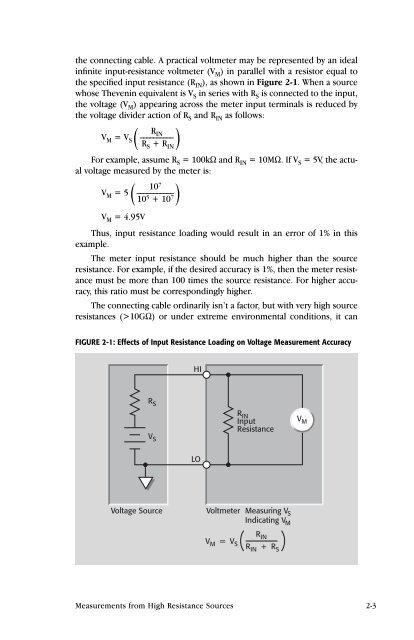
- Page 43: 2.1 IntroductionAs described in Sec
- Page 47 and 48: Cable leakage resistance is a commo
- Page 49 and 50: FIGURE 2-6: Guarding Leakage Resist
- Page 51 and 52: Example: Assume R S = 10GΩ and C S
- Page 53 and 54: MaterialTABLE 2-2: Properties of Va
- Page 55 and 56: QuartzQuartz has properties similar
- Page 57 and 58: FIGURE 2-11: Guarding as Applied to
- Page 59 and 60: FIGURE 2-13: Guarding the Leakage R
- Page 61 and 62: FIGURE 2-15: Simplified Model of a
- Page 63 and 64: time and/or temperature. Zero offse
- Page 65 and 66: open-circuited, allow the reading t
- Page 67 and 68: to equalize charges and minimize ch
- Page 69 and 70: If insulators become contaminated,
- Page 71 and 72: The input resistance of a feedback
- Page 73 and 74: ence. However, in some cases, shiel
- Page 75 and 76: FIGURE 2-27: Feedback Coulombmeter
- Page 77 and 78: Advantages of Using a Coulombmeter
- Page 79 and 80: FIGURE 2-30: Constant-Voltage Metho
- Page 81 and 82: In addition to the voltage drop lim
- Page 83 and 84: FIGURE 2-34a: Effects of Cable Resi
- Page 85 and 86: Such devices require extreme care i
- Page 87 and 88: charge will be lost through the zer
- Page 89 and 90: FIGURE 2-40: Proper ConnectionCurre
- Page 91 and 92: Figure 2-43 shows an example of AC
- Page 93 and 94: fering voltage or current. A guard
- Page 95 and 96:
esponse is the rise time of the ins
- Page 97 and 98:
FIGURE 2-47: Shunt Capacitance Effe
- Page 99 and 100:
Resistance Measurements (Constant-C
- Page 101 and 102:
FIGURE 2-52: Noise Voltage vs. Band
- Page 103 and 104:
Source ResistanceAfter the bandwidt
- Page 105 and 106:
a. ConfigurationShieldCenterconduct
- Page 107 and 108:
• Shielding and Guarding: The fix
- Page 109 and 110:
floating circuits, a second grounde
- Page 111 and 112:
3.1 IntroductionLow voltage and low
- Page 113 and 114:
Thermoelectric EMFsThermoelectric v
- Page 115 and 116:
Reversing Sources to Cancel Thermoe
- Page 117 and 118:
quency spectrum of these interferen
- Page 119 and 120:
ment is almost entirely determined
- Page 121 and 122:
FIGURE 3-9: Low Voltages Generated
- Page 123 and 124:
FIGURE 3-11a: Multiple Grounds (Gro
- Page 125 and 126:
Common-Mode Reversal ErrorsReversin
- Page 127 and 128:
FIGURE 3-14: Two-Wire Resistance Me
- Page 129 and 130:
FIGURE 3-16: Canceling Thermoelectr
- Page 131 and 132:
Both V A and V B are affected by th
- Page 133 and 134:
If using a micro-ohmmeter or DMM to
- Page 135 and 136:
FIGURE 3-20: Dry Circuit Testing Us
- Page 137 and 138:
SECTION 4Applications
- Page 139 and 140:
For timing and integrating applicat
- Page 141 and 142:
FIGURE 4-2:Using an Electrometer to
- Page 143 and 144:
If current flows, the electrodes wi
- Page 145 and 146:
4.3 Low Current Measurement Applica
- Page 147 and 148:
DC. The Model 6517A can also be use
- Page 149 and 150:
voltage (V DS ) and measures the re
- Page 151 and 152:
The Keithley Model 248 High Voltage
- Page 153 and 154:
FIGURE 4-16: Ion Collector with Gro
- Page 155 and 156:
Figure 4-19 shows a Model 6430 conn
- Page 157 and 158:
FIGURE 4-21: SIR Test System to Mea
- Page 159 and 160:
FIGURE 4-22: Volume ResistivityElec
- Page 161 and 162:
these problems, the Alternating Pol
- Page 163 and 164:
FIGURE 4-25: Four-Point Collinear P
- Page 165 and 166:
Using two electrometers eliminates
- Page 167 and 168:
A plot of this function is shown in
- Page 169 and 170:
FIGURE 4-31: van der Pauw Measureme
- Page 171 and 172:
Through interactive programming, th
- Page 173 and 174:
objects. As discussed in Section 2.
- Page 175 and 176:
FIGURE 4-36: Faraday CupOutside Ele
- Page 177 and 178:
FIGURE 4-38: Connections for Standa
- Page 179 and 180:
FIGURE 4-40: Microcalorimeter with
- Page 181 and 182:
Measurement MethodFigure 4-42 illus
- Page 183 and 184:
FIGURE 4-43: Using a Nanovoltmeter
- Page 185 and 186:
exceed the critical current of the
- Page 187 and 188:
equation for V/I. Most materials ha
- Page 189 and 190:
FIGURE 4-49: van der Pauw Connectio
- Page 191 and 192:
5.1 IntroductionChoosing a specific
- Page 193 and 194:
TABLE 5-1a: Low Current/High Resist
- Page 195 and 196:
Table 5-1b: Source-Measure Instrume
- Page 197 and 198:
Table 5-2: High Speed Power Supplie
- Page 199 and 200:
Table 5-3: Connectors, Adapters, an
- Page 201 and 202:
Table 5-4: CablesTERMINATIONS LENGT
- Page 203 and 204:
Table 5-5: Test Leads and ProbesMOD
- Page 205 and 206:
Table 5-6: Switching Cards for the
- Page 207 and 208:
Table 5-6: Switching Cards for the
- Page 209 and 210:
Table 5-8: Switching Cards for the
- Page 211 and 212:
APPENDIX ALow LevelMeasurementTroub
- Page 213 and 214:
Measurement Type andTypical Applica
- Page 215 and 216:
Proper cable and connector assembly
- Page 217 and 218:
APPENDIX CGlossary
- Page 219 and 220:
channels. For matrix cards, a chann
- Page 221 and 222:
R. Buckminster Fuller. Sometimes ca
- Page 223 and 224:
NORMAL-MODE REJECTION RATIO (NMRR).
- Page 225 and 226:
SOURCEMETER. A SourceMeter instrume
- Page 227 and 228:
APPENDIX DSafetyConsiderations
- Page 229 and 230:
The types of product users are:Resp
- Page 231 and 232:
are the same. Other components that
- Page 233 and 234:
1/f noise, 3-7 to 3-83dB point, 2-5
- Page 235 and 236:
Normal mode rejection ratio (NMRR),
- Page 237 and 238:
Specifications are subject to chang
- Page 239:
Specifications are subject to chang