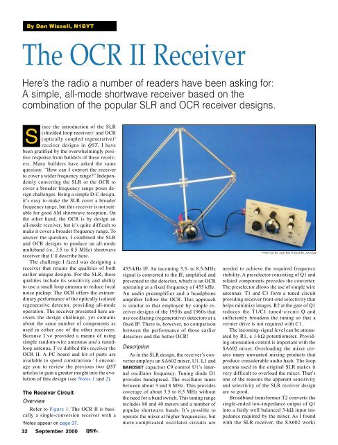
By Dan Wissell, N1BYTThe OCR II ReceiverHere’s the radio a number of readers have been asking for:A simple, all-mode shortwave receiver based on thecombination of the popular SLR and OCR receiver designs.ince the introduction of the SLRS(shielded loop receiver) 1 and OCR(optically coupled regenerative) 2receiver designs in <strong>QST</strong>, I havebeen gratified by the overwhelmingly positiveresponse from builders of these receivers.Many builders have asked the samequestion: “How can I convert the receiverto cover a wider frequency range?” Independentlyconverting the SLR or the OCR tocover a broader frequency range poses designchallenges. Being a simple D-C design,it’s easy to make the SLR cover a broaderfrequency range, but this receiver is not suitablefor good AM shortwave reception. Onthe other hand, the OCR is by design anall-mode receiver, but it’s quite difficult tomake it cover a broader frequency range. Toanswer the question, I combined the SLRand OCR designs to produce an all-modemultiband (ie, 3.5 to 8.5 MHz) shortwavereceiver that I’ll describe here.The challenge I faced was designing areceiver that retains the qualities of bothearlier unique designs. For the SLR, thesequalities include its sensitivity and abilityto use a small loop antenna to reduce localnoise pickup. The OCR offers the extraordinaryperformance of the optically isolatedregenerative detector, providing all-modeoperation. The receiver presented here answersthe design challenge, yet containsabout the same number of components asused in either one of the other receivers.Because I’ve provided a means of usingsimple random-wire antennas and a tunedloopantenna, I’ve dubbed this receiver theOCR II. A PC board and kit of parts areavailable to speed construction. 3 I encourageyou to review the previous two <strong>QST</strong>articles to gain a greater insight into the evolutionof this design (see Notes 1 and 2).The Receiver CircuitOverviewRefer to Figure 1. The OCR II is basicallya single-conversion receiver with a1Notes appear on page 37.32 <strong>September</strong> <strong>2000</strong>455-kHz IF. An incoming 3.5- to 8.5-MHzsignal is converted to the IF, amplified andpresented to the detector, which is an OCRoperating at a fixed frequency of 455 kHz.An audio preamplifier and a headphoneamplifier follow the OCR. This approachis similar to that employed by simple receiverdesigns of the 1950s and 1960s thatuse oscillating (regenerative) detectors at afixed IF. There is, however, no comparisonbetween the performance of those earlierdetectors and the better OCR!DescriptionAs in the SLR design, the receiver’s converteremploys an SA602 mixer, U1. L1 andBANDSET capacitor C9 control U1’s internaloscillator frequency. Tuning diode D1provides bandspread. The oscillator tunesbetween about 3 and 8 MHz. This providescoverage of about 3.5 to 8.5 MHz withoutthe need for a band switch. This tuning rangeincludes 80 and 40 meters and a number ofpopular shortwave bands. It’s possible tooperate the mixer at higher frequencies, butmore-complicated oscillator circuits arePHOTOS BY JOE BOTTIGLIERI, AA1GWneeded to achieve the required frequencystability. A preselector consisting of Q1 andrelated components precedes the converter.The preselector allows the use of simple wireantennas. T1 and C1 form a tuned circuitproviding receiver front-end selectivity thathelps minimize images. R2 at the gate of Q1reduces the T1/C1 tuned-circuit Q andsufficiently broadens the tuning so that avernier drive is not required with C1.The incoming-signal level can be attenuatedby R1, a 1-kΩ potentiometer. Providingattenuation control is important with theSA602 mixer. Overloading the mixer createsmany unwanted mixing products thatproduce considerable audio hash. The loopantenna used in the original SLR makes itvery difficult to overload the mixer. That’sone of the reasons the apparent sensitivityand selectivity of the SLR receiver designare so good.Broadband transformer T2 converts thesingle-ended low-impedance output of Q1into a fairly well balanced 3-kΩ input impedancerequired by the mixer. As I foundwith the SLR receiver, the SA602 works
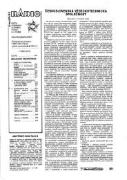
A front-panel view of the OCR II.To a builder’s eye, the inside of theOCR II is as attractive as the outside.considerably better when used with balancedinputs and outputs. I found this to betrue even though I expended considerableeffort trying to provide proper single-endedterminations. Note that the preselector isessentially an impedance-matching bufferand provides no gain, thus it has littlechance of oscillating.As with the original SLR, the preselectorcircuit can be removed from the signal pathand a tuned loop antenna used in its place.When a loop antenna is used, connectionsto the mixer are made via C4 and C5. Ingeneral, I find that there is little differencein receiver performance with the loop antennaor the combination of the preselectorand a modest wire antenna. However, byproperly positioning the loop antenna, youcan null local noise sources and strongbroadcast stations⎯the wire antenna alonecannot accomplish this feat.U1’s output is terminated in the primaryof T3, a 455-kHz IF transformer. (I usethese IF transformers wherever possiblebecause they’re inexpensive and allow agood range of impedance-matching flexibility.)T3’s secondary is terminated byR7. This presents an approximate 3-kΩ terminationimpedance to U1. Q2 and T4 forma tuned 455-kHz amplifier. Q3 is used asan impedance-matching stage between T4and T5. This is necessary because the secondaryof T5 is terminated in a relativelylow (and variable) impedance of regenerationcontrols R13 and R14. If not for thebuffering action of Q3, this would impactthe IF amplifier and could result in unwantedoscillations.The 455-kHz energy is coupled to linearoptocoupler U2 via the secondary of T5.An Agilent (formerly Hewlett-Packard)HCPL4562 linear optocoupler is the heartof the OCR. Although its operation is fullydescribed in the original OCR article, abrief explanation of how it works is worthmentioning here. The 455-kHz RF energyis coupled to the cathode of U2’s LED viaT5. This energy modulates the current flowingthrough the LED. Photons from theLED provide the base current for theoptocoupler transistor. The transistor in U2is configured as a 455-kHz Colpitts oscillatorusing L2 and associated components.The current flowing through the LED controlsthe circuit oscillation creating an idealregenerative oscillator. The magic in thisdesign is that by virtue of the LED, boththe RF energy and the regeneration controlare totally isolated from the sensitive areasof the oscillator, such as the tank circuit.This technique delivers a very wellbehaved regenerative detector with none ofthe infamous regenerative detector problems.An infinite impedance detector (Q4)recovers the audio, as opposed to a transformerand RF-choke scheme often employedwith regenerative circuits.The detected audio is band-pass filteredby C22, C25, C28 and R20 and R22. Thesecomponents along with Q5 form the audiopreamplifier. A ubiquitous LM386 (U4) isused as the headphone or loudspeakeramplifier.Regulated voltage is supplied by U3, anLM78L05 three-terminal regulator. Theregulated voltage is used at U1, U2 and tuningdiode D1.Construction DetailsOne of the more difficult tasks in designinga project such as the OCR II is componentselection. When building a single unit,one-off parts, such as those found at fleamarkets or in junk boxes, are okay to use.But when developing a design to be copied,every effort must be made to use readilyavailable parts. This, in turn, often forcesdesign decisions that may appear arbitrary.An example of this process is the trade-offrequired when deciding how to implementthe tuning in the OCR II. Some of the variousoptions included a band switch,pluggable coils or an external VFO. Eachchoice has its own set of complications includingpart availability and cost. For thisproject, I decided to use common 365-pFair-dielectric variable capacitors to eliminatemore complex band-switching circuitsthat require good-quality switches. Becausesuch switches cost about the same as thecapacitor, I used the latter. A vernier dial isused with the BANDSET capacitor. Besidesmaking the tuning easier, it provides a calibrationscale.For the TUNING control, however, I decidedin favor of a low-cost tuning diodeand 10-turn potentiometer. Both of thesedecisions are based upon the availability ofreasonably priced components from at leastone reliable source. 4 In general, I have takena minimum-component design approach,consistent with the desired receiver performance.No components can be eliminatedand still retain good circuit performance.The bulk of the parts are available fromstandard suppliers. The HCPL-4562 (U1)is stocked by Newark Electronics.The frequency-dependent portion of theU1 oscillator design can be scaled for otherfrequencies of interest in the lower HF region.However, for operation above about10 MHz, consider using an external, wellshieldedVFO for improved stability.Instead of the PC board, you may useany of the standard construction techniquessuch as point-to-point wiring on a copper-<strong>September</strong> <strong>2000</strong> 33
- Page 6 and 7: September 2000 Volume 84 Number 9C
- Page 11 and 12: THE AMERICAN RADIORELAY LEAGUE INCT
- Page 14: Get to Know Your Section ManagerThe
- Page 18: Cosponsors for S.2183Introduced by
- Page 22 and 23: Calling All Holiday Photos!Calling
- Page 26 and 27: CORRESPONDENCEYour opinions count!
- Page 30 and 31: By David Blaschke, W5UNMBAThe Might
- Page 32 and 33: By Bill Wageman, K5MATGrid Chasing:
- Page 36 and 37: 34 September 2000 Figure 1
- Page 38 and 39: its signal in a general-coverage re
- Page 40 and 41: By Dick Goodman, WA3USGThe Monster
- Page 42 and 43: Figure 4—Schematic diagram of the
- Page 44 and 45: elative power levels of the control
- Page 46 and 47: The elegant Butterfly with its ATVp
- Page 48 and 49: Ross Hull, 3JU, at his station inMe
- Page 50 and 51: By Jean Wolfgang, WB3IOSJamboree On
- Page 52 and 53: By Lew Malchick, N2RQSchool Club Ro
- Page 54 and 55: By Dave Patton, NT1NARRL Board Thin
- Page 56 and 57: Summary of Major Board ActionsMinut
- Page 58 and 59: Manager, delivered his report on th
- Page 60 and 61: ucts, and promote more efficient us
- Page 62 and 63: Figure 3—To change your display c
- Page 64 and 65: ity suffers. That is, it’s more d
- Page 66 and 67: in building a higher-performance re
- Page 68 and 69: SHORT TAKESEZNEC 3.0 for WindowsBy
- Page 70 and 71: HINTS & KINKSDOX CONTROL FOR A YAES
- Page 72 and 73: HAPPENINGSARRL Says Amateur Service
- Page 74 and 75: Seminole County to erect a 35-foot
- Page 76 and 77: Reviewed by Rich Arland, K7SZQST Co
- Page 78 and 79: through an antenna tuner, and was r
- Page 80 and 81: to use lighter plug equipped vehicl
- Page 82 and 83: PUBLIC SERVICEThe Trials and Reward
- Page 84 and 85:
HOW’S DX?Tristan da Cunha and Gou
- Page 86 and 87:
THE WORLD ABOVE 50 MHZInto the 21st
- Page 88 and 89:
were more than half a dozen 2-meter
- Page 90 and 91:
health, safety and aesthetics conce
- Page 92 and 93:
AMATEUR SATELLITESA “Hot” After
- Page 94 and 95:
Christopher R.Gonyea, KB1AZKGoshen,
- Page 96 and 97:
QRP POWERVintage QRPFiring up an ol
- Page 98 and 99:
HAMFEST CALENDAR† ARRL HamfestAtt
- Page 100 and 101:
Mobile to the Max