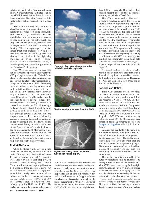
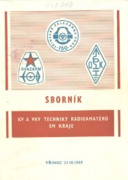
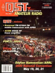
elative power levels of the control signaland ATV transmitter are calibrated to allowthe ATV link to fail before the radio controllink goes down. The rule of thumb is, if thepicture starts getting fuzzy, it’s time to headback!With a smaller and fully symmetricshoulder wing, the Ugly Stick is fullyaerobatic. The video from doing loops, rollsand spins is truly spectacular! It’s likeactually being in the plane, except you getto keep your lunch. The extra weight anddrag from the ATV package, however, leadsto longer takeoff rolls and screaming-hotlandings. The camera package represents alarger fractional increase in weight forthis airplane and maintaining sufficientairspeed is critical with the high wingloading. But even though it glidessomewhat like a streamlined brick, ithandles pretty well once you get used tothe “heaviness” of the stick.The TH-60 has enough wing area (875square inches) and power to easily carry theATV package without strain. This airframealso provides superior wind penetration andcrosswind landing characteristics ascompared to the motor glider. Increasingthe wing incidence one degree over stockand outfitting the airplane with fullyfunctional flaps dramatically improvedflight characteristics at minimumcontrollable airspeed and helped to slow thelandings to more normal speeds. I’verecently installed a second-generation ATVtransmitter inside the TH-60 fuselage.Although the weight is still about the same,getting rid of the extra drag of the exteriorATV package yielded significant handlingimprovements. The forward-lookingcamera is mounted in a small box attachedto the windshield and the down-lookingcamera looks through a hole in the bottomof the fuselage. As before, the look anglecan be selected in flight. Microscope slidesserve as windscreens to keep bugs and fuelspray off the camera optics. A future projectwill explore the use of a two-axis gyro tohelp stabilize flight in gusty winds.Rocket PlatformsWhile the students at K-SAT build theirthree-foot-tall rockets, the adult kids buildtheirs. The big kids’ “heavy lifters” stand11 feet tall and carry an ATV transmitterwith video overlays that display GPSposition, speed, heading and altitude.Constructed under the expert guidance ofBill Wagner, these rockets require FAAcoordination and need lots of empty landaround them to fly. After months of raindelays, we finally got a chance to fly one ofthe big rockets in May 1999 at a 22,000-acre cattle ranch in southern Texasbelonging to Rik Hoffman, K5SBU. Therocket carried a side-looking color camera42 <strong>September</strong> <strong>2000</strong>Figure 2—Big Yeller takes to the skieswith GPS and ATV payloads.The Hondo airport as seen from the TH-60.Figure 3—Looking down the rocketfuselage at Hondo airport.and a 1.5-W ATV transmitter. After the prefiledclearance was obtained from Houstoncenter via cell phone, we started a quickcountdown and hit the switch. The rocketleaped into the air atop a mountain of fireand roared away with Doppler-shiftedthunder, ever decreasing in pitch as therocket accelerated to 401 MPH. During itsseven-second burn, the rocket consumed$360 of solid fuel at a rate of slightly morethan $50 per second. The rocket thencoasted straight up for another 23 seconds,reaching an altitude of 7000 feet.The ATV system worked flawlessly,providing spectacular video for the entireflight. The view was particularly impressiveas the rocket approached, penetrated andascended above a thin cloud deck at 3500feet. As the rocket passed apogee and beganto descend, the computerized altimeterssensed the increase in barometric pressureand deployed the parachutes. Five minuteslater the rocket landed in a mesquite treejust over a mile from the launch pad. Aftertouchdown, the ATV signal was still comingthrough, showing an excellent view of thethick underbrush and reporting its landingcoordinates on the GPS data overlay. Wepunched the coordinates into a hand-heldGPS unit and went right to the landing site.A photograph of the launch is shown inFigure 2.A second rocket with its own ATVpayoad was constructed, this time with adown-looking black-and-white camera.Both rockets were launched on December4, 1999. You can see a view from one ofthe rockets in Figure 3.Cameras and OpticsSmall CCD cameras are still evolving.Our first ATV transmitter used a single boardblack-and-white camera with a pinhole lensand required 9-V dc at 100 mA. Our firstcolor camera ran on 10.5 V, had three PCboards and required 300 mA. Our presentcamera is a much smaller single-board colormodel that requires 10 V at 100 mA. A seriesstring of 1N4001 rectifier diodes is used todrop the 12-V ATV transmitter batteryvoltage to about 10 V dc. The cameras wereobtained from Supercircuits (see theEquipment Suppliers sidebar) in Austin,Texas.Cameras are available with pinhole ormultielement lenses. Both give a 70 to 90°field of view, with the wider view preferredfor airborne operations. The multielementlenses have less barrel distortion than thepinhole versions, but are physically larger.The apparent curvature of the earth evidentin some of the aerial views isn’t real—it’scaused by the barrel distortion of thecamera lens.The picture quality obtainable fromoutdoor operations can be improved byadding filters in front of the camera lens.Most CCD cameras are set up for low-lightperformance and suffer from overexposurein bright sunshine. The symptoms caninclude blank-out or streaking if the suncomes into the field of view, sluggish AGCresponse and excessive contrast, causingloss of ground detail below a bright sky.This can be fixed by adding a neutraldensityfilter to the front of the lens. Values
etween ND 0.5 and ND 1.5 work well. Thewing-mounted ATV package was modifiedto include a 37-mm screw-in adapter toaccept one or more photographic filters.Infrared and ultraviolet (haze) filters canimprove color balance.Another parameter affected by lightlevel is shutter speed, the primary exposurecontrol of a CCD camera. Without neutraldensityfilters, the shutter speeds can befaster than a ten-thousandth of a second.This is fast enough to stop the prop of a12,000-RPM engine if the camera is lookingthrough the prop arc. The resulting stroboscopiceffect is fascinating to some anddownright annoying to others. Adding theneutral-density filter starves the camera forlight and it responds by slowing its shutterspeed. This causes the prop to blur or evendisappear if the prop is dark in color, givinga more pleasing frontal view. Thepresent external ATV package uses one ortwo neutral-density filters screwed onto thechassis ahead of the camera lens.Frequency SelectionSeveral factors influence the choice ofoperating frequency for the ATV transmitter.These include range, efficiency and receivercomplexity. ATV frequency bandsinclude 70 cm, 33 cm and 24 cm, and2.4 GHz and above. It takes four times asmuch power to get the same signal at900 MHz as it does at 450 MHz. Transmittersare also more efficient at 450 MHz,meaning smaller and less massive batteriescan be used on the already overburdenedRC aircraft. Also, it just happens that cableTV channels 58 through 60 fall completelywithin the 70-cm band (427.25, 433.25 and439.25 MHz, respectively). This means thata cable-ready TV or VCR can be used as areceiver without any additional electronics.Transmitter suppliers are well aware of thisfact and offer transmitter boards alreadytuned to these frequencies. These factorsmake 70 cm our hands-down favorite forairborne ATV activities.Interference to and from other amateurservices (FM repeaters and satellite operations)isn’t really an issue because the airbornepackages typically use only 80 to 200mW and are flown for short durations from(necessarily) remote locations. Maximumrange, even with a beam for a receivingantenna, is only a few miles.AntennasOur antennas are designed to maximizerange and minimize interference betweenco-located functions. In the airplanes, thisis the ATV transmitter and the flight packreceiver. In the rocket, it is the ATV transmitterand the GPS receiver. An additionalgoal is to provide uniform coverage withminimal dropouts in the coverage pattern.The view from the K-SAT rocket at 7000feet.Figure 4—The circularly-polarized ATVantenna on the rocket payload bulkhead.The best airplane ATV antennas have beensimple vertical ground-planes or verticaldipoles. For short-range flights the receiveantenna was a simple quarter-wavelengthvertical mounted on my car with a magmount.For longer-range airplane flightsand for rocket flights, a 10-element beam(a KLM 440-10x) was connected to the receiver.The airplane’s flight pack receiveruses a standard trailing-wire antennasupplied by the manufacturer. The controlreceiver and antenna are configured forhorizontal polarization and are mounted asfar away from the ATV antenna as possible.The rocket payload contains two antennas:one for the ATV transmitter and onefor the GPS receiver. The 70-cm ATV antennais a circularly polarized turnstilemounted on the wooden bulkhead separatingthe payload section from the booster.A photograph of the antenna is shown inFigure 4. When worked against a horizontallypolarized beam on the ground, goodsignals—without dropouts—were obtainedfrom the spinning rocket (as it ascendedoverhead and as it drifted upside downto the landing site a mile from the launchsite).The GPS antenna was glued to the outsideof the rocket. A folded dipole designwas selected for simplicity, conformalmounting and frequency selectivity. Thefolded dipole was placed on the rocketas far away from the ATV antenna as possible.Tuned for 1570 MHz and fed with ahalf-wave coaxial balun, it provided goodrejection of the 427-MHz ATV signal. Theantenna was capacitively coupled to thecoaxial feed line to keep from shorting outthe preamplifier bias voltage placed onthe coax by the GPS receiver. ExcellentGPS coverage was obtained during theflight.If the ATV transmitter is connected tothe antenna with a coaxial feed line, a balunwill prevent the feed line from becoming apart of the antenna. This will eliminate feedline radiation (which can distort the radiationpattern), keep the ATV RF away fromsensitive onboard receivers and facilitatetuning the antenna. Choke, ferrite bead,sleeve and current transformers are goodbalun candidates. I’ve had excellent resultswith a simple choke balun formed by coilingthe RG-174 feed line at the antenna feedpoint. This eliminates unwanted feed lineradiation and decouples the feed line fromthe antenna, significantly improving theSWR.Operational ConsiderationsOne safety issue that must be addressedfor safe RC aircraft operation is eliminatinginterference from the ATV transmitterto the flight-control receiver. Both use a 60-Hz frame rate, and ATV signals can causeserious interference to the flight pack receiverand subsequent loss of aircraft control.Although the control frequency is at72 MHz (or at 6 meters for hams), receiver“desensing” can occur if the ATV signalenters the receiver through the antenna,servo or battery leads. I took several stepsto eliminate this problem. First, the TVcamera and the ATV transmitter weremounted in a shielded enclosure. Copperfoil tape makes an excellent lightweightshield when applied to plastic and balsaenclosures. The antennas for the ATV transmitterand flight pack receiver were placedas far apart as possible and cross-polarized(ATV vertical and flight pack horizontal).A balun was used in the ATV antenna coaxto eliminate unwanted feed-line radiation.To eliminate conducted interference, separatebatteries were used for the flight packand the ATV package, and the direct connectionbetween the flight receiver and theATV package was decoupled by inserting a1-k ohm resistor in series with the signaland the ground wire.With the ATV package mounted atop theTH-60, I couldn’t eliminate all of the interferenceuntil I decoupled the leads from theaileron servos by winding them around aferrite toroid. Ferrite beads and toroids canbe effective only if they are suitable for useat 450 MHz. Most are not, and themanufacturer’s data sheets should be consultedwhen selecting the correct ferritecores for various frequencies.<strong>September</strong> <strong>2000</strong> 43
- Page 6 and 7: September 2000 Volume 84 Number 9C
- Page 11 and 12: THE AMERICAN RADIORELAY LEAGUE INCT
- Page 14: Get to Know Your Section ManagerThe
- Page 18: Cosponsors for S.2183Introduced by
- Page 22 and 23: Calling All Holiday Photos!Calling
- Page 26 and 27: CORRESPONDENCEYour opinions count!
- Page 30 and 31: By David Blaschke, W5UNMBAThe Might
- Page 32 and 33: By Bill Wageman, K5MATGrid Chasing:
- Page 34 and 35: By Dan Wissell, N1BYTThe OCR II Rec
- Page 36 and 37: 34 September 2000 Figure 1
- Page 38 and 39: its signal in a general-coverage re
- Page 40 and 41: By Dick Goodman, WA3USGThe Monster
- Page 42 and 43: Figure 4—Schematic diagram of the
- Page 46 and 47: The elegant Butterfly with its ATVp
- Page 48 and 49: Ross Hull, 3JU, at his station inMe
- Page 50 and 51: By Jean Wolfgang, WB3IOSJamboree On
- Page 52 and 53: By Lew Malchick, N2RQSchool Club Ro
- Page 54 and 55: By Dave Patton, NT1NARRL Board Thin
- Page 56 and 57: Summary of Major Board ActionsMinut
- Page 58 and 59: Manager, delivered his report on th
- Page 60 and 61: ucts, and promote more efficient us
- Page 62 and 63: Figure 3—To change your display c
- Page 64 and 65: ity suffers. That is, it’s more d
- Page 66 and 67: in building a higher-performance re
- Page 68 and 69: SHORT TAKESEZNEC 3.0 for WindowsBy
- Page 70 and 71: HINTS & KINKSDOX CONTROL FOR A YAES
- Page 72 and 73: HAPPENINGSARRL Says Amateur Service
- Page 74 and 75: Seminole County to erect a 35-foot
- Page 76 and 77: Reviewed by Rich Arland, K7SZQST Co
- Page 78 and 79: through an antenna tuner, and was r
- Page 80 and 81: to use lighter plug equipped vehicl
- Page 82 and 83: PUBLIC SERVICEThe Trials and Reward
- Page 84 and 85: HOW’S DX?Tristan da Cunha and Gou
- Page 86 and 87: THE WORLD ABOVE 50 MHZInto the 21st
- Page 88 and 89: were more than half a dozen 2-meter
- Page 90 and 91: health, safety and aesthetics conce
- Page 92 and 93: AMATEUR SATELLITESA “Hot” After
- Page 94 and 95:
Christopher R.Gonyea, KB1AZKGoshen,
- Page 96 and 97:
QRP POWERVintage QRPFiring up an ol
- Page 98 and 99:
HAMFEST CALENDAR† ARRL HamfestAtt
- Page 100 and 101:
Mobile to the Max