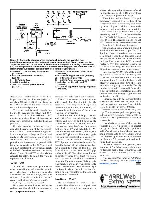
Figure 4—Schematic diagram of the control unit. All parts are available fromRadioShack unless otherwise indicated. Layout is not critical. Simply mount the five“capacitor switches” on the front of the enclosure along with the tuning potentiometer(R3). By using various combinations of switches and tuning, you can tweak the loop formaximum received signal strength from the comfort of your shack.C1—2200µF, 35-V electrolytic capacitor(272-1020)C2—0.1µF ceramic disk capacitor(272-135)F1—0.5A, 120 V fuseR1—240 Ω resistorR2—4.7 kΩ trimmer potentiometer(271-281)elegant way to match and interconnect theloop to the coax, and it works perfectly. Iran about 60 feet of RG-58 coax from theSO-239 connector on the capacitor box tothe shack-mounted preamp.The control unit is equally simple (seeFigure 4). Because the relays had 24-Vcoils, I used a RadioShack 24-Vtransformer and a full-wave bridge for therelay power supply. This pulled in the relaysjust fine.For the varactor tuning voltage, Iregulated the raw output of the relay supplywith an LM-317 three-pin voltage regulator.I set the regulated voltage to 20 V dc andused a 50-kΩ potentiometer to provide 0 to20 V to the diodes. One side of thepotentiometer is connected to ground whilethe other connects to the 20-V regulatedoutput. A wire from the wiper arm connectsto the 200-kΩ resistor that feeds the tuningdiodes. A set of five SPST toggle switchesactivate the relays to select the variouscapacitor combinations.To the Roof!A lot of Old-Timers say loops don’t haveto be mounted high, but I wanted to get thisparticular loop as high as possible.Remember that this is a large, unwieldyantenna. I first tried to hoist it to the roofmyself, with almost disastrous results.Get help erecting this antenna!If the loop tilts more than 30°, one personprobably can’t handle it. It’s also somewhat40 <strong>September</strong> <strong>2000</strong>R3—50 kΩ potentiometer, linear taper(271-1716)S1-S5—SPST toggle switches (275-624)S6—SPST switch (275-603)T1—120/25.2-Vac transformer (273-1366)U1—Bridge rectifier, 4A, 100 PIV(276-1171)U2—LM317T adjustable voltage regulator(276-1778)heavy and has noticeable wind resistance.I hoped to be able to rotate the antennawith a small RadioShack rotator, but thesheer size of the loop made it impossibleto mount the rotator near the antenna, so Imounted it at the bottom of the antennamast support assembly.I took the completed loop assembly,with a five-foot mast sticking out of thebottom, and carefully laid it down on theground and attached a 10-foot section ofmast to the existing five-footer. I slid a ninefootsection of 1 1 /4-inch schedule 40 PVCover the 10-foot mast section, making surethat the PVC pipe was fully contacting thepipe from the completed loop assembly.Next, I drilled a small hole through thePVC pipe and internal mast about two feetfrom the bottom of the entire assembly. Iran a small bolt through this hole andfastened it with a nut. Now the PVC pipecouldn’t slip off. The whole assembly canbe carefully raised by at least two peopleand bracketed to the side of a structureusing four TV mast brackets. Make sure themast brackets are securely anchored to theside of the structure. Once the assembly isbracketed in place, the bolt you installedshould be removed, allowing the loop to berotated from the bottom.How Does it Work?I had my doubts about loops before I builtthis one. The others were poor performersand I had to tweak them incessantly toachieve only marginal performance. After allthe adjustments, my short 160-meter sloperwould always outperform the loops.When I finished the Monster Loop, Itemporarily strapped it to the deck of ourpool (which drew an interesting stare frommy wife). I promised her it was onlytemporary and proceeded to connect thecontrol wires and coax. Back in the shack, Ipowered up the RX-320, which was tuned tothe AMRAD LF beacon frequency on136.745 kHz. The receiver came to life andDCU (a commercial data station somewherein Nova Scotia) blared from the speaker!The Canadian signal was quite strong. Iswitched to the 160-meter sloper. Yes! Thesignal was there, but nowhere near as strongas the loop. I flipped the switch on the controlbox that inserted a 1640-pF capacitor acrossthe loop. The signal from DCU increasedmarkedly. With that particular capacitor inparallel with the loop, the Varactor diodesallowed me to tune the loop to resonance.Later that day, WA2XTF/6 and /12 movedmy S-meter for the first time! And every timeI compared the loop to the sloper, the loopwon hands down. By rotating the loop I couldeffectively eliminate about 80% of the linenoise that was giving me trouble. The bigloop has an incredibly deep null. Being ableto null unwanted noise sometimes makes thedifference between hearing a signal well andnot hearing it at all.I experimented with the loop’s switchablecapacitors and found that the loop can bemade to resonate anywhere from slightlybelow 90 kHz to just above 450 kHz.Remote tuning diodes are the only wayto go. The resonance peaks are quite sharp,and you have to retune every couple of kHz,but the incredible performance makes it allworthwhile.If you build a version of this loop foryourself, please remember to be carefulduring installation. Although it performswell, it’s awkward to install. I also have myfinger crossed as to its survivability. We’vehad a few strong winds since I’ve installedthe “Monster.” It swayed back and forth,but no harm was done.Last but not least—building this big loopwas a lot of fun. It had been a while sinceI’d brought back a load of hardware andturned it into something useful andattractive.You can contact the author at 199 MapleAve, Mechanicsburg, PA 17055; wa3usg@compuserve.com.
By Steve Cerwin, WA5FRFAmateur Television fromModel Planes and RocketsInstall an ATV camera and transmitter in a model airplane or rocketand you’ll see the world from a very different perspective!ince I began flying radio controlledairplanes in 1980, I hadSwanted to include cameras andtelevision equipment as payloads.Although I enjoyed early success with 35-mm photography, the television gear of thatera was too bulky and expensive for myplane and pocketbook. Within the last fiveor so years, however, miniature TV camerashave become astonishingly small,lightweight, affordable and require onlyminimal power. And RF transmitter boardsshare similar characteristics. Theavailability of suitable components and theadded attraction of contributing to anadvanced middle school program broughtmy dream to reality nearly 20 years later.The Krueger School of Applied Technology(K-SAT) at Krueger MiddleSchool in San Antonio, Texas, has a trulyenlightened magnet program for sixth,seventh and eighth graders. Headed byCalvin Best, the program adds a heavyscience and aerospace spin to all academicsubjects. In addition to their normal classes,the students design and build model rocketsand planes and are involved with thesupervised flying of high-altitude rocketsand radio-controlled model airplanes. Thestudents also prepare for and obtain theirham licenses as part of the curriculum.My friend, Charles Thomas, WA3PAY, andI build and fly ATV-equipped RC airplanesfor our own enjoyment, but deriveas much or more satisfaction from sharingour experiences with the students. Charlesand I serve as mentors for the K-SATprogram.Another K-SAT mentor, Bob Morris, isa retiree from the United States GeologicalSurvey (USGS). Thanks to his efforts, wewere invited to fly an airborne ATV systemequipped with a GPS position overlay tosurvey the Texas flood plain areas affectedby the October 1998 floods. This was doneFigure 1—The author with an ATV-equippedUgly Stick.on a demonstration/volunteer basis in muchthe same way hams provide the NationalWeather Service with rainfall data. Usingthe camera-equipped planes we were ableto fly over and videotape otherwise inaccessiblecreeks and riverbeds. The USGSused this data to assess water flow resistanceand flood potential in times of highrain. The radio-controlled “camera planes”offered a low-cost and low-risk alternativeto manned flight. The experiment turned outto be a highly successful and satisfyingadventure.Described below are some of theprojects we have undertaken and sharedwith the school.Airplane PlatformsThe first (and the most versatile to date)airborne ATV transmitter was built as acompletely self-contained unit that couldbe attached over the wing of any suitablemodel airplane with rubber bands. Theoriginal package contained a singleforward-looking CCD camera, an 80-mWtransmitter, a 12-V NiCd battery pack andan integral monopole antenna. The packagemeasured 4 × 6 × 1.25 inches and weighedabout 1.25 pounds. The inside of the plasticAn ATV frame capture from the Butterfly.chassis was lined with copper foil tape toprovide a lightweight shield for theelectronics and a ground plane for theantenna. Subsequent revisions haveincluded connections for a second, downlookingcamera, a switch to select the lookangle by remote control, and optical filtersto improve the video quality. A photographof the transmitter mounted atop a .40-sizedUgly Stick is shown in Figure 1.The Butterfly motor glider has proven tobe the most stable platform flown to date.The Butterfly sports a 99-inch wingspan andnearly 1000 square inches of wing area. Ithas been fitted with a .32-size engine todevelop enough power to get the 1.25-poundcamera package airborne with a shorttakeoff roll on a grass runway. The large sizeand inherent stability of this airframe makesit very easy for an experienced pilot to flyvisually (looking at the airplane) or as aremotely piloted vehicle (RPV, looking atthe video). As an RPV, the plane flies verymuch like a computerized flight simulator.In fact, when flying in this mode it’spossible to inadvertently fly the plane outof range unless a safety pilot is present totell the operator when to turn back towardthe control transmitter. The frequencies and<strong>September</strong> <strong>2000</strong> 41
- Page 6 and 7: September 2000 Volume 84 Number 9C
- Page 11 and 12: THE AMERICAN RADIORELAY LEAGUE INCT
- Page 14: Get to Know Your Section ManagerThe
- Page 18: Cosponsors for S.2183Introduced by
- Page 22 and 23: Calling All Holiday Photos!Calling
- Page 26 and 27: CORRESPONDENCEYour opinions count!
- Page 30 and 31: By David Blaschke, W5UNMBAThe Might
- Page 32 and 33: By Bill Wageman, K5MATGrid Chasing:
- Page 34 and 35: By Dan Wissell, N1BYTThe OCR II Rec
- Page 36 and 37: 34 September 2000 Figure 1
- Page 38 and 39: its signal in a general-coverage re
- Page 40 and 41: By Dick Goodman, WA3USGThe Monster
- Page 44 and 45: elative power levels of the control
- Page 46 and 47: The elegant Butterfly with its ATVp
- Page 48 and 49: Ross Hull, 3JU, at his station inMe
- Page 50 and 51: By Jean Wolfgang, WB3IOSJamboree On
- Page 52 and 53: By Lew Malchick, N2RQSchool Club Ro
- Page 54 and 55: By Dave Patton, NT1NARRL Board Thin
- Page 56 and 57: Summary of Major Board ActionsMinut
- Page 58 and 59: Manager, delivered his report on th
- Page 60 and 61: ucts, and promote more efficient us
- Page 62 and 63: Figure 3—To change your display c
- Page 64 and 65: ity suffers. That is, it’s more d
- Page 66 and 67: in building a higher-performance re
- Page 68 and 69: SHORT TAKESEZNEC 3.0 for WindowsBy
- Page 70 and 71: HINTS & KINKSDOX CONTROL FOR A YAES
- Page 72 and 73: HAPPENINGSARRL Says Amateur Service
- Page 74 and 75: Seminole County to erect a 35-foot
- Page 76 and 77: Reviewed by Rich Arland, K7SZQST Co
- Page 78 and 79: through an antenna tuner, and was r
- Page 80 and 81: to use lighter plug equipped vehicl
- Page 82 and 83: PUBLIC SERVICEThe Trials and Reward
- Page 84 and 85: HOW’S DX?Tristan da Cunha and Gou
- Page 86 and 87: THE WORLD ABOVE 50 MHZInto the 21st
- Page 88 and 89: were more than half a dozen 2-meter
- Page 90 and 91: health, safety and aesthetics conce
- Page 92 and 93:
AMATEUR SATELLITESA “Hot” After
- Page 94 and 95:
Christopher R.Gonyea, KB1AZKGoshen,
- Page 96 and 97:
QRP POWERVintage QRPFiring up an ol
- Page 98 and 99:
HAMFEST CALENDAR† ARRL HamfestAtt
- Page 100 and 101:
Mobile to the Max