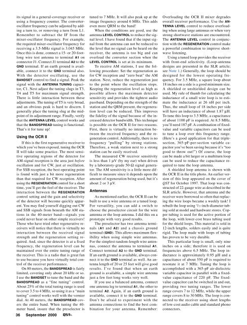
its signal in a general-coverage receiver orusing a frequency counter. The converteroscillatorfrequency can be adjusted by addinga turn to, or removing a turn from L1.Remember to subtract the IF from themixer-oscillator frequency. For example,the required mixer-oscillator frequency forreceiving a 3.5-MHz signal is 3.045 MHz.Once this is done, connect a 15- or 20-footlongwire test antenna to terminal A1 onconnector J1. Connect J1 terminal A2 to theGND terminal. If an earth ground is available,connect it to the GND terminal also.With the detector oscillating, use theBANDSET control to find a signal. Peak thesignal with the ANTENNA TUNING capacitor,C1. Next adjust the tuning slugs in T3,T4 and T5 for maximum signal strength.There is little interaction between theseadjustments. The tuning of T5 is very broad,and an obvious peak is hard to discern. Igenerally place the tuning slug at the midpointof its adjustment range. Finally, verifythat the ANTENNA LEVEL control works andthat the BANDSPREAD tuning is functional.That’s it for tune up!Using the OCR IIIf this is the first regenerative receiver towhich you’ve been exposed, tuning the OCRII will take some practice. The most sensitiveoperating regions of the detector forAM-signal reception is the area just beforeoscillation and for CW, just at oscillation.For SSB reception, the best operating pointis found with just a bit more regenerationthan that required for CW reception. Afterusing the REGENERATION control for a shorttime, you’ll get the feel of the receiver. Theinteraction between the REGENERATIONcontrol setting and the gain and selectivityof the detector will become quickly apparent.You may find yourself digging out CWand SSB signals from beneath the AM stationsin the 40-meter band⎯signals youcould never hear on other simple receivers!Those who have tried other regenerative receiverswill notice that there is virtually nointeraction between the received signalstrength and the regeneration setting required.And, since the detector is at a fixedfrequency, the regeneration level can bemaintained over the entire tuning range ofthe receiver. This is a radio that is great funto use because you have virtually total controlof the receiver performance.On 80 meters, the BANDSPREAD is fairlylimited, covering only about 20 kHz or so.I use the BANDSET to tune the band and theBANDSPREAD as a “fine tuning” control.About 25% of the total tuning range is usedto cover 3.5 to 4 MHz, so using it as a “maintuning” control works well with the vernierdial. At 40 meters, the BANDSPREAD coversthe entire band. When tuning the 40-meter band, insure that the preselector is36 <strong>September</strong> <strong>2000</strong>tuned to 7 MHz. It will also peak up at theimage frequency around 6 MHz. This addseven more QRM to the band!When the conditions are good, use theantenna LEVEL CONTROL to reduce the signallevel. I have found that if the input signalfrom the antenna can not be reduced tothe level that no signal can be heard on thereceiver, the antenna is too big and canoverload the converter section when theLEVEL CONTROL is set at its minimum.To receive AM stations, I use the followingprocedure: Set the regeneration asfor CW reception and “zero beat” the AMstation. Next, reduce the regeneration justto the point where the oscillation stops.Keeping the regeneration level as high aspossible allows the maximum detectorsensitivity and provides the tightest audiopassband. Depending on the strength of thestation and the QRM present, the regenerationlevel can be reduced. This improvesthe fidelity of the signal because of the increaseddetector bandwidth. This techniqueis possible on the OCR II for two reasons.First, there is virtually no interaction betweenthe received frequency and the regenerationcontrol. Additionally, there is nofrequency “pulling” by strong stations.Therefore, a weak station next to a strongstation can be easily received.The measured CW receiver sensitivityis less than 1 µV (by my ear) when drivenby a laboratory-grade 50-Ω signal generator.The AM sensitivity is a little more difficultto measure since it depends upon theamount of regeneration being used, but it’sabout 2 or 3 µV.AntennasAs mentioned earlier, the OCR II can bebuilt to use a wire antenna or a tuned loop.For versatility, you can add a switch tochoose the preselector circuit for the wireantenna or the loop antenna. I did this on aprototype with very good results.The preselector has two antenna terminals(A1 and A2) and a chassis groundterminal (GND). This allows maximum flexibilitywhen using simple wire antennas.For the simplest random-length wire antennas,connect the antenna to terminal A1.Connect terminal A2 to the GND terminal.If an earth ground is available, always connectit to the GND terminal as well. An antennalength of 20 or 25 feet will give goodresults. I’ve found that when an earthground is available, a simple wire antennajust a few feet long works very well.If you use a balanced antenna, connectone antenna leg to terminal A1, the other toterminal A2. Again, if an earth ground isavailable, connect it to the GND terminal.Don’t be afraid to experiment with theantenna connections to find the best combinationfor your antenna. Remember:Overloading the OCR II mixer degradesoverall receiver performance. Use the AN-TENNA LEVEL control to reduce overloadingwhen using large antennas or when verystrong shortwave stations are encountered.The ANTENNA LEVEL control in conjunctionwith the REGENERATION control makea powerful combination to improve shortwavelistening.Using a tuned loop provides the receiverwith front-end selectivity. (Loop-antennadesigns are presented in the SLR article;see Note 1.) Generally, the loop should bedesigned for the lowest operating frequency.For 3.5 MHz, a square loop about18 inches on a side is a good minimum size.A shielded or unshielded design can beused. My rule of thumb for calculating theinductance of a small wire loop is to estimatethe inductance at 26 nH per inch.Thus, the small loop of 18 inches per sidewill have an inductance of about 1.87 µH.To tune this loop to 3.5 MHz, a capacitanceof about 1100 pF is required. At 8.5 MHz,you’ll need 187 pF. A combination of fixedvalueand variable capacitors can be usedto tune a loop over this frequency range.(Here’s a good application for that triplesection,365-pF-per-section variable capacitoryou’ve been saving because it’s “toogood to throw out!”) Of course, the loopcan be made a bit larger or a multiturn loopcan be used to reduce the capacitance requiredto tune the loop antenna.A shielded loop antenna is shown withthe OCR II in the title photo. An earlier versionof this loop appeared on the cover of<strong>QST</strong> for October 1997. That loop was constructedof 22-gauge wire as described in theSLR article. However, that antenna and thereceiver were borrowed so often that replacingthe wire loops became a weekly task! Irebuilt the loop using 3 /32-inch-diameter tubingsold at model and hardware stores. Coppertubing is used for the active portion ofthe loop, with lower-cost brass tubing usedfor the shield loops. This material is sold in12-inch lengths, solders easily and is quiterigid. The loop made with loops of tubinghas proven to be very durable.This particular loop is small, only nineinches on a side; therefore it is used onfrequencies above 6.5 MHz. The loop inductanceis approximately 0.95 µH and acapacitance of about 550 pF is required toresonate it at 7 MHz. Tuning the loop isaccomplished with a 365-pF air-dielectricvariable capacitor in parallel with a fixedvaluecapacitance of 220 pF. The fixedvaluecapacitor can be switched in and out,providing two tuning ranges. The lowerrange covers 7 to 12 MHz, while the upperrange covers 8 to 30 MHz. The loop is connectedto the receiver using short lengthsof low-cost audio cable and standard phonoconnectors.
SummaryThe OCR II receiver is a simple, allmodemultiband receiver. It retains the bestfeatures of its predecessors, the SLR andOCR receivers. With sensitivity equal tothat of the SLR and the good selectivityprovided by the OCR regenerative detector,the OCR II offers performance greaterthan the sum of its parts. I have enjoyeddesigning this radio, and have had great funoperating it. I thank those builders of theSLR and OCR receivers who have sentme mail and inspired the design. I hopeothers are inspired to try their hand at“homebrewing” this and other projects.Notes1Daniel Wissell, N1BYT, “The 40M SLR—aShielded-Loop Receiver,” <strong>QST</strong>, Oct 1997,pp 33-38.2Daniel Wissell, N1BYT, “The OCR Receiver,”<strong>QST</strong>, Jun 1998, pp 35-38.3Jade Products, Inc,, PO Box 368, EastHampstead, NH 03826-0368; tel 800-523-3776, fax 603-329-4499; jadepro@jadeprod.com; http://www.jadeprod.com/. Jade alsooffers components used in this project.4Additional parts sources include: Dan’s SmallParts and Kits, Box 3634, Missoula, MT 59806-3634; tel and fax: 406-258-2782; http://www.fix.net/dans.html, for variable capacitors andmultiturn potentiometers; The Xtal Set Society,PO Box 3026, St. Louis, MO 63130; tel 800-927-1771; xtalset@midnightscience.com;http://www.midnightscience.com/crystal.html) is one source of 365-pF air-dielectric variablecapacitors.Dan Wissell, N1BYT, was first licensed asWN2WGE and upgraded to Extra in 1984 asN1BYT. He’s been with Compaq ComputerCorporation (formerly Digital EquipmentCorporation) for 20 years. He is currently aPrincipal Member of the technical staff, designingRF and analog systems. You can contactDan at 7 Notre Dame Rd, Acton, MA01720; n1byt@arrl.net.NEW BOOKSNEW BOOKSTHIS WAS RADIOBy Ronald LackmannFirst edition. Copyright <strong>2000</strong> by GreatAmerican Audio Corporation, 33 PortmanRd, New Rochelle, NY 10801; tel 914-576-7660. Hardcover, 14 3 /8 × 11 3 /8 inches, 72pages plus two audio CD-ROMs. $39.95.Available at Barnes & Noble, Borders, andother book retailers.Reviewed by Steve Ford, WB8IMY<strong>QST</strong> Managing Editor◊ This Was Radio is saddled with the difficulttask of distilling the golden age of broadcastradio into a single multimedia (print andaudio) presentation. To a great degree it succeeds,with a few notable shortcomings.The book itself is a handsome large-format“coffee table” tome packed with crispblack and white photography. Tracing the historyof broadcast radio from its roots, for example,we see Frank Nullen in the studio ofKDKA in 1922. Along the bottom of the openingpages is a time line that begins withMarconi in 1895. (Curiously, author RonaldLackmann credits Ambrose Fleming with theinvention of the vacuum tube in 1907, yet failsto mention the contributions of Lee DeForest.)This Was Radio moves forward at a rapidclip with Lackmann’s writing style exuding acontagious enthusiasm for his subject. In additionto the well-composed narrative you’retreated to more fascinating photography. Thecollection ranges from rare studio shots to promotionalimages including photos of BobHope, Fanny Brice (as Baby Snooks), Abbottand Costello, Judy Canova, Jimmy Durante,Orson Wells, New York City mayor FiorelloLaGuardia (reading the Sunday comics duringa newspaper strike) and much more.Two audio CDs are embedded in the insidefront cover. These contain superbly recordedexcerpts from poignant moments in historysuch as the attack on Pearl Harbor and the crashof the Hindenburg zeppelin (“Oh the humanity!”).Best of all, entire episodes of wellknownradio programs are available. Thrillerssuch as Lights Out and The Inner Sanctum stillretain their ability to scare—more than 50 yearsafter they were broadcast. Groucho Marks andJack Benny are as amusing as ever. You’ll evenhear excerpts of speeches by FranklinRoosevelt, Harry Truman, Winston Churchilland flamboyant Louisiana senator Huey Long.This Was Radio vividly encapsulatesbroadcast history, but does so from a pointof view that is selectively nostalgic. For example,Amos and Andy is included in thebook (and on the audio CD) because it wasthe first radio situation comedy. Lackmann,however, fails to discuss how Amos and Andyreflected the racism of its time. The fact thatAmos and Andy stars Freeman Gosden andCharles Correll were actually white actorsis only mentioned in passing. A photographof the duo in black-face makeup appearswithout comment. (You’d have to be devoidof cultural or political sensitivity not tocringe while listening to their shows today.)In another well-intentioned desire to sugarcoatthe golden age of radio, Lackmann totallyignores Father Charles E. Coughlin, the“Radio Priest”. His broadcasts attracted anaudience of 30 million at the height of hispopularity in the 1930s. Father Coughlin’sangry messages often promoted fascist politicalideology and offered the Americanpublic a strong dose of anti-Semitism. It is aportion of broadcast history that no doubtmany would prefer to forget, but if This WasRadio intends to honestly portray the era,Father Coughlin should be included.Finally, a photograph of Tokyo Roseteased me with the possibility that I wouldhear at least an excerpt of one of her infamousWorld War II propaganda broadcasts.Alas, she is missing from the CDs (as is AxisSally). Once again, Tokyo Rose and AxisSally had important, if dubious, roles inbroadcast history. Their absence is puzzling.Sweetened nostalgia aside, This Was Radiois a fine effort and certainly worth the$39.95 price tag. The CDs alone justify thecost. If you want a more thorough, candidlook at broadcast history, however, I’m afraidyou’ll have to search elsewhere.Next New BookNEW PRODUCTSNEW SEMICONDUCTORREPLACEMENT GUIDE FROMPHILLIPS ECG◊ The 19th edition of the ECG SemiconductorMaster Replacement Guide (ECG212U)provides approximately 306,000 crosses forUS, European and Asian semiconductors.The new guide lists 6,000 additional crossreferencesand 81 new devices.Expanded selector guides are also included,simplifying the process of determiningthe best ECG replacement type forcomponents that are not crossed.The ECG Instant Cross program (ET-2604W2.2)—a semiconductor and relaycross reference on diskette—is now alsoavailable in both DOS and Windows versionsTo find out more about these products orto locate an ECG distributor in your area,call 800-526-9354 or visit their Web site athttp://www.ecgproducts.com/. PhillipsECG, 1001 Snapps Ferry Rd, Greenville, TN37744; tel 423-636-5688; fax 423-636-5809.Next New Product<strong>September</strong> <strong>2000</strong> 37
- Page 6 and 7: September 2000 Volume 84 Number 9C
- Page 11 and 12: THE AMERICAN RADIORELAY LEAGUE INCT
- Page 14: Get to Know Your Section ManagerThe
- Page 18: Cosponsors for S.2183Introduced by
- Page 22 and 23: Calling All Holiday Photos!Calling
- Page 26 and 27: CORRESPONDENCEYour opinions count!
- Page 30 and 31: By David Blaschke, W5UNMBAThe Might
- Page 32 and 33: By Bill Wageman, K5MATGrid Chasing:
- Page 34 and 35: By Dan Wissell, N1BYTThe OCR II Rec
- Page 36 and 37: 34 September 2000 Figure 1
- Page 40 and 41: By Dick Goodman, WA3USGThe Monster
- Page 42 and 43: Figure 4—Schematic diagram of the
- Page 44 and 45: elative power levels of the control
- Page 46 and 47: The elegant Butterfly with its ATVp
- Page 48 and 49: Ross Hull, 3JU, at his station inMe
- Page 50 and 51: By Jean Wolfgang, WB3IOSJamboree On
- Page 52 and 53: By Lew Malchick, N2RQSchool Club Ro
- Page 54 and 55: By Dave Patton, NT1NARRL Board Thin
- Page 56 and 57: Summary of Major Board ActionsMinut
- Page 58 and 59: Manager, delivered his report on th
- Page 60 and 61: ucts, and promote more efficient us
- Page 62 and 63: Figure 3—To change your display c
- Page 64 and 65: ity suffers. That is, it’s more d
- Page 66 and 67: in building a higher-performance re
- Page 68 and 69: SHORT TAKESEZNEC 3.0 for WindowsBy
- Page 70 and 71: HINTS & KINKSDOX CONTROL FOR A YAES
- Page 72 and 73: HAPPENINGSARRL Says Amateur Service
- Page 74 and 75: Seminole County to erect a 35-foot
- Page 76 and 77: Reviewed by Rich Arland, K7SZQST Co
- Page 78 and 79: through an antenna tuner, and was r
- Page 80 and 81: to use lighter plug equipped vehicl
- Page 82 and 83: PUBLIC SERVICEThe Trials and Reward
- Page 84 and 85: HOW’S DX?Tristan da Cunha and Gou
- Page 86 and 87: THE WORLD ABOVE 50 MHZInto the 21st
- Page 88 and 89:
were more than half a dozen 2-meter
- Page 90 and 91:
health, safety and aesthetics conce
- Page 92 and 93:
AMATEUR SATELLITESA “Hot” After
- Page 94 and 95:
Christopher R.Gonyea, KB1AZKGoshen,
- Page 96 and 97:
QRP POWERVintage QRPFiring up an ol
- Page 98 and 99:
HAMFEST CALENDAR† ARRL HamfestAtt
- Page 100 and 101:
Mobile to the Max

