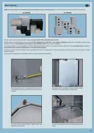
introduction to the catalogue - Ilme SpA
introduction to the catalogue - Ilme SpA
introduction to the catalogue - Ilme SpA

You also want an ePaper? Increase the reach of your titles
YUMPU automatically turns print PDFs into web optimized ePapers that Google loves.
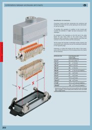
standardsstandardsDimensioning of clearances and creepage distancesEuropean standard EN 61984 Ed. 1.0 (22001-11) was recently publishedfor safety prescriptions for multipole connec<strong>to</strong>rs for industrial uses and for<strong>the</strong> relevant tests. This standard assimilates, without any modifications, <strong>the</strong>corresponding international standard IEC 61984 Ed.1.0 (2001-06).It is applicable <strong>to</strong> connec<strong>to</strong>rs with rated voltage values of over 50V, and up<strong>to</strong> 1000V, and rated currents values of up <strong>to</strong> 125A per pole, for which nodedicated standard exists, or <strong>to</strong> which <strong>the</strong> particular specifications or <strong>the</strong>manufacturer refer as regards <strong>the</strong> safety aspects.For determining <strong>the</strong> minimum through-air and surface insulation distances,i.e. creepage distances, for connec<strong>to</strong>rs, this standard makes use (with somemodifications) of <strong>the</strong> concepts of standard IEC 60664-1 Ed. 1.0 (1992-10) 1) .NOTE - For connec<strong>to</strong>rs with rated voltage values of up <strong>to</strong> 50V - excludedfrom <strong>the</strong> field of application of Low Voltage Directive 73/23/EEC - standardEN 61984 may be used as a guide. For surface and through-air insulationdistances, refer <strong>to</strong> standard IEC 60664-1 Ed. (1992-10).We are illustrating below <strong>the</strong> method of standard EN 61984 for determiningminimum insulation values in connec<strong>to</strong>rs. The rated characteristics for eachILME connec<strong>to</strong>r family are provided on pages 14 and 15.The following are now obsolete: <strong>the</strong> insulation group concept, and <strong>the</strong>distinction of rated voltage values in<strong>to</strong> d.c. and a.c. voltage values 220Vand 380V were adapted <strong>to</strong> standardised values 230V and 400V according<strong>to</strong> IEC 60038 (2) and some concepts were taken from <strong>the</strong> regulations for LVelectrical systems of <strong>the</strong> IEC 60364 (3) series, as follows:- The overvoltage categories (I, II, III, IV), according <strong>to</strong> <strong>the</strong> use of <strong>the</strong>equipment (4) . They are correlated <strong>to</strong> <strong>the</strong> transient overvoltages taken as abasis for determining <strong>the</strong> rated impulse withstand voltage- The degrees of pollution- The classification of insulating materials according <strong>to</strong> <strong>the</strong>ir resistance <strong>to</strong>tracking- The conditions of <strong>the</strong> electrical field (homogenous or inhomogenous).Overvoltage categories (or impulse withstand)The overvoltage categories of a circuit or of an electrical system areidentified by a conventional number (from I <strong>to</strong> IV) based on <strong>the</strong> limit or <strong>the</strong>control of <strong>the</strong> assumed transient overvoltage values obtained on a circuit orelectrical system and depends on <strong>the</strong> means used <strong>to</strong> reduce <strong>the</strong>overvoltages.TABLE 1The rated impulse withstand voltage for equipment energised directly from<strong>the</strong> low-voltage mains (IEC 60664-1 Edition 1.0 1992-10)Nominal voltage of Voltage line <strong>to</strong> neutral Rated impulse withstand<strong>the</strong> supply system derived from nominal voltage b)based on IEC 60038 voltages a.c. or d.c.(CENELEC HD 472 S1, CEI 8-6)Overvoltage categoryV V ≤ V VThree phase a) Single phase I II III IV50 330 500 800 1500100 500 800 1500 2500120-240 150 800 1500 2500 4000230/400277/480} 300 1500 2500 4000 6000400 / 690 600 2500 4000 6000 80001000 1000 4000 6000 8000 12000a) The "/" symbol indicates a four-wire three phase distribution system (star distribution).The lower value is <strong>the</strong> voltage between phase and neutral (phase voltage), whereas <strong>the</strong>higher value is <strong>the</strong> voltage between <strong>the</strong> phases (mains voltage).Where only one value is indicated, it refers <strong>to</strong> three-wire, three-phase systems (deltadistribution) and specifies <strong>the</strong> line-<strong>to</strong>-line value.b) Equipment with <strong>the</strong>se rated impulse withstand values can be used in installations inaccordance with standard IEC 60364-4-443 (Italian standard CEI 64-8/4 Section 443, Germanstandard DIN VDE 0100-443).Table 1 supplies <strong>the</strong> rated impulse withstand voltage for equipment energiseddirectly from <strong>the</strong> low voltage mains in function of <strong>the</strong> rated voltage of <strong>the</strong> powersupply system, <strong>the</strong> relative voltage line-<strong>to</strong>-neutral and <strong>the</strong> overvoltage category.Industrial machinery and installations with fixed connection <strong>to</strong> <strong>the</strong> lowvoltage supply system and consequently <strong>the</strong> relative componentsincluding multipole connec<strong>to</strong>rs, constitute an example of <strong>the</strong> equipmentthat belongs <strong>to</strong> <strong>the</strong> overvoltage category III.Examples of general equipment that comes under overvoltage categoryII are electrical household appliances, portable <strong>to</strong>ols and o<strong>the</strong>r householdequipment or similar.For distribution networks with rated voltage of 230/400V (star distribution wi<strong>the</strong>ar<strong>the</strong>d neutral), and over-voltage category III (category III: impulse withstanding),<strong>the</strong> demanded rated impulse withstanding voltage is 4kV.For distribution networks with rated voltage of 400 or 500V (star distributionwithout neutral or with insulated neutral, or delta distribution, insulated orcorner-ear<strong>the</strong>d), and over-voltage category III (category III: impulse withstanding),<strong>the</strong> demanded rated impulse withstanding voltage is 6kV.(1) Assimilated with modifications as European Harmonisation Document HD 625.1 S1:1996and published by <strong>the</strong> CENELEC member countries as a national standard: Italian standardCEI 28-6 (1997-11), German standard DIN VDE 0110-1 (VDE 0110 Teil 1):1997-04.(2) Harminisation Document CENELEC HD 472 S1, Italian standard CEI 8-6, Germanstandard DIN IEC 38:1987-05.(3) Italian standard CEI 64-8, German standard DIN VDE 0100.(4) HD 625.1 S1 modifies <strong>the</strong> definition <strong>to</strong> "impulse withstanding categories".Degrees of pollutionPollution indicates <strong>the</strong> presence of any kind of foreign matter, whe<strong>the</strong>r solid,liquid or gaseous (ionised gas) that can have a negative influence on <strong>the</strong>dielectric strength or on <strong>the</strong> surface resistivity of <strong>the</strong> insulating material.The standard establishes four degrees of pollution. The categories areidentified by conventional numbers based on <strong>the</strong> quantity of pollutingagents or on <strong>the</strong> frequency of <strong>the</strong> phenomenon which determines <strong>the</strong>reduction of <strong>the</strong> dielectric strength and/or of <strong>the</strong> surface resistivity.Pollution degree 1:No pollution or only dry, non-conductive pollution.The pollution has no influence.Pollution degree 2:Only non-conductive pollution except that occasionally a temporaryconductivity caused by condensation may occur.Pollution degree 3:Conductive pollution or dry, non-conductive pollution which becomesconductive due <strong>to</strong> condensation which may occur.Pollution degree 4:The pollution generates persistent conductivity caused by conductive dus<strong>to</strong>r by rain or snow.Pollution degree 3 is typical of an industrial environment or similar, whilepollution degree 2 is typical of a household environment or similar.Standard EN 61984 permits <strong>the</strong> sizing of surface insulation distances ofconnec<strong>to</strong>rs installed in enclosures in protection class ≥IP54 for <strong>the</strong> degreeof pollution immediately below that of <strong>the</strong> application environment (e.g.: 2instead of 3).Extract from standard EN 619846.19.2.2 For a connec<strong>to</strong>r in protection class IP54 or higher, according <strong>to</strong>Publication IEC 60529, <strong>the</strong> insulating parts inside <strong>the</strong> enclosure may besized for a lower degree of pollution.This applies also <strong>to</strong> coupled connec<strong>to</strong>rs, closure of which is ensured by <strong>the</strong>connec<strong>to</strong>r enclosure, and which may be uncoupled for test and maintenancepurposes only.One may <strong>the</strong>refore use connec<strong>to</strong>rs installed in enclosures or containers inprotection class ≥IP54, at <strong>the</strong> rated data referring <strong>to</strong> degree pollution 2 inindustrial applications with degree of pollution 3, if, in compliance with <strong>the</strong>standard, <strong>the</strong> coupling of <strong>the</strong> connec<strong>to</strong>rs is opened only occasionally fortests or maintenance. In <strong>the</strong> event of temporary or limited duration inuncoupled state, a closing cover is, however, necessary, guaranteeing atleast protection class IP54. However, this does not apply <strong>to</strong> connec<strong>to</strong>rswhich remain uncoupled and exposed <strong>to</strong> an industrial atmosphere for anindefinite period. It should be noted, however, that pollution could penetrateinside coupled connec<strong>to</strong>rs, also when it comes from remote parts of <strong>the</strong>electrical system (e.g. through conduits providing cable entry <strong>to</strong> <strong>the</strong>connec<strong>to</strong>rs enclosure).Moreover, connec<strong>to</strong>r enclosures are usually supplied without cable entrydevices, with <strong>the</strong> installer fitting such devices according <strong>to</strong> need. Thedegree of protection marked on <strong>the</strong> enclosures is guaranteed only forconnec<strong>to</strong>rs coupled through <strong>the</strong> use of cable entry devices in equal orhigher IP protection class and expertly installed.Examples of application for <strong>the</strong> selection of degree of pollution 2 fora connec<strong>to</strong>r- connec<strong>to</strong>r on an electric mo<strong>to</strong>r controller, which is uncoupled only <strong>to</strong> replacea faulty mo<strong>to</strong>r, also in cases where degree of pollution 3 is insteadspecified for <strong>the</strong> system;- connec<strong>to</strong>r on a module-constructed machine, which is opened only fortransport purposes and which is used only for faster installation and forsafer putting in<strong>to</strong> service. One must make sure that <strong>the</strong> connec<strong>to</strong>r has notbeen polluted during transport. To ensure this has not occurred, protectivecovers or adequate packing must be used;- connec<strong>to</strong>r inside a panel in protection class ≥IP54. In this case one mayeven renounce equipping <strong>the</strong> connec<strong>to</strong>r with an IP54 enclosure.Insulating materialInsulating material influences <strong>the</strong> determination of <strong>the</strong> minimum creepagedistance. It is characterised according <strong>to</strong> <strong>the</strong> damage it suffers from <strong>the</strong>concentrated release of energy during scintillations when a surface leakagecurrent is interrupted due <strong>to</strong> <strong>the</strong> drying of <strong>the</strong> contaminated surface.The CTI (comparative tracking index), (index of resistance <strong>to</strong> surfacecurrents) is assumed as index of <strong>the</strong> resistance <strong>to</strong> creep currents of <strong>the</strong>insulating materials in <strong>the</strong> presence of atmospheric contaminating agents.The CTI constitutes <strong>the</strong> numeric value of <strong>the</strong> maximum voltage at which amaterial can resist against 50 drops of an electrolytic test solution withouttracking, i.e. without a progressive formation of conductive paths on <strong>the</strong>surface of <strong>the</strong> solid insulating material (and permanent electric arc between<strong>the</strong> electrodes of <strong>the</strong> test equipment) due <strong>to</strong> <strong>the</strong> combined effect ofelectrical stress and electrolytic contamination.The solid insulating materials are classified in<strong>to</strong> four groups:Group I 600 ≤ CTIGroup II 400 ≤ CTI < 600Group IIIa 175 ≤ CTI < 400Group IIIb 100 ≤ CTI < 175The values for groups IIIa/IIIb (Table 6, EN 61984) are identical for <strong>the</strong>purpose of determining <strong>the</strong> creepage distance values.The insulating materials used <strong>to</strong> manufacture <strong>the</strong> ILME multipoleconnec<strong>to</strong>rs belong <strong>to</strong> groups IIIa / IIIb.10