introduction to the catalogue - Ilme SpA
introduction to the catalogue - Ilme SpA
introduction to the catalogue - Ilme SpA

You also want an ePaper? Increase the reach of your titles
YUMPU automatically turns print PDFs into web optimized ePapers that Google loves.
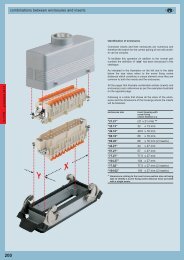
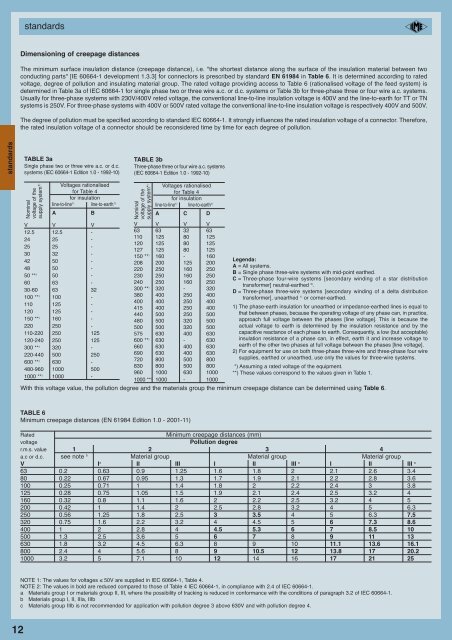
standardsDimensioning of creepage distancesThe minimum surface insulation distance (creepage distance), i.e. "<strong>the</strong> shortest distance along <strong>the</strong> surface of <strong>the</strong> insulation material between twoconducting parts" [IE 60664-1 development 1.3.3] for connec<strong>to</strong>rs is prescribed by standard EN 61984 in Table 6. It is determined according <strong>to</strong> ratedvoltage, degree of pollution and insulating material group. The rated voltage providing access <strong>to</strong> Table 6 (rationalised voltage of <strong>the</strong> feed system) isdetermined in Table 3a of IEC 60664-1 for single phase two or three wire a.c. or d.c. systems or Table 3b for three-phase three or four wire a.c. systems.Usually for three-phase systems with 230V/400V reted voltage, <strong>the</strong> conventional line-<strong>to</strong>-line insulation voltage is 400V and <strong>the</strong> line-<strong>to</strong>-earth for TT or TNsystems is 250V. For three-phase systems with 400V or 500V rated voltage <strong>the</strong> conventional line-<strong>to</strong>-line insulation voltage is respectively 400V and 500V.The degree of pollution must be specified according <strong>to</strong> standard IEC 60664-1. It strongly influences <strong>the</strong> rated insulation voltage of a connec<strong>to</strong>r. Therefore,<strong>the</strong> rated insulation voltage of a connec<strong>to</strong>r should be reconsidered time by time for each degree of pollution.standardsTABLE 3aSingle phase two or three wire a.c. or d.c.systems (IEC 60664-1 Edition 1.0 - 1992-10)TABLE 3bThree-phase three or four wire a.c. systems(IEC 60664-1 Edition 1.0 - 1992-10)Nominalvoltage of <strong>the</strong>supply system* )Voltages rationalisedfor Table 4for insulationline-<strong>to</strong>-line 1) line-<strong>to</strong>-earth 1)ABV V V12.5 12.5 -24 25 -25 25 -30 32 -42 50 -48 50 -50 ** ) 50 -60 63 -30-60 63 32100 ** ) 100 -110 125 -120 125 -150 ** ) 160 -220 250 -110-220 250 125120-240 250 125300 ** ) 320 -220-440 500 250600 ** ) 630 -480-960 1000 5001000 ** ) 1000 -Nominalvoltage of <strong>the</strong>supply system* )Voltages rationalisedfor Table 4for insulationline-<strong>to</strong>-line 1) line-<strong>to</strong>-earth 1)A C DV V V V63 63 32 63110 125 80 125120 125 80 125127 125 80 125150 ** ) 160 - 160208 200 125 200220 250 160 250230 250 160 250240 250 160 250300 ** ) 320 - 320380 400 250 400400 400 250 400415 400 250 400440 500 250 500480 500 320 500500 500 320 500575 630 400 630600 ** ) 630 - 630660 630 400 630690 630 400 630720 800 500 800830 800 500 800960 1000 630 10001000 ** ) 1000 - 1000Legenda:A = All systems.B = Single phase three-wire systems with mid-point ear<strong>the</strong>d.C = Three-phase four-wire systems [secondary winding of a star distributiontransformer] neutral-ear<strong>the</strong>d 2) .D = Three-phase three-wire systems [secondary winding of a delta distributiontransformer], unear<strong>the</strong>d 1) or corner-ear<strong>the</strong>d.1) The phase-earth insulation for unear<strong>the</strong>d or impedance-ear<strong>the</strong>d lines is equal <strong>to</strong>that between phases, because <strong>the</strong> operating voltage of any phase can, in practice,approach full voltage between <strong>the</strong> phases [line voltage]. This is because <strong>the</strong>actual voltage <strong>to</strong> earth is determined by <strong>the</strong> insulation resistance and by <strong>the</strong>capacitive reactance of each phase <strong>to</strong> earth. Consequently, a low (but acceptable)insulation resistance of a phase can, in effect, earth it and increase voltage <strong>to</strong>earth of <strong>the</strong> o<strong>the</strong>r two phases at full voltage between <strong>the</strong> phases [line voltage].2) For equipment for use on both three-phase three-wire and three-phase four wiresupplies, ear<strong>the</strong>d or unear<strong>the</strong>d, use only <strong>the</strong> values for three-wire systems.*) Assuming a rated voltage of <strong>the</strong> equipment.**) These values correspond <strong>to</strong> <strong>the</strong> values given in Table 1.With this voltage value, <strong>the</strong> pollution degree and <strong>the</strong> materials group <strong>the</strong> minimum creepage distance can be determined using Table 6.TABLE 6Minimum creepage distances (EN 61984 Edition 1.0 - 2001-11)RatedMinimum creepage distances (mm)voltagePollution degreer.m.s. value 1 2 3 4a.c or d.c. see note b Material group Material group Material groupV I a II III I II III c I II III c63 0.2 0.63 0.9 1.25 1.6 1.8 2 2.1 2.6 3.480 0.22 0.67 0.95 1.3 1.7 1.9 2.1 2.2 2.8 3.6100 0.25 0.71 1 1.4 1.8 2 2.2 2.4 3 3.8125 0.28 0.75 1.05 1.5 1.9 2.1 2.4 2.5 3.2 4160 0.32 0.8 1.1 1.6 2 2.2 2.5 3.2 4 5200 0.42 1 1.4 2 2.5 2.8 3.2 4 5 6.3250 0.56 1.25 1.8 2.5 3 3.5 4 5 6.3 7.5320 0.75 1.6 2.2 3.2 4 4.5 5 6 7.3 8.6400 1 2 2.8 4 4.5 5.3 6 7 8.5 10500 1.3 2.5 3.6 5 6 7 8 9 11 13630 1.8 3.2 4.5 6.3 8 9 10 11.1 13.6 16.1800 2.4 4 5.6 8 9 10.5 12 13.8 17 20.21000 3.2 5 7.1 10 12 14 16 17 21 25NOTE 1: The values for voltages ≤ 50V are supplied in IEC 60664-1, Table 4.NOTE 2: The values in bold are reduced compared <strong>to</strong> those of Table 4 IEC 60664-1, in compliance with 2.4 of IEC 60664-1.a Materials group I or materials group II, III, where <strong>the</strong> possibility of tracking is reduced in conformance with <strong>the</strong> conditions of paragraph 3.2 of IEC 60664-1.b Materials group I, II, IIIa, IIIbc Materials group IIIb is not recommended for application with pollution degree 3 above 630V and with pollution degree 4.12