introduction to the catalogue - Ilme SpA
introduction to the catalogue - Ilme SpA
introduction to the catalogue - Ilme SpA

You also want an ePaper? Increase the reach of your titles
YUMPU automatically turns print PDFs into web optimized ePapers that Google loves.
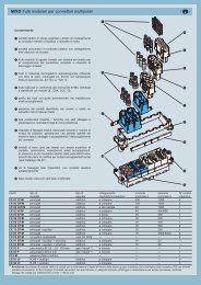
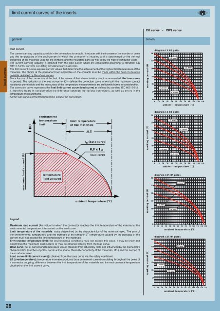
limit current curves of <strong>the</strong> insertsCK series - CKS seriesgeneralcurvesload curvesload curvesThe current carrying capacity possible in <strong>the</strong> connec<strong>to</strong>rs is variable. It reduces with <strong>the</strong> increase of <strong>the</strong> number of polesand <strong>the</strong> temperature of <strong>the</strong> environment in which <strong>the</strong> connec<strong>to</strong>r is installed and is determined by <strong>the</strong> <strong>the</strong>rmalproperties of <strong>the</strong> materials used for <strong>the</strong> contacts and <strong>the</strong> insulating parts as well as by <strong>the</strong> type of conduc<strong>to</strong>r used.The current carrying capacity is obtained from <strong>the</strong> load curves which are constructed according <strong>to</strong> standard IEC60512-5-2 for currents circulating simultaneously in all poles.The limit current curves express current values that determine <strong>the</strong> achievement of <strong>the</strong> highest limit temperature of <strong>the</strong>materials. The choice of <strong>the</strong> permanent load applicable on <strong>the</strong> contacts must be made within <strong>the</strong> field of operationpossible delimited by <strong>the</strong> above curves.Since <strong>the</strong> use of <strong>the</strong> connec<strong>to</strong>rs at <strong>the</strong> limit of <strong>the</strong> values of <strong>the</strong>ir characteristics is not recommended, <strong>the</strong> base curveis derated. The reduction of <strong>the</strong> load curves <strong>to</strong> 80% defines <strong>the</strong> correction curve where both <strong>the</strong> maximum contactresistance permissible and <strong>the</strong> inaccuracy of <strong>the</strong> temperature measurements are sufficiently borne in consideration.The correction curve represents <strong>the</strong> final limit current curve (load curve) as defined by standard IEC 60512-5-2.It <strong>the</strong>refore bears in consideration <strong>the</strong> difference between <strong>the</strong> various connec<strong>to</strong>rs, as well as errors in <strong>the</strong>temperature measurements.All <strong>the</strong> load curves presented herebelow include <strong>the</strong> corrections.working current (A)3025201510500diagram CK 03 poles1,0 mm 2 1,5 mm 2 2,5 mm 20,5 mm 210 20 30 40 50 60 70 80 90 100 110ambient temperature (°C)diagram CK 04 polesenvironment30I (A)temperaturelimitlimit temperatureof <strong>the</strong> materialsTI n (base curve)0,8 x I nworking current (A)252015101,0 mm 2 1,5 mm 2 2,5 mm 2maximum load current (A)temperaturefield allowedload curveambient temperature (°C)working current (A)50030252015100,5 mm 210 20 30 40 50 60 70 80 90 100 110ambient temperature (°C)diagram CKS 03 poles1,5 mm 2 2,5 mm 21,0 mm 2Legend:Maximum load current (A): value for which <strong>the</strong> connec<strong>to</strong>r reaches <strong>the</strong> limit temperature of <strong>the</strong> material at <strong>the</strong>environmental temperature, intersected on <strong>the</strong> load curve.Limit temperature of <strong>the</strong> materials: value determined by <strong>the</strong> characteristics of <strong>the</strong> materials used. The sum of<strong>the</strong> environmental temperature and <strong>the</strong> increase of <strong>the</strong> simbolo ΔT temperature caused by <strong>the</strong> passage of <strong>the</strong>current must not exceed <strong>the</strong> limit temperature of <strong>the</strong> materials.Environment temperature limit: <strong>the</strong> environmental conditions must not exceed this value. It may be know anddetermines <strong>the</strong> maximum load current, or may be obtained directly from <strong>the</strong> load curve.Base curve: set of current and temperature values obtained from labora<strong>to</strong>ry tests and influenced by <strong>the</strong> connec<strong>to</strong>r’scharacteristics (number of poles, construction shape, <strong>the</strong>rmal conductivity of <strong>the</strong> materials, etc.) and <strong>the</strong> section of<strong>the</strong> conduc<strong>to</strong>r used.Load curve (limit current curve): obtained from <strong>the</strong> base curve via <strong>the</strong> safety coefficient.ΔT (overtemperature): temperature increase produced by a permanent current circulating through all <strong>the</strong> poles ofa connec<strong>to</strong>r coupling; difference between <strong>the</strong> limit temperature of <strong>the</strong> materials and <strong>the</strong> environmental temperatureobtained on <strong>the</strong> limit current curve.working current (A)50010 20 30 40 50 60 70 80 90 100 110 120 130ambient temperature (°C)diagram CKS 04 poles30252015101,5 mm 2 2,5 mm 21,0 mm 250010 20 30 40 50 60 70 80 90 100 110 120 130ambient temperature (°C)28