Series 90 Electrical Displacement Control (EDC ... - Sauer-Danfoss
Series 90 Electrical Displacement Control (EDC ... - Sauer-Danfoss
Series 90 Electrical Displacement Control (EDC ... - Sauer-Danfoss

You also want an ePaper? Increase the reach of your titles
YUMPU automatically turns print PDFs into web optimized ePapers that Google loves.
Description/<br />
Theory of Operation<br />
<strong>Series</strong> <strong>90</strong> <strong>Electrical</strong> <strong>Displacement</strong> <strong>Control</strong> (<strong>EDC</strong>)<br />
Product <strong>Electrical</strong> Installation Technical Information<br />
Product Overview<br />
The electric displacement control uses an electrohydraulic Pressure <strong>Control</strong> Pilot (PCP)<br />
valve to control the pilot pressure. The PCP converts an electrical input signal to a<br />
hydraulic input signal to operate a 4-way servo valve, which ports hydraulic pressure to<br />
either side of a double acting servo piston. The servo piston tilts the cradle swashplate,<br />
thus varying the pump’s displacement from full displacement in one direction to full<br />
displacement in the opposite direction.<br />
The control has a mechanical feedback mechanism which moves the servo valve in<br />
relation to the input signal and the angular position of the swashplate. The electrical<br />
displacement control is designed so the angular rotation of the swashplate (pump<br />
displacement) is proportional to the electrical input signal. Due to normal operating<br />
force changes, the swashplate tends to drift from the position preset by the machine<br />
operator. Drift, sensed by feedback linkage system connecting the swashplate to the<br />
control valve, will activate the valve and supply pressure to the servo piston, maintaining<br />
the swashplate in its preset position.<br />
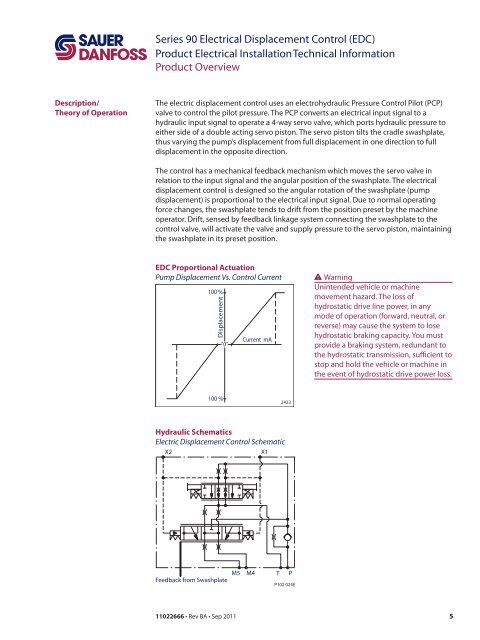
<strong>EDC</strong> Proportional Actuation<br />
Pump <strong>Displacement</strong> Vs. <strong>Control</strong> Current<br />
100 %<br />
<strong>Displacement</strong><br />
100 %<br />
"0"<br />
11022666 • Rev BA • Sep 2011<br />
Current mA<br />
Hydraulic Schematics<br />
Electric <strong>Displacement</strong> <strong>Control</strong> Schematic<br />
X2 X1<br />
Feedback from Swashplate<br />
2423<br />
M5 M4 T P<br />
P102 024E<br />
WWarning<br />
Unintended vehicle or machine<br />
movement hazard. The loss of<br />
hydrostatic drive line power, in any<br />
mode of operation (forward, neutral, or<br />
reverse) may cause the system to lose<br />
hydrostatic braking capacity. You must<br />
provide a braking system, redundant to<br />
the hydrostatic transmission, sufficient to<br />
stop and hold the vehicle or machine in<br />
the event of hydrostatic drive power loss.<br />
5