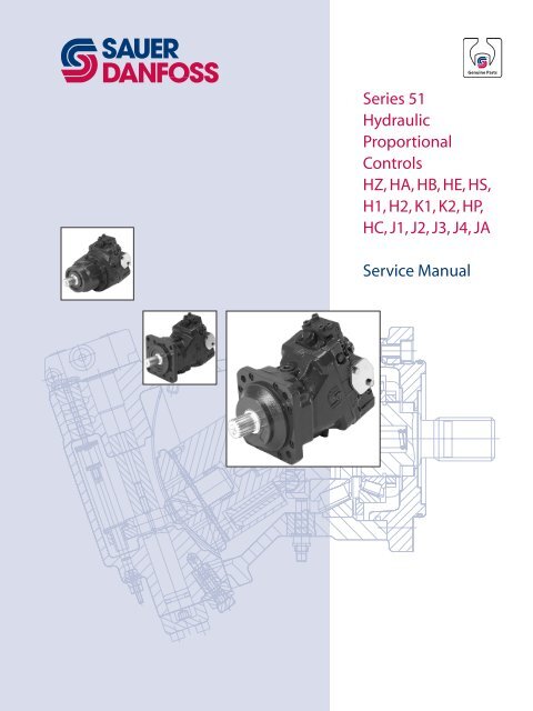
Series 51 Hydraulic Proportional Controls HZ, HA ... - Sauer-Danfoss
Series 51 Hydraulic Proportional Controls HZ, HA ... - Sauer-Danfoss
Series 51 Hydraulic Proportional Controls HZ, HA ... - Sauer-Danfoss

You also want an ePaper? Increase the reach of your titles
YUMPU automatically turns print PDFs into web optimized ePapers that Google loves.
<strong>Series</strong> <strong>51</strong><br />
<strong>Hydraulic</strong><br />
<strong>Proportional</strong><br />
<strong>Controls</strong><br />
<strong>HZ</strong>, <strong>HA</strong>, HB, HE, HS,<br />
H1, H2, K1, K2, HP,<br />
HC, J1, J2, J3, J4, JA<br />
Service Manual
History of Revisions<br />
<strong>Series</strong> <strong>51</strong> <strong>Hydraulic</strong> <strong>Proportional</strong> <strong>Controls</strong><br />
Service Manual<br />
Revisions<br />
© 2010 <strong>Sauer</strong>-<strong>Danfoss</strong>. All rights reserved.<br />
<strong>Sauer</strong>-<strong>Danfoss</strong> accepts no responsibility for possible errors in catalogs, brochures and other printed material.<br />
<strong>Sauer</strong>-<strong>Danfoss</strong> reserves the right to alter its products without prior notice. This also applies to products<br />
already ordered provided that such alterations aren’t in conflict with agreed specifications. All trademarks in<br />
this material are properties of their respective owners. <strong>Sauer</strong>-<strong>Danfoss</strong> and the <strong>Sauer</strong>-<strong>Danfoss</strong> logotype are<br />
trademarks of the <strong>Sauer</strong>-<strong>Danfoss</strong> Group.<br />
2 11009446 • Rev AC • November 2010<br />
Table of Revisions<br />
Date Page Changed Rev.<br />
November 2010 last new last page AC<br />
February 2010 last Fix Osaka address AB<br />
July 2009 - First edition AA
Introduction<br />
Pressure measurements<br />
Adjustments<br />
PCOR<br />
Multifunction block<br />
<strong>HZ</strong>, <strong>HA</strong>, HB, HE <strong>Controls</strong><br />
<strong>Series</strong> <strong>51</strong> <strong>Hydraulic</strong> <strong>Proportional</strong> <strong>Controls</strong><br />
Service Manual<br />
Contents<br />
Safety Precautions.......................................................................................................................................... 5<br />
Unintended Machine Movement ........................................................................................................ 5<br />
Flammable Cleaning Solvents .............................................................................................................. 5<br />
Fluid Under Pressure ................................................................................................................................ 5<br />
Personal Safety .......................................................................................................................................... 5<br />
Hazardous Material .................................................................................................................................. 5<br />
Symbols used in <strong>Sauer</strong>-<strong>Danfoss</strong> Literature ........................................................................................... 6<br />
Overview ........................................................................................................................................................... 7<br />
General Instructions ...................................................................................................................................... 7<br />
Keep it Clean ............................................................................................................................................... 7<br />
Inspect for System Contamination ..................................................................................................... 7<br />
Replace the O-rings and Gaskets ........................................................................................................ 7<br />
Lubricate all Moving Parts ..................................................................................................................... 7<br />
Torque Procedure ..................................................................................................................................... 7<br />
General Description....................................................................................................................................... 8<br />
Overview ...................................................................................................................................................... 8<br />
Threshold and Ramp Springs ............................................................................................................... 8<br />
Multiblock .................................................................................................................................................... 9<br />
Pressure Compensator OverRide (PCOR) Function ....................................................................10<br />
Brake Pressure Defeat (BPD) Option ................................................................................................10<br />
Port locations and Gauge Installation ..................................................................................................11<br />
Threshold Setting .........................................................................................................................................12<br />
Checking Threshold Setting ................................................................................................................12<br />
Adjusting Threshold Setting ...............................................................................................................12<br />
Pressure Compensator OverRide (PCOR) Setting .............................................................................13<br />
PCOR Adjustment ...................................................................................................................................13<br />
Checking PCOR Setting on a Test Stand .........................................................................................13<br />
Adjusting the PCOR Setting ................................................................................................................13<br />
Optional PCOR Housing .............................................................................................................................14<br />
Optional Multifunction block .................................................................................................................16<br />
Operation ........................................................................................................................................................18<br />
Functional Description .........................................................................................................................18<br />
<strong>HZ</strong> Control .................................................................................................................................................18<br />
<strong>HA</strong> and HB <strong>Controls</strong> ...............................................................................................................................18<br />
HE Control..................................................................................................................................................18<br />
Repair ................................................................................................................................................................19<br />
11009446 • Rev AC • November 2010<br />
3
<strong>Series</strong> <strong>51</strong> <strong>Hydraulic</strong> <strong>Proportional</strong> <strong>Controls</strong><br />
Service Manual<br />
Contents<br />
HS Control Operation ........................................................................................................................................................21<br />
Functional Description .........................................................................................................................21<br />
Repair ................................................................................................................................................................22<br />
H1, H2, K1, K2 <strong>Controls</strong><br />
HP Control<br />
HC Control<br />
J1, J2, J3, J4 <strong>Controls</strong><br />
JA Control<br />
Operation ........................................................................................................................................................23<br />
Functional Description .........................................................................................................................23<br />
Solenoid Valve ..........................................................................................................................................23<br />
Repair ................................................................................................................................................................24<br />
Operation ........................................................................................................................................................26<br />
Functional Description .........................................................................................................................26<br />
HP Control .................................................................................................................................................26<br />
Shuttle Valve .............................................................................................................................................26<br />
Connecting Pin ........................................................................................................................................26<br />
Repair ................................................................................................................................................................27<br />
Operation ........................................................................................................................................................29<br />
Functional Description .........................................................................................................................29<br />
Check Valve ...............................................................................................................................................29<br />
Shuttle Valve .............................................................................................................................................29<br />
Connecting Pin ........................................................................................................................................29<br />
Repair ................................................................................................................................................................30<br />
Operation ........................................................................................................................................................33<br />
Functional Description .........................................................................................................................33<br />
Solenoid Valve ..........................................................................................................................................33<br />
Repair ................................................................................................................................................................34<br />
Operation ........................................................................................................................................................37<br />
Functional Description .........................................................................................................................37<br />
Signal Pressure .........................................................................................................................................37<br />
Repair ................................................................................................................................................................38<br />
4 11009446 • Rev AC • November 2010
Safety Precautions<br />
<strong>Series</strong> <strong>51</strong> <strong>Hydraulic</strong> <strong>Proportional</strong> <strong>Controls</strong><br />
Service Manual<br />
Introduction<br />
Always consider safety precautions before beginning a service procedure. Protect<br />
yourself and others from injury. Take the following general precautions whenever servicing a<br />
hydraulic system.<br />
Unintended Machine Movement<br />
W Warning<br />
Unintended movement of the machine or mechanism may cause injury to the technician<br />
or bystanders. To protect against unintended movement, secure the machine or disable/<br />
disconnect the mechanism while servicing.<br />
Flammable Cleaning Solvents<br />
W Warning<br />
Some cleaning solvents are flammable. To avoid possible fire, do not use cleaning<br />
solvents in an area where a source of ignition may be present.<br />
Fluid Under Pressure<br />
W Warning<br />
Escaping hydraulic fluid under pressure can have sufficient force to penetrate your skin<br />
causing serious injury and/or infection. This fluid may also be hot enough to cause burns.<br />
Use caution when dealing with hydraulic fluid under pressure. Relieve pressure in the<br />
system before removing hoses, fittings, gauges, or components. Never use your hand<br />
or any other body part to check for leaks in a pressurized line. Seek medical attention<br />
immediately if you are cut by hydraulic fluid.<br />
Personal Safety<br />
W Warning<br />
Protect yourself from injury. Use proper safety equipment, including safety glasses, at all<br />
times.<br />
Hazardous Material<br />
W Warning<br />
<strong>Hydraulic</strong> fluid contains hazardous material. Avoid prolonged contact with hydraulic fluid.<br />
Always dispose of used hydraulic fluid acm³ording to state, and federal environmental<br />
regulations.<br />
11009446 • Rev AC • November 2010<br />
5
Symbols used in <strong>Sauer</strong>-<br />
<strong>Danfoss</strong> Literature<br />
<strong>Series</strong> <strong>51</strong> <strong>Hydraulic</strong> <strong>Proportional</strong> <strong>Controls</strong><br />
Service Manual<br />
Introduction<br />
These symbols are in the illustrations and text of this manual. They communicate helpful<br />
information at the point where it is most useful to the reader.<br />
In most instances, the appearance of the symbol itself denotes its meaning. The legend<br />
to the right of each symbol defines the symbol and explain its purpose.<br />
� May result in injury.<br />
� CAUTION may result in damage to<br />
product or property<br />
� Dispose; nonreusable part. Use a<br />
new part.<br />
� External hex.<br />
� Internal hex wrench<br />
6 11009446 • Rev AC • November 2010<br />
� Lubricate.<br />
� Apply grease / petroleum jelly.<br />
� Inspect for wear or damage.<br />
� Clean area or part.<br />
� Torque specification.<br />
� Option
Overview<br />
General Instructions<br />
<strong>Series</strong> <strong>51</strong> <strong>Hydraulic</strong> <strong>Proportional</strong> <strong>Controls</strong><br />
Service Manual<br />
Introduction<br />
This manual includes information for the installation, maintenance, and minor repair<br />
of <strong>Series</strong> <strong>51</strong> hydraulic proportional controls. It includes a description of the unit and its<br />
individual components, and minor repair procedures.<br />
Performing minor repairs may require removal of the unit from the vehicle/machine.<br />
Thoroughly clean the unit before beginning maintenance, or repair activities. Since dirt<br />
and contamination are the greatest enemies of any type of hydraulic equipment, follow<br />
cleanliness requirements strictly. This is especially important when changing the system<br />
filter and when removing hoses or plumbing.<br />
A worldwide network of <strong>Sauer</strong>-<strong>Danfoss</strong> Global Service Partners is available for major<br />
repairs. <strong>Sauer</strong>-<strong>Danfoss</strong> Global Service Partners are trained by the factory and certified on<br />
a regular basis. You can locate your nearest Global Service Partner using the distributor<br />
locator at www.sauer-danfoss.com. Click on the Sales and Service link.<br />
Keep it Clean<br />
You can complete many repairs or adjustments without removing the unit from the<br />
machine, if the unit is accessible and you can thoroughly clean it before beginning any<br />
procedures.<br />
Cleanliness is a primary means of assuring satisfactory motor life on either new or<br />
repaired units. Clean the outside of the motor thoroughly before disassembly. Take care to<br />
avoid contamination of the system ports. Cleaning parts with a clean solvent wash and<br />
air drying is usually adequate.<br />
As with any precision equipment, keep all parts free of foreign materials and chemicals.<br />
Protect all exposed sealing surfaces and open cavities from damage and foreign material.<br />
Cap all hoses after removal, and plug all open ports. Cover any unattended parts with a<br />
protective layer of plastic.<br />
Inspect for System Contamination<br />
Inspect the motor for signs of system contamination. If you find contamination, fully<br />
disassemble, clean and inspect all components of the motor.<br />
Replace the O-rings and Gaskets<br />
Replace all O-rings and gaskets. Discard them only after you make certain that you have<br />
the correct replacement parts. Lightly lubricate all O-rings with clean petroleum jelly<br />
before assembly.<br />
Lubricate all Moving Parts<br />
During reassembly, coat all moving parts with a film of clean hydraulic oil. This helps<br />
lubricate the surfaces during start-up.<br />
For fluid quality requirements, refer to 520L0463 <strong>Hydraulic</strong> Fluids and Lubricants,<br />
Technical Information.<br />
Torque Procedure<br />
During reassembly, cross torque all retaining screws to the given value. Do not<br />
overtorque.<br />
11009446 • Rev AC • November 2010<br />
7
<strong>Series</strong> <strong>51</strong> <strong>Hydraulic</strong> <strong>Proportional</strong> <strong>Controls</strong><br />
Service Manual<br />
Introduction<br />
General Description Overview<br />
<strong>Hydraulic</strong> proportional controls infinitely vary the motor displacement between<br />
maximum and minimum by feeding a variable hydraulic signal pressure to the end of<br />
the 4-way valve directly, or to a piston that moves the 4-way valve As signal-pressure<br />
shifts the 4-way valve, it ports pressure to the ends of the servo piston, changing motor<br />
displacement. A threshold spring and a ramp spring act on the opposite end of the<br />
4-way valve.<br />
Ramp spring(s)<br />
Threshold and Ramp Springs<br />
The threshold adjustment screw varies the threshold spring force required to move the<br />
4-way valve and start the change in displacement. The ramp spring(s)—2 used in 160cc<br />
and 250cc motors, and one used in the 80 cc and 110cc motors—increase the force on<br />
the 4-way valve as the servo piston moves toward minimum displacement. This provides<br />
a motor displacement proportional to the input signal pressure.<br />
The control operating threshold (the signal pressure when the motor starts to shift) is<br />
adjustable. Adjust it using the adjusting screw in the end cap.<br />
Changing ramp spring force requires replacing the springs. There are several spring rates<br />
available.<br />
Optional orifices may be installed at several locations to regulate shift speed. Refer to the<br />
Model Code for your motor for details.<br />
Threshold and Ramp Springs<br />
Spring seat<br />
S10*<br />
S10* S20<br />
Threshold spring<br />
Spring seat<br />
8 11009446 • Rev AC • November 2010<br />
S10<br />
J30<br />
P106 438E<br />
Threshold adjustment screw<br />
J50<br />
locknut
General Description<br />
(continued)<br />
<strong>Series</strong> <strong>51</strong> <strong>Hydraulic</strong> <strong>Proportional</strong> <strong>Controls</strong><br />
Service Manual<br />
Introduction<br />
Multiblock<br />
Some hydraulic proportional controls are used in conjunction with the multiblock. The<br />
multiblock is a manifold with a shuttle-valve that routes high loop (system pressure)<br />
from port A or port B to the 4-way valve to serve as servo supply and to the PCOR<br />
function. The shuttle valve also routes the low pressure side of the loop to the PCOR<br />
function.<br />
Multifunction Schematic<br />
PCOR Valve<br />
BPD Spool<br />
U7<br />
T5<br />
11009446 • Rev AC • November 2010<br />
U6<br />
T4<br />
T6<br />
A<br />
XA XB B<br />
Multiblock<br />
Shuttle<br />
L2 M4 M3 N<br />
M7 X1<br />
Loop Flush<br />
T2<br />
T1<br />
max.<br />
disp.<br />
T3<br />
T7 T8<br />
Control<br />
4-Way Valve<br />
n<br />
M1<br />
L1<br />
M5<br />
M2<br />
P106 417E<br />
9
General Description<br />
(continued)<br />
<strong>Series</strong> <strong>51</strong> <strong>Hydraulic</strong> <strong>Proportional</strong> <strong>Controls</strong><br />
Service Manual<br />
Introduction<br />
Pressure Compensator OverRide<br />
(PCOR) Function<br />
The Pressure Compensator OverRide<br />
Optional Orifices: T4, T5, T6, U6, U7<br />
(PCOR) function allows the motor to<br />
match its displacement to the system<br />
load. The PCOR overrides the control<br />
command allowing the motor to<br />
increase displacement when system<br />
T4<br />
T5<br />
T6<br />
pressure reaches a set level due to load.<br />
U7<br />
This permits the motor to regulate<br />
system pressure by modulating the<br />
displacement of the rotating group. As<br />
displacement increases, available torque<br />
U6<br />
increases. Output speed decreases and<br />
system pressure remains nearly constant<br />
at the PCOR setting.<br />
P106 415E<br />
The PCOR setting is adjustable from 110 to 370 bar [1595 to 5365 psi]. Optional orifices at<br />
locations T4, T5, T6, U6, and U7 regulate the PCOR operation speed.<br />
Brake Pressure Defeat (BPD) Option<br />
The PCOR function can be equipped with an optional brake pressure defeat (BPD) option<br />
that defeats the PCOR operation during dynamic braking. A shuttle spool ahead of the<br />
PCOR valve directs only acceleration system pressure to the PCOR. During deceleration<br />
the dynamic braking pressure is blocked from the PCOR limiting rapid deceleration,<br />
uncontrolled pressures or engine over-speeding while the vehicle/machine is slowing<br />
down. An external hydraulic signal pressure fed to ports XA or XB are required to operate<br />
the BPD spool. PCOR operation on one system pressure side is also an option.<br />
BPD Option<br />
Shuttle valve<br />
10 11009446 • Rev AC • November 2010<br />
Brake defeat spool<br />
PCOR spool<br />
PCOR adjuster<br />
P106 431E
Port locations and Gauge<br />
Installation<br />
Port Locations<br />
<strong>Series</strong> <strong>51</strong> <strong>Hydraulic</strong> <strong>Proportional</strong> <strong>Controls</strong><br />
Service Manual<br />
Pressure measurements<br />
The following table and drawings show the port locations and gauge sizes needed.<br />
When testing system pressures, calibrate pressure gauges frequently to ensure accuracy.<br />
Use snubbers to protect gauges.<br />
Port Information<br />
Port identifier Port size Wrench size Reading Gauge size, bar [psi]<br />
L1, L2 1 1/16-12 UNF 9/16 internal hex Case drain 10 bar [100 psi]<br />
M1, M2 9/16-18 UNF 1/4 internal hex System pressure 600 bar [10,000 psi]<br />
M3, M4, M5 9/16-18 UNF 1/4 internal hex Servo pressure 50 bar [1000 psi]<br />
X1, M7 9/16-18 UNF 1/4 internal hex Control pressure 50 bar [1000 psi]<br />
Radial ported motor<br />
L2<br />
L1<br />
Axial ported motor<br />
M3<br />
11009446 • Rev AC • November 2010<br />
M3<br />
A<br />
M7<br />
M1+M2<br />
M1 M5<br />
Threshold<br />
adjustment<br />
M7<br />
X1<br />
M5<br />
X1<br />
M1<br />
M3 M5<br />
B A<br />
System port A<br />
M4<br />
M4<br />
M2<br />
M4<br />
System port B<br />
P106 434E<br />
11
<strong>Series</strong> <strong>51</strong> <strong>Hydraulic</strong> <strong>Proportional</strong> <strong>Controls</strong><br />
Service Manual<br />
Adjustments<br />
Threshold Setting Checking Threshold Setting<br />
1. Install a 50 bar [600 psi] gauge at port M3 to read minimum servo pressure.<br />
12 11009446 • Rev AC • November 2010<br />
2. Install a 50 bar [600 psi] gauge at port M4 to read maximum servo pressure.<br />
3. Install meter to read signal current.<br />
4. Increase the signal current to the proper setting.<br />
The pressure at port M3 should rise to about 100 psi [6.89 bar] higher than the pressure<br />
at port M4. This causes the servo piston to move toward minimum position. Signal<br />
current at this point is the threshold setting.<br />
On a test stand, increase signal current until the flow from the motor begins to decrease.<br />
The signal current at this point is the threshold setting.<br />
Adjusting Threshold Setting<br />
1. Using a 10 mm wrench, loosen the<br />
locknut on the adjustment screw.<br />
2. Using a 3 mm internal hex wrench<br />
turn the adjusting screw:<br />
• Clockwise (cw) to increase the<br />
setting<br />
• Counterclockwise (ccw) to<br />
decrease the setting.<br />
3. While holding the position of the<br />
adjustment screw:<br />
• tighten the locknut<br />
• using a 10 mm wrench torque<br />
the locknut to 9 N•m [6.6 lbf•ft].<br />
Locknut and Threshold<br />
Locknut<br />
10 mm<br />
9 Nm [6.6 lbf•ft]<br />
Adjusting screw<br />
Spring seat<br />
P101 911
Pressure Compensator<br />
OverRide<br />
(PCOR) Setting<br />
<strong>Series</strong> <strong>51</strong> <strong>Hydraulic</strong> <strong>Proportional</strong> <strong>Controls</strong><br />
Service Manual<br />
Adjustments<br />
PCOR Adjustment<br />
In order to measure and adjust the start pressure setting for the PCOR function:<br />
1. Install a 600 bar [10000 psi] gauge at port M1 or M2 or M5 to read high system<br />
pressure.<br />
2. Install a 600 bar [10000 psi] gauge at port M3 to read minimum servo pressure.<br />
3. Lock the motor shaft from moving by:<br />
• Applying the park brake, apply an extreme load, or<br />
• Position the machine against an immovable object, or<br />
• Other means to hold the machine.<br />
4. Start the prime mover. Operate at medium RPM.<br />
5. Stroke the pump very slowly to gradually increase the system pressure.<br />
An alternate method to slowly increase the system pressure is to use the pump’s<br />
pressure limiter (PL) valve. Lower the PL setting below the PCOR setting. Stroke the<br />
pump to about one-fourth displacement. Raise the PL setting slowly to increase system<br />
pressure until pressure at the M3 port drops down. System pressure at this point is the<br />
PCOR setting. Adjust the PL back to its proper setting after checking the PCOR setting.<br />
6. Increase system pressure until pressure at port M3 drops down, system pressure at<br />
this point is the PCOR setting.<br />
Checking PCOR Setting on a Test Stand<br />
Increase system pressure until the system flow begins to increase. System pressure at this<br />
point is the PCOR setting.<br />
CCaution<br />
System pressure may increase rapidly when flow increases.<br />
Adjusting the PCOR Setting<br />
• For PCOR valves mounted on a Multiblock; use a 1-1/16 inch wrench to loosen the<br />
lock nut on the adjusting screw. Using a large screw driver or a 13 mm wrench, turn<br />
the adjusting screw clockwise to increase pressure setting or counter clockwise<br />
to lower pressure setting. One turn of the adjusting screw changes the setting<br />
approximately 69 bar [1000 psi].<br />
• For controls using the threshold adjusting screw for PCOR adjustment; use a 10<br />
mm wrench to loosen the locknut. Using a 3 mm wrench, turn the adjusting screw<br />
clockwise to increase pressure or counter clockwise to lower pressure setting. One<br />
turn of the adjusting screw changes the setting approximately 55 bar [800 psi].<br />
11009446 • Rev AC • November 2010<br />
13
<strong>Series</strong> <strong>51</strong> <strong>Hydraulic</strong> <strong>Proportional</strong> <strong>Controls</strong><br />
Service Manual<br />
PCOR<br />
Optional PCOR Housing Disassembly<br />
1. Remove plugs (N27). Remove and discard O-rings (N27A).<br />
14 11009446 • Rev AC • November 2010<br />
2. Using a 1 inch wrench, remove plug (N23). Remove and discard O-ring (N23A).<br />
3. Remove locknut (N14).<br />
4. Remove adjustment plug (Z00). Remove and discard O-ring (N16J).<br />
5. Remove spring (N18).<br />
6. Remove spool and spring guide assembly (N20).<br />
7. Remove screws (N29).<br />
8. Remove and discard O-rings (N24P, N82).<br />
9. If present, remove orifices (U6, U7).<br />
PCOR<br />
Legend<br />
N23<br />
U6 U7<br />
N27<br />
N24P<br />
N82<br />
Item Wrench size Torque<br />
N8 7<br />
N27 1/8 inch internal hex 7 Nm [4 lbf•ft]<br />
N20 N14<br />
N27<br />
N23 1 inch 40 Nm [30 lbf•ft]<br />
U6, U7 3 mm internal hex 6 Nm [4 lbf•ft]<br />
N29 5 mm internal hex 16 Nm [12 lbf•ft]<br />
N14 1-5/16 inch N/A<br />
N18<br />
N29<br />
Z00<br />
P106 384E<br />
Inspection<br />
Clean and inspect components for damage or foreign material. Replace damaged parts.<br />
N16J
Optional PCOR Housing<br />
(continued)<br />
<strong>Series</strong> <strong>51</strong> <strong>Hydraulic</strong> <strong>Proportional</strong> <strong>Controls</strong><br />
Service Manual<br />
PCOR<br />
Assembly<br />
1. If previously removed, use a 3mm internal hex wrench to install orifices (U6, U7).<br />
Torque to 6 N•m [4 lbf•ft].<br />
2. Using petroleum jelly to retain them, install new interface O-rings (N24P, N82).<br />
3. Position PCOR on multiblock. Install screws (N29). Torque using a 5 mm internal hex<br />
wrench to 16 N•m [12 lbf•ft].<br />
4. Lubricate and install spool and spring guide assembly (N20).<br />
5. Install spring (N18) to cavity.<br />
6. Lubricate and install new O-ring (N16J). Install adjustment plug (Z00).<br />
7. Using a 1-1/16 inch hex wrench, install locknut (N14). Do not torque until after PCOR<br />
adjustment. Refer to page 13 for instructions.<br />
8. Lubricate and install a new O-ring (N23A). Using a 1 inch hex wrench, install plug<br />
(N23). Torque to 40 N•m [30 lbf•ft].<br />
9. Lubricate and install new O-rings (N27A). Using a 1/8 inch internal hex wrench, install<br />
and torque plugs (N27) to 7 N•m [4 lbf•ft].<br />
11009446 • Rev AC • November 2010<br />
15
Optional Multifunction<br />
block<br />
<strong>Series</strong> <strong>51</strong> <strong>Hydraulic</strong> <strong>Proportional</strong> <strong>Controls</strong><br />
Service Manual<br />
Multifunction block<br />
Disassembly<br />
1. Using a ¼ inch internal hex wrench, remove plugs (N26). Remove and discard O-rings<br />
(N26A).<br />
2. Remove the spool (N30).<br />
16 11009446 • Rev AC • November 2010<br />
3. Using a 1/8 inch internal hex wrench, remove plugs (N27). Remove and discard<br />
O-rings (N27A).<br />
4. Remove screws (N58).<br />
5. Remove the multifunction block (N1A1).<br />
6. Remove and discard O-rings (G36, G38, and G42) or gasket (N240).<br />
7. If present, remove and discard screens (N52). They are no longer used.<br />
E*, F* Control<br />
N26<br />
Legend<br />
N30<br />
N1A1<br />
N27<br />
N27<br />
G42<br />
G38<br />
N52<br />
G36<br />
G38<br />
G42<br />
G38<br />
Item Wrench size Torque<br />
N27<br />
N26<br />
N27 1/8 inch internal hex 7 Nm [4 lbf•ft]<br />
N26 1/4 inch internal hex 37 Nm [28 lbf•ft]<br />
N58<br />
80cc, 110cc<br />
N58<br />
160cc, 250cc<br />
8 mm internal hex 78 Nm [58 lbf•ft]<br />
10 mm internal hex 110 Nm [81 lbf•ft]<br />
N27<br />
N58 P101210<br />
N240
Optional Multifunction<br />
block<br />
(continued)<br />
<strong>Series</strong> <strong>51</strong> <strong>Hydraulic</strong> <strong>Proportional</strong> <strong>Controls</strong><br />
Service Manual<br />
Multifunction block<br />
Inspection<br />
Clean and inspect components for damage or foreign material. Replace damaged parts.<br />
Assembly<br />
1. Lubricate and install new O-rings (N27A). Install plugs (N27) using a 1/8 inch internal<br />
hex wrench. Torque to 7 N•m [4 lbf•ft].<br />
2. Using petroleum jelly to retain them, install new interface O-rings (G36, G38, G42) or<br />
gasket (N240).<br />
3. Position the multifunction block on the endcap. Install screws (N58). Torque screws<br />
as shown in the table.<br />
4. Lubricate and install the double-resolver spool (N30). The spool is symetrical, either<br />
end in first.<br />
5. Lubricate and install new O-rings (N26A). Using a 1/4 inch internal hex wrench, install<br />
plugs (N26). Torque to 37 N•m [28 lbf•ft].<br />
11009446 • Rev AC • November 2010<br />
17
<strong>Series</strong> <strong>51</strong> <strong>Hydraulic</strong> <strong>Proportional</strong> <strong>Controls</strong><br />
Service Manual<br />
<strong>HZ</strong>, <strong>HA</strong>, HB, HE <strong>Controls</strong><br />
Operation Functional Description<br />
The <strong>HZ</strong>, <strong>HA</strong>, HB, and HE controls consist of a ported housing mounted directly to the<br />
end cap. Variable signal pressure fed to port X1 is routed to the end of the 4-way valve. A<br />
threshold spring and ramp spring(s) act on the opposite end of the 4-way valve.<br />
<strong>HZ</strong> Control<br />
The <strong>HZ</strong> control has a check valve to resolve which port (system A or B) is higher pressure.<br />
It routes this high pressure to the 4-way valve to power the servo piston.<br />
<strong>HA</strong> and HB <strong>Controls</strong><br />
The <strong>HA</strong> and HB controls have internal porting to feed system A or B pressures,<br />
respectively, to the 4-way valve to power the servo piston.<br />
HE Control<br />
The HE control has no internal porting for servo supply pressure. An external servo<br />
supply pressure fed to port M5 is required.<br />
<strong>HZ</strong> Schematic Diagram<br />
18 11009446 • Rev AC • November 2010<br />
A<br />
B<br />
M7<br />
M4 M3<br />
max.<br />
disp.<br />
X1<br />
T2<br />
T1<br />
T3<br />
T7 T8<br />
P107 823<br />
M1<br />
L1<br />
L2<br />
M5<br />
M2
<strong>Series</strong> <strong>51</strong> <strong>Hydraulic</strong> <strong>Proportional</strong> <strong>Controls</strong><br />
Service Manual<br />
<strong>HZ</strong>, <strong>HA</strong>, HB, HE <strong>Controls</strong><br />
Repair Disassembly<br />
1. Remove screws (M22) using a:<br />
• 8 mm internal hex wrench for 80 cc and 110cc motors<br />
• 10 mm internal hex wrench for 160 cc and 250 cc motors.<br />
Legend<br />
2. Remove control block ( M1<strong>HZ</strong>).<br />
3. Remove and discard O-rings (G38, G42, and G36) or gasket (G420).<br />
4. If present, remove plugs (M16) using a ¼ inch internal hex wrench (<strong>HZ</strong> controls only).<br />
5. Remove and discard O-rings ( M16A).<br />
6. If present, remove orifice (M12) using a 5mm internal hex wrench (<strong>HZ</strong> controls only).<br />
7. If present, remove shuttle valve (M10) (<strong>HZ</strong> controls only).<br />
If necessary, tap the housing on a solid surface to remove the shuttle valve.<br />
8. Remove plugs (M18) using a 1/8 inch internal hex wrench.<br />
9. Remove and discard O-rings (M18A).<br />
Disassembly<br />
Item Wrench size Torque<br />
M18 1/8 internal hex 6 Nm [4 lbf•ft]<br />
M12 5 mm internal hex 12 Nm [6 lbf•ft]<br />
M16 1/4 internal hex 31 Nm [27 lbf•ft]<br />
M22 (80, 110) 8 mm internal hex 78 Nm [58 lbf•ft]<br />
M22 (160, 1250) 10 mm internal hex 110 Nm [81 lbf•ft]<br />
11009446 • Rev AC • November 2010<br />
M1<strong>HZ</strong><br />
M18<br />
M14<br />
M10<br />
M12<br />
P106 423E<br />
N240<br />
19
Repair (continued)<br />
<strong>Series</strong> <strong>51</strong> <strong>Hydraulic</strong> <strong>Proportional</strong> <strong>Controls</strong><br />
Service Manual<br />
<strong>HZ</strong>, <strong>HA</strong>, HB, HE <strong>Controls</strong><br />
Inspection<br />
1. Inspect the housing and shuttle valve for damage or foreign material.<br />
20 11009446 • Rev AC • November 2010<br />
2. Check internal passages for contamination and clean them if necessary. If present,<br />
discard the 2 screens ( M14) (they are no longer necessary).<br />
Assembly<br />
1. If used, install the shuttle valve assembly (M10) (<strong>HZ</strong> controls only).<br />
2. If used, install orifice (M12) using a 5 mm internal hex wrench (<strong>HZ</strong> controls only).<br />
Torque to 8 N•m [6 lbf•ft].<br />
� Caution!<br />
Overtorquing orifice (M12) may crush shuttle valve (M10).<br />
3. Lubricate and Install new O-rings to all plugs.<br />
4. Using a 1/4 inch internal hex wrench, install plugs (M16). Torque to 37 N•m [27 lbf•ft].<br />
5. Using a 1/8 inch internal hex wrench, install plugs (M18). Torque to 6 N•m [4 lbf•ft].<br />
6. Using petroleum jelly to retain them, install new O-rings (G36, G38, G42) or install<br />
gasket (G420).<br />
7. Install the control housing onto the end cap.<br />
8. Install screws (M22). Torque screws to:<br />
• 78 N•m [58 lbf•ft] for 80 cc, and 110cc motors using an 8mm internal hex<br />
wrench.<br />
• 110 N•m [81 lbf•ft] for 160cc and 250cc motors using a 10 mm internal hex<br />
wrench.
<strong>Series</strong> <strong>51</strong> <strong>Hydraulic</strong> <strong>Proportional</strong> <strong>Controls</strong><br />
Service Manual<br />
HS Control<br />
Operation Functional Description<br />
The HS control consists of a ported housing mounted on a multiblock. External variable<br />
signal pressure fed to port X1 is routed to the 4-way valve. As signal pressure shifts<br />
the 4-way valve it ports pressure to the ends of the servo piston changing motor<br />
displacement. A threshold spring and ramp spring(s) act on the opposite end of the<br />
4-way valve.<br />
HS Schematic<br />
PCOR Valve<br />
BPD Spool<br />
U7<br />
T5<br />
11009446 • Rev AC • November 2010<br />
U6<br />
T4<br />
T6<br />
A<br />
XA XB B<br />
Multiblock<br />
Shuttle<br />
L2 M4 M3 N<br />
M7 X1<br />
Loop Flush<br />
T2<br />
T1<br />
max.<br />
disp.<br />
T3<br />
T7 T8<br />
Control<br />
4-Way Valve<br />
n<br />
M1<br />
L1<br />
M5<br />
M2<br />
P106 417E<br />
21
Repair<br />
<strong>Series</strong> <strong>51</strong> <strong>Hydraulic</strong> <strong>Proportional</strong> <strong>Controls</strong><br />
Service Manual<br />
HS Control<br />
Disassembly<br />
1. Using a 4 mm internal hex wrench, remove screws (M10).<br />
22 11009446 • Rev AC • November 2010<br />
2. Remove the HS valve housing from the multifunction block.<br />
3. Remove and discard O-ring (M12).<br />
Disassembly<br />
M17<br />
M12<br />
M17A<br />
M10<br />
E101 489E<br />
4. Remove plug (M17) using a 1/4 internal hex wrench.<br />
5. Remove and discard O-ring (M17A).<br />
Inspection<br />
1. Inspect the housings for damage or foreign material.<br />
2. Check internal passages for contamination. Clean passages if necessary.<br />
Assembly<br />
1. Using petroleum jelly to retain it, install a new O-ring (M12).<br />
2. Install the HS valve housing on to the multifunction block.<br />
3. Using a 4 mm internal hex, install screws (M10). Torque to 6.4 Nm [4.7 lbf•ft].<br />
4. Lubricate and install a new O-ring (M17A).<br />
5. Using a 1/4 internal hex wrench install plug (M17). Torque to 37 N•m [28 lbf•ft].<br />
Refer to page 16-17 for multiblock repair.
<strong>Series</strong> <strong>51</strong> <strong>Hydraulic</strong> <strong>Proportional</strong> <strong>Controls</strong><br />
Service Manual<br />
H1, H2, K1, K2 <strong>Controls</strong><br />
Operation Functional Description<br />
The H1, H2, K1, and K2 controls consist of a ported housing mounted on the multiblock.<br />
It contains a solenoid valve and internal porting to direct the external variable signal<br />
pressure through the solenoid valve to the end of the 4-way valve. A threshold spring<br />
and ramp spring(s) act on the opposite end of the 4-way valve.<br />
Solenoid Valve<br />
The solenoid valve (M1) is a 2-position 3-way valve that passes the external signal<br />
pressure to the end of the 4-way valve, or blocks the external signal and drains the end of<br />
the 4-way valve to the motor case. The H1 and K1 solenoid valves have a 12-volt coil with<br />
DIN connector. The H2 and K2 solenoid valves have a 24-volt coil with DIN connector.<br />
The 4-way valve and the solenoid valve are the same for H1, H2, K1, and K2 controls. The<br />
control housings are different between the H1, H2, and the K1, K2 controls. The logic for<br />
the control is:<br />
• If H1 or H2 are energized operation is proportional; if de-energized output is<br />
maximum displacement.<br />
• If K1 or K2 are energized, output is maximum displacement; if de-energized,<br />
operation is proportional.<br />
Refer to page 9-14 for multiblock, PCOR and brake pressure defeat information.<br />
H1, H2 Schematic<br />
PCOR Valve<br />
BPD Spool Shuttle<br />
U7<br />
T5<br />
11009446 • Rev AC • November 2010<br />
U6<br />
XA XB<br />
T4<br />
T6<br />
Multiblock<br />
A<br />
B<br />
M7<br />
Loop Flush<br />
X1<br />
M4 M3<br />
max.<br />
disp.<br />
T2<br />
T1<br />
T3<br />
T7 T8<br />
4-Way Valve<br />
M1<br />
L1<br />
L2<br />
M2<br />
P107 825<br />
M3 (M5)<br />
23
<strong>Series</strong> <strong>51</strong> <strong>Hydraulic</strong> <strong>Proportional</strong> <strong>Controls</strong><br />
Service Manual<br />
H1, H2, K1, K2 <strong>Controls</strong><br />
Repair The solenoid valve (M1) is available as a complete assembly only. Do not remove unless it<br />
is being replaced.<br />
Removing Solenoid Valve<br />
1. Using a 3/4 wrench, remove the coil nut from the solenoid cartridge valve (M1).<br />
24 11009446 • Rev AC • November 2010<br />
2. Remove the coil from the solenoid cartridge valve (M1). Using a 7/8 wrench, remove<br />
the solenoid cartridge valve (M1) from the control housing.<br />
Disassembly<br />
1. Using a 1/4 internal hex wrench, remove plugs (M22, M18) (and M24 if present).<br />
2. Remove and discard O-rings (M22A, M18A, and M24A).<br />
3. Using a 4 mm internal hex wrench, remove screws (M14). Remove control (M10).<br />
4. Remove and discard O-rings (M16 and M20).<br />
Inspection<br />
Inspect all components for damage or foreign material. Clean all parts and replace<br />
damaged components as necessary.<br />
Control Block<br />
Legend<br />
Item Wrench size Torque<br />
M1 coil nut 3/4 inch 6 Nm [4 lbf•ft]<br />
M1 solenoid valve 7/8 inch 12 Nm [6 lbf•ft]<br />
M22, M18, M24 1/4 internal hex 31 Nm [27 lbf•ft]<br />
M14 4 mm internal hex 6.4 Nm [4.7 lbf•ft]<br />
P106 428E
<strong>Series</strong> <strong>51</strong> <strong>Hydraulic</strong> <strong>Proportional</strong> <strong>Controls</strong><br />
Service Manual<br />
H1, H2, K1, K2 <strong>Controls</strong><br />
Repair (continued) Assembly<br />
1. Using petroleum jelly to retain them, install O-rings (M16, M20).<br />
2. Install the control housing to the multifunction block.<br />
3. Install mounting screws (M14) to the multifunction block. Using a 4 mm internal hex<br />
wrench. Torque to 6.4 N•m [4.7 lbf•in].<br />
4. Lubricate and install new O-rings (M18A, M22A, and M24A).<br />
5. Install plugs (M18A, M22A, and M24A). Using a 1/4 internal hex wrench, torque to 37<br />
N•m [28 lbf•ft].<br />
Installing Solenoid<br />
1. Lubricate O-rings and install solenoid valve. Using a 7/8 wrench, torque to 78 Nm [58<br />
lbf•ft].<br />
2. Install coil and nut. Using a 3/4 wrench, torque to 1.2 Nm [0.9 lbf•ft].<br />
11009446 • Rev AC • November 2010<br />
25
<strong>Series</strong> <strong>51</strong> <strong>Hydraulic</strong> <strong>Proportional</strong> <strong>Controls</strong><br />
Service Manual<br />
HP <strong>Controls</strong><br />
Operation Functional Description<br />
The HP and HC two-line hydraulic proportional controls vary the motor displacement<br />
between maximum and minimum by feeding hydraulic signal pressure to both ends<br />
of a piston. A pin connects the piston to the 4-way valve. A threshold spring and ramp<br />
spring(s) act on the opposite end of the 4-way valve.<br />
As deferential pressure moves the piston, it shifts the 4-way valve that ports servo<br />
supply pressure to the ends of the servo piston. A threshold spring and ramp spring(s)<br />
act on the opposite end of the 4-way valve. The threshold adjustment screw varies the<br />
threshold spring force and the signal pressure required to move the 4-way valve and<br />
start the change in displacement. The ramp spring(s)—two used in 160 cc and 250 cc<br />
motors, one in 80 cc and 110 cc motors—increases the force on the 4-way valve as the<br />
servo piston moves toward minimum displacement. This provides a motor displacement<br />
proportional to the input signal delta pressure. Optional orifices at locations T1, T2, T3, T7,<br />
and T8 regulate shift speed.<br />
HP Schematic Diagram<br />
XB XA<br />
P101 871<br />
26 11009446 • Rev AC • November 2010<br />
A<br />
B<br />
M4 M3<br />
Max.<br />
displ.<br />
X2 X1<br />
HP Control<br />
The HP control consists of a ported housing that mounts onto the multifunction block.<br />
The ported housing contains a shuttle valve, a piston, a connecting pin, and a bias spring.<br />
Shuttle Valve<br />
The shuttle valve ports higher signal pressure to the top of the piston. It ports lower<br />
signal pressure to the bottom of the piston.<br />
Connecting Pin<br />
The connecting pin links the piston to the 4-way valve. The bias spring holds the piston<br />
and pin against the 4-way valve.<br />
M1<br />
L1<br />
L2<br />
M5<br />
M2
<strong>Series</strong> <strong>51</strong> <strong>Hydraulic</strong> <strong>Proportional</strong> <strong>Controls</strong><br />
Service Manual<br />
HP <strong>Controls</strong><br />
Repair Disassembly<br />
1. Using a 4 mm internal hex wrench remove screws (M36).<br />
2. Remove the housing cover (M10). Remove gasket (M12).<br />
3. Remove spring (M16).<br />
4. Remove housing (M1HP) with the shuttle valve assembly.<br />
5. Remove the pilot piston (M14). Remove and discard O-ring (M24).<br />
6. Remove pin (M18) from the multifunction block.<br />
7. Use screw (M36) as a threaded puller to remove plug (M28). Remove O-ring (M30).<br />
8. Remove shuttle spool (M26).<br />
9. Remove plug (M32). Remove O-ring (M30).<br />
HP Control<br />
Legend<br />
11009446 • Rev AC • November 2010<br />
M30<br />
M12<br />
M26<br />
M30<br />
M10<br />
Item Wrench size Torque<br />
M18<br />
M36 4 mm internal hex 6.4 Nm [4.7 lbf•ft]<br />
M14<br />
M24<br />
M16<br />
P101 873<br />
27
<strong>Series</strong> <strong>51</strong> <strong>Hydraulic</strong> <strong>Proportional</strong> <strong>Controls</strong><br />
Service Manual<br />
HP <strong>Controls</strong><br />
Repair (continued) Inspection<br />
1. Clean and inspect all parts.<br />
2. Discard any parts that are worn or damaged.<br />
Assembly<br />
1. Install new O-rings (M30).<br />
2. Install new O-ring (M24).<br />
28 11009446 • Rev AC • November 2010<br />
3. Install plug (M32) with the large chamfer toward the inside of the block.<br />
4. Install shuttle spool (M26).<br />
5. Install plug (M28) with the large chamfer toward the inside of the block.<br />
6. Install pin (M18) in the multiblock.<br />
7. Position the control valve housing on the multifunction block.<br />
8. Install the pilot piston (M14) into the control valve housing over pin (M18).<br />
9. Install spring (M16).<br />
10. Install new gasket (M12).<br />
11. Install control cover (M10).<br />
12. Position control assembly (M1HP) on multifunction block to align the screw holes.<br />
13. Using a 4 mm internal hex wrench, install screws (M36). Torque to 6.4 Nm [4.7 lbf•ft].
<strong>Series</strong> <strong>51</strong> <strong>Hydraulic</strong> <strong>Proportional</strong> <strong>Controls</strong><br />
Service Manual<br />
HC <strong>Controls</strong><br />
Operation Functional Description<br />
The HC control consists of a ported housing, mounted directly on the end cap. It contains<br />
a check valve, a shuttle valve, a piston, a connecting pin, and a bias spring. The HC control<br />
does not have pressure compensating override (PCOR) function.<br />
Check Valve<br />
The check valve resolves which port (system A or B) is at higher pressure. It routes that<br />
higher pressure to the 4-way valve to power the servo piston.<br />
Shuttle Valve<br />
The shuttle valve ports higher signal pressure to the top of the servo piston. It ports<br />
lower signal pressure to the bottom of the servo piston.<br />
Connecting Pin<br />
The connecting pin links the piston to the 4-way valve. The bias spring holds the piston<br />
and pin against the 4-way valve. A threshold spring and ramp spring(s) act on the<br />
opposite end of the 4-way valve.<br />
HC Schematic Diagram<br />
11009446 • Rev AC • November 2010<br />
A<br />
B<br />
M4 M3<br />
Max.<br />
displ.<br />
X2 X1<br />
M1<br />
L1<br />
L2<br />
M5<br />
M2<br />
P101 875<br />
29
<strong>Series</strong> <strong>51</strong> <strong>Hydraulic</strong> <strong>Proportional</strong> <strong>Controls</strong><br />
Service Manual<br />
HC <strong>Controls</strong><br />
Repair Disassembly<br />
1. Using a 10 mm wrench, loosen locknut (M40).<br />
2. Using a 4 mm internal hex, remove bleed valve (M38).<br />
3. Using a 1/4-inch internal hex, remove plug (M48)<br />
4. Remove and discard O-ring (M48A).<br />
30 11009446 • Rev AC • November 2010<br />
5. Remove check ball seat (M46) using a 5 mm internal hex.<br />
6. Remove check ball (M47) using a pencil magnet.<br />
7. Using a 1/4-inch internal hex, remove plugs (M34).<br />
8. Remove and discard O-rings (M34A).<br />
9. Slide shuttle spool (M44) out of block.<br />
10. Using a 10 mm wrench, loosen locknut (M16). Using a 4 mm internal hex,<br />
remove adjustment screw (M18).<br />
11. Remove screws (M28).<br />
12. Remove cover (M12). Remove gasket (M14).<br />
13. Remove spring seat (M20). Remove spring (M22).<br />
14. Remove the pilot piston (M24).<br />
15. Remove spring seat (M25). Remove pin (M26).<br />
16. Remove spring (J10).<br />
17. Remove screws (M10) and washers (M11).<br />
18. Remove block (M1HC).<br />
19. Remove and discard O-rings (G38), (G36) and (G42) or gasket (N240).<br />
20. Remove 4-way valve (F32).<br />
21. Remove and discard O-rings (F324).<br />
Inspection<br />
1. Inspect the control block for signs of corrosion or damage.<br />
2. Discard any damaged or worn parts.
Repair (continued)<br />
<strong>Series</strong> <strong>51</strong> <strong>Hydraulic</strong> <strong>Proportional</strong> <strong>Controls</strong><br />
Service Manual<br />
HC <strong>Controls</strong><br />
HC Control Disassembly<br />
Legend<br />
M34<br />
M34A<br />
M40<br />
M38<br />
M11<br />
M10<br />
M50<br />
M50A<br />
F32<br />
11009446 • Rev AC • November 2010<br />
G38<br />
M14<br />
M12<br />
M28<br />
G42<br />
M26<br />
M25<br />
M22<br />
M20<br />
Item Wrench size Torque<br />
G38<br />
M16<br />
F324<br />
M34<br />
J10<br />
M48 1/4 internal hex 37 Nm [27 lbf•ft]<br />
G36<br />
G42<br />
M34<br />
M40 10 mm 18 N•m [13.3 lbf•ft]<br />
M34 1/4 internal hex 37 Nm [27 lbf•ft]<br />
M28 4 mm internal hex 6.4 Nm [4.7 lbf•ft]<br />
M16 10 mm 9 Nm [6.6 lbf•ft]<br />
M18 4 mm internal hex N/A<br />
M10 (060, 080, 110) 8 mm internal hex 78 Nm [58 lbf•ft]<br />
M10 (160, 250) 10 mm internal hex 110 Nm [81 lbf•ft]<br />
M1HC<br />
M47<br />
P101 882<br />
M46<br />
M48A<br />
M48<br />
N240<br />
31
<strong>Series</strong> <strong>51</strong> <strong>Hydraulic</strong> <strong>Proportional</strong> <strong>Controls</strong><br />
Service Manual<br />
HC <strong>Controls</strong><br />
Repair (continued) Assembly<br />
1. Lubricate and install O-rings (F324).<br />
2. Install 4-way valve (F32).<br />
32 11009446 • Rev AC • November 2010<br />
3. Using petroleum jelly, lubricate and install O-rings (G38), (G36) and (G42) or<br />
install gasket (N240).<br />
4. Install block (M1HC).<br />
5. Install screws (M10) and washers (M11), if present.<br />
6. Install spring (J10).<br />
7. Install pin (M26). Install spring seat (M25).<br />
8. Install the pilot piston (M24).<br />
9. Install spring (M22). Install spring seat (M20)<br />
10. Install gasket (M14). Install cover (M12).<br />
11. Using a 4 mm internal hex wrench, install screws (M28). Torque to 6.4 Nm<br />
[4.7 lbf•ft].<br />
12. Install adjustment screw (M18). Install locknut (M16).<br />
13. Hold adjustment screw in place and torque locknut (M16) to 9 Nm [6.6<br />
lbf•ft].<br />
14. Slide shuttle spool (M44) into block.<br />
15. Lubricate and install O-rings (M34A).<br />
16. Using a 1/4-inch internal hex, install plugs (M34).<br />
17. Install check ball (M47)<br />
18. Install check ball seat (M46)<br />
19. Lubricate and install O-ring (M48A).<br />
20. Using a 1/4-inch internal hex, install plug (M48)<br />
21. Using a 4 mm internal hex, install bleed valve (M38).<br />
22. Using a 10 mm wrench, install locknut (M40).<br />
23. Hold bleed valve in place and torque lock nut per table.
<strong>Series</strong> <strong>51</strong> <strong>Hydraulic</strong> <strong>Proportional</strong> <strong>Controls</strong><br />
Service Manual<br />
J1, J2, J3, J4 <strong>Controls</strong><br />
Operation Functional Description<br />
J1, J2, J3, and J4 controls are one-line hydraulic proportional with a solenoid valve that<br />
overrides the hydraulic signal to hold the motor at maximum displacement. The control<br />
housing contains a solenoid valve, a pressure compensating override (PCOR) valve,<br />
optional brake pressure defeat (BPD) valve, and passages to route oil to the 4-way valve<br />
and to the servo piston ends. As signal pressure shifts the 4-way valve, it ports pressures<br />
to the ends of the servo piston changing motor displacement. A threshold spring and<br />
ramp spring(s) act on the opposite end of the 4-way. Variable signal pressure is fed to<br />
port X1.<br />
Solenoid Valve<br />
The solenoid valve (item M1) is a 2-position 3-way valve that passes the external signal<br />
pressure to the end of the 4-way valve, or blocks the external signal and drains the end<br />
of the 4-way valve to the motor case. The J1 and J3 solenoid coils are 12 volt. The J2 and<br />
J4 are 24 volt. The J1 and J2 solenoids have DIN connectors. The J3 and J4 solenoids have<br />
Jet Jr. Timer connectors. The logic for the control is<br />
• If J3 or J4 are energized operation is proportional; if de-energized output is<br />
maximum displacement.<br />
• If J1 or J2 are energized output is maximum displacement; if de-energized operation<br />
is proportional.<br />
J1, J2 Schematic Diagram<br />
11009446 • Rev AC • November 2010<br />
A<br />
X1<br />
B<br />
M4 M3<br />
max.<br />
disp.<br />
T2<br />
T1<br />
T3<br />
T7 T8<br />
P107 826<br />
M1<br />
L1<br />
L2<br />
M5<br />
M2<br />
33
Repair<br />
Legend<br />
M22A<br />
M22<br />
<strong>Series</strong> <strong>51</strong> <strong>Hydraulic</strong> <strong>Proportional</strong> <strong>Controls</strong><br />
Service Manual<br />
J1, J2, J3, J4 <strong>Controls</strong><br />
Removing the Solenoid Valve<br />
It is not necessary to remove the valve unless it is being replaced.<br />
Individual parts are not available. Replace entire valve.<br />
Solenoid for J1, J2<br />
If replacing the valve, use a 7/8 wrench to remove the valve from the housing.<br />
Solenoid for J3, J4<br />
If replacing the valve, use a 3 mm internal hex wrench to remove screws (M15). Remove<br />
the valve.<br />
Control Disassembly<br />
Note: Orifices (T4 and T6) and<br />
PCOR adjuster (Z*) are<br />
not included in control<br />
N34<br />
The difference<br />
M1<br />
between J3, J4 and<br />
J1, J2 is the way the solenoid<br />
valve is attached to the housing<br />
M23<br />
M23A<br />
J3, J4<br />
M22A<br />
M22<br />
M24A<br />
M15<br />
Item Wrench size Torque<br />
34 11009446 • Rev AC • November 2010<br />
F32<br />
G38<br />
M24<br />
M15 3 mm internal hex 2.8 Nm [2.1 lbf•ft]<br />
M1 (J1, J2) 7/8 20 Nm [15 lbf•ft]<br />
M150, M1<strong>51</strong><br />
(80, 110)<br />
M150, M1<strong>51</strong><br />
(160, 1250)<br />
8 mm internal hex 78 Nm [58 lbf•ft]<br />
10 mm internal hex 110 Nm [81 lbf•ft]<br />
G42<br />
M24<br />
M24<br />
G38<br />
U6<br />
U7<br />
F324<br />
G36<br />
G42<br />
M24<br />
M150<br />
T4<br />
M21<br />
T6<br />
M24<br />
M20<br />
M1 M18 Z*<br />
M1<strong>51</strong><br />
J1, J2<br />
N240<br />
N33<br />
M16<br />
M14<br />
N84<br />
Item Wrench size Torque<br />
N32<br />
N33<br />
N34<br />
P106 406E<br />
M14 1 1/16 54 Nm [40 lbf•ft]<br />
T4, T5, U6, U7 3 mm internal hex 3.7 Nm [2.7 lbf•ft]<br />
N34, M22 1/4 internal hex 37 Nm [27 lbf•ft]<br />
M23 3/8 internal hex 95 Nm [70 lbf•ft]<br />
M24 1/8 internal hex 6 Nm [4.5 lbf•ft]<br />
N84, N33 7/16 internal hex 12 Nm [9 lbf•ft]
Repair (continued)<br />
C Caution!<br />
Read <strong>Series</strong> <strong>51</strong> and <strong>51</strong>-1<br />
Bent Axis Motors Service<br />
Manual 11008567 for<br />
minor repair instructions<br />
for the 4-way valve,<br />
threshold spring, and ramp<br />
spring components, if<br />
repair is necessary.<br />
<strong>Series</strong> <strong>51</strong> <strong>Hydraulic</strong> <strong>Proportional</strong> <strong>Controls</strong><br />
Service Manual<br />
J1, J2, J3, J4 <strong>Controls</strong><br />
Disassembly<br />
1. Remove PCOR lock nut (M14).<br />
2. Remove and discard O-ring (M16).<br />
3. Remove the adjuster (Z*).<br />
4. Remove the spring (M18).<br />
6. Remove the PCOR spool assembly (M20).<br />
� Caution!<br />
Do not remove the PCOR valve bushing (M21).<br />
7. Using a 7/16 wrench, remove the pin/plugs (N84) or (N33).<br />
8. Remove and discard the O-rings (N84A) or (N33A).<br />
9. Using a 1/8 internal hex wrench, remove 15 plugs (M24).<br />
10. Remove and discard O-rings (M24A).<br />
11. Using a 1/4 internal hex wrench, remove plugs (M22, N34).<br />
12. Remove and discard O-rings (M22A, N34A).<br />
13. Remove spool (N32).<br />
14. Using a 3/8 internal hex, remove plug (M23). Discard O-rings (M23A).<br />
15. Remove screws (M150 and M1<strong>51</strong>) using a:<br />
• 8mm internal hex wrench for 80 cc and 110cc motors<br />
• 10 mm internal hex wrench for 160cc and 250cc motors<br />
16. Remove the control assembly from the end cap.<br />
17. Remove the 4-way valve assembly (F32). C<br />
18. Remove and discard O-rings (F324).<br />
19. Remove and discard O-rings (G38), (G36) and (G42) or the gasket (N240).<br />
20. Using a 3 mm internal hex, remove orifices (T4, T6, U6, U7).<br />
Inspection<br />
1. Inspect the housing for signs of corrosion or damage.<br />
2. Discard any damaged parts.<br />
11009446 • Rev AC • November 2010<br />
35
Repair (continued)<br />
C Caution!<br />
Readjust the PCOR to its<br />
proper setting<br />
<strong>Series</strong> <strong>51</strong> <strong>Hydraulic</strong> <strong>Proportional</strong> <strong>Controls</strong><br />
Service Manual<br />
J1, J2, J3, J4 <strong>Controls</strong><br />
Assembly<br />
1. Using a 3mm internal hex, install orifices (T4, T5, U6, U7). Torque to 3.7 Nm [2.7 lbf•ft].<br />
2. Lubricate and install O-rings (F324).<br />
3. Install the 4-way valve assembly (F32).<br />
36 11009446 • Rev AC • November 2010<br />
4. Using petroleum jelly, lubricate and install a new O-rings (G38, G36 and G42) or<br />
install gasket (N240).<br />
5. Install the control assembly to the end cap.<br />
6. Install screws (M150 and M1<strong>51</strong>).<br />
7. Torque screws (M150 and M1<strong>51</strong>) to:<br />
• 78 N•m [58 lbf•ft]. Use an 8mm internal hex wrench for 80 cc and 110cc motors.<br />
• 110 N•m [81 lbf•ft]. Use a 10 mm internal hex for 160cc and 250ccmotors.<br />
8. Install spool (N32).<br />
9. Lubricate and install O-rings (N34A and M22). Using a 1/4 internal hex wrench, install<br />
plugs (M22 and N34). Torque to 25 Nm [18 lbf•in].<br />
10. Lubricate O-ring (M23A). Using a 3/8 internal hex wrench, install plug (M23). Torque<br />
to 95 Nm [70 lbf•in].<br />
11. Lubricate and install 15 O-rings (M24A). Using an 1/8 internal hex wrench, install 15<br />
plugs M24). Torque to 6 Nm [4 lbf•in].<br />
12. Lubricate and install O-rings (N84A) or (N33A). Using a 7/16 wrench, install plugs<br />
(N84) or (N33). Torque to 12 Nm [9 lbf•in].<br />
13. Install the PCOR spool assembly (M20).<br />
14. Install spring (M18). Install adjuster (Z*).<br />
15. Lubricate and install O-ring (M16).<br />
16. Install lock nut (M14). C Torque to 54 Nm [40 lbf•in].<br />
Installing the Solenoid Valve<br />
Solenoid for J1, J2<br />
Lubricate O-rings. Use a 7/8 wrench to install the valve. Torque to 20 Nm [15 lbf•ft].<br />
Solenoid for J3, J4<br />
Use a 3 mm internal hex wrench to install screws (M15). Torque to 2.8 Nm [2.1 lbf•ft].
<strong>Series</strong> <strong>51</strong> <strong>Hydraulic</strong> <strong>Proportional</strong> <strong>Controls</strong><br />
Service Manual<br />
JA Control<br />
Operation Functional Description<br />
JA control is a stand-alone, dual signal hydraulic proportional control. The control<br />
housing contains a pressure compensating override (PCOR) valve, a brake pressure<br />
defeat (BPD) valve, and passages to route oil to the 4-way valve and to the servo piston<br />
ends. An external servo supply pressure fed to port M5 is required. A threshold spring<br />
and ramp spring(s) act on the opposite end of the 4-way valve.<br />
Signal Pressure<br />
Separate external variable signal pressures are fed into ports XA or XB. The BPD spool<br />
resolves which signal pressure is higher and routes this signal pressure to the end of the<br />
4-way valve. The signal pressure shifts the 4-way valve and it ports servo supply pressure<br />
to the ends of the servo piston, changing motor displacement in proportion to the signal<br />
pressure.<br />
JA Control Schematic Diagram<br />
BPD<br />
PCOR<br />
11009446 • Rev AC • November 2010<br />
XB XA A<br />
U7<br />
T4<br />
T6<br />
B<br />
Loop flush<br />
L2 M4 M3 N<br />
T2 T3<br />
T1<br />
max.<br />
disp.<br />
T7 T8<br />
n<br />
M1<br />
L1<br />
(M5)<br />
X3<br />
M2<br />
P106 420E<br />
37
<strong>Series</strong> <strong>51</strong> <strong>Hydraulic</strong> <strong>Proportional</strong> <strong>Controls</strong><br />
Service Manual<br />
JA Control<br />
Repair Disassembly<br />
1. Remove PCOR lock nut (M14).<br />
Legend<br />
2. Remove and discard O-ring (M16).<br />
3. Remove adjuster ( Z*).<br />
4. Remove spring (M18).<br />
5. Remove spool assembly (M20).<br />
� Caution!<br />
Do not remove PCOR valve bushing (M21).<br />
Control Disassembly<br />
M23<br />
M23A<br />
M24A<br />
G42<br />
G38<br />
M24<br />
38 11009446 • Rev AC • November 2010<br />
JA<br />
M24<br />
M24<br />
Item Wrench size Torque<br />
M150, M1<strong>51</strong><br />
(80, 110)<br />
M150, M1<strong>51</strong><br />
(160, 1250)<br />
U7<br />
G38<br />
8 mm internal hex 78 Nm [58 lbf•ft]<br />
10 mm internal hex 110 Nm [81 lbf•ft]<br />
M14 1 1/16 54 Nm [40 lbf•ft]<br />
G42<br />
M84A<br />
M24<br />
T4<br />
T6<br />
M21<br />
M24<br />
M18<br />
M84<br />
Z*<br />
N240<br />
M20<br />
M16<br />
M14<br />
M32<br />
E101 480E<br />
Item Wrench size Torque<br />
T4, T6, U7 3 mm internal hex 3.7 Nm [2.7 lbf•ft]<br />
M23 3/8 internal hex 25 Nm [18 lbf•ft]<br />
M24 1/8 internal hex 6 Nm [4.5 lbf•ft]<br />
M84 7/16 internal hex 12 Nm [9 lbf•ft]
<strong>Series</strong> <strong>51</strong> <strong>Hydraulic</strong> <strong>Proportional</strong> <strong>Controls</strong><br />
Service Manual<br />
JA Control<br />
Repair (continued) Disassembly (continued)<br />
6. Using a 7/16 wrench remove pin/plugs (M84).<br />
C Caution!<br />
If repair is necessary to<br />
the 4-way valve, threshold<br />
spring, and ramp spring<br />
components, refer to <strong>Series</strong><br />
<strong>51</strong> and <strong>Series</strong> <strong>51</strong>-1 Motors<br />
Service Manual 11008567.<br />
7. Remove and discard O-rings (M84A).<br />
8. Remove spool (M32).<br />
9. Using a 1/8 internal hex wrench remove 13 plugs (M24).<br />
10. Remove and discard O-rings (M24A).<br />
11. Using a 3/8 internal hex wrench remove plug (M23).<br />
12. Remove and discard O-ring (M23A).<br />
13. Remove screws (M150 and M1<strong>51</strong>) using a:<br />
• 8mm internal hex wrench for the 80 cc and 110cc motors<br />
• 10 mm internal hex wrench for the 160cc and 250cc motors.<br />
14. Remove the control from the endcap.<br />
15. Remove 4-way valve assembly (F32). C<br />
16, Remove and discard O-rings (F324).<br />
17. Remove O-rings (G38), (G36) and (G42) or gasket (N240).<br />
18. Using a 3 mm internal hex, remove orifices (T4, T6, U7).<br />
Inspection<br />
1. Inspect the housing (M1) for signs of corrosion or damage.<br />
2. Replace any damaged parts.<br />
11009446 • Rev AC • November 2010<br />
39
<strong>Series</strong> <strong>51</strong> <strong>Hydraulic</strong> <strong>Proportional</strong> <strong>Controls</strong><br />
Service Manual<br />
JA Control<br />
Repair (continued) Assembly<br />
1. Using a 3 mm internal hex, install orifices (T4, T6, U7). Torque to 3.7 Nm [2.7 lbf•ft].<br />
C Caution!<br />
Readjust the PCOR to its<br />
proper setting<br />
2. Lubricate and install O-rings (F324).<br />
3. Install the 4-way valve assembly (F32).<br />
40 11009446 • Rev AC • November 2010<br />
4. Using petroleum jelly, lubricate and install a new O-rings (G38, G36 and G42) or<br />
install gasket (N240).<br />
5. Install the control assembly to the end cap.<br />
6. Install screws (M150 and M1<strong>51</strong>).<br />
7. Torque screws (M150 and M1<strong>51</strong>) to:<br />
• 78 N•m [58 lbf•ft]. Use an 8mm internal hex wrench for 80 cc and 110cc motors.<br />
• 110 N•m [81 lbf•ft]. Use a 10 mm internal hex for 160cc and 250ccmotors.<br />
8. Install spool (M32).<br />
10. Lubricate O-ring (M23A). Using a 3/8 internal hex wrench, install plug (M23). Torque<br />
to 25 Nm [18 lbf•in].<br />
11. Lubricate and install 13 O-rings (M24A). Using an 1/8 internal hex wrench, install 13<br />
plugs M24). Torque to 6 Nm [4 lbf•in].<br />
12. Lubricate and install O-rings (M84A). Using a 7/16 wrench, install plugs (M84). Torque<br />
to 12 Nm [9 lbf•in].<br />
13. Install the PCOR spool assembly (M20).<br />
14. Install spring (M18). Install adjuster (Z*).<br />
15. Lubricate and install O-ring (M16).<br />
16. Install lock nut (M14). C Torque to 54 Nm [40 lbf•in].
<strong>Series</strong> <strong>51</strong> <strong>Hydraulic</strong> <strong>Proportional</strong> <strong>Controls</strong><br />
Service Manual<br />
Notes<br />
11009446 • Rev AC • November 2010<br />
41
<strong>Series</strong> <strong>51</strong> <strong>Hydraulic</strong> <strong>Proportional</strong> <strong>Controls</strong><br />
Service Manual<br />
Notes<br />
42 11009446 • Rev AC • November 2010
<strong>Series</strong> <strong>51</strong> <strong>Hydraulic</strong> <strong>Proportional</strong> <strong>Controls</strong><br />
Service Manual<br />
Notes<br />
11009446 • Rev AC • November 2010<br />
43
Products we o� er:<br />
• Bent Axis Motors<br />
• Closed Circuit Axial Piston Pumps<br />
and Motors<br />
• Displays<br />
• Electrohydraulic Power Steering<br />
• Electrohydraulics<br />
• <strong>Hydraulic</strong> Power Steering<br />
• Integrated Systems<br />
• Joysticks and Control Handles<br />
• Microcontrollers and Software<br />
• Open Circuit Axial Piston Pumps<br />
• Orbital Motors<br />
• PLUS+1 GUIDE<br />
• <strong>Proportional</strong> Valves<br />
• Sensors<br />
• Steering<br />
• Transit Mixer Drives<br />
Members of the <strong>Sauer</strong>-<strong>Danfoss</strong> Group:<br />
Comatrol<br />
www.comatrol.com<br />
Schwarzmüller-Inverter<br />
www.schwarzmueller-inverter.com<br />
Turolla<br />
www.turollaocg.com<br />
Hydro-Gear<br />
www.hydro-gear.com<br />
<strong>Sauer</strong>-<strong>Danfoss</strong>-Daikin<br />
www.sauer-danfoss-daikin.com<br />
11009446 • Rev AC • November 2010<br />
<strong>Sauer</strong>-<strong>Danfoss</strong> is a global manufacturer and supplier of highquality<br />
hydraulic and electronic components. We specialize in<br />
providing state-of-the-art technology and solutions that excel in<br />
the harsh operating conditions of the mobile o� -highway market.<br />
Building on our extensive applications expertise, we work closely<br />
with our customers to ensure exceptional performance for a broad<br />
range of o� -highway vehicles.<br />
We help OEMs around the world speed up system development,<br />
reduce costs and bring vehicles to market faster.<br />
<strong>Sauer</strong>-<strong>Danfoss</strong> – Your Strongest Partner in Mobile <strong>Hydraulic</strong>s.<br />
Go to www.sauer-danfoss.com for further product information.<br />
Wherever o� -highway vehicles are at work, so is <strong>Sauer</strong>-<strong>Danfoss</strong>.<br />
We o� er expert worldwide support for our customers, ensuring<br />
the best possible solutions for outstanding performance. And with<br />
an extensive network of Global Service Partners, we also provide<br />
comprehensive global service for all of our components.<br />
Please contact the <strong>Sauer</strong>-<strong>Danfoss</strong> representative nearest you.<br />
Local address:<br />
<strong>Sauer</strong>-<strong>Danfoss</strong> (US) Company<br />
2800 East 13th Street<br />
Ames, IA 50010, USA<br />
Phone: +1 <strong>51</strong>5 239 6000<br />
Fax: +1 <strong>51</strong>5 239 6618<br />
<strong>Sauer</strong>-<strong>Danfoss</strong> GmbH & Co. OHG<br />
Postfach 2460, D-24531 Neumünster<br />
Krokamp 35, D-24539 Neumünster, Germany<br />
Phone: +49 4321 871 0<br />
Fax: +49 4321 871 122<br />
<strong>Sauer</strong>-<strong>Danfoss</strong> ApS<br />
DK-6430 Nordborg, Denmark<br />
Phone: +45 7488 4444<br />
Fax: +45 7488 4400<br />
<strong>Sauer</strong>-<strong>Danfoss</strong>-Daikin LTD.<br />
Shin-Osaka TERASAKI 3rd Bldg. 6F<br />
1-5-28 Nishimiyahara, Yodogawa-ku<br />
Osaka 532-0004, Japan<br />
Phone: +81 6 6395 6066<br />
Fax: +81 6 6395 8585<br />
www.sauer-danfoss.com