DIESEL ENGINE EMISSIONS LEGISLATION: THE ... - Sauer-Danfoss
DIESEL ENGINE EMISSIONS LEGISLATION: THE ... - Sauer-Danfoss
DIESEL ENGINE EMISSIONS LEGISLATION: THE ... - Sauer-Danfoss

You also want an ePaper? Increase the reach of your titles
YUMPU automatically turns print PDFs into web optimized ePapers that Google loves.
<strong>Sauer</strong>-<strong>Danfoss</strong> Emissions Solutions<br />
<strong>DIESEL</strong> <strong>ENGINE</strong> <strong>EMISSIONS</strong> <strong>LEGISLATION</strong>: <strong>THE</strong> IMPACT ON<br />
HYDRAULIC CIRCUIT DESIGN CRITERIA<br />
Rick Sporrer, Sales Quality and Technical Services Director, <strong>Sauer</strong>-<strong>Danfoss</strong><br />
August 26, 2009<br />
The increasingly strict regulations on emissions from diesel engines are having an affect on the decision criteria vehicle design<br />
engineers use when designing a hydraulic circuit. The increase in fuel prices and engine installation costs require the design<br />
engineer to scrutinize circuit designs for optimum power utilization. In addition to key decisions on control systems, hydraulic<br />
flow sources, and hydraulic actuators, the decision criteria used for hose and tubing selection must be re-examined as well.<br />
Traditionally, the decision on hydraulic hose/tubing size and selection is dominated by the purchase costs of the material, and less<br />
importance is given to power utilization and heat generation. Due to the purchase costs of the material, design engineers have<br />
been encouraged to use the smallest-diameter, lowest-pressure rating material permitted by design guidelines. If the design<br />
resulted in higher pressure losses and additional heat due hydraulic flow velocities, the lower cost of fuel and excess capacity in<br />
vehicle cooling systems accommodated these design compromises.<br />
With the phase-in of the fourth level of emissions standards (Tier IV/Stage IV) in 2011, additional criteria associated with<br />
optimized power utilization and minimal heat generation must be considered.<br />
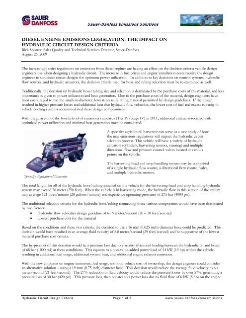
Specialty Agricultural Harvester<br />
A specialty agricultural harvester can serve as a case study of how<br />
the new emissions regulations will impact the hydraulic circuit<br />
selection process. This vehicle will have a variety of hydraulic<br />
actuators (cylinders, harvesting motors, steering) and multiple<br />
directional flow and pressure control valves located at various<br />
points on the vehicle.<br />
The harvesting head and crop handling system may be comprised<br />
of a single hydraulic flow source, a directional flow control valve,<br />
and multiple hydraulic motors.<br />
The total length for all of the hydraulic hose/tubing installed on the vehicle for the harvesting head and crop handling hydraulic<br />
system may exceed 76 meter (250 feet). When the vehicle is in harvesting mode, the hydraulic flow in this section of the system<br />
may average 121 litres/minute (28 gallons/minute) and experience operating pressures of 275 bar (4000 psi).<br />
The traditional selection criteria for the hydraulic hose/tubing connecting these various components would have been dominated<br />
by two factors:<br />
• Hydraulic flow velocities design guideline of 6 - 9 meter/second (20 – 30 feet/second)<br />
• Lowest purchase cost for the material<br />
Based on the conditions and these two criteria, the decision to use a 16 mm (0.625 inch) diameter hose could be predicted. This<br />
decision would have resulted in an average fluid velocity of 8.8 meter/second (29 feet/second) and be supportive of the lowest<br />
material purchase cost criteria.<br />
The by-product of this decision would be a pressure loss due to viscosity (frictional loading between the hydraulic oil and hose)<br />
of 68 bar (1000 psi) at these conditions. This equates to a non-value-added power load of 14 kW (19 hp) within the vehicle,<br />
resulting in additional fuel usage, additional system heat, and additional engine exhaust emissions.<br />
With the new emphasis on engine emissions, fuel usage, and total vehicle cost of ownership, the design engineer could consider<br />
an alternative solution – using a 19 mm (0.75 inch) diameter hose. This decision would reduce the average fluid velocity to 6.4<br />
meter/second (21 feet/second). The 27% reduction in fluid velocity would reduce the pressure losses by over 57%, generating a<br />
pressure loss of 30 bar (420 psi). This pressure loss, then equates to a power loss due to fluid flow of 6 kW (8 hp) on the engine.<br />
Hydraulic Circuit Design Criteria Page 1 of 2 www.sauer-danfoss.com/emissions
<strong>Sauer</strong>-<strong>Danfoss</strong> Emissions Solutions<br />
While the initial purchase cost increases (76 Euro, in the example below), this cost is more than offset by the reduction in annual<br />
fuel usage (1200 Euro in the example):<br />
Installed cost increases by<br />
76 Euro<br />
Annual fuel cost decreases<br />
by over 1200 Euro<br />
Perhaps most importantly, the design engineer now has an additional solution to offset the challenges (increased heat load,<br />
reduced power available) presented with Tier IV/Stage IV compliant diesel engines.<br />
<strong>Sauer</strong>-<strong>Danfoss</strong> has developed a hydraulic circuit cost analysis tool to assist the design engineer in addressing these new criteria.<br />
This tool provides the vehicle design engineer the ability to consider variables like:<br />
• machine usage<br />
• fuel costs<br />
• hydraulic circuit line lengths<br />
• hydraulic circuit conduit diameters<br />
• flow rates<br />
• oil viscosities<br />
All of these considerations can be taken together to achieve an effective balance between cost, efficiency, and total cost of<br />
ownership.<br />
Contact your <strong>Sauer</strong>-<strong>Danfoss</strong> representative for more information on this tool and a demonstration on the many ways it can be<br />
used to help solve your design challenges.<br />
Hydraulic Circuit Design Criteria Page 2 of 2 www.sauer-danfoss.com/emissions