INT'L Shortcut Cartridge Catalogue - Bibus SK, s.r.o.
INT'L Shortcut Cartridge Catalogue - Bibus SK, s.r.o.
INT'L Shortcut Cartridge Catalogue - Bibus SK, s.r.o.

You also want an ePaper? Increase the reach of your titles
YUMPU automatically turns print PDFs into web optimized ePapers that Google loves.
Over 35 New Products in this <strong>Catalogue</strong><br />
Relief <strong>Cartridge</strong> Valves<br />
Page 7: The RDDA-3** (series 1) and RDFA-3** (series 2) are<br />
non-adjustable direct-acting relief cartridges. They are<br />
normally closed, pressure-limiting valves used to protect<br />
hydraulic components from pressure transients. When the<br />
pressure at the inlet (port 1) reaches the valve setting, the<br />
valve starts to open to tank (port 2), throttling the flow to<br />
limit the pressure rise. These valves are smooth and quiet,<br />
with essentially zero leakage, dirt tolerant, immune to<br />
silting, and are very fast.<br />
Page 8: The RDDT-Q** (series 1) and RDFT-Q** (series 2)<br />
are direct-acting relief cartridges. They are normally<br />
closed, pressure-limiting valves used to protect hydraulic<br />
components from pressure transients. When the pressure<br />
at the inlet (port 1) reaches the valve setting, the valve<br />
starts to open to tank (port 2), throttling the flow to limit<br />
the pressure rise. These valves are smooth and quiet, with<br />
essentially zero leakage, dirt tolerant, immune to silting,<br />
and are very fast. These CE marked valves are safety<br />
valves that meet the requirements of the European<br />
Directive for Pressurized Devices (PED) 97/23/EC.<br />
Page 12: RP*S are pilot-operated, balanced-poppet relief<br />
cartridges and are normally closed pressure regulating<br />
valves. When the pressure at the inlet (port 1) reaches the<br />
valve setting, the valve starts to open to tank (port 2),<br />
throttling flow to regulate the pressure. These valves are<br />
accurate, smooth, quiet, fast, and have low pressure rise<br />
vs. flow.<br />
Page 11: The RPET, RPGT, RPIT, and RPKT are series 1, 2,<br />
3, and 4 pilot operated soft relief valves which control the<br />
rate of pressure rise in a system as well as maximum<br />
pressure. These valves provide excellent pressure<br />
protection and reduced system shock.<br />
Page 12: The RQCB is a series 0 kick-down, relief valve which<br />
works like a circuit breaker in an electrical system. When<br />
the pressure setting is reached, the valve kicks wide open,<br />
passing flow at low pressure. It stays open until flow to<br />
the valve stops.<br />
Page 15: The RBAN-X** is an electro-proportional, direct<br />
acting pilot relief valve which fits into the Sun T-8A<br />
cavity. This valve has an inverse operation, meaning the<br />
valve is at a maximum setting with no signal to the<br />
solenoid coil. The setting decreases as the signal<br />
increases.<br />
Page 17: The RP*S-8** are seated-style, normally closed<br />
modulating valves with a T-8A cavity. When used with<br />
RBAP proportional relief fitted into this cavity, the RPES<br />
becomes a series 1 proportional relief with low main stage<br />
leakage.<br />
Page 19: RV*S-*** are vented, pilot operated, relief valves<br />
with a seated style main stage. When compared to a<br />
standard spool-type vented relief, this valve provides<br />
lower leakage, and faster response resulting in reduced<br />
overshoot and improved pressure control.<br />
Int’l <strong>Shortcut</strong> <strong>Catalogue</strong> #999-901-312 1<br />
Page 20: The RV*T is a vented, pilot operated, soft relief valve<br />
which controls the rate of pressure rise in a system as well<br />
as the maximum pressure. By providing a smoother,<br />
controlled pressure loading in the non-vented condition,<br />
this valve minimizes shock in systems.<br />
Sequence <strong>Cartridge</strong> Valves<br />
Page 28: The SQBB is a series 0 kick-down sequence valve<br />
used to sequence a function in a system when pressure on<br />
the inlet reaches the valve setting. The valve goes wide<br />
open and stays open until flow to the valve stops.<br />
Reducing/Relieving <strong>Cartridge</strong> Valves<br />
Page 42: The PS*T-*** is a direct acting, pressure reducing/<br />
relieving valve mainstage piloted from port 4. This valve<br />
incorporates a damped construction for stable operation<br />
allowing the use of high reduced pressure.<br />
Counterbalance <strong>Cartridge</strong> Valves<br />
Sun has added a number of fixed setting valves to its<br />
counterbalance line of products: CBB*-X**, (Semirestrictive,<br />
40 L/min.), CBA*-X (Restrictive, 10 L/min.),<br />
CBB*-X (Restrictive, 20 L/min.) and CBC*-X (Standard,<br />
60 L/min.). Fixed-setting, 3-port, T-11A cavity,<br />
counterbalance valves with pilot assist function similar to<br />
the adjustable versions except the fixed setting is pre-set<br />
to a nominal value. These fixed-setting valves are meant<br />
to control an overrunning load. The check valve allows<br />
free flow from the directional valve (port 2) to the load<br />
(port 1), while a direct-acting, pilot-assisted relief valve<br />
controls flow from port 1 to port 2. Pilot assist at port 3<br />
lowers the effective setting of the relief valve at a rate<br />
determined by the pilot ratio. See page 72. Also review<br />
these products at www.sunhydraulics.com. Products:<br />
Counterbalance: Click View All Counterbalance Valves.<br />
Load Control: Load Reactive <strong>Cartridge</strong> Valves<br />
Page 64: MB*A-L** (3:1 pilot ratio), MB*B-L** (1.5:1 pilot<br />
ratio), MB*G-L** (4.5:1 pilot ratio) are load reactive,<br />
non-vented load control valves. This valve is functionally<br />
a 3 port counterbalance valve. It seats as a poppet valve<br />
and modulates as a spool valve.<br />
Page 65: MB*A-X** (3:1 pilot ratio), MB*B-X** (1.5:1 pilot<br />
ratio), MB*G-X** (4.5:1 pilot ratio) are load reactive,<br />
non-vented, fixed setting, load control valves. This valve<br />
is functionally a 3 port counterbalance valve. It seats as a<br />
poppet valve and modulates as a spool valve.<br />
Page 66: MW*A-L** (3:1 pilot ratio), MW*B-L** (1.5:1<br />
pilot ratio), MW*G-L** (4.5:1 pilot ratio) are load<br />
reactive, vented, load control valves. This valve is<br />
functionally a 4 port counterbalance valve. It seats as a<br />
poppet valve and modulates as a spool valve.
Over 35 New Products in this <strong>Catalogue</strong><br />
Load Control: Load Reactive <strong>Cartridge</strong> Valves<br />
(Continued)<br />
Page 67: MW*A-X** (3:1 pilot ratio), MW*B-X** (1.5:1<br />
pilot ratio), MW*G-X** (4.5:1 pilot ratio) are load<br />
reactive, vented, load control valves. This valve is<br />
functionally a 4 port counterbalance valve. It seats as a<br />
poppet valve and modulates as a spool valve.<br />
Load Control: Balanced <strong>Cartridge</strong> Valves<br />
Page 70: The MB*M-X** is a balanced, non-vented, nonrelieving<br />
load control valve. This valve displays<br />
characteristics of a pressure compensating flow control<br />
valve. Performance is best in the meter-out mode with<br />
port 1 being the load and port 2 being tank.<br />
Page 71: The MW*M-X** is a vented, balanced non-relieving,<br />
load control valves that combines a balanced modulating<br />
element with a reverse flow check. This valve displays<br />
characteristics of a pressure compensating flow control<br />
valve. Performance is best in the meter-out mode with<br />
port 1 being the load and port 2 being tank.<br />
Check <strong>Cartridge</strong> Valves<br />
Page 74: CXAA-XB* is a free flow, nose-to-side, check valve<br />
which fits into T-8A cavity.<br />
Logic Element <strong>Cartridge</strong> Valves<br />
Page 110: LO*C-ZD* is a balanced poppet, pilot-to-close,<br />
spring biased closed, logic element with position<br />
indicating switch.<br />
Page 111: LO*O-ZD* is a balanced poppet, pilot-to-close,<br />
spring biased open, logic element with position indicating<br />
switch.<br />
Page 116: The LH*A-X** is a bypass/restrictive, priority<br />
modulating element.<br />
Solenoid Operated <strong>Cartridge</strong> Valves<br />
Page 132: The DTDA-S** is a 2-position, 2-way direct<br />
operating poppet-type directional solenoid valve with soft<br />
shift armature.<br />
Page 133: The DAAL-S** is a 2-position, 2-way, spool-type<br />
pilot solenoid valve with soft shift armature.<br />
Page 134: The DLDA-S** is a 2-position, 2-way spool-type<br />
directional solenoid valve with soft shift armature.<br />
Page 135: The DWDA-X** is a 2-position, 3-way poppet-type<br />
directional solenoid valve.<br />
Page 136: The DBAL-S** is a 2-position, 3-way, spool-type<br />
pilot solenoid valve with soft shift armature.<br />
Page 137: The DMDA-S** is a 2-position, 3-way spool-type<br />
directional solenoid valve with soft shift armature.<br />
Page 138: The DNDA-S** is a 2-position, 4-way spool-type<br />
directional solenoid valve with soft shift armature.<br />
Page 139: The DNDC-X** is a direct acting, solenoid-operated,<br />
4-way, 3-position spool valve that is spring centred to the<br />
neutral position.<br />
Pilot Control <strong>Cartridge</strong> Valves<br />
Page 146: DAAL-X** is a 2-way, solenoid operated,<br />
directional spool-type, pilot valve.<br />
Page 146: DAAL-S** is a 2-position, 2-way, spool-type pilot<br />
solenoid valve with soft shift armature.<br />
Page 150: The DBAL-X** is a 3-way, 2-position, solenoid<br />
operated, directional spool-type, pilot valve.<br />
Page 150: DBAL-S** is a 3-way, 2-position, solenoid operated,<br />
directional spool-type pilot valve with soft shift armature.<br />
Corrosion Resistant <strong>Cartridge</strong> Valves<br />
Sun is continually adding to its line of corrosion resistant<br />
valves. These valve have stainless steel and titanium<br />
external components with heat treated internal<br />
components in carbon and alloy steels. These valves are<br />
recommended for marine, oil and gas industries and for<br />
use in stationary aero-drives. All external components are<br />
qualified by a 1,000 hour salt spray test to ASTM B117-<br />
03. In all cases, the internal working components remain<br />
the same as the standard Sun valve. Where the cartridge<br />
product is offered in corrosion resistant materials, you<br />
will see a note in the bottom right corner of the page. Visit<br />
www.sunhydraulics.com for complete information on<br />
our Corrosion Resistant <strong>Cartridge</strong>s. Products:<br />
<strong>Cartridge</strong>s: Corrosion Resistant: View All Corrosion<br />
Resistant <strong>Cartridge</strong>s for complete information about<br />
these cartridges.<br />
Weatherized Coils and Weatherized Coil Kits<br />
Page 190, 191: Sun’s new weatherized coils and kits are<br />
designed for Sun’s full flow solenoid operated and<br />
electro-proportional cartridge valves. They are protection<br />
against high-pressure wash-downs or marine<br />
environments for Sun’s electrically-actuated cartridge<br />
valves. These coil kits are only available with the<br />
Metri-Pack Series 150-2M connector with a choice of<br />
four voltages.<br />
A weatherization kit is required in conjunction with a<br />
weatherized coil and a modified cavity (consult the Sun<br />
website to view cavity modification instructions for the<br />
use of each kit). The coil is not included in the kits and<br />
must be purchased separately. Weatherization kits are<br />
cartridge model code and cavity dependant. These kits<br />
are intended for new installations only and are not<br />
suitable for retrofitting existing equipment or for<br />
standard Sun bodies.<br />
Consult www.sunhydraulics.com for complete details on<br />
weatherized coils and weatherized coil kits. Go to<br />
Products: <strong>Cartridge</strong>s: Coils: View All Coils: Weatherized<br />
Coils. View individual Weatherized Coil Seal Kit page for<br />
detailed installation instructions.<br />
2 Int’l <strong>Shortcut</strong> <strong>Catalogue</strong> #999-901-312
Contents<br />
Model Codes printed in Red are Preferred Versions of Products shown in this catalogue and most readily available.<br />
Relief <strong>Cartridge</strong> Valves . . . . . . . . . . . . . . . . . . . . . . . . . . . . . . . . 5<br />
Sequence <strong>Cartridge</strong> Valves . . . . . . . . . . . . . . . . . . . . . . . . . . . . 25<br />
Reducing and Reducing/Relieving. . . . . . . . . . . . . . . . . . . . .<br />
<strong>Cartridge</strong> Valves<br />
33<br />
Pilot-to-Open Check <strong>Cartridge</strong> Valves . . . . . . . . . . . . . . . . . 47<br />
Counterbalance <strong>Cartridge</strong> Valves. . . . . . . . . . . . . . . . . . . . . . 51<br />
Load Control: Reactive <strong>Cartridge</strong> Valves . . . . . . . . . . . . . . 63<br />
Load Control: Balanced <strong>Cartridge</strong> Valves . . . . . . . . . . . . . 69<br />
Check <strong>Cartridge</strong> Valves . . . . . . . . . . . . . . . . . . . . . . . . . . . . . . . . 73<br />
Flow Control <strong>Cartridge</strong> Valves . . . . . . . . . . . . . . . . . . . . . . . . . 79<br />
Flow Divider / Combiner <strong>Cartridge</strong> Valves . . . . . . . . . . . . . 93<br />
Logic Elements . . . . . . . . . . . . . . . . . . . . . . . . . . . . . . . . . . . . . . . . 99<br />
Directional <strong>Cartridge</strong> Valves . . . . . . . . . . . . . . . . . . . . . . . . . . . 117<br />
Solenoid Operated <strong>Cartridge</strong> Valves. . . . . . . . . . . . . . . . . . . 131<br />
Pilot Control <strong>Cartridge</strong> Valves . . . . . . . . . . . . . . . . . . . . . . . . . 141<br />
Int’l <strong>Shortcut</strong> <strong>Catalogue</strong> #999-901-312 3<br />
Shuttle <strong>Cartridge</strong> Valves. . . . . . . . . . . . . . . . . . . . . . . . . . . . . . . 155<br />
Circuit Savers. . . . . . . . . . . . . . . . . . . . . . . . . . . . . . . . . . . . . . . . . . 163<br />
Hybrid Relief <strong>Cartridge</strong> Valves . . . . . . . . . . . . . . . . . . . . . . . . 171<br />
General Information . . . . . . . . . . . . . . . . . . . . . . . . . . . . . . . . . . . 177<br />
<strong>Cartridge</strong> Control Options . . . . . . . . . . . . . . . . . . . . . . . . . . . . . . . . . 178<br />
<strong>Cartridge</strong> Control Kits . . . . . . . . . . . . . . . . . . . . . . . . . . . . . . . . . . . . 179<br />
Cavity Plugs . . . . . . . . . . . . . . . . . . . . . . . . . . . . . . . . . . . . . . . . . . . . 183<br />
Sun Coil Options for Solenoids (Metal Housing, Round) . . . . . . . . . 187<br />
Sun Coil Options with Embedded Electronic. . . . . . . . . . . . . . . . . . . 188<br />
Proportional Amplifiers<br />
Sun Weatherized Coils and Coil Kits . . . . . . . . . . . . . . . . . . . . . . . . . 190<br />
Sun Coil 790-***** Part Numbering System . . . . . . . . . . . . . . . . . . 191<br />
Orifice Pressure Drop Data. . . . . . . . . . . . . . . . . . . . . . . . . . . . . . . . . 192<br />
Sun Model Code System . . . . . . . . . . . . . . . . . . . . . . . . . . . . . . 193<br />
Sun Model Code Index. . . . . . . . . . . . . . . . . . . . . . . . . . . . . . . . . 194<br />
Warranty . . . . . . . . . . . . . . . . . . . . . . . . . . . . . . . . . . . . . . . . . . . . . . . 199<br />
International Distribution . . . . . . . . . . . . . . . . . . . . . . . . . . . . . . 200
Specifications, descriptions and illustrative material contained herein were accurate as known at the<br />
time this publication was approved for printing.<br />
Sun Hydraulics reserves the right to discontinue models at any time, or change prices, specifications<br />
or designs without notice or incurring obligation.<br />
All rights reserved. This book, or any part thereof, may not be reproduced or transmitted in any form<br />
or by any means, electronic or mechanical, including photocopying, recording,<br />
or information storage and retrieval systems, for any purpose<br />
without the express written permission of Sun Hydraulics Corporation,<br />
1500 West University Parkway, Sarasota, Florida, 34243, USA.<br />
Copyright © 2009 Sun Hydraulics Corporation<br />
Sarasota, FL 34243 USA<br />
Printed in the United States of America<br />
4 Int’l <strong>Shortcut</strong> <strong>Catalogue</strong> #999-901-312
2 1<br />
2<br />
2<br />
2<br />
1<br />
1<br />
1<br />
2 1<br />
2 1<br />
2 1<br />
2<br />
Air Pilot<br />
1<br />
2 1<br />
2 1<br />
2<br />
2<br />
T-8A<br />
Cav<br />
T-8A<br />
Cav<br />
1<br />
1<br />
3<br />
2 1<br />
3<br />
2 1<br />
3<br />
2 1<br />
2<br />
4<br />
3<br />
2 1<br />
3<br />
4 T-8A<br />
Cav<br />
2<br />
3<br />
1<br />
1<br />
Int’l <strong>Shortcut</strong> <strong>Catalogue</strong> #999-901-312 5<br />
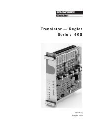
Relief <strong>Cartridge</strong> Valves<br />
<strong>Cartridge</strong> Type Page<br />
Pilot Operated, Balanced Piston 6<br />
Direct Acting and Direct Acting, Non-Adjustable 7<br />
Direct Acting, CE Marked 8<br />
Direct Acting, Pilot Capacity 9<br />
Pilot Operated, Balanced Poppet 10<br />
Pilot Operated, Balanced Poppet, Soft 11<br />
Pilot Operated, Kick-down, Balanced Piston 12<br />
Pilot Operated, Balanced Piston, Air Controlled 13<br />
Electro-Proportional, Pilot Capacity 14<br />
Electro-Proportional, Pilot Capacity, High Pressure Setting<br />
with No Command, Inverse Function<br />
Pilot Operated, Balanced Piston, Main Stage<br />
with Integral T-8A Control Cavity<br />
Pilot Operated, Balanced Poppet, Main Stage<br />
with Integral T-8A Control Cavity<br />
Pilot Operated, Balanced Piston, Ventable 18<br />
Pilot Operated, Balanced Poppet, Ventable 19<br />
Pilot Operated, Balanced Poppet, Ventable, Soft 20<br />
Bypass Compensator with Relief Function,<br />
Normally Closed<br />
Pilot Operated, Balanced Piston, Ventable<br />
with External Drain<br />
Electro-Proportional, Pilot Operated,<br />
Balanced Piston, Ventable, Drain to Port 4,<br />
Main Stage with Integral T-8A Control Cavity<br />
15<br />
16<br />
17<br />
21<br />
22<br />
23
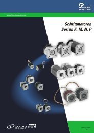
Relief Valves<br />
PILOT OPERATED, BALANCED PISTON<br />
Full Adjustment 5 Turns<br />
+ -<br />
b<br />
2<br />
Outlet<br />
Inlet<br />
1<br />
Performance Curves<br />
c<br />
a<br />
Locating<br />
Shoulder<br />
2 1<br />
<strong>Cartridge</strong> Dimensions<br />
Capacity<br />
Typical<br />
<strong>Cartridge</strong><br />
Model Code<br />
Cavity a b<br />
L<br />
c<br />
C K<br />
Installation<br />
Torque<br />
(Nm)<br />
45 L/min. RPCC – LAN T - 162A 31,0 19,1 53,6 55,1 60,7 35 - 40<br />
95 L/min. RPEC – LAN T - 10A 39,6 22,2 50,8 54,6 57,2 45 - 50<br />
200 L/min. RPGC – LAN T-3A 47,8 28,6 53,8 55,4 60,5 60 - 70<br />
380 L/min. RPIC – LAN T - 16A 62,0 31,8 62,0 62,7 68,3 200 - 215<br />
760 L/min. RPKC – LAN T-18A 79,5 41,3 71,4 74,7 77,7 465 - 500<br />
RPCC RPEC RPGC RPIC RPKC<br />
Typical Pressure Rise<br />
P = bar<br />
350<br />
300<br />
250<br />
200<br />
150<br />
100<br />
50<br />
P = bar<br />
350<br />
300<br />
250<br />
200<br />
150<br />
100<br />
50<br />
P = bar<br />
350<br />
300<br />
250<br />
200<br />
150<br />
100<br />
50<br />
0 25 50 75<br />
Flow = L/min.<br />
100<br />
0 50 100 150<br />
Flow = L/min.<br />
200<br />
0 100 200 300<br />
Flow = L/min.<br />
400<br />
0 200 400 600<br />
Flow = L/min.<br />
800<br />
0 400 800 1200<br />
Flow = L/min.<br />
■<br />
■<br />
Maximum operating pressure = 350 bar.<br />
Maximum valve leakage at 24 cSt = RPCC, RPEC: 30 cc/min. at 70 bar; RPGC: 50 cc/min. at 70 bar;<br />
RPIC: 65,5 cc/min. at 70 bar; RPKC: 80 cc/min. at 70 bar.<br />
■ Typical response time 10 ms.<br />
■ Factory pressure settings established at 15 L/min.<br />
■ Will accept maximum pressure at Port 2.<br />
■ Back pressure on the tank port (port 2) is directly additive at a 1:1 ratio to the valve setting.<br />
OPTION ORDERING INFORMATION<br />
RP ✱ C – ✱ ✱ ✱<br />
Nominal<br />
Capacity<br />
Control** Adjustment Range Seal Material<br />
C 45 L/min. L Standard Screw RPCC only: N Buna-N<br />
Adjustment A 5 - 210 bar<br />
E 95 L/min. Standard set at 70 bar V Viton<br />
C* Tamper Resistant B 5 - 105 bar<br />
G 200 L/min. Factory Set Standard set at 70 bar<br />
C 5 - 420 bar<br />
I 380 L/min. K Handknob Standard set at 70 bar<br />
with Lock Knob N 5 - 55 bar<br />
K 760 L/min. Standard set at 30 bar<br />
RPEC, Q 5 - 25 bar<br />
RPGC only: Standard set at 14 bar<br />
O Handknob with W 5 - 315 bar<br />
Panel Mount Standard set at 70 bar<br />
* Special setting required. RPEC, RPGC,<br />
Specify at time of order. RPIC, RPKC only:<br />
A 7 - 210 bar<br />
Standard set at 70 bar<br />
B 3,5 - 105 bar<br />
Standard set at 70 bar<br />
C 10,5 - 420 bar<br />
** See page 178 Standard set at 70 bar<br />
for information N 4 - 55 bar<br />
on Control Options Standard set at 28 bar<br />
Q 4 - 25 bar<br />
Customer specified Standard set at 14 bar<br />
special setting W 10,5 - 315 bar<br />
stamped on hex. Standard set at 70 bar<br />
Visit www.sunhydraulics.com for current list pricing and complete technical information on all Sun products.<br />
P = bar<br />
350<br />
300<br />
250<br />
200<br />
150<br />
100<br />
50<br />
6 Int’l <strong>Shortcut</strong> <strong>Catalogue</strong> #999-901-312<br />
P = bar<br />
350<br />
300<br />
250<br />
200<br />
150<br />
100<br />
50<br />
Consult the Sun website for<br />
our most recent and complete<br />
information on the full Corrosion<br />
Resistant line of products.<br />
1600
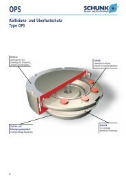
Relief Valves<br />
DIRECT ACTING AND DIRECT ACTING, NON-ADJUSTABLE<br />
Full Adjustment 5 Turns<br />
+ -<br />
L Control<br />
P = bar<br />
3 Control<br />
b<br />
2<br />
Outlet<br />
RDBA RDDA RDFA RDHA RDJA<br />
350<br />
300<br />
250<br />
200<br />
150<br />
100<br />
50<br />
Inlet<br />
1<br />
c<br />
a<br />
Performance Curves<br />
Locating<br />
Shoulder<br />
P = bar<br />
350<br />
300<br />
250<br />
200<br />
150<br />
100<br />
50<br />
Visit www.sunhydraulics.com for current list pricing and complete technical information on all Sun products.<br />
Int’l <strong>Shortcut</strong> <strong>Catalogue</strong> #999-901-312 7<br />
2<br />
RD*A<br />
1<br />
<strong>Cartridge</strong> Dimensions<br />
Capacity<br />
Typical<br />
<strong>Cartridge</strong><br />
Model Code<br />
Cavity a b<br />
L<br />
c<br />
C<br />
Installation<br />
Torque<br />
(Nm)<br />
45 L/min. RDBA – LAN T - 162A 31,0 19,1 53,6 56,4 35 - 40<br />
95 L/min. RDDA – LAN T - 10A 39,6 22,2 59,2 63,2 45 - 50<br />
200 L/min. RDFA – LAN T-3A 47,8 28,6 63,5 65,0 60 - 70<br />
380 L/min. RDHA – LAN T - 16A 62,0 31,8 82,6 84,1 200 - 215<br />
760 L/min. RDJA – LAN T - 18A 79,5 41,3 100,0 103,4 465 - 500<br />
P = bar<br />
Typical Pressure Rise<br />
350<br />
300<br />
250<br />
200<br />
150<br />
100<br />
50<br />
0 10 20 30 40 50<br />
0 25 50 75 100<br />
0 50 100 150 200<br />
0 100 200 300 400<br />
0 200 400 600 800<br />
Flow = L/min.<br />
Flow = L/min.<br />
Flow = L/min.<br />
Flow = L/min.<br />
Flow = L/min.<br />
■ Maximum operating pressure = 350 bar.<br />
■ Maximum valve leakage at reseat = 0,7 cc/min.<br />
■ Typical response time 2 ms.<br />
■ Factory pressure settings established at 15 L/min.<br />
■ Will accept maximum pressure at Port 2.<br />
■ Back pressure on the tank port (port 2) is directly additive at a 1:1 ratio to the valve setting.<br />
■ The seals on the adjust screw are exposed to system pressure which means this valve can only be adjusted when<br />
the pressure is removed. The setting procedure is; check the setting, remove the pressure, adjust the valve, check the new setting.<br />
■ Reseat exceeds 90% of cracking pressure.<br />
■ Select a spring range where the desired relief setting is approximately mid-range between the minimum and maximum pressure<br />
to ensure maximum valve repeatability.<br />
OPTION ORDERING INFORMATION<br />
P = bar<br />
350<br />
300<br />
250<br />
200<br />
150<br />
100<br />
50<br />
RD ✱ A – ✱ ✱ ✱<br />
Nominal<br />
Capacity<br />
Control** Adjustment Range Seal Material<br />
B 45 L/min. L Standard Screw A 35 - 210 bar N Buna-N<br />
Adjustment Standard set at 70 bar<br />
D 95 L/min. B 20 - 105 bar V Viton<br />
C*Tamper Resistant Standard set at 70 bar<br />
F 200 L/min. Factory Set C 70 - 420 bar<br />
Standard set at 70 bar<br />
H 380 L/min. RDDA, RDFA only: D 14 - 55 bar<br />
3* Non-Adjustable Standard set at 28 bar<br />
J 760 L/min. E 10 - 28 bar<br />
* Special setting required. Standard set at 14 bar<br />
Specify at time of order.<br />
** See page 178<br />
S 3,5 - 14 bar<br />
Standard set at 7 bar<br />
W 55 - 315 bar<br />
Standard set at 70 bar<br />
U.S. Patent #4,742,846<br />
European Patent Pending<br />
for information<br />
on Control Options<br />
Customer specified<br />
special setting<br />
stamped on hex.<br />
RDDA-3, RDFA-3<br />
only available with<br />
A, C, D ranges.<br />
Consult the Sun website<br />
for our most recent and<br />
complete information<br />
on the full Corrosion<br />
Resistant line of products.<br />
P = bar<br />
350<br />
300<br />
250<br />
200<br />
150<br />
100<br />
50
Relief Valves<br />
DIRECT ACTING, CE MARKED<br />
b<br />
Full Adjustment 5 Turns<br />
+ -<br />
2<br />
Outlet<br />
1<br />
Inlet<br />
Performance Curves<br />
c<br />
a<br />
Locating<br />
Shoulder<br />
Nominal<br />
Capacity<br />
RDDT RDFT<br />
Permissible Operating Range<br />
■ Maximum valve leakage at reseat = 0,7 cc/min.<br />
■ Reseat = > 90% of set pressure.<br />
■ Typical response time 2 ms.<br />
■ Standard settings for preset valves: 100, 140, 160, 210, 250, and 330 bar.<br />
■ Pressure setting from 100 bar up to 422 bar are approved and certified by TüV.<br />
■ Will accept maximum pressure at port 2; suitable for use in cross-port relief circuits.<br />
■ Back pressure on the tank port (port 2) is additive to the valve setting at a 1:1 ratio.<br />
RD ✱ T – ✱ ✱ ✱<br />
Control Adjustment Range Seal Material<br />
D 75 L/min. Q*Capped and RDDT: N Buna-N<br />
Lockwire A 100 - 210 bar<br />
V Viton<br />
F 79 L/min. * Special setting required.<br />
Specify at time of order.<br />
C 315 - 422 bar<br />
W 211 - 314 bar<br />
U.S. Patent #4,742,846<br />
2<br />
Capacity<br />
75 L/min.<br />
79 L/min.<br />
OPTION ORDERING INFORMATION<br />
1<br />
Typical<br />
<strong>Cartridge</strong><br />
Model Code<br />
The CE marked valve is a safety valve that meets the requirements of the European<br />
Directive for Pressurized Devices (PED) 97/23/EC.<br />
Each delivery contains a TüV approval, which is a certification of the excess<br />
operating pressure and the approved flow, an EC declaration of conformity, and an<br />
instructional manual. See Sun website for further information.<br />
RDFT:<br />
A 106 - 209 bar<br />
B 60 - 105 bar<br />
C 210 - 420 bar<br />
<strong>Cartridge</strong> Dimensions<br />
Cavity a b c<br />
Visit www.sunhydraulics.com for current list pricing and complete technical information on all Sun products.<br />
Installation<br />
Torque<br />
(Nm)<br />
RDDT – QAN T-10A 40,0 mm 22,2 mm 65,0 mm 45 - 50<br />
RDFT – QAN T - 3A 47,8 mm 28,6 mm 70,4 mm 60 - 70<br />
450<br />
450<br />
400<br />
350<br />
300<br />
250<br />
200<br />
150<br />
Permissible<br />
Range *<br />
400<br />
350<br />
300<br />
250<br />
200<br />
150<br />
100<br />
Permissible<br />
Range<br />
100<br />
0 20 40 60 80<br />
50<br />
0 20 40 60 80 100<br />
Flow = L/min.<br />
Flow = L/min.<br />
Maximum Approved Flow<br />
*Approved flow at 210 bar is 75 L/min.<br />
Maximum Approved Flow<br />
P = bar<br />
P = bar<br />
8 Int’l <strong>Shortcut</strong> <strong>Catalogue</strong> #999-901-312
Relief Valves<br />
DIRECT ACTING, PILOT CAPACITY<br />
Full Adjustment 5 Turns<br />
+ -<br />
b<br />
2<br />
Outlet<br />
Inlet<br />
Performance Curves<br />
1<br />
c<br />
a<br />
Locating<br />
Shoulder<br />
RBAC RBAA RBAE<br />
P = bar<br />
350<br />
300<br />
250<br />
200<br />
150<br />
100<br />
50<br />
Visit www.sunhydraulics.com for current list pricing and complete technical information on all Sun products.<br />
Int’l <strong>Shortcut</strong> <strong>Catalogue</strong> #999-901-312 9<br />
2<br />
1<br />
<strong>Cartridge</strong> Dimensions<br />
Capacity<br />
Typical<br />
<strong>Cartridge</strong><br />
Model Code<br />
Cavity a b<br />
L C<br />
c<br />
K O<br />
Installation<br />
Torque<br />
(Nm)<br />
1 L/min. RBAC – LAN T - 10A 39,6 22,2 50,8 54,6 57,2 58,0 45 - 50<br />
2 L/min. RBAA – LAN T - 3A 47,8 28,6 53,8 55,4 60,5 61,0 60 - 70<br />
10 L/min. RBAE – LAN T-8A 19,0 22,2 60,5 62,7 67,6 67,6 35 - 40<br />
0 0,32 0,64 0,96 1,28 1,6<br />
Flow = L/min.<br />
Typical Pressure Rise<br />
■ Maximum operating pressure = 350 bar.<br />
■ Maximum valve leakage at reseat at 24 cSt = RBAC, RBAA: 0,4 cc/min.; RBAE: 1 cc/min.<br />
■ Typical response time 2 ms.<br />
■ Back pressure on the tank port (port 2) is directly additive to the pressure setting<br />
at port 1 (inlet) at a 1:1 ratio to the valve setting.<br />
■ RBAE: Utilizes the Sun T-8A, 2 port cavity making it the ideal choice to use in conjunction with Sun’s<br />
main stage pilot or vent-to-operate cartridges. Separate pilot lines are eliminated and only one cavity<br />
needs to be machined to accommodate both the control and primary function. Note: All 2-position,<br />
2-way pilot stage control cartridges utilize the same cavity and are physically interchangeable.<br />
Functionality is the only consideration.<br />
OPTION ORDERING INFORMATION<br />
RB A ✱ – ✱ ✱ ✱<br />
Nominal<br />
Capacity<br />
Control** Adjustment Range Seal Material<br />
AC 1 L/min. L Standard Screw A 1,7 - 210 bar N Buna-N<br />
Adjustment Standard set at 70 bar<br />
V Viton<br />
AA 2 L/min. C*Tamper Resistant B 1,7 - 105 bar<br />
with Lock Knob Standard set at 70 bar<br />
AE 10 L/min. K Handknob C 1,7 - 420 bar<br />
Factory Set Standard set at 70 bar<br />
P = bar<br />
O Handknob with D 1,7 - 55 bar<br />
Panel Mount Standard set at 25 bar<br />
* Special setting required. E 1,7 - 25 bar<br />
Specify at time of order. Standard set at 14 bar<br />
** See page 178 W 1,7 - 315 bar<br />
for information Standard set at 70 bar<br />
on Control Options<br />
Customer specified special<br />
setting stamped on hex.<br />
350<br />
300<br />
250<br />
200<br />
150<br />
100<br />
50<br />
0 0,5 1,0 1,5 2,0 2,5<br />
Flow = L/min.<br />
P = bar<br />
400<br />
300<br />
200<br />
100<br />
0 2 4 6 8 10<br />
Flow = L/min.<br />
Consult the Sun website for<br />
our most recent and complete<br />
information on the full Corrosion<br />
Resistant line of products.
Relief Valves<br />
PILOT OPERATED, BALANCED POPPET<br />
Full Adjustment 5 Turns<br />
+ -<br />
b<br />
2<br />
Outlet<br />
Inlet 1<br />
Performance Curves<br />
P = bar<br />
2 1<br />
<strong>Cartridge</strong> Dimensions<br />
Capacity<br />
Typical<br />
<strong>Cartridge</strong><br />
Model Code<br />
Cavity a b<br />
L<br />
c<br />
C K<br />
Installation<br />
Torque<br />
(Nm)<br />
95 L/min. RPES – LAN T-10A 39,6 22,2 50,8 54,6 57,2 40 - 50<br />
200 L/min. RPGS – LAN T - 3A 47,8 28,6 53,8 55,4 60,5 60 - 70<br />
380 L/min. RPIS – LAN T-16A 62,0 31,8 62,0 62,7 68,3 200 - 215<br />
760 L/min. RPKS – LAN T - 18A 79,5 41,3 71,4 74,7 77,7 465 - 500<br />
RPES RPGS RPIS RPKS<br />
250<br />
200<br />
150<br />
100<br />
50<br />
0<br />
c<br />
a<br />
Locating<br />
Shoulder<br />
25 50 75<br />
Flow = L/min.<br />
95<br />
P = bar<br />
250<br />
200<br />
150<br />
100<br />
50<br />
0<br />
Typical Pressure Rise<br />
50 100 150<br />
Flow = L/min.<br />
■ Maximum operating pressure = 350 bar.<br />
■ Maximum valve leakage at reseat = RPES: 0,7 cc/min.; RPGS, RPIS, RPKS: 2,1 cc/min.<br />
■ Typical response time 2 ms.<br />
■ Factory pressure settings established at 15 L/min.<br />
■ Will accept maximum pressure at port 2; suitable for use in cross-port relief circuits.<br />
■ Back pressure on the tank port (port 2) is directly additive at a 1:1 ratio to the valve setting.<br />
OPTION ORDERING INFORMATION<br />
RP ✱ S – ✱ ✱ ✱<br />
Nominal<br />
Capacity<br />
Control** Adjustment Range Seal Material<br />
E 95 L/min. C* Tamper Resistant A 7 - 210 bar N Buna-N<br />
Factory Set Standard set at 70 bar<br />
G 200 L/min.<br />
K Handknob B 3,5 - 105 bar V Viton<br />
I 380 L/min. with Lock Knob Standard set at 70 bar<br />
K 760 L/ min. L Standard Screw C 10,5 - 420 bar<br />
Adjustment Standard set at 70 bar<br />
* Special setting required. N 4 - 55 bar<br />
Specify at time of order. Standard set at 30 bar<br />
Q 4 - 25 bar<br />
Standard set at 14 bar<br />
RPES, RPGS only:<br />
W 7 - 315 bar<br />
Standard set at 70 bar<br />
** See page 178 RPIS, RPKS only:<br />
for information W 10,5 - 315 bar<br />
on Control Options Standard set at 70 bar<br />
Customer specified special<br />
setting stamped on hex.<br />
200<br />
Visit www.sunhydraulics.com for current list pricing and complete technical information on all Sun products.<br />
P = bar<br />
250<br />
200<br />
150<br />
100<br />
50<br />
0<br />
100 200 300<br />
Flow = L/min.<br />
400<br />
P = bar<br />
250<br />
200<br />
150<br />
100<br />
50<br />
0 200 400 600<br />
Flow = L/min.<br />
10 Int’l <strong>Shortcut</strong> <strong>Catalogue</strong> #999-901-312<br />
800<br />
Consult the Sun website for<br />
our most recent and complete<br />
information on the full Corrosion<br />
Resistant line of products.
Relief Valves<br />
PILOT OPERATED, BALANCED POPPET, SOFT<br />
Full Adjustment 4.5 Turns<br />
+ -<br />
b<br />
2<br />
Outlet<br />
1<br />
Inlet<br />
c<br />
a<br />
Locating<br />
Shoulder<br />
2 1<br />
Simplified Symbol Complex Symbol<br />
Capacity<br />
Typical<br />
<strong>Cartridge</strong><br />
Model Code<br />
Performance Curves<br />
RPET RPGT RPIT RPKT<br />
P = bar<br />
P = bar<br />
400<br />
300<br />
200<br />
100<br />
400<br />
300<br />
200<br />
100<br />
0 25 50 75<br />
Flow = L/min.<br />
0 250 500<br />
Time/ms.<br />
750 1000<br />
■ Maximum operating pressure = 350 bar.<br />
■ Control pilot flow = 0,16 to 0,41 L/min.<br />
■ Pressure Ramp Up Time = RPET: 200 ms., RPGT: 300 ms., RPIT: 400 ms., RPIC: 500 ms.<br />
■ Factory pressure settings established at 15 L/min.<br />
■ Will accept maximum pressure at Port 2.<br />
■ When pressure at the inlet (port 1) exceeds the threshold setting, the valve opens to tank (port 2). The<br />
pilot section moves forward at a steady rate, increasing the setting by compressing the pilot spring.<br />
Maximum setting is achieved when the pilot section reaches a mechanical stop.<br />
Visit www.sunhydraulics.com for current list pricing and complete technical information on all Sun products.<br />
Int’l <strong>Shortcut</strong> <strong>Catalogue</strong> #999-901-312 11<br />
RP ✱ T – ✱ ✱ ✱<br />
Nominal<br />
Capacity<br />
Control** Adjustment Range Seal Material<br />
E 95 L/min. C*Tamper Resistant A 140 - 210 bar N Buna-N<br />
Factory Set Standard set at 140 bar<br />
G 200 L/min. V Viton<br />
L Standard Screw C 315 - 420 bar<br />
I 380 L/min. Adjustment Standard set at 315 bar<br />
K 760 L/min. * Special setting required. W 210-315 bar<br />
Specify at time of order. Standard set at 210 bar<br />
** See page 178<br />
for information<br />
on Control Options<br />
Patent: Customer specified special<br />
U.S. #6,039,070. setting stamped on hex.<br />
2<br />
1<br />
<strong>Cartridge</strong> Dimensions<br />
Cavity a b<br />
L<br />
c<br />
C<br />
Installation<br />
Torque<br />
(Nm)<br />
95 L/min. RPET - LAN T-10A 39,6 22,8 79,5 85,1 40 - 50<br />
200 L/min. RPGT - LAN T - 3A 47,8 28,6 85,9 88,1 60 - 70<br />
380 L/min. RPIT - LAN T-16A 61,7 31,8 86,9 89,2 200 - 215<br />
760 L/min. RPKT - LAN T - 18A 79,2 41,3 88,4 85,3 465 - 500<br />
100<br />
P = bar<br />
P = bar<br />
400<br />
300<br />
200<br />
100<br />
400<br />
300<br />
200<br />
100<br />
OPTION ORDERING INFORMATION<br />
0<br />
Pressure Differential vs. Flow<br />
50 100 150<br />
Flow = L/min.<br />
0 200 400 600 800<br />
Time/ms.<br />
200<br />
1000<br />
P = bar<br />
P = bar<br />
400<br />
300<br />
200<br />
100<br />
Time vs. Pressure<br />
400<br />
300<br />
200<br />
100<br />
0 100 200 300<br />
Flow = L/min.<br />
400<br />
0 250 500<br />
Time/ms.<br />
750 1000<br />
P = bar<br />
P = bar<br />
400<br />
300<br />
200<br />
100<br />
400<br />
300<br />
200<br />
100<br />
0 200 400 600<br />
Flow = L/min.<br />
800<br />
0 250 500<br />
Time/ms.<br />
750 1000
Relief Valves<br />
PILOT OPERATED, KICK-DOWN, BALANCED PISTON<br />
Full Adjustment 5 Turns<br />
+ -<br />
b<br />
2<br />
Outlet<br />
Inlet<br />
1<br />
c<br />
a<br />
Nominal<br />
Locating<br />
Shoulder<br />
P = bar<br />
2 1<br />
<strong>Cartridge</strong> Dimensions<br />
Capacity<br />
Typical<br />
<strong>Cartridge</strong><br />
Model Code<br />
Cavity a b<br />
L<br />
c<br />
C K<br />
Installation<br />
Torque<br />
(Nm)<br />
45 L/min. RQCB – LAN T - 162A 31,0 19,1 53,6 55,1 58,7 35 - 40<br />
95 L/min. RQEB – LAN T - 10A 39,6 22,2 50,8 54,6 57,2 45 - 50<br />
200 L/min. RQGB– LAN T-3A 47,8 28,6 53,8 55,4 60,5 60 - 70<br />
380 L/min. RQIB – LAN T - 16A 62,0 31,8 62,0 62,7 68,3 200 - 215<br />
760 L/min. RQKB – LAN T - 18A 79,5 41,3 71,4 74,7 77,7 465 - 500<br />
Performance Curves<br />
RQCB RQEB RQGB RQIB RQKB<br />
P = bar<br />
20<br />
15<br />
10<br />
5<br />
A,B,C,N,Q,W<br />
0 20 40 60<br />
Flow = L/min.<br />
Unloaded Pressure Drop<br />
20<br />
20<br />
15<br />
15<br />
10<br />
C & W<br />
10<br />
C & W<br />
5<br />
A<br />
B,N,Q<br />
5 A<br />
B,N,Q<br />
0 25 50 75 100<br />
0 50 100 150 200<br />
Flow = L/min.<br />
Flow = L/min.<br />
P = bar<br />
■ Maximum operating pressure = 350 bar.<br />
■ Maximum valve leakage at 24 cSt = RQCB, RQEB: 30 cc/min. at 70 bar;<br />
RQGB: 49,2 cc/min. at 70 bar; RQIB: 65,5 cc/min. at 70 bar; RQKB: 81,9 cc/min. at 70 bar.<br />
■ Typical response time 25 ms.<br />
■ Factory pressure settings established at kick down point.<br />
■ Flow through cartridge must cease to reset valve.<br />
■ Back pressure on the tank port (port 2) is directly additive to the valve setting at a 1:1 ratio.<br />
OPTION ORDERING INFORMATION<br />
RQ ✱ B – ✱ ✱ ✱<br />
Control** Adjustment Range Seal Material<br />
Capacity<br />
C 45 L/min. L Standard Screw RQCB only: N Buna-N<br />
Adjustment A 5 - 210 bar<br />
E 95 L/min. Standard set at 70 bar V Viton<br />
C* Tamper Resistant B 5 - 105 bar<br />
G 200 L/min. Factory Set Standard set at 70 bar<br />
C 5 - 420 bar<br />
I 380 L/min. K Handknob Standard set at 70 bar<br />
with Lock Knob N 5 - 55 bar<br />
K 760 L/min. Standard set at 25 bar<br />
* Special setting required. Q 5 - 25 bar<br />
Specify at time of order. Standard set at 14 bar<br />
W 5 - 315 bar<br />
Standard set at 70 bar<br />
RQEB, RQGB,<br />
RQIB, RQKB only:<br />
A 7 - 210 bar<br />
Standard set at 70 bar<br />
B 3,5 - 105 bar<br />
Standard set at 70 bar<br />
C 10,5 - 420 bar<br />
Standard set at 70 bar<br />
** See page 178 Q 4 - 25 bar<br />
for information Standard set at 14 bar<br />
on Control Options W 10,5 - 315 bar<br />
Standard set at 70 bar<br />
Customer specified RQEB, RQGB, only:<br />
special setting N 4 - 55 bar<br />
stamped on hex. Standard set at 25 bar<br />
0 100 200 300 400<br />
Flow = L/min.<br />
Visit www.sunhydraulics.com for current list pricing and complete technical information on all Sun products.<br />
P = bar<br />
20<br />
15<br />
10<br />
5<br />
A<br />
C & W<br />
B,N,Q<br />
0 200 400 600 800<br />
Flow = L/min.<br />
12 Int’l <strong>Shortcut</strong> <strong>Catalogue</strong> #999-901-312<br />
P = bar<br />
20<br />
15<br />
10<br />
5<br />
C & W<br />
A<br />
B,N,Q<br />
Consult the Sun website for<br />
our most recent and complete<br />
information on the full Corrosion<br />
Resistant line of products.
Relief Valves<br />
PILOT OPERATED, BALANCED PISTON, AIR CONTROLLED<br />
b<br />
2<br />
Outlet<br />
Air Pilot Port<br />
Inlet<br />
Performance Curves<br />
1<br />
c<br />
a<br />
Locating<br />
Shoulder<br />
RPGD RPID RPKD<br />
P = bar<br />
200<br />
150<br />
100<br />
50<br />
Visit www.sunhydraulics.com for current list pricing and complete technical information on all Sun products.<br />
Int’l <strong>Shortcut</strong> <strong>Catalogue</strong> #999-901-312 13<br />
2<br />
Air Pilot<br />
1<br />
<strong>Cartridge</strong> Dimensions<br />
Capacity<br />
Typical<br />
<strong>Cartridge</strong><br />
Model Code<br />
Cavity a b<br />
A<br />
c<br />
B<br />
Installation<br />
Torque<br />
(Nm)<br />
200 L/min. RPGD – ABN T-3A 47,8 28,6 33,3 — 60 - 70<br />
380 L/min. RPID – BBN T - 16A 62,0 31,8 — 41,1 200 - 215<br />
760 L/min. RPKD – BBN T-18A 79,5 41,3 — 50,8 465 - 500<br />
0 50 100 150 200<br />
Flow = L/min.<br />
P = bar<br />
Typical Pressure Rise<br />
200<br />
150<br />
100<br />
50<br />
■ Pilot ratio, air to hydraulic = 20:1.<br />
■ Maximum air pressure = 10,5 bar.<br />
■ Maximum operating pressure = 140 bar.<br />
■ Maximum valve leakage at 24 cSt = RPGD: 50 cc/min. at 70 bar; RPID: 65 cc/min. at 70 bar;<br />
RPKD: 80 cc/min. at 70 bar.<br />
■ Typical response time 10 ms.<br />
■ Will accept maximum pressure at Port 2; suitable for use in cross-port relief circuits.<br />
OPTION ORDERING INFORMATION<br />
RP ✱ D – ✱ ✱ ✱<br />
Nominal<br />
Capacity<br />
Control Adjustment Range Seal Material<br />
RPGD only:<br />
RPGD only:<br />
G 200 L/min. A External<br />
1/4" NPTF<br />
B 3,5 - 105 bar N Buna-N<br />
I 380 L/min. Pilot Port at<br />
end of <strong>Cartridge</strong>*<br />
I 1 - 70 bar V Viton<br />
K 760 L/min. RPID, RPKD only:<br />
RPID, RPKD only:<br />
B External SAE-4<br />
B 3,5 - 105 bar<br />
Pilot Port at RPKD only:<br />
end of <strong>Cartridge</strong>* J 2 - 105 bar<br />
* Maximum air pilot pressure<br />
should not exceed 10 bar.<br />
0 100 200 300 400<br />
Flow = L/min.<br />
P = bar<br />
200<br />
150<br />
100<br />
50<br />
0 200 400 600 800<br />
Flow = L/min.
Relief Valves, Electro-Proportional<br />
ELECTRO-PROPORTIONAL, PILOT CAPACITY<br />
b<br />
2<br />
Outlet<br />
d<br />
Inlet 1<br />
Locating<br />
Shoulder<br />
Performance Curves<br />
2 1<br />
Capacity<br />
RBAP<br />
■ Maximum operating pressure = 350 bar.<br />
■ Maximum valve leakage at reseat = 25 cc/min.<br />
■ Hysteresis with dither
Relief Valves, Electro-Proportional<br />
ELECTRO-PROPORTIONAL, PILOT CAPACITY, HIGH PRESSURE SETTING<br />
WITH NO COMMAND, INVERSE FUNCTION<br />
b<br />
2<br />
Outlet<br />
Inlet<br />
Performance Curves<br />
d<br />
1<br />
c<br />
a<br />
Locating<br />
Shoulder<br />
2 1<br />
Capacity<br />
Typical<br />
<strong>Cartridge</strong><br />
Model Code<br />
■ Maximum operating pressure = 350 bar.<br />
■ Maximum valve leakage at reseat = 25 cc/min.<br />
■ Hysteresis with dither
Relief Valves, Electro-Proportional<br />
PILOT OPERATED, BALANCED PISTON, MAIN STAGE WITH INTEGRAL<br />
T-8A CONTROL CAVITY<br />
b<br />
2<br />
Outlet<br />
T-8A Cavity 2<br />
1<br />
Inlet 1<br />
Performance Curves<br />
c<br />
a<br />
Locating<br />
Shoulder<br />
T-8A<br />
Cav<br />
Capacity<br />
Typical<br />
<strong>Cartridge</strong><br />
Model Code<br />
The -8 control option allows a pilot control valve to be incorporated directly<br />
into the end of the relief cartridge via the T-8A cavity. These pilot control<br />
cartridges are sold separately and include electro-proportional, solenoid, air<br />
pilot, and hydraulic pilot operation. See Pilot Control <strong>Cartridge</strong>s on page 141.<br />
RPEC-8 RPGC-8 RPIC-8 RPKC-8<br />
P = bar<br />
P = bar<br />
400<br />
300<br />
200<br />
100<br />
0<br />
250<br />
200<br />
150<br />
100<br />
50<br />
0<br />
20 40 60 80<br />
Flow = L/min.<br />
20 40 60 80<br />
Command (%)<br />
Pressure vs. Flow with T-8A Pilot Stage Installed<br />
■ Maximum operating pressure = 350 bar.<br />
■ Control pilot flow = RPEC-8: 0,11 to 0,16 L/min.; RPGC-8: 0,16 to 0,25 L/min.;<br />
RPIC-8, RPKC-8: 0,25 to 0,33 L/min.<br />
■ Main stage leakage at 24 cSt = RPEC-8: 50 cc/min. at 70 bar; RPGC-8: 50 cc/min. at 70 bar;<br />
RPIC-8: 65 cc/min. at 70 bar; RPKC-8: 80 cc/min. at 70 bar.<br />
■ Will accept maximum pressure at Port 2; suitable for use in cross-port relief circuits.<br />
■ Back pressure on the tank port (port 2) is directly additive to the valve setting at a 1:1 ratio.<br />
■ With the -8 control option, the main stage valve should first be installed to the correct torque value.<br />
The T-8A pilot control valve should then be installed into the main stage valve to its required torque value.<br />
RP ✱ C – 8 ✱✱<br />
<strong>Cartridge</strong> Dimensions<br />
Cavity a b c<br />
Nominal<br />
Capacity<br />
Control<br />
Minimum Control<br />
Pressure<br />
Seal Material<br />
E 95 L/min. 8 T-8A Cavity in<br />
hex body for<br />
D 1,7 bar N Buna-N<br />
G 200 L/min. pilot operation W 7 bar V Viton<br />
I 380 L/min.<br />
Pilot valve to<br />
be ordered<br />
K 760 L/min.<br />
separately<br />
Visit www.sunhydraulics.com for current list pricing and complete technical information on all Sun products.<br />
Installation<br />
Torque<br />
(Nm)<br />
95 L/min. RPEC – 8WN T-10A 39,6 22,2 19,0 45 - 50<br />
200 L/min. RPGC – 8WN T - 3A 47,8 28,6 17,5 60 - 70<br />
380 L/min. RPIC – 8WN T-16A 62,0 31,8 24,6 200 - 215<br />
760 L/min. RPKC – 8WN T - 18A 79,5 41,3 30,2 465 - 500<br />
P = bar<br />
400<br />
300<br />
200<br />
100<br />
P = bar<br />
100 0 40 80 120 160 200 0 80 160 240 320 400 0 160 320 480 640 800<br />
Flow = L/min.<br />
Flow = L/min.<br />
Flow = L/min.<br />
Pressure vs. Command with T-8A Pilot Stage (RBAP-MAN) Installed<br />
P = bar<br />
250<br />
200<br />
150<br />
100<br />
50<br />
100 0 20 40 60 80<br />
Command (%)<br />
OPTION ORDERING INFORMATION<br />
P = bar<br />
400<br />
300<br />
200<br />
100<br />
250<br />
200<br />
150<br />
100<br />
50<br />
100 0 20 40 60 80<br />
Command (%)<br />
100<br />
P = bar<br />
P = bar<br />
400<br />
300<br />
200<br />
100<br />
250<br />
200<br />
150<br />
100<br />
50<br />
0<br />
20 40 60 80<br />
Command (%)<br />
16 Int’l <strong>Shortcut</strong> <strong>Catalogue</strong> #999-901-312<br />
100
Relief Valves, Electro-Proportional<br />
PILOT OPERATED, BALANCED POPPET, MAIN STAGE WITH INTEGRAL<br />
T-8A CONTROL CAVITY<br />
b<br />
2<br />
Outlet<br />
T-8A Cavity<br />
Inlet 1<br />
Performance Curves<br />
c<br />
a<br />
Locating<br />
Shoulder<br />
Capacity<br />
Typical<br />
<strong>Cartridge</strong><br />
Model Code<br />
RPES-8 RPGS-8 RPIS-8 RPKS-8<br />
P = bar<br />
P = bar<br />
250<br />
200<br />
150<br />
100<br />
50<br />
250<br />
200<br />
150<br />
100<br />
50<br />
0<br />
0<br />
25 50 75<br />
Flow = L/min.<br />
20 40 60 80<br />
Command (%)<br />
Visit www.sunhydraulics.com for current list pricing and complete technical information on all Sun products.<br />
Int’l <strong>Shortcut</strong> <strong>Catalogue</strong> #999-901-312 17<br />
2<br />
T-8A<br />
Cav<br />
1<br />
The -8 control option allows a pilot control valve to be incorporated directly<br />
into the end of the relief cartridge via the T-8A cavity. These pilot control<br />
cartridges are sold separately and include electro-proportional, solenoid, air<br />
pilot, and hydraulic pilot operation. See Pilot Control <strong>Cartridge</strong>s on page 141.<br />
Pressure Differential vs. Flow with T-8A Pilot Stage Installed<br />
■ Maximum operating pressure = 350 bar.<br />
■ Control pilot flow = RPES-8: 0,16 to 0,41 L/min.; RPGS-8: 0,16 to 0,25 L/min.;<br />
RPIS-8, RPKS-8: 0,25 to 0,33 L/min.<br />
■ Main stage leakage at 10% reseat = 0,7 cc/min.<br />
■ Typical response time 2 ms.<br />
■ Will accept maximum pressure at Port 2; suitable for use in cross-port relief circuits.<br />
■ Back pressure on the tank port (port 2) is directly additive to the valve setting at a 1:1 ratio.<br />
■ With the -8 control option, the main stage valve should first be installed to the correct torque value.<br />
The T-8A pilot control valve should then be installed into the main stage valve to its required torque value.<br />
RP ✱ S – 8 ✱✱<br />
<strong>Cartridge</strong> Dimensions<br />
Cavity a b c<br />
Nominal<br />
Capacity<br />
Control<br />
Minimum Control<br />
Pressure<br />
Seal Material<br />
E 95 L/min. 8 T-8A Cavity in<br />
hex body for<br />
B 3,5 bar N Buna-N<br />
G 200 L/min. pilot operation W 7 bar V Viton<br />
I<br />
K<br />
380 L/min.<br />
760 L/min.<br />
Pilot valve to<br />
be ordered<br />
separately<br />
RPES-8 only:<br />
D 1,7 bar<br />
Installation<br />
Torque<br />
(Nm)<br />
95 L/min. RPES – 8WN T - 10A 39,6 22,2 19,0 40 - 50<br />
200 L/min. RPGS – 8WN T - 3A 47,8 28,6 17,5 60 - 70<br />
380 L/min. RPIS – 8WN T - 16A 62,0 31,8 24,6 200 - 215<br />
760 L/min. RPKS – 8WN T - 18A 79,2 41,3 30,0 465 - 500<br />
P = bar<br />
Pressure vs. Command with T-8A Pilot Stage (RBAP-MAN) Installed<br />
P = bar<br />
250<br />
200<br />
150<br />
100<br />
50<br />
250<br />
200<br />
150<br />
100<br />
50<br />
0<br />
50 100 150<br />
Flow = L/min.<br />
100 0 20 40 60 80<br />
Command (%)<br />
OPTION ORDERING INFORMATION<br />
100<br />
200<br />
P = bar<br />
P = bar<br />
250<br />
200<br />
150<br />
100<br />
50<br />
250<br />
200<br />
150<br />
100<br />
50<br />
0<br />
100 200 300<br />
Flow = L/min.<br />
100 0 20 40 60 80<br />
Command (%)<br />
400<br />
100<br />
P = bar<br />
P = bar<br />
250<br />
200<br />
150<br />
100<br />
50<br />
250<br />
200<br />
150<br />
100<br />
50<br />
0 200 400 600<br />
Flow = L/min.<br />
0<br />
20 40 60 80<br />
Command (%)<br />
800<br />
100
Relief Valves<br />
PILOT OPERATED, BALANCED PISTON, VENTABLE<br />
2 1<br />
3<br />
<strong>Cartridge</strong> Dimensions<br />
Capacity<br />
Typical<br />
<strong>Cartridge</strong><br />
Model Code<br />
Cavity a b<br />
L C<br />
c<br />
K O<br />
Installation<br />
Torque<br />
(Nm)<br />
30 L/min. RVBA – LAN T - 163A 31,0 19,1 64,8 66,8 70,4 71,0 35 - 40<br />
60 L/min. RVCA – LAN T - 11A 35,1 22,2 63,5 67,3 70,0 70,0 45 - 50<br />
120 L/min. RVEA – LAN T-2A 34,8 28,6 71,4 73,2 77,7 — 60 - 70<br />
240 L/min. RVGA – LAN T - 17A 46,0 31,8 83,3 84,1 89,7 — 200 - 215<br />
480 L/min. RVIA – LAN T-19A 63,5 41,3 100,0 103,9 106,4 — 465 - 500<br />
Performance Curves<br />
RVBA RVCA RVEA RVGA RVIA<br />
P = bar<br />
Full Adjustment 5 Turns<br />
+ -<br />
b<br />
3<br />
Vent<br />
2<br />
Outlet<br />
350<br />
300<br />
250<br />
200<br />
150<br />
100<br />
50<br />
0<br />
Inlet 1<br />
c<br />
a<br />
10 20 30 40<br />
Flow = L/min.<br />
Locating<br />
Shoulder<br />
50<br />
P = bar<br />
350<br />
300<br />
250<br />
200<br />
150<br />
100<br />
50<br />
0 25 50 75 100<br />
Flow = L/min.<br />
P = bar<br />
350<br />
300<br />
250<br />
200<br />
150<br />
100<br />
50<br />
0<br />
50 100 150<br />
Flow = L/min.<br />
■ Maximum operating pressure = 350 bar.<br />
■ Maximum valve leakage at 24 cSt = RVBA, RVCA: 30 cc/min. at 70 bar; RVEA: 50 cc/min. at 70 bar;<br />
RVGA: 65 cc/min. at 70 bar; RVIA: 80 cc/min. at 70 bar.<br />
■ Typical response time 10 ms.<br />
■ Control pilot flow = RVBA, RVCA: 0,11 to 0,16 L/min.; RVEA: 0,16 to 0,25 L/min.; RVGA, RVIA: 0,25 to 0,33 L/min.<br />
■ Factory pressure setting established at 15 L/min.<br />
■ A remote pilot relief on port 3 (vent) will control the valve below its own setting.<br />
■ Will accept maximum pressure at port 2; suitable for use in cross-port relief circuits. If used in cross-port relief circuits, consider<br />
spool leakage.<br />
■ Back pressure on the tank port (port 2) is directly additive to the valve setting at a 1:1 ratio.<br />
OPTION ORDERING INFORMATION<br />
Typical Pressure Rise<br />
RV ✱ A – ✱ ✱ ✱<br />
Nominal<br />
Capacity<br />
Control** Adjustment Range Seal Material<br />
B 30 L/min. L Standard Screw RVBA only: N Buna-N<br />
Adjustment A 5 - 210 bar<br />
C 60 L/min. Standard set at 70 bar V Viton<br />
C*Tamper Resistant B 5 - 105 bar<br />
E 120 L/min. Factory Set Standard set at 70 bar<br />
C 5 - 420 bar<br />
Consult the Sun website for<br />
our most recent and complete<br />
G 240 L/min. K Handknob Standard set at 70 bar information on the full Corrosion<br />
with Lock Knob N 5 - 55 bar Resistant line of products.<br />
I 480 L/min. Standard set at 28 bar<br />
RVCA, RVEA only: Q 5 - 25 bar<br />
O Handknob with Standard set at 14 bar<br />
Panel Mount<br />
*Special setting required.<br />
W 5 - 315 bar<br />
Standard set at 70 bar<br />
Specify at time of order. RVCA, RVEA, RVGA,<br />
RVIA only:<br />
A 7 - 210 bar<br />
Standard set at 70 bar<br />
B 3,5 - 105 bar<br />
Standard set at 70 bar<br />
** See page 178 C 10 - 420 bar Adjustment Ranges (Continued)<br />
for information Standard set at 70 bar RVEA, RVIA only:<br />
on Control Options D 1,7 - 55 bar N 4 - 55 bar<br />
Standard set at 28 bar<br />
E 1,7 - 28 bar<br />
Standard set at 28 bar<br />
Customer specified<br />
special setting<br />
Standard set at 14 bar<br />
W 10 - 315 bar<br />
RVEA only:<br />
Q 4 - 28 bar<br />
stamped on hex. Standard set at 70 bar Standard set at 14 bar<br />
Visit www.sunhydraulics.com for current list pricing and complete technical information on all Sun products.<br />
200<br />
P = bar<br />
350<br />
300<br />
250<br />
200<br />
150<br />
100<br />
50<br />
0<br />
100 200 300<br />
Flow = L/min.<br />
200 400 600<br />
Flow = L/min.<br />
18 Int’l <strong>Shortcut</strong> <strong>Catalogue</strong> #999-901-312<br />
400<br />
P = bar<br />
350<br />
300<br />
250<br />
200<br />
150<br />
100<br />
50<br />
0<br />
800
Relief Valves<br />
PILOT OPERATED, BALANCED POPPET, VENTABLE<br />
Full Adjustment 5 Turns<br />
+ -<br />
b<br />
3<br />
Vent<br />
2<br />
Outlet<br />
Inlet 1<br />
Performance Curves<br />
RVCS<br />
P = bar<br />
P = bar<br />
350<br />
300<br />
250<br />
200<br />
150<br />
100<br />
50<br />
20<br />
15<br />
10<br />
5<br />
0<br />
0<br />
c<br />
a<br />
Locating<br />
Shoulder<br />
20 40 60 80<br />
Flow = L/min.<br />
A,C,W<br />
B,Q,N<br />
20 40 60<br />
Flow = L/min.<br />
2 1<br />
■ Maximum operating pressure = 350 bar.<br />
■ Maximum valve leakage at 90% reseat = RVCS: 2 cc/min at 70 bar.; RVES, RVGS, RVIS: 0,7 cc/min at 70 bar.<br />
■ Typical response 2 ms.<br />
■ Control pilot flow = RVCS: 0,11 to 0,16 L/min.; RVES, RVIS, RVGS: 0,25 to 0,33 L/min.<br />
■ Factory pressure setting established at 15 L/min.<br />
■ Will accept maximum pressure at port 2; suitable for use in cross-port relief circuits.<br />
■ A remote pilot relief on port 3 (vent) will control the valve below its own setting.<br />
■ Back pressure on the tank port (port 2) is directly additive to the valve setting at a 1:1 ratio.<br />
Visit www.sunhydraulics.com for current list pricing and complete technical information on all Sun products.<br />
Int’l <strong>Shortcut</strong> <strong>Catalogue</strong> #999-901-312 19<br />
3<br />
<strong>Cartridge</strong> Dimensions<br />
Capacity<br />
Typical<br />
<strong>Cartridge</strong><br />
Model Code<br />
Cavity a b<br />
L<br />
c<br />
C K<br />
Installation<br />
Torque<br />
(Nm)<br />
60 L/min. RVCS – LAN T-11A 34,8 22,2 63,2 67,3 70,0 45 - 50<br />
95 L/min. RVES – LAN T - 2A 34,8 28,6 71,4 73,2 77,7 60 - 70<br />
200 L/min. RVGS – LAN T-17A 46,0 31,8 83,3 84,1 89,7 200 - 215<br />
480 L/min. RVIS – LAN T - 19A 63,5 41,3 99,8 103,1 106,4 465 - 500<br />
RVES<br />
OPTION ORDERING INFORMATION<br />
100<br />
80<br />
P = bar<br />
P = bar<br />
350<br />
350<br />
300 300<br />
250<br />
250<br />
200<br />
200<br />
150<br />
150<br />
100<br />
100<br />
50<br />
50<br />
20<br />
15<br />
0<br />
50 100 150<br />
Flow = L/min.<br />
RVGS<br />
Typical Pressure Rise<br />
100 200 300<br />
Flow = L/min.<br />
RV ✱ S – ✱ ✱ ✱<br />
Nominal<br />
Capacity<br />
Control** Adjustment Range Seal Material<br />
C 60 L/min. C*Tamper Resistant A 7 - 210 bar N Buna-N<br />
Factory Set Standard set at 70 bar<br />
E 95 L/min. V Viton<br />
K Handknob B 3,5 - 105 bar<br />
G 200 L/min. with Lock Knob Standard set at 70 bar<br />
I 480 L/min. L Standard Screw C 10,5 - 420 bar<br />
Adjustment Standard set at 70 bar<br />
200<br />
10<br />
5<br />
B,N,Q<br />
C,W<br />
10<br />
5<br />
0 25 50 75 100 125 150<br />
0 80 160 240<br />
Flow = L/min. Flow = L/min.<br />
A<br />
C,W,A<br />
B,Q,N<br />
P = bar<br />
Vented Pressure<br />
* Special setting required. N 4 - 55 bar<br />
Specify at time of order. Standard set at 25 bar<br />
** See page 178 Q 4 - 25 bar<br />
for information Standard set at 14 bar<br />
on Control Options<br />
W 10,5 - 315 bar<br />
Customer specified special Standard set at 70 bar<br />
setting stamped on hex.<br />
P = bar<br />
0<br />
20<br />
15<br />
RVIS<br />
400<br />
320<br />
P = bar<br />
P = bar<br />
350<br />
300<br />
250<br />
200<br />
150<br />
100<br />
50<br />
20<br />
15<br />
10<br />
5<br />
0<br />
0<br />
100 200 300 400<br />
Flow = L/min.<br />
A B<br />
Q & N<br />
C & W<br />
100 200 300 400<br />
Flow = L/min.<br />
500<br />
500
Relief Valves<br />
PILOT OPERATED, BALANCED POPPET, VENTABLE, SOFT<br />
Full Adjustment 4.5 Turns<br />
+ -<br />
b<br />
2<br />
Outlet<br />
1<br />
Inlet<br />
Performance Curves<br />
c<br />
a<br />
Locating<br />
Shoulder<br />
2 1<br />
Capacity<br />
3<br />
Simplified Symbol Complex Symbol<br />
Typical<br />
<strong>Cartridge</strong><br />
Model Code<br />
RVET RVGT RVIT<br />
P = bar<br />
P = bar<br />
300<br />
200<br />
100<br />
0<br />
20<br />
15<br />
10<br />
5<br />
0<br />
3<br />
2<br />
<strong>Cartridge</strong> Dimensions<br />
Cavity a b<br />
L<br />
c<br />
C<br />
Installation<br />
Torque<br />
(Nm)<br />
120 L/min. RVET – LAN T-2A 35,1 28,6 110,2 113,5 60 - 70<br />
240 L/min. RVGT – LAN T - 17A 46,0 31,8 114,3 116,8 200 - 215<br />
480 L/min. RVIT – LAN T-19A 63,5 35,1 115,6 120,1 465 - 500<br />
25 50 75 100 125<br />
Flow = L/min.<br />
A,W,C<br />
B<br />
25 50 75 100<br />
Flow = L/min.<br />
125<br />
P = bar<br />
300<br />
200<br />
100<br />
0<br />
■ Maximum operating pressure = 350 bar.<br />
■ Control pilot flow = RVET: 0,16 to 0,41 L/min.; RVGT, RVIT: 0,25 to 0,33 L/min.<br />
■ Pressure ramp up time = RVET: 300 ms.; RVGT: 400 ms.; RVIT: 500 ms.<br />
■ Typical response time 2 ms.<br />
■ Factory pressure setting established at 15 L/min.<br />
■ Will accept maximum pressure at port 2; suitable for use in cross-port relief circuits.<br />
■ A remote pilot relief on port 3 (vent) will control the valve below its own setting.<br />
OPTION ORDERING INFORMATION<br />
Pressure vs. Flow - A Spring Range Shown<br />
P = bar<br />
20<br />
15<br />
10<br />
5<br />
0<br />
RV ✱ T – ✱ ✱ ✱<br />
Nominal<br />
Capacity<br />
Control** Adjustment Range Seal Material<br />
E 120 L/min. C* Tamper Resistant A 35 - 210 bar N Buna-N<br />
Factory Set Standard set at 70 bar<br />
G 240 L/min. L Standard Screw B 35 - 105 bar<br />
V Viton<br />
Adjustment Standard set at 70 bar<br />
I 480 L/min. * Special setting required. C 70 - 420 bar<br />
Specify at time of order. Standard set at 70 bar<br />
** See page 178 W 70 - 315 bar<br />
for information<br />
on Control Options<br />
Customer specified special<br />
setting stamped on hex.<br />
Standard set at 70 bar<br />
Visit www.sunhydraulics.com for current list pricing and complete technical information on all Sun products.<br />
1<br />
P = bar<br />
300<br />
200<br />
100<br />
50 100 150 200 250<br />
0 100 200 300 400 500<br />
Flow = L/min.<br />
Flow = L/min.<br />
Vented Pressure vs. Flow<br />
A,B,C,W<br />
50 100 150<br />
Flow = L/min. 200<br />
250<br />
P = bar<br />
20<br />
15<br />
10<br />
5<br />
0<br />
A,B,C,W<br />
100 200 300 400<br />
Flow = L/min.<br />
20 Int’l <strong>Shortcut</strong> <strong>Catalogue</strong> #999-901-312<br />
500
Relief Valves<br />
Full Adjustment 5 Turns<br />
+ -<br />
b<br />
3<br />
Sense<br />
2<br />
Bypass<br />
Inlet<br />
1<br />
c<br />
a<br />
Locating<br />
Shoulder<br />
RVBB RVCB RVEB RVGB RVIB<br />
The X axis of the performance curves shown indicates the system pressure. The Y axis of the performance curves indicates the pressure differential<br />
that the valve creates across the control orifice. The curves represent various bypass flows (pump flow minus control flow). The capacities listed and<br />
performance of these valves are determined by the bypass flow. The control flow is not a factor.<br />
P = bar<br />
BYPASS COMPENSATOR WITH RELIEF FUNCTION, NORMALLY CLOSED<br />
Performance Curves<br />
20<br />
15<br />
10<br />
5<br />
0<br />
60 L/min.<br />
20 L/min.<br />
40 L/min.<br />
50 100 150 200<br />
Bypass Flow = bar<br />
P = bar<br />
20<br />
15<br />
10<br />
5<br />
0<br />
■ Maximum operating pressure = 350 bar.<br />
■ Maximum valve leakage at 24 cSt = RVBB, RVCB: 30 cc/min. at 70 bar; RVEB: 50 cc/min. at 70 bar;<br />
RVGB: 65 cc/min. at 70 bar; RVIB: 80 cc/min. at 70 bar.<br />
■ Typical response time 10 ms.<br />
■ Factory pressure setting established at 15 L/min.<br />
■ Back pressure on the tank port (port 2) is directly additive to the valve setting at a 1:1 ratio.<br />
■ Compensating pressure for all ranges is 8 bar.<br />
Visit www.sunhydraulics.com for current list pricing and complete technical information on all Sun products.<br />
Int’l <strong>Shortcut</strong> <strong>Catalogue</strong> #999-901-312 21<br />
2<br />
3<br />
1<br />
<strong>Cartridge</strong> Dimensions<br />
Capacity<br />
Typical<br />
<strong>Cartridge</strong><br />
Model Code<br />
Cavity a b<br />
L<br />
c<br />
C K<br />
Installation<br />
Torque<br />
(Nm)<br />
20 L/min. RVBB – LAN T - 163A 30,7 19,1 64,5 66,8 70,4 35 - 40<br />
40 L/min. RVCB – LAN T - 11A 35,1 22,2 63,5 65,3 69,3 45 - 50<br />
80 L/min. RVEB – LAN T-2A 35,1 28,6 71,4 73,2 77,7 60 - 70<br />
160 L/min. RVGB – LAN T - 17A 46,0 31,8 83,3 84,1 89,7 200 - 215<br />
320 L/min. RVIB – LAN T-19A 63,8 41,3 100,0 103,1 105,9 465 - 500<br />
120 L/min.<br />
40 L/min.<br />
80 L/min.<br />
50 100 150 200<br />
Bypass Flow = bar<br />
OPTION ORDERING INFORMATION<br />
Typical Compensator Differentials<br />
P = bar<br />
20<br />
15<br />
10<br />
5<br />
0<br />
240 L/min.<br />
80 L/min.<br />
160 L/min.<br />
50 100 150 200<br />
Bypass Flow = bar<br />
RV ✱ B – ✱ ✱ ✱<br />
Nominal<br />
Capacity<br />
Control** Adjustment Range Seal Material<br />
B 20 L/min. L Standard Screw RVBB only: N Buna-N<br />
Adjustment A 5 - 210 bar<br />
C 40 L/min. Standard set at 70 bar V Viton<br />
C*Tamper Resistant B 5 - 105 bar<br />
E 80 L/min. Factory Set Standard set at 70 bar Consult the Sun website for<br />
C 5 - 420 bar our most recent and complete<br />
G 160 L/min. K Handknob Standard set at 70 bar information on the full Corrosion<br />
with Lock Knob N 5 - 55 bar Resistant line of products.<br />
I 320 L/min. Standard set at 30 bar<br />
* Special setting required. Q 5 - 25 bar<br />
Specify at time of order. Standard set at 14 bar<br />
W 5 - 315 bar<br />
Standard set at 70 bar<br />
Adjustment Ranges (Continued)<br />
RVCB, RVEB, RVCB, RVGB, RVIB only:<br />
** See page 178 RVGB, RVIB only: B 3,5 - 105 bar<br />
for information A 7 - 210 bar Standard set at 70 bar<br />
on Control Options Standard set at 70 bar<br />
C 10,5 - 420 bar<br />
RVCB, bias pressure is 4 bar.<br />
Customer specified Standard set at 70 bar RVCB, RVEB only:<br />
special setting<br />
stamped on hex.<br />
D 2 - 55 bar<br />
Standard set at 30 bar<br />
W 7 - 315 bar<br />
Standard set at 70 bar<br />
P = bar<br />
20<br />
15<br />
10<br />
5<br />
0<br />
480 L/min.<br />
240 L/min.<br />
320 L/min.<br />
50 100 150 200<br />
Bypass Flow = bar<br />
P = bar<br />
20<br />
15<br />
10<br />
5<br />
0<br />
560 L/min.<br />
480 L/min.<br />
320 L/min. 380 L/min.<br />
50 100 150 200<br />
Bypass Flow = bar
Relief Valves<br />
PILOT OPERATED, BALANCED PISTON, VENTABLE WITH EXTERNAL DRAIN<br />
Full Adjustment 5 Turns<br />
+ -<br />
b<br />
4<br />
Drain<br />
3<br />
Vent<br />
2<br />
Outlet<br />
Inlet<br />
1<br />
P = bar<br />
P = bar<br />
350<br />
300<br />
250<br />
200<br />
150<br />
100<br />
50<br />
15<br />
10<br />
5<br />
4<br />
0 50 100 150 200<br />
Flow = L/min.<br />
0<br />
c<br />
a<br />
Locating<br />
Shoulder<br />
A<br />
B<br />
D & E<br />
C & W<br />
20 40 60<br />
Flow = L/min.<br />
2 1<br />
3<br />
<strong>Cartridge</strong> Dimensions<br />
Capacity<br />
Typical<br />
<strong>Cartridge</strong><br />
Model Code<br />
Cavity a b<br />
L<br />
c<br />
C K<br />
Installation<br />
Torque<br />
(Nm)<br />
60 L/min. RVCD – LAN T - 21A 35,1 22,2 78,5 82,6 84,8 45 - 50<br />
120 L/min. RVED – LAN T - 22A 35,1 28,6 87,4 89,0 93,7 60 - 70<br />
240 L/min. RVGD – LAN T - 23A 46,0 31,8 99,8 101,3 106,4 200 - 215<br />
480 L/min. RVID – LAN T - 24A 63,5 41,8 121,4 126,7 127,8 465 - 500<br />
Performance Curves<br />
RVCD RVED RVGD RVID<br />
80<br />
P = bar<br />
P = bar<br />
350<br />
300<br />
250<br />
200<br />
150<br />
100<br />
50<br />
15<br />
10<br />
5<br />
0<br />
A<br />
B<br />
C & W<br />
D & E<br />
40 80 120<br />
Flow = L/min.<br />
160<br />
P = bar<br />
100 200 300<br />
Flow = L/min.<br />
■ Maximum operating pressure = 350 bar.<br />
■ Maximum valve leakage at 24 cSt = RVCD: 30 cc/min. at 70 bar; RVED: 50 cc/min. at 70 bar;<br />
RVGD: 65 cc/min. at 70 bar; RVID: 80 cc/min. at 70 bar.<br />
■ Control pilot flow = RVCD: 0,11 to 0,16 L/min.; RVED: 0,16 to 0,25 L/min.; RVGD, RVID: 0,25 to 0,33 L/min.<br />
■ Typical response time 10 ms.<br />
■ Factory pressure setting established at 15 L/min.<br />
■ Pressure at port 4 is directly additive to the valve setting at a 1:1 ratio and should not exceed 350 bar.<br />
■ Will accept maximum pressure at port 2; suitable for use in cross-port relief circuits.<br />
OPTION ORDERING INFORMATION<br />
0 100 200 300 400<br />
Flow = L/min.<br />
Typical Pressure Rise<br />
P = bar<br />
RV ✱ D – ✱ ✱ ✱<br />
Nominal<br />
Capacity<br />
Control** Adjustment Range Seal Material<br />
C 60 L/min. L Standard Screw A 7 - 210 bar N Buna-N<br />
Adjustment Standard set at 70 bar<br />
E 120 L/min. C* Tamper Resistant B 3,5 - 105 bar<br />
V Viton<br />
Factory Set Standard set at 70 bar<br />
G 240 L/min. K Handknob C 10,5 - 420 bar<br />
with Lock Knob Standard set at 70 bar<br />
I 480 L/min. * Special setting required. D 1,7 - 55 bar<br />
Specify at time of order. Standard set at 30 bar<br />
** See page 178 E 1,7 - 28 bar<br />
for information Standard set at 14 bar<br />
on Control Options<br />
W 10,5 - 315 bar<br />
Customer specified special<br />
setting stamped on hex.<br />
Standard set at 70 bar<br />
Visit www.sunhydraulics.com for current list pricing and complete technical information on all Sun products.<br />
350<br />
300<br />
250<br />
200<br />
150<br />
100<br />
50<br />
Vented Pressure<br />
15<br />
10<br />
5<br />
0 200 400 600 800<br />
Flow = L/min.<br />
0<br />
A<br />
B<br />
D & E<br />
C & W<br />
400<br />
P = bar<br />
P = bar<br />
350<br />
300<br />
250<br />
200<br />
150<br />
100<br />
50<br />
15<br />
10<br />
5<br />
0 400 800 1200 1600<br />
Flow = L/min.<br />
200 400 600<br />
Flow = L/min.<br />
22 Int’l <strong>Shortcut</strong> <strong>Catalogue</strong> #999-901-312<br />
0<br />
A<br />
D & E<br />
C & W<br />
B<br />
800
Relief Valves, Electro-Proportional<br />
PILOT OPERATED, BALANCED PISTON, VENTABLE, DRAIN TO PORT 4,<br />
MAIN STAGE WITH INTEGRAL T-8A CONTROL CAVITY<br />
b<br />
4<br />
Drain<br />
3<br />
Vent<br />
2<br />
Outlet<br />
T-8A Cavity<br />
Inlet 1<br />
Performance Curves<br />
P = bar<br />
P = bar<br />
400<br />
300<br />
200<br />
100<br />
0<br />
c<br />
a<br />
Locating<br />
Shoulder<br />
20 40 60<br />
Flow = L/min.<br />
■ Maximum operating pressure = 350 bar.<br />
■ Main stage leakage at 24 cSt = RVCD-8: 30 cc/min. at 70 bar; RVED-8: 50 cc/min. at 70 bar;<br />
RVGD-8: 65 cc/min. at 70 bar; RVID-8: 80 cc/min. at 70 bar.<br />
■ Control pilot flow = RVCD-8: 0,11 to 0,16 L/min.; RVED-8: 0,16 to 0,25 L/min.; RVGD-8,<br />
RVID-8: 0,25 to 0,33 L/min.<br />
■ Typical response time 10 ms.<br />
■ Will accept maximum pressure at port 2; suitable for use in cross-port relief circuits.<br />
■ Pressure at port 4 is directly additive to the valve setting at a 1:1 ratio and should not exceed 350 bar.<br />
Visit www.sunhydraulics.com for current list pricing and complete technical information on all Sun products.<br />
Int’l <strong>Shortcut</strong> <strong>Catalogue</strong> #999-901-312 23<br />
RV ✱ D – 8 ✱✱<br />
Nominal<br />
Capacity<br />
Control<br />
Minimum Control<br />
Pressure<br />
Seal Material<br />
C 60 L/min. 8 T-8A Cavity in<br />
hex body for<br />
D 1,7 bar N Buna-N<br />
E 120 L/min. pilot operation W 7 bar V Viton<br />
G 240 L/min.<br />
I 480 L/min.<br />
3<br />
4 T-8A<br />
Cav<br />
2<br />
80<br />
Capacity<br />
1<br />
Typical<br />
<strong>Cartridge</strong><br />
Model Code<br />
The -8 control option allows a pilot control valve to be incorporated directly<br />
into the end of the relief cartridge via the T-8A cavity. These pilot control<br />
cartridges are sold separately and include electro-proportional, solenoid, air<br />
pilot, and hydraulic pilot operation. See Pilot Control <strong>Cartridge</strong>s on page 141.<br />
<strong>Cartridge</strong> Dimensions<br />
Cavity a b c<br />
Installation<br />
Torque<br />
(Nm)<br />
60 L/min. RVCD – 8WN T - 21A 35,1 22,2 45,2 45 - 50<br />
120 L/min. RVED – 8WN T - 22A 35,1 28,6 50,8 60 - 70<br />
240 L/min. RVGD – 8WN T - 23A 46,0 31,8 65,8 200 - 215<br />
480 L/min. RVID – 8WN T - 24A 63,5 41,3 80,3 465 - 500<br />
RVCD-8 RVED-8 RVGD-8 RVID-8<br />
15<br />
10<br />
5<br />
0<br />
W<br />
D<br />
20 40 60<br />
Flow = L/min.<br />
P = bar<br />
400<br />
300<br />
200<br />
100<br />
OPTION ORDERING INFORMATION<br />
0<br />
40 80 120<br />
Flow = L/min.<br />
160<br />
Pressure vs. Command with T-8A Pilot Stage (RBAP-MAN) Installed<br />
80<br />
P = bar<br />
15<br />
10<br />
5<br />
0<br />
W<br />
D<br />
40 80 120<br />
Flow = L/min.<br />
Pilot valve to<br />
be ordered<br />
separately<br />
Pressure vs. Flow<br />
160<br />
P = bar<br />
P = bar<br />
400<br />
300<br />
200<br />
100<br />
15<br />
10<br />
5<br />
0<br />
0<br />
80 160 240<br />
Flow = L/min.<br />
D<br />
W<br />
100 200 300<br />
Flow = L/min.<br />
320<br />
400<br />
P = bar<br />
P = bar<br />
400<br />
300<br />
200<br />
100<br />
15<br />
10<br />
5<br />
0<br />
0<br />
160 320 480<br />
Flow = L/min.<br />
D<br />
W<br />
200 400 600<br />
Flow = L/min.<br />
640<br />
800
Protection against pressure spikes. . .<br />
NEW SOFT SHIFT OPTION<br />
FOR SUN RELIEF CARTRIDGE VALVES<br />
Using these newly designed pressure relief valves, pressures can be ramped up and ramped down. These relief<br />
valves work purely mechanically, and protect hydraulic components against pressure spikes that could damage<br />
machinery. Soft shift relief valves are available as pure pressure relief valves and as ventable relief valves<br />
in different frame sizes. As cartridge valves they can be used in many different types of assemblies such as<br />
sandwich, line mount, gasket mount, and custom.<br />
Benefits of Sun’s Soft Relief<br />
Controlled rate of pressure rise means less<br />
dynamic stress for components.<br />
No pressure transients above setting.<br />
Limited rate of force change.<br />
Increases the life expectancy of hoses and<br />
other critical components in the circuit.<br />
Uses a normally open pilot section to maintain<br />
a minimum threshold setting.<br />
A minimum threshold setting allows the<br />
valve to begin controlling the rate of<br />
pressure rise immediately from the vent<br />
pressure setting.<br />
Incorporates a return spring to ensure<br />
a reliable reset.<br />
See catalogue pages 11 (RP*T) and 20 (RV*T) for<br />
detailed information on relief cartridges with soft<br />
shift options.<br />
Soft Shift option extended to Sun Solenoid Operated Directional Valves. . .<br />
Sun’s small pilot solenoid valves are used to unload larger main-stage elements remotely, or by directly integrating the pilot valve<br />
into the main-stage element. In this latter approach, unique to Sun, 12 different pilot valves (proportional, solenoid, hydraulic and<br />
pneumatic) can be integrated into a variety of main-stage elements.<br />
Most 2-position, 2-way screw-in cartridge pilot solenoid valves utilize a poppet style construction to satisfy low leakage<br />
requirements. Sun Hydraulics has adopted a different approach that utilizes a precision spool/sleeve design. Available in both<br />
2-position, 2- and 3-way pilot solenoid cartridges, this approach produces leakage characteristics equivalent to poppet style designs.<br />
Since control volumes in pilot circuits are typically small, the lower gain characteristics of spool valves produce a softer unload. To<br />
further extend the operating rate, Sun offers a soft shift option that adds an orifice in the valve’s armature to gain greater control of fluid<br />
displacement. Combining the benefits of a spool valve with the soft shift option extends shift times, which can reduce the hydraulic<br />
shock generated when unloading main-stage elements. Sun’s Soft Shift option is offered on all of its spool-type solenoid valves.<br />
You will find additional information about the DTDA-S, DAAL-S, DLDA-S, DBAL-S, DMDA-S, DNDA-S on pages 132 through 138<br />
in the Solenoid section of this catalogue.<br />
Consult the Sun website<br />
w w w. sunhydr aulic s.c o m<br />
for detailed and complete information on Sun soft shift options.<br />
Products: <strong>Cartridge</strong>s: Relief: View All Relief <strong>Cartridge</strong>s and Products: <strong>Cartridge</strong>s: Solenoids: View all Solenoid Operated <strong>Cartridge</strong>s.<br />
Products: <strong>Cartridge</strong>s: Solenoid Operated: View All Solenoid Operated <strong>Cartridge</strong>s<br />
24<br />
Int’l <strong>Shortcut</strong> <strong>Catalogue</strong> #999-901-312
2 1<br />
2<br />
2<br />
3<br />
2 1<br />
2 1<br />
3 T-8A<br />
Cav<br />
2<br />
3<br />
3<br />
3<br />
1<br />
3<br />
1<br />
1<br />
Sequence <strong>Cartridge</strong> Valves<br />
Int’l <strong>Shortcut</strong> <strong>Catalogue</strong> #999-901-312 25<br />
<strong>Cartridge</strong> Type Page<br />
Pilot Operated, Balanced Piston 26<br />
Direct Acting with Reverse Flow Check 27<br />
Kick-down, Pilot Operated, Balanced Piston 28<br />
Air Controlled, Pilot Operated, Balanced Piston 29<br />
Direct Acting without Reverse Flow Check 30<br />
Electro-Proportional, Pilot Operated,<br />
Balanced Piston, Main Stage with<br />
Integral T-8A Control Cavity<br />
31
Sequence Valves<br />
PILOT OPERATED, BALANCED PISTON<br />
Full Adjustment 5 Turns<br />
+ -<br />
b<br />
3<br />
Drain<br />
2<br />
Sequence<br />
Inlet<br />
1<br />
c<br />
a<br />
Locating<br />
Shoulder<br />
2 1<br />
<strong>Cartridge</strong> Dimensions<br />
Capacity<br />
Typical<br />
<strong>Cartridge</strong><br />
Model Code<br />
Cavity a b<br />
L<br />
c<br />
C K<br />
Installation<br />
Torque<br />
(Nm)<br />
30 L/min. RSBC – LAN T - 163A 31,0 19,1 64,8 66,8 70,4 35 - 40<br />
60 L/min. RSDC – LAN T - 11A 35,1 22,2 63,5 67,3 70,0 45 - 50<br />
120 L/min. RSFC – LAN T - 2A 35,1 28,6 71,4 73,2 77,7 60 - 70<br />
240 L/min. RSHC – LAN T - 17A 46,0 31,8 83,3 84,1 89,7 200 - 215<br />
480 L/min. RSJC – LAN T - 19A 63,5 41,3 100,0 103,9 106,4 465 - 500<br />
Performance Curves<br />
RSBC RSDC RSFC RSHC RSJC<br />
12<br />
10<br />
8<br />
6<br />
4<br />
2<br />
P = bar 14<br />
0<br />
10 20 30<br />
Flow = L/min.<br />
40<br />
■ Maximum operating pressure = .350 bar.<br />
■ Maximum valve leakage at 24 cSt = RSBC,<br />
RSDC: 30 cc/min. at 70 bar; RSFC: 50 cc/min. at 70 bar;<br />
RSHC: 65 cc/min. at 70 bar; RSJC: 80 cc/min. at 70 bar.<br />
■ Typical response time 10 ms.<br />
12<br />
10<br />
8<br />
6<br />
4<br />
2<br />
P = bar 14<br />
0<br />
20 40 60<br />
Flow = L/min.<br />
OPTION ORDERING INFORMATION<br />
80<br />
3<br />
Pressure Drop Fully Sequenced<br />
12<br />
10<br />
8<br />
6<br />
4<br />
2<br />
P = bar 14<br />
0<br />
40 80 120<br />
Flow = L/min.<br />
Pilot Flow after Valve Sequence for RS*C<br />
Flow = L/min.<br />
1.00<br />
0.75<br />
0.50<br />
0.25<br />
0 50 100 150 200 250 300 350<br />
P = bar<br />
■ Pressure at port 3 is directly additive to the valve setting at a 1:1 ratio<br />
and should not exceed 350 bar.<br />
■ Pilot flow continues to increase as the pressure at port 1 (inlet),<br />
relative to the pressure at port 3 (drain), rises above the valve setting.<br />
RS ✱ C – ✱ ✱ ✱<br />
Nominal<br />
Capacity<br />
Control** Adjustment Range Seal Material<br />
B 30 L/min. L Standard Screw RSBC only: N Buna-N<br />
Adjustment A 5 - 210 bar<br />
D 60 L/min. Standard set at 70 bar V Viton<br />
C*Tamper Resistant B 5 - 105 bar<br />
F 120 L/min. Factory Set Standard set at 70 bar Consult the Sun website for<br />
C 5 - 420 bar our most recent and complete<br />
H 240 L/min. K Handknob Standard set at 70 bar information on the full Corrosion<br />
with Lock Knob N 5 - 55 bar Resistant line of products.<br />
J 480 L/min. Standard set at 28 bar<br />
* Special setting required. Q 5 - 28 bar<br />
Specify at time of order. Standard set at 14 bar<br />
W 5 - 315 bar<br />
Standard set at 70 bar<br />
RSDC, RSFC, RSHC,<br />
RSJC only:<br />
A 7 - 210 bar<br />
Adjustment Ranges (Continued)<br />
** See page 178 Standard set at 70 bar RSDC, RSFC, RSHC only:<br />
for information B 3,5 - 105 bar N 4 - 55 bar<br />
on Control Options Standard set at 70 bar<br />
C 10 - 420 bar<br />
Standard set at 28 bar<br />
Customer specified<br />
special setting<br />
Standard set at 70 bar<br />
W 10 - 315 bar Q<br />
RSDC, RSFC, RSJC only:<br />
4 - 28 bar<br />
stamped on hex. Standard set at 70 bar Standard set at 14 bar<br />
Visit www.sunhydraulics.com for current list pricing and complete technical information on all Sun products.<br />
160<br />
12<br />
10<br />
8<br />
6<br />
4<br />
2<br />
P = bar 14<br />
0<br />
80 160 240<br />
Flow = L/min.<br />
26 Int’l <strong>Shortcut</strong> <strong>Catalogue</strong> #999-901-312<br />
320<br />
12<br />
10<br />
8<br />
6<br />
4<br />
2<br />
P = bar 14<br />
0<br />
160 320 480<br />
Flow = L/min.<br />
640
Sequence Valves<br />
DIRECT ACTING WITH REVERSE FLOW CHECK<br />
Full Adjustment 4 Turns<br />
b<br />
+<br />
3<br />
Drain Locating<br />
Shoulder<br />
2<br />
Sequence<br />
Inlet<br />
Performance Curves<br />
1<br />
-<br />
c<br />
a<br />
SCCA SCEA SCGA SCIA<br />
15<br />
10<br />
5<br />
P = bar 20<br />
0<br />
15 30 45<br />
Flow = L/min.<br />
Nominal<br />
Capacity<br />
Free Flow<br />
■ Maximum operating pressure = 350 bar.<br />
■ Maximum valve leakage at reseat = 0,7 cc/min.<br />
■ Reverse flow check cracking pressure = SCCA: 2,8 bar; SCEA: 1,7 bar; SCGA, SCIA: 1,5 bar.<br />
■ Typical response time 2 ms.<br />
■ Pressure at port 3 is directly additive to the valve setting at a 1:1 ratio and should not exceed 350 bar.<br />
■ Although this is a zero pilot flow valve, port 3 (drain) must be connected to maintain a pressure<br />
reference in the control chamber. If port 3 is blocked, reciprocating seal weepage will cause the valve<br />
to malfunction.<br />
Visit www.sunhydraulics.com for current list pricing and complete technical information on all Sun products.<br />
Int’l <strong>Shortcut</strong> <strong>Catalogue</strong> #999-901-312 27<br />
2<br />
Fully<br />
Sequenced<br />
3<br />
1<br />
<strong>Cartridge</strong> Dimensions<br />
Capacity<br />
Typical<br />
<strong>Cartridge</strong><br />
Model Code<br />
Cavity a b<br />
L<br />
c<br />
C<br />
Installation<br />
Torque<br />
(Nm)<br />
60 L/min. SCCA – LAN T - 11A 35,1 22,2 78,5 80,0 45 - 50<br />
120 L/min. SCEA – LAN T - 2A 35,1 28,6 88,1 89,7 60 - 70<br />
240 L/min. SCGA – LAN T - 17A 46,0 31,8 100,0 101,6 200 - 215<br />
480 L/min. SCIA – LAN T - 19A 63,5 41,3 122,9 128,5 465 - 500<br />
60<br />
P = bar<br />
20<br />
15<br />
10<br />
5<br />
OPTION ORDERING INFORMATION<br />
Free Flow to Pressure Drop Fully Sequenced<br />
0<br />
Free Flow<br />
Fully<br />
Sequenced<br />
30 60 90 120<br />
Flow = L/min.<br />
P = bar<br />
20<br />
15<br />
10<br />
5<br />
SC ✱ A – ✱ ✱ ✱<br />
60 120 180 240 0 120 240 360 480<br />
Flow = L/min.<br />
Flow = L/min.<br />
Control** Adjustment Range Seal Material<br />
C 60 L/min. L Standard Screw A 35 - 210 bar N Buna-N<br />
Adjustment Standard set at 70 bar<br />
E 120 L/min. C* Tamper Resistant B 20 - 105 bar V Viton<br />
Factory Set Standard set at 70 bar<br />
G 240 L/min. C 140 - 420 bar<br />
I 480 L/min.<br />
* Special setting required.<br />
Specify at time of order.<br />
Standard set at 140 bar<br />
D 14 - 55 bar<br />
Standard set at 28 bar<br />
W 55 - 315 bar<br />
Standard set at 70 bar<br />
** See page 178 SCCA only:<br />
for information E 7 - 28 bar<br />
on Control Options Standard set at 14 bar Consult the Sun website for<br />
our most recent and complete<br />
U.S. Patent #4,834,135<br />
Customer specified special<br />
setting stamped on hex.<br />
information on the full Corrosion<br />
Resistant line of products.<br />
0<br />
Free Flow<br />
20<br />
15<br />
10<br />
Fully<br />
Sequenced<br />
Fully<br />
5<br />
Sequenced Free Flow<br />
P = bar
Sequence Valves<br />
KICK-DOWN, PILOT OPERATED, BALANCED PISTON<br />
Full Adjustment 5 Turns<br />
+ -<br />
b<br />
3<br />
Drain Locating<br />
Shoulder<br />
2<br />
Sequence<br />
Inlet<br />
1<br />
Performance Curves<br />
c<br />
a<br />
3<br />
2 1<br />
<strong>Cartridge</strong> Dimensions<br />
Capacity<br />
Typical<br />
<strong>Cartridge</strong><br />
Model Code<br />
Cavity a b<br />
L<br />
c<br />
C K<br />
Installation<br />
Torque<br />
(Nm)<br />
30 L/min. SQBB – LAN T - 163A 31,0 19,1 64,8 67,8 70,0 35 - 40<br />
60 L/min. SQDB – LAN T - 11A 35,1 22,2 63,5 65,0 70,0 40 - 50<br />
120 L/min. SQFB – LAN T - 2A 35,1 28,6 71,4 73,2 77,7 60 - 70<br />
240 L/min. SQHB – LAN T - 17A 46,0 31,8 83,3 84,1 89,7 200 - 215<br />
480 L/min. SQJB – LAN T - 19A 63,5 41,3 100,0 103,9 106,4 465 - 500<br />
SQBB SQDB SQFB SQHB SQJB<br />
P = bar<br />
10<br />
8<br />
6<br />
4<br />
2<br />
0<br />
Pressure Drop After Opening<br />
10<br />
10<br />
20<br />
20<br />
A,B,C,N,Q,W<br />
8<br />
6<br />
4<br />
2<br />
C & W<br />
A<br />
B<br />
D & E<br />
8<br />
6<br />
4<br />
2 B<br />
C & W<br />
A<br />
D & E<br />
16<br />
12<br />
8<br />
4 B<br />
C & W<br />
A<br />
D & E<br />
16<br />
12<br />
8<br />
4 B<br />
C & W<br />
A<br />
D & E<br />
15<br />
30<br />
0 15 30 45 60<br />
0 30 60 90 120<br />
0 100 200 300 400<br />
0 200 400 600 800<br />
Flow = L/min.<br />
Flow = L/min.<br />
Flow = L/min.<br />
Flow = L/min.<br />
Flow = L/min.<br />
■ Maximum operating pressure = 350 bar.<br />
■ Maximum valve leakage at 24 cSt = SQBB, SQDB: = 30 cc/min. at 70 bar; SQFB: 50 cc/min. at 70 bar;<br />
SQHB: 65 cc/min. at 70 bar; SQJB: 80 cc/min. at 70 bar.<br />
■ Typical response time 25 ms.<br />
■ Pressure at port 3 is directly additive to the valve setting at a 1:1 ratio and should not exceed 350 bar.<br />
OPTION ORDERING INFORMATION<br />
P = bar<br />
P = bar<br />
SQ ✱ B – ✱ ✱ ✱<br />
Nominal<br />
Capacity<br />
Control** Adjustment Range Seal Material<br />
B 30 L/min. L Standard Screw SQBB only: N Buna-N<br />
Adjustment A 5 - 210 bar<br />
D 60 L/min. Standard set at 70 bar V Viton<br />
C* Tamper Resistant B 5 - 105 bar<br />
F 120 L/min. Factory Set Standard set at 70 bar<br />
C 5 - 420 bar<br />
H 240 L/min. K Handknob Standard set at 70 bar<br />
with Lock Knob N 5 - 55 bar<br />
J 480 L/min. Standard set at 28 bar<br />
* Special setting required. Q 5 - 28 bar<br />
Specify at time of order. Standard set at 14 bar<br />
W 5 - 315 bar<br />
Standard set at 70 bar<br />
SQDB, SQFB,<br />
SQHB, SQJB only:<br />
A 7 - 210 bar<br />
Standard set at 70 bar<br />
B 3,5 - 105 bar<br />
Standard set at 70 bar<br />
C 10,5 - 420 bar<br />
** See page 178 Standard set at 70 bar<br />
for information D 1,7 - 55 bar<br />
on Control Options Standard set at 28 bar<br />
E 1,7 - 28 bar Consult the Sun website for<br />
Customer specified Standard set at 14 bar our most recent and complete<br />
special setting W 10,5 - 315 bar information on the full Corrosion<br />
stamped on hex. Standard set at 70 bar Resistant line of products.<br />
Visit www.sunhydraulics.com for current list pricing and complete technical information on all Sun products.<br />
P = bar<br />
28 Int’l <strong>Shortcut</strong> <strong>Catalogue</strong> #999-901-312<br />
P = bar
Sequence Valves<br />
AIR CONTROLLED, PILOT OPERATED, BALANCED PISTON<br />
b<br />
3<br />
Drain<br />
2<br />
Sequence<br />
Air Pilot Port<br />
Inlet<br />
1<br />
Performance Curves<br />
c<br />
a<br />
Locating<br />
Shoulder<br />
2 1<br />
RSFE RSHE RSJE<br />
P = bar<br />
Flow = L/min.<br />
1.00<br />
0.75<br />
0.50<br />
0.25<br />
Visit www.sunhydraulics.com for current list pricing and complete technical information on all Sun products.<br />
Int’l <strong>Shortcut</strong> <strong>Catalogue</strong> #999-901-312 29<br />
3<br />
<strong>Cartridge</strong> Dimensions<br />
Capacity<br />
Typical<br />
<strong>Cartridge</strong><br />
Model Code<br />
Cavity a b<br />
A<br />
c<br />
B<br />
Installation<br />
Torque<br />
(Nm)<br />
120 L/min. RSFE – ABN T - 2A 35,1 28,6 50,8 - 60 - 70<br />
240 L/min. RSHE – BBN T - 17A 46,0 31,8 - 62,7 200 - 215<br />
480 L/min. RSJE – BBN T - 19A 63,5 41,3 - 79,2 465 - 500<br />
0 40 80 120 160<br />
Flow = L/min.<br />
0 50 100 150 200 250<br />
300 350<br />
Pressure Drop Fully Sequenced<br />
P = bar P = bar P = bar<br />
■ Pilot ratio, air to hydraulic = 20:1.<br />
■ Maximum operating pressure = 140 bar.<br />
■ Maximum air pressure = 10 bar.<br />
■ Maximum valve leakage at 24 cSt = RSFE: 50 cc/min. at 70 bar; RSHE: 65 cc/min. at 70 bar;<br />
RSJE: 80 cc/min. at 70 bar.<br />
■ Typical response time 10 ms.<br />
OPTION ORDERING INFORMATION<br />
28<br />
21<br />
14<br />
7<br />
P = bar<br />
RS ✱ E – ✱ B ✱<br />
Nominal<br />
Capacity<br />
Control Adjustment Range Seal Material<br />
F 120 L/min. Available for RSFE only B 3,5 - 105 bar N Buna-N<br />
H 240 L/min. A External 1/4" NPTF V Viton<br />
Pilot Port at<br />
J 480 L/min. end of <strong>Cartridge</strong><br />
RSHE, RSJE only<br />
B External SAE-4<br />
Pilot Port at<br />
end of <strong>Cartridge</strong><br />
Pilot Flow after Vavle Sequence<br />
Flow = L/min.<br />
28<br />
21<br />
14<br />
7<br />
0<br />
2.00<br />
1.50<br />
1.00<br />
0.50<br />
100 200 300<br />
Flow = L/min.<br />
0 50 100 150 200 250<br />
400<br />
300 350<br />
P = bar<br />
Flow = L/min.<br />
28<br />
21<br />
14<br />
7<br />
2.00<br />
1.50<br />
0<br />
1.00<br />
0.50<br />
200 400 600<br />
Flow = L/min.<br />
0 50 100 150 200 250<br />
800<br />
300 350
Sequence Valves<br />
DIRECT ACTING WITHOUT REVERSE FLOW CHECK<br />
Full Adjustment 4 Turns<br />
+ -<br />
b<br />
3<br />
Drain<br />
2<br />
Sequence<br />
Inlet<br />
1<br />
Performance Curves<br />
c<br />
a<br />
Locating<br />
Shoulder<br />
<strong>Cartridge</strong> Dimensions<br />
Capacity<br />
Typical<br />
<strong>Cartridge</strong><br />
Model Code<br />
Cavity a b<br />
L<br />
c<br />
C<br />
Installation<br />
Torque<br />
(Nm)<br />
60 L/min. SXCA – LAN T - 11A 35,1 22,2 78,5 80,3 45 - 50<br />
120 L/min. SXEA – LAN T - 2A 35,1 28,6 88,1 89,9 60 - 70<br />
SXCA SXEA<br />
Pressure Drop Fully Sequenced<br />
■ Maximum operating pressure = 350 bar.<br />
■ Maximum valve leakage at reseat = 0,7 cc/min. Reseat exceeds 85% of cracking pressure.<br />
■ Typical response time 2 ms.<br />
■ Pressure at port 3 is directly additive to the valve setting at a 1:1 ratio and should not exceed 350 bar.<br />
■ Although this is a zero pilot flow valve, port 3 (drain) must be connected to maintain a pressure<br />
reference in the control chamber. If port 3 is blocked, reciprocating seal weepage will cause the valve<br />
to malfunction.<br />
OPTION ORDERING INFORMATION<br />
2<br />
P = bar<br />
28<br />
21<br />
14<br />
7<br />
3<br />
1<br />
0 20 40 60<br />
Flow = L/min.<br />
SX ✱ A – ✱ ✱ ✱<br />
Nominal<br />
Capacity<br />
Control** Adjustment Range Seal Material<br />
C 60 L/min. L Standard Screw A 35 - 210 bar N Buna-N<br />
Adjustment Standard set at 70 bar<br />
E 120 L/min. V Viton<br />
C* Tamper Resistant B 20 - 105 bar<br />
Factory Set Standard set at 70 bar<br />
P = bar<br />
* Special setting required. C 140 - 420 bar<br />
Specify at time of order. Standard set at 140 bar<br />
D 14 - 55 bar<br />
Standard set at 28 bar<br />
W 55 - 315 bar<br />
Standard set at 70 bar<br />
** See page 178<br />
for information<br />
on Control Options Consult the Sun website for<br />
our most recent and complete<br />
U.S. Patent Customer specified special information on the full Corrosion<br />
#4,834,135. setting stamped on hex. Resistant line of products.<br />
Visit www.sunhydraulics.com for current list pricing and complete technical information on all Sun products.<br />
80<br />
60<br />
40<br />
20<br />
0<br />
40 80 120 160<br />
Flow = L/min.<br />
200<br />
30 Int’l <strong>Shortcut</strong> <strong>Catalogue</strong> #999-901-312
Sequence Valves, Electro-Proportional<br />
PILOT OPERATED, BALANCED PISTON, MAIN STAGE<br />
WITH INTEGRAL T-8A CONTROL CAVITY<br />
b<br />
3<br />
Drain<br />
2<br />
Sequence<br />
T-8A Cavity<br />
Inlet 1<br />
Performance Curves<br />
RSDC-8 RSFC-8 RSHC-8 RSJC-8<br />
P = bar<br />
P = bar<br />
400<br />
300<br />
200<br />
100<br />
200<br />
150<br />
100<br />
50<br />
0<br />
0<br />
c<br />
a<br />
Locating<br />
Shoulder<br />
20 40 60<br />
Flow = L/min.<br />
20 40 60 80<br />
Command (%)<br />
■ Maximum operating pressure = 350 bar.<br />
■ Main stage leakage at 24 cSt = RSDC-8: 30 cc/min. at 70 bar; RSFC-8: 50 cc/min. at 70 bar;<br />
RSHC-8: 65 cc/min. at 70 bar; RSJC-8: 80 cc/min. at 70 bar.<br />
■ Control pilot flow = RSDC-8: 0,11 to 0,16 L/min.; RSFC-8: 0,16 to 0,25 L/min.; RSHC-8, RSJC-8: 0,25 to 0,33 L/min.<br />
■ Will accept maximum pressure at Port 2; suitable for use in cross-port relief circuits. If used in cross-port relief<br />
circuits, consider spool leakage.<br />
■ Pressure at port 3 is directly additive at a 1:1 ratio to the valve setting and should not exceed 350 bar.<br />
■ With the -8 control option, the main stage valve should first be installed to the correct torque value. The<br />
T-8A pilot control valve should then be installed into the main stage valve to its required torque value.<br />
Visit www.sunhydraulics.com for current list pricing and complete technical information on all Sun products.<br />
Int’l <strong>Shortcut</strong> <strong>Catalogue</strong> #999-901-312 31<br />
RS ✱ C – 8 ✱✱<br />
Nominal<br />
Capacity<br />
Control Minimum Control<br />
Pressure<br />
Seal Material<br />
D 60 L/min. 8 T-8A Cavity in<br />
hex body for<br />
D 1,7 bar N Buna-N<br />
F 120 L/min. pilot operation W 7 bar V Viton<br />
H 240 L/min.<br />
J 480 L/min.<br />
3 T-8A<br />
Cav<br />
Capacity<br />
Typical<br />
<strong>Cartridge</strong><br />
Model Code<br />
<strong>Cartridge</strong> Dimensions<br />
Cavity a b c<br />
Installation<br />
Torque<br />
(Nm)<br />
60 L/min. RSDC – 8WN T-11A 35,1 22,2 30,2 45 - 50<br />
120 L/min. RSFC – 8WN T - 2A 35,1 28,6 35,1 60 - 70<br />
240 L/min. RSHC – 8WN T-17A 46,0 31,8 46,0 200 - 215<br />
480 L/min. RSJC – 8WN T - 19A 63,5 41,3 58,7 465 - 500<br />
80<br />
100<br />
P = bar<br />
P = bar<br />
400<br />
300<br />
200<br />
100<br />
OPTION ORDERING INFORMATION<br />
2<br />
200<br />
150<br />
100<br />
50<br />
0<br />
0<br />
1<br />
40 80 120<br />
Flow = L/min.<br />
160<br />
P = bar<br />
400<br />
300<br />
200<br />
100<br />
Pressure vs. Command<br />
20 40 60 80<br />
Command (%)<br />
100<br />
The -8 control option allows a pilot control valve to be incorporated directly<br />
into the end of the modulating element via the T-8A cavity. These pilot control<br />
cartridges are sold separately and include electro-proportional, solenoid, air<br />
pilot, and hydraulic pilot operation. See Pilot Control <strong>Cartridge</strong>s on page 141.<br />
Typical Pressure vs. Flow with T-8A Pilot Stage (RBAP-MAN) Installed<br />
Pilot valve to<br />
be ordered<br />
separately<br />
P = bar<br />
200<br />
150<br />
100<br />
50<br />
0<br />
0<br />
80 160 240<br />
Flow = L/min.<br />
20 40 60 80<br />
Command (%)<br />
320<br />
100<br />
P = bar<br />
P = bar<br />
400<br />
300<br />
200<br />
100<br />
200<br />
150<br />
100<br />
50<br />
0<br />
0<br />
160 320 480<br />
Flow = L/min.<br />
20 40 60 80<br />
Command (%)<br />
640<br />
100
Differentiation in Sun Manifold Design<br />
CUSTOM VALVE PACKAGES<br />
Sun Hydraulics manufactures custom engineered valve packages or “valvepaks” at all of its<br />
locations around the world. Valvepaks are comprised of standard screw-in cartridge valves housed in a<br />
custom manifold. Once a customer’s hydraulic circuit has been developed, it is incorporated into a single,<br />
custom manifold designed to fit into a defined location.<br />
Benefits to customers:<br />
Creative and innovative manifold design<br />
using solid modeling.<br />
Rapid response for prototypes.<br />
Utilizing Sun cartridges with our unique<br />
floating style cartridge construction.<br />
Compound angle drill for extremely<br />
compact designs.<br />
Construction plugs are eliminated<br />
or dramatically reduced.<br />
Larger and more efficient flow paths.<br />
Manifolds available in T-6061 (210 bar)<br />
aluminium and 65-45-12 high-strength<br />
(350 bar) SG iron.<br />
View our full range of cartridge and manifold products on the Sun website:<br />
www.sunhydraulics.com<br />
32<br />
Let Sun design your manifold.<br />
Classic Three-Axis Straight Hole Drilling<br />
125 cubic inches (5 x 5 x 5)<br />
2,048 cubic centimetres (12,7 x 12,7 x 12,7)<br />
17 construction plugs.<br />
Sun’s Five-Axis Compound Angle Drilling<br />
64 cubic inches (4 x 4 x 4)<br />
1,049 cubic centimetres (10,2 x 10,2 x 10,2)<br />
0 construction plugs.<br />
Products: Manifolds: Manifold Selector<br />
Products: Product Selector<br />
Or select your cartridge first, then select a matching manifold from menu at the top of cartridge page<br />
Int’l <strong>Shortcut</strong> <strong>Catalogue</strong> #999-901-312
3<br />
2 1<br />
2 1<br />
3<br />
2<br />
3<br />
2<br />
3<br />
T-8A<br />
Cav<br />
Air Pilot<br />
3<br />
1<br />
2 1<br />
3<br />
2<br />
Air Pilot<br />
1<br />
1<br />
3<br />
2 1<br />
3<br />
2<br />
1<br />
2<br />
2<br />
1<br />
2 3<br />
1<br />
2 3<br />
T-8A<br />
Cav<br />
T-8A<br />
Cav<br />
4<br />
4<br />
1<br />
4<br />
3<br />
2<br />
3<br />
1<br />
3<br />
4<br />
1<br />
Reducing and Reducing/Relieving<br />
<strong>Cartridge</strong> Valves<br />
Int’l <strong>Shortcut</strong> <strong>Catalogue</strong> #999-901-312 33<br />
<strong>Cartridge</strong> Type Page<br />
Pilot Operated Reducing 34<br />
Pilot Operated Reducing, Air Controlled 35<br />
Pilot Operated Reducing, Main Stage<br />
with Integral T-8A Control Cavity<br />
Pilot Operated Reducing/Relieving 37<br />
Pilot Operated, Reducing/Relieving, Air Controlled 38<br />
Direct Acting Reducing/Relieving 39<br />
Pilot Operated Reducing/Relieving,<br />
Externally Drained to Port 4<br />
Pilot Operated Reducing/Relieving, Ventable 41<br />
Direct Acting Reducing/Relieving, Main Stage,<br />
Piloted from Port 4<br />
Electro-Proportional, Direct Acting Reducing/Relieving,<br />
Open Transition, Improved Dynamic Response<br />
Electro-Proportional, Direct Acting Reducing/Relieving,<br />
Low Leakage<br />
Pilot Operated Reducing/Relieving, Main Stage,<br />
with Integral T-8A Control Cavity<br />
Pilot Operated Reducing/Relieving, Main Stage,<br />
with Integral T-8A Control Cavity, Drain to Port 4,<br />
Externally Drained<br />
36<br />
40<br />
42<br />
43<br />
44<br />
45<br />
46
Reducing Valves<br />
PILOT OPERATED<br />
P<br />
Full Adjustment 5 Turns<br />
+ -<br />
b<br />
3<br />
Drain<br />
2<br />
Inlet<br />
c<br />
a<br />
1<br />
Reduced Pressure<br />
Performance Curves<br />
Locating<br />
Shoulder<br />
3<br />
2 1<br />
<strong>Cartridge</strong> Dimensions<br />
Capacity<br />
Typical<br />
<strong>Cartridge</strong><br />
Model Code<br />
Cavity a b<br />
L<br />
c<br />
C K<br />
Installation<br />
Torque<br />
(Nm)<br />
20 L/min. PBBB – LAN T - 163A 31,0 19,1 65,0 67,0 70,0 35 - 40<br />
40 L/min. PBDB – LAN T - 11A 35,0 22,2 63,5 67,3 70,0 45 - 50<br />
80 L/min. PBFB – LAN T - 2A 35,0 28,6 71,4 73,2 77,7 60 - 70<br />
160 L/min. PBHB – LAN T - 17A 46,0 31,8 83,3 84,1 90,0 200 - 215<br />
320 L/min. PBJB – LAN T - 19A 63,8 41,3 100,1 103,9 106,4 465 - 500<br />
PBBB PBDB PBFB PBHB PBJB<br />
Regulated Pressure<br />
P = bar<br />
150<br />
100<br />
50<br />
0<br />
P = bar<br />
150<br />
100<br />
50<br />
P = bar<br />
150<br />
100<br />
50<br />
7,5 15 22,5 30<br />
0 15 30 45 60<br />
0 30 60 90 120<br />
0 60 120 180 240<br />
0 120 240 360 480<br />
Flow = L/min.<br />
Flow = L/min.<br />
Flow = L/min.<br />
Flow = L/min.<br />
Flow = L/min.<br />
■<br />
■<br />
Maximum operating pressure = 350 bar.<br />
Control pilot flow = PBBB, PBDB: 0,11 to 0,16 L/min.; PBFB: 0,16 to 0,25 L/min.; PBHB, PBJB: 0,25 to 0,33 L/min.<br />
■ Factory pressure setting established at blocked control port (deadhead).<br />
■ Pressure at port 3 is directly additive to the valve setting at a 1:1 ratio and should not exceed 350 bar.<br />
OPTION ORDERING INFORMATION<br />
PB ✱ B – ✱ ✱ ✱<br />
Nominal<br />
Capacity<br />
Control** Adjustment Range Seal Material<br />
B<br />
D<br />
F<br />
H<br />
J<br />
20 L/min.<br />
40 L/min.<br />
80 L/min.<br />
160 L/min.<br />
320 L/min.<br />
L Standard Screw<br />
Adjustment<br />
C* Tamper Resistant<br />
Factory Set<br />
K Handknob with<br />
Lock Knob<br />
* Special setting required.<br />
Specify at time of order.<br />
PBBB only:<br />
A 5 - 210 bar<br />
Max. Pressure<br />
Differential 210 bar<br />
B 5 - 105 bar<br />
Max. Pressure<br />
Differential 210 bar<br />
N 5 - 55 bar<br />
Max. Pressure<br />
Differential 210 bar<br />
Q 5 - 25 bar<br />
Max. Pressure<br />
Differential 140 bar<br />
W 5 - 315 bar<br />
Max. Inlet<br />
Pressure 350 bar<br />
PBDB, PBFB,<br />
PBHB, PBJB only:<br />
N Buna-N<br />
V Viton<br />
** See page 178<br />
for information<br />
on Control Options<br />
Customer specified<br />
special setting<br />
stamped on hex.<br />
A 7 - 210 bar<br />
Max. Pressure<br />
Differential 210 bar<br />
B 3,5 - 105 bar<br />
Max. Pressure<br />
Differential 210 bar<br />
N 4 - 55 bar<br />
Max. Pressure<br />
Differential 140 bar<br />
Q 4 - 25 bar<br />
Max. Pressure<br />
Differential 140 bar<br />
W 10,5 - 315 bar<br />
Max. Inlet<br />
Pressure 350 bar<br />
Adjustment Ranges are<br />
all standard set at 14 bar.<br />
Consult the Sun website for<br />
our most recent and complete<br />
information on the full Corrosion<br />
Resistant line of products.<br />
Visit www.sunhydraulics.com for current list pricing and complete technical information on all Sun products.<br />
P = bar<br />
200<br />
150<br />
100<br />
50<br />
34 Int’l <strong>Shortcut</strong> <strong>Catalogue</strong> #999-901-312<br />
P = bar<br />
150<br />
100<br />
50
Reducing Valves<br />
PILOT OPERATED, AIR CONTROLLED<br />
b<br />
3<br />
Drain<br />
2<br />
Inlet<br />
Air Pilot Port<br />
1<br />
Reduced Pressure<br />
Performance Curves<br />
c<br />
a<br />
Nominal<br />
Capacity<br />
Locating<br />
Shoulder<br />
PBFC PBHC PBJC<br />
P = bar<br />
140<br />
120<br />
100<br />
80<br />
60<br />
40<br />
20<br />
Air Pilot<br />
Visit www.sunhydraulics.com for current list pricing and complete technical information on all Sun products.<br />
Int’l <strong>Shortcut</strong> <strong>Catalogue</strong> #999-901-312 35<br />
3<br />
2 1<br />
<strong>Cartridge</strong> Dimensions<br />
Capacity<br />
Typical<br />
<strong>Cartridge</strong><br />
Model Code<br />
Cavity a b<br />
A<br />
c<br />
B<br />
Installation<br />
Torque<br />
(Nm)<br />
80 L/min. PBFC – ABN T - 2A 35,0 28,6 51,1 - 60 - 70<br />
160 L/min. PBHC – BBN T - 17A 46,0 31,8 - 63,0 200 - 215<br />
320 L/min. PBJC – BBN T - 19A 63,8 41,3 - 79,0 465 - 500<br />
0 30 60 90<br />
Flow = L/min.<br />
Regulated Pressure<br />
■ Pilot ratio, air to hydraulic = 20:1.<br />
■ Maximum operating pressure 140 bar.<br />
■ Maximum air pressure = 10,5 bar.<br />
■ Control pilot flow = PBFC: 0,16 to 0,25 L/min.; PBHC, PBJC: 0,25 to 0,33 L/min.<br />
■ Maximum pressure differential, inlet to outlet should not exceed 210 bar.<br />
■ The pressure at port 3 determines the minimum valve setting and should not exceed 70 bar.<br />
OPTION ORDERING INFORMATION<br />
120<br />
P = bar<br />
PB ✱ C – ✱ ✱ ✱<br />
Control Adjustment Range Seal Material<br />
F 80 L/min. Available in PBFC only: B 3,5 - 105 bar N Buna-N<br />
H 160 L/min. A External 1/4" NPTF V Viton<br />
Pilot Port at<br />
J 320 L/min. end of <strong>Cartridge</strong><br />
PBHC, PBJC only:<br />
B External SAE-4<br />
Pilot Port at<br />
end of <strong>Cartridge</strong><br />
140<br />
120<br />
100<br />
80<br />
60<br />
40<br />
20<br />
P = bar<br />
140<br />
120<br />
100<br />
80<br />
60<br />
40<br />
20<br />
0 60 120 180 240 0 120 240 360 480<br />
Flow = L/min.<br />
Flow = L/min.
Reducing Valves, Electro-Proportional<br />
PILOT OPERATED, MAIN STAGE WITH INTEGRAL<br />
T-8A CONTROL CAVITY<br />
b<br />
3<br />
Drain<br />
2<br />
Inlet<br />
T-8A Cavity<br />
1<br />
Reduced Pressure<br />
Performance Curves<br />
P = bar<br />
Capacity<br />
Typical<br />
<strong>Cartridge</strong><br />
Model Code<br />
PBDB-8 PBFB-8 PBHB-8 PBJB-8<br />
150<br />
100<br />
50<br />
0<br />
c<br />
a<br />
Locating<br />
Shoulder<br />
3<br />
2<br />
15 30 45<br />
Flow = L/min.<br />
T-8A<br />
Cav<br />
■ Maximum operating pressure = 350 bar.<br />
■ Control pilot flow = PBDB-8: 0,11 to 0,16 L/min.; PBFB-8: 0,16 to 0,25 L/min.; PBHB-8,<br />
PBJB-8: 0,25 to 0,33 L/min.<br />
■ Pilot operated valves exhibit very low dead band transition between reducing and relieving modes.<br />
■ Pressure at port 3 is directly additive to the valve setting at a 1:1 ratio and should not exceed 350 bar.<br />
■ With the -8 control option, the main stage valve should first be installed to the correct torque value.<br />
The T-8A pilot control valve should then be installed into the main stage valve to its required<br />
torque value.<br />
OPTION ORDERING INFORMATION<br />
PB ✱ B – 8 ✱✱<br />
Nominal<br />
Capacity<br />
Control<br />
Minimum Control<br />
Pressure<br />
Seal Material<br />
D 40 L/min. 8 T-8A Cavity in D 1,7 bar N Buna-N<br />
hex body for Max. Pressure<br />
F 80 L/min. pilot operation Differential 140 bar V Viton<br />
H 160 L/min. Pilot valve to W 7 bar<br />
be ordered Max. Inlet<br />
J 320 L/min. separately Pressure 350 bar<br />
1<br />
The -8 control option allows a pilot control valve to be incorporated directly<br />
into the end of the modulating element via the T-8A cavity. These pilot control<br />
cartridges are sold separately and include electro-proportional, solenoid, air<br />
pilot, and hydraulic pilot operation. See Pilot Control <strong>Cartridge</strong>s on page 141.<br />
<strong>Cartridge</strong> Dimensions<br />
Cavity a b c<br />
Visit www.sunhydraulics.com for current list pricing and complete technical information on all Sun products.<br />
Installation<br />
Torque<br />
(Nm)<br />
40 L/min. PBDB – 8WN T-11A 35,1 22,2 30,2 45 - 50<br />
80 L/min. PBFB – 8WN T - 2A 35,1 28,6 35,1 60 - 70<br />
160 L/min. PBHB – 8WN T-17A 46,0 31,8 46,0 200 - 215<br />
320 L/min. PBJB – 8WN T - 19A 63,5 41,3 58,7 465 - 500<br />
60<br />
P = bar<br />
150<br />
100<br />
50<br />
0<br />
Regulated Pressure with T-8A Pilot Stage Installed<br />
30 60 90<br />
Flow = L/min.<br />
120<br />
P = bar<br />
150<br />
100<br />
50<br />
0<br />
60 120 180<br />
Flow = L/min.<br />
240<br />
P = bar<br />
150<br />
100<br />
50<br />
120 240 360<br />
Flow = L/min.<br />
36 Int’l <strong>Shortcut</strong> <strong>Catalogue</strong> #999-901-312<br />
0<br />
480
Reducing/Relieving Valves<br />
PILOT OPERATED<br />
Full Adjustment 5 Turns<br />
+ -<br />
b<br />
3<br />
Tank<br />
2<br />
Inlet<br />
c<br />
a<br />
1<br />
Reduced Pressure<br />
Performance Curves<br />
P = bar<br />
Locating<br />
Shoulder<br />
PPDB PPFB PPHB PPJB<br />
Visit www.sunhydraulics.com for current list pricing and complete technical information on all Sun products.<br />
Int’l <strong>Shortcut</strong> <strong>Catalogue</strong> #999-901-312 37<br />
3<br />
2<br />
<strong>Cartridge</strong> Dimensions<br />
Capacity<br />
Typical<br />
<strong>Cartridge</strong><br />
Model Code<br />
Cavity a b<br />
L<br />
c<br />
C K<br />
Installation<br />
Torque<br />
(Nm)<br />
40 L/min. PPDB – LAN T - 11A 35,0 22,2 63,5 67,3 70,0 45 - 50<br />
80 L/min. PPFB – LAN T - 2A 35,0 28,6 71,4 73,2 77,7 60 - 70<br />
160 L/min. PPHB – LAN T - 17A 46,0 31,8 83,3 84,1 90,0 200 - 215<br />
320 L/min. PPJB – LAN T - 19A 63,5 41,3 100,1 103,9 106,4 465 - 500<br />
Relieving Reducing<br />
Relieving Reducing<br />
140<br />
140<br />
120<br />
120<br />
100<br />
100<br />
80<br />
80<br />
60<br />
60<br />
40<br />
40<br />
20<br />
20<br />
0<br />
-40 -20 0 20 40 60<br />
0<br />
-80 -40 0 40 80 120<br />
Flow = L/min.<br />
Flow = L/min.<br />
P = bar<br />
Regulated Pressure<br />
■ Maximum operating pressure = 350 bar.<br />
1<br />
■ Control pilot flow = PPDB: 0,11 to 0,16 L/min.; PPFB: 0,16 to 0,25 L/min.;<br />
PPHB, PPJB: 0,25 to 0,33 L/min.<br />
■ Factory pressure setting established at blocked control port (deadhead).<br />
■ Pressure at port 3 is directly additive to the valve setting at a 1:1 ratio and should not exceed 210 bar.<br />
■ Maximum pressure at port 3 should be limited to 210 bar.<br />
OPTION ORDERING INFORMATION<br />
PP ✱ B – ✱ ✱ ✱<br />
Nominal<br />
Capacity<br />
Control** Adjustment Range Seal Material<br />
D 40 L/min. L Standard Screw<br />
Adjustment<br />
A 7 - 210 bar<br />
Max. Pressure<br />
N Buna-N<br />
Differential 210 bar V Viton<br />
F 80 L/min. C* Tamper Resistant<br />
Factory Set B 3,5 - 105 bar<br />
Max. Pressure<br />
H 160 L/min. K Handknob<br />
with Lock Knob<br />
Differential 210 bar<br />
N 4 - 55 bar<br />
J 320 L/min. * Special setting is required. Max. Pressure<br />
Specify at time of order. Differential 140 bar<br />
Q 4 - 25 bar<br />
Max. Pressure<br />
Differential 140 bar<br />
W 10,5 - 315 bar<br />
** See page 178 Max. Inlet<br />
for information Pressure 350 bar<br />
on Control Options<br />
Adjustment Ranges are<br />
Customer specified all standard set at 14 bar.<br />
special setting<br />
stamped on hex.<br />
P = bar<br />
Relieving Reducing<br />
Relieving Reducing<br />
140<br />
140<br />
120<br />
120<br />
100<br />
100<br />
80<br />
80<br />
60<br />
60<br />
40<br />
40<br />
20<br />
20<br />
0<br />
-160 -80 0 80 160 240<br />
0<br />
-320 -160 0 160 320 480<br />
Flow = L/min.<br />
Flow = L/min.<br />
P = bar<br />
Consult the Sun website for<br />
our most recent and complete<br />
information on the full Corrosion<br />
Resistant line of products.
Reducing/Relieving Valves<br />
PILOT OPERATED, AIR CONTROLLED<br />
b<br />
3<br />
Tank<br />
2<br />
Inlet<br />
Air Pilot Port<br />
1<br />
Reduced Pressure<br />
Performance Curves<br />
c<br />
a<br />
Locating<br />
Shoulder<br />
3<br />
Air Pilot<br />
2 1<br />
<strong>Cartridge</strong> Dimensions<br />
Capacity<br />
Typical<br />
<strong>Cartridge</strong><br />
Model Code<br />
Cavity a b<br />
A<br />
c<br />
B<br />
Installation<br />
Torque<br />
(Nm)<br />
80 L/min. PPFC – ABN T - 2A 35,0 28,6 50,8 - 60 - 70<br />
160 L/min. PPHC – BBN T - 17A 46,0 31,8 - 63,0 200 - 215<br />
320 L/min. PPJC – BBN T - 19A 63,8 41,3 - 79,0 465 - 500<br />
PPFC PPHC PPJC<br />
P = bar<br />
140<br />
120<br />
100<br />
80<br />
60<br />
40<br />
P = bar<br />
Regulated Pressure<br />
Relieving Reducing<br />
Reducing<br />
140<br />
120<br />
100<br />
80<br />
60<br />
40<br />
20<br />
20<br />
20<br />
0<br />
-80 -40 0 40 80 120<br />
0<br />
-160 -80 0 80 160 240<br />
0<br />
-320 -160 0 160 320 480<br />
Flow = L/min.<br />
Flow = L/min.<br />
Flow = L/min.<br />
■ Pilot ratio, air to hydraulic = 20:1.<br />
■ Maximum operating pressure = 140 bar.<br />
■ Maximum air pressure = 10,5 bar.<br />
■ Control pilot flow = PPFC: 0,16 to 0,25 L/min.; PPHC, PPJC: 0,25 to 0,33 L/min.<br />
■ Maximum pressure differential, inlet to outlet should not exceed 210 bar.<br />
■ The pressure at port 3 determines the minimum valve setting and should not exceed 70 bar.<br />
OPTION ORDERING INFORMATION<br />
PP ✱ C – ✱ ✱ ✱<br />
Nominal<br />
Capacity<br />
Control Adjustment Range Seal Material<br />
F 80 L/min. Available in PPFC only B 3,5 - 105 bar N Buna-N<br />
H 160 L/min. A External 1/4" NPTF V Viton<br />
Pilot Port at<br />
J 320 L/min. end of <strong>Cartridge</strong><br />
PPHC, PPJC only<br />
B External SAE-4<br />
Pilot Port at<br />
end of <strong>Cartridge</strong><br />
Relieving Relieving Reducing<br />
Visit www.sunhydraulics.com for current list pricing and complete technical information on all Sun products.<br />
P = bar<br />
140<br />
120<br />
100<br />
80<br />
60<br />
40<br />
38 Int’l <strong>Shortcut</strong> <strong>Catalogue</strong> #999-901-312
Reducing/Relieving Valves<br />
DIRECT ACTING<br />
Full Adjustment 5 Turns<br />
+ -<br />
b<br />
3<br />
Tank<br />
2<br />
Inlet<br />
c<br />
a<br />
1<br />
Reduced Pressure<br />
Performance Curves<br />
Locating<br />
Shoulder<br />
PRDB PRFB PRHB PRJB<br />
P = bar<br />
300<br />
250<br />
200<br />
150<br />
100<br />
Relieving<br />
50<br />
50<br />
50<br />
50<br />
0<br />
-40 -20 0 20 40 60<br />
0<br />
-80 -40 0 40 80 120<br />
0<br />
-160 -80 0 80 160 240<br />
0<br />
-320 -160 0 160 320 480<br />
Flow = L/min.<br />
Flow = L/min.<br />
Flow = L/min.<br />
Flow = L/min.<br />
■ Maximum operating pressure = 350 bar.<br />
■ Maximum leakage at 24 cSt = PRDB: 30 cc/min.; PRFB: 50 cc/min.; PRHB: 65 cc/min.; PRJB: 80 cc/min.<br />
Leakage specified is out of port 3 with a supply pressure of 140 bar and the valve set at mid-range. This leakage<br />
is directly proportional to pressure differential and inversely proportional to viscosity expressed in centistokes.<br />
■ Factory pressure setting established at blocked control port (deadhead).<br />
■ Pressure at port 3 is directly additive to the valve setting at a 1:1 ratio and should not exceed 210 bar.<br />
Visit www.sunhydraulics.com for current list pricing and complete technical information on all Sun products.<br />
Int’l <strong>Shortcut</strong> <strong>Catalogue</strong> #999-901-312 39<br />
3<br />
2<br />
Reducing<br />
1<br />
<strong>Cartridge</strong> Dimensions<br />
Capacity<br />
Typical<br />
<strong>Cartridge</strong><br />
Model Code<br />
Cavity a b<br />
L<br />
c<br />
C K<br />
Installation<br />
Torque<br />
(Nm)<br />
40 L/min. PRDB – LAN T - 11A 35,0 22,2 78,5 80,3 84,8 45 - 50<br />
80 L/min. PRFB – LAN T - 2A 35,0 28,6 88,1 90,0 94,0 60 - 70<br />
160 L/min. PRHB – LAN T - 17A 46,0 31,8 100,1 101,6 106,4 200 - 215<br />
320 L/min. PRJB – LAN T - 19A 63,5 41,3 123,8 127,8 130,2 465 - 500<br />
P = bar<br />
300<br />
250<br />
200<br />
150<br />
100<br />
Relieving<br />
OPTION ORDERING INFORMATION<br />
Regulated Pressure<br />
Reducing<br />
P = bar<br />
300<br />
250<br />
200<br />
150<br />
100<br />
Relieving<br />
Reducing<br />
PR ✱ B – ✱ ✱ ✱<br />
P = bar<br />
300<br />
250<br />
200<br />
150<br />
100<br />
Relieving<br />
Reducing<br />
Nominal<br />
Capacity<br />
Control** Adjustment Range Seal Material<br />
D 40 L/min. L Standard Screw PRDB only: N Buna-N<br />
Adjustment A 35 - 210 bar<br />
F 80 L/min. Standard set at 50 bar V Viton<br />
C*Tamper Resistant B 3,5 - 105 bar<br />
H 160 L/min. Factory Set Standard set at 14 bar<br />
D 1,7 - 55 bar<br />
J 320 L/min. K Handknob Standard set at 14 bar<br />
with Lock Knob E 1,7 - 28 bar<br />
Standard set at 14 bar<br />
* Special setting required. S 1,7 - 14 bar<br />
Specify at time of order. Standard set at 14 bar<br />
W 50 - 315 bar<br />
Standard set at 70 bar<br />
PRFB, PRHB, PRJB only:<br />
A 50 - 210 bar<br />
Standard set at 70 bar<br />
B 20 - 105 bar<br />
Standard set at 35 bar<br />
D 14 - 55 bar<br />
Standard set at 28 bar<br />
E 7 - 28 bar<br />
** See page 178 Standard set at 14 bar<br />
for information S 3,5 - 14 bar<br />
on Control Options Standard set at 7 bar<br />
Consult the Sun website for<br />
Customer specified<br />
special setting<br />
stamped on hex.<br />
PRJB only:<br />
W 76 - 315 bar<br />
Standard set at 76 bar<br />
our most recent and complete<br />
information on the full Corrosion<br />
Resistant line of products.
Reducing/Relieving Valves<br />
PILOT OPERATED, EXTERNALLY DRAINED TO PORT 4<br />
Full Adjustment 5 Turns<br />
b<br />
4<br />
Drain<br />
3<br />
Tank<br />
2<br />
Inlet<br />
+<br />
1<br />
Reduced Pressure<br />
-<br />
c<br />
a<br />
Locating<br />
Shoulder<br />
3<br />
2 1<br />
<strong>Cartridge</strong> Dimensions<br />
Capacity<br />
Typical<br />
<strong>Cartridge</strong><br />
Model Code<br />
Cavity a b<br />
L<br />
c<br />
C K<br />
Installation<br />
Torque<br />
(Nm)<br />
40 L/min. PVDA – LAN T - 21A 35,0 22,2 78,5 82,6 84,8 45 - 50<br />
80 L/min. PVFA – LAN T - 22A 35,0 28,6 87,9 90,0 94,0 60 - 70<br />
160 L/min. PVHA – LAN T - 23A 46,2 31,8 100,1 101,1 105,9 200 - 215<br />
320 L/min. PVJA – LAN T - 24A 63,5 41,3 121,5 125,0 128,0 465 - 500<br />
Performance Curves<br />
PVDA PVFA PVHA PVJA<br />
P = bar<br />
P = bar<br />
■ Maximum operating pressure = 350 bar.<br />
4<br />
Regulated Pressure<br />
Relieving Reducing<br />
Relieving Reducing<br />
Relieving Reducing<br />
Relieving Reducing<br />
140<br />
140<br />
140<br />
140<br />
120<br />
120<br />
120<br />
120<br />
100<br />
100<br />
100<br />
100<br />
80<br />
80<br />
80<br />
80<br />
60<br />
60<br />
60<br />
60<br />
40<br />
20<br />
40<br />
20<br />
40<br />
20<br />
40<br />
20<br />
0<br />
-40 -20 0 20 40 60<br />
0<br />
-80 -40 0 40 80 120<br />
0<br />
-160 -80 0 80 160 240<br />
0<br />
-320 -160 0 160 320 480<br />
Flow = L/min.<br />
Flow = L/min.<br />
Flow = L/min.<br />
Flow = L/min.<br />
■ Control pilot flow = PVDA: 0,11 to 0,16 L/min.; PVFA: 0,16 to 0,25 L/min.; PVHA, PVJA: 0,25 to 0,33 L/min.<br />
■ Factory pressure settings established at blocked control port (deadhead).<br />
■ Maximum pressure at port 3 should be limited to 210 bar.<br />
■ Pilot operated valves exhibit very low dead band transition between reducing and relieving modes.<br />
■ Pressure on the drain (port 4) is directly additive to the valve setting at a 1:1 ratio and should not exceed 350 bar.<br />
OPTION ORDERING INFORMATION<br />
PV ✱ A – ✱ ✱ ✱<br />
Nominal<br />
Capacity<br />
Control** Adjustment Range Seal Material<br />
D 40 L/min. L Standard Screw A 7 - 210 bar N Buna-N<br />
Adjustment Max. Pressure<br />
F 80 L/min. Differential 210 bar V Viton<br />
H 160 L/min.<br />
C* Tamper Resistant<br />
Factory Set B 3,5 - 105 bar<br />
Max. Pressure<br />
J 320 L/min. K Handknob<br />
with Lock Knob<br />
Differential 210 bar<br />
D 1,7 - 55 bar<br />
* Special setting is required. Max. Pressure<br />
Specify at time of order. Differential 140 bar<br />
P = bar<br />
E 1,7 - 28 bar<br />
Max. Pressure<br />
Differential 140 bar<br />
** See page 178<br />
for information W 10,5 - 315 bar<br />
on Control Options Max. Inlet Pressure<br />
350 bar<br />
Customer specified<br />
special setting Adjustment Ranges are<br />
stamped on hex. all standard set at 14 bar.<br />
Visit www.sunhydraulics.com for current list pricing and complete technical information on all Sun products.<br />
P = bar<br />
40 Int’l <strong>Shortcut</strong> <strong>Catalogue</strong> #999-901-312
Reducing/Relieving Valves<br />
PILOT OPERATED, VENTABLE<br />
Full Adjustment 5 Turns<br />
+ -<br />
b<br />
4<br />
Vent<br />
3<br />
Tank<br />
2<br />
Inlet<br />
c<br />
a<br />
1<br />
Reduced Pressure<br />
Locating<br />
Shoulder<br />
Performance Curves<br />
PVDB PVFB PVHB PVJB<br />
P = bar<br />
140<br />
120<br />
100<br />
80<br />
60<br />
40<br />
Visit www.sunhydraulics.com for current list pricing and complete technical information on all Sun products.<br />
Int’l <strong>Shortcut</strong> <strong>Catalogue</strong> #999-901-312 41<br />
3<br />
2<br />
4<br />
1<br />
<strong>Cartridge</strong> Dimensions<br />
Capacity<br />
Typical<br />
<strong>Cartridge</strong><br />
Model Code<br />
Cavity a b<br />
L<br />
c<br />
C K<br />
Installation<br />
Torque<br />
(Nm)<br />
40 L/min. PVDB – LAN T-21A 35,0 22,2 78,5 82,6 84,8 45 - 50<br />
80 L/min. PVFB – LAN T - 22A 35,0 28,6 87,9 90,0 94,0 60 - 70<br />
160 L/min. PVHB – LAN T-23A 46,2 31,8 100,0 101,1 105,9 200 - 215<br />
320 L/min. PVJB – LAN T - 24A 63,5 41,3 121,5 125,0 128,0 465 - 500<br />
Relieving Reducing<br />
Reducing<br />
140<br />
120<br />
100<br />
80<br />
60<br />
40<br />
P = bar<br />
Regulated Pressure<br />
20<br />
20<br />
20<br />
20<br />
0<br />
-40 -20 0 20 40 60<br />
0<br />
-80 -40 0 40 80 120<br />
0<br />
-160 -80 0 80 160 240<br />
0<br />
-320 -160 0 160 320 480<br />
Flow = L/min.<br />
Flow = L/min.<br />
Flow = L/min.<br />
Flow = L/min.<br />
■ Maximum operating pressure = 350 bar.<br />
■ Control pilot flow = PVDB: 0,11 to 0,16 L/min.; PVFB: 0,16 to 0,25 L/min.;<br />
PVHB, PVJB: 0,25 to 0,33 L/min.<br />
■ Factory pressure setting established at blocked control port (deadhead).<br />
■ Pilot operated valves exhibit very low dead band transition between reducing and relieving modes.<br />
■ Pressure at port 3 is directly additive to the valve setting at a 1:1 ratio and should not exceed 210 bar.<br />
■ By controlling the pressure at the vent (port 4), the effective setting of the valve can be controlled below<br />
the nominal valve setting.<br />
OPTION ORDERING INFORMATION<br />
Relieving Reducing<br />
PV ✱ B – ✱ ✱ ✱<br />
Nominal<br />
Capacity<br />
Control** Adjustment Range Seal Material<br />
D 40 L/min. L Standard Screw A 7 - 210 bar N Buna-N<br />
Adjustment Max. Pressure<br />
F 80 L/min. Differential 210 bar V Viton<br />
H 160 L/min.<br />
C*Tamper Resistant<br />
Factory Set B 3,5 - 105 bar<br />
Max. Pressure<br />
J 320 L/min. K Handknob<br />
with Lock Knob<br />
Differential 210 bar<br />
D 1,7 - 55 bar<br />
* Special setting is required. Max. Pressure<br />
Specify at time of order. Differential 140 bar<br />
E 1,7 - 28 bar<br />
Max. Pressure<br />
Differential 140 bar<br />
** See page 178<br />
for information W 10,5 - 315 bar<br />
on Control Options Max. Inlet Pressure<br />
350 bar<br />
Customer specified<br />
special setting Adjustment Ranges are<br />
stamped on hex. all standard set at 14 bar.<br />
P = bar<br />
140<br />
120<br />
100<br />
80<br />
60<br />
40<br />
Relieving Relieving Reducing<br />
140<br />
120<br />
100<br />
80<br />
60<br />
40<br />
P = bar
Reducing/Relieving Valves<br />
DIRECT ACTING, MAIN STAGE, PILOTED FROM PORT 4<br />
b<br />
4<br />
Drain<br />
3<br />
Tank<br />
2<br />
Inlet<br />
1<br />
Reduced Pressure<br />
c<br />
a<br />
Locating<br />
Shoulder<br />
Performance Curves<br />
PSDT PSFT PSHT PSJT<br />
P = bar<br />
P = bar<br />
300<br />
200<br />
100<br />
0<br />
0<br />
40<br />
30<br />
20<br />
10<br />
Flow 2 to 1<br />
and 1 to 2<br />
Reduced Pressure vs. Pilot Pressure<br />
■ Maximum operating pressure = 350 bar.<br />
■ Maximum valve leakage at 24 cSt = PSDT: 41 cc/min. at 70 bar; PSFT: 50 cc/min. at 70 bar;<br />
PSHT: 65 cc/min. at 70 bar; PSJT: 80 cc/min. at 70 bar. Leakage specified is out of port 3<br />
with a supply pressure of 140 bar and the valve set at mid-range. This leakage is directly<br />
proportional to pressure differential and inversely proportional to viscosity expressed in centistokes.<br />
■ The valve is biased to the relieving mode with a 7 bar spring. Pressure at port 4 is directly added to the<br />
setting of the valve once this threshold is exceeded. For example, 70 bar at port 4 will result in a setting<br />
of 63 bar at port 1.<br />
■ Maximum pressure at port 3 should be limited to 210 bar.<br />
■ Pressure on the drain (port 4) is directly additive to the valve setting at a 1:1 ratio and should not<br />
exceed 350 bar.<br />
PS ✱ T – X F ✱<br />
Nominal<br />
Capacity<br />
Control Bias Pressure Seal Material<br />
D 40 L/min. X Not Adjustable F 7 bar N Buna-N<br />
F 80 L/min. V Viton<br />
H 160 L/min.<br />
J 320 L/min.<br />
Flow 1 to 3<br />
1<br />
100 200 400<br />
Pilot Pressure (bar)<br />
0 10 20 30 40<br />
Flow = L/min.<br />
Capacity<br />
4<br />
3<br />
2<br />
Typical<br />
<strong>Cartridge</strong><br />
Model Code<br />
<strong>Cartridge</strong> Dimensions<br />
Cavity a b c<br />
Visit www.sunhydraulics.com for current list pricing and complete technical information on all Sun products.<br />
Installation<br />
Torque<br />
(Nm)<br />
40 L/min. PSDT – XFN T - 21A 35,1 22,2 60,7 45 - 50<br />
80 L/min. PSFT – XFN T - 22A 34,8 28,6 70,3 60 - 70<br />
160 L/min. PSHT – XFN T - 23A 46,0 31,8 82,0 200 - 215<br />
320 L/min. PSJT – XFN T - 24A 63,5 41,0 104,0 475 - 510<br />
P = bar<br />
P = bar<br />
300<br />
200<br />
100<br />
0<br />
0<br />
Flow 1 to 3<br />
OPTION ORDERING INFORMATION<br />
40<br />
30<br />
20<br />
10<br />
Flow 2 to 1<br />
P = bar<br />
P = bar<br />
300<br />
200<br />
100<br />
0<br />
0<br />
100 200 400<br />
Pilot Pressure (bar)<br />
0 100 200 400<br />
Pilot Pressure (bar)<br />
0 100 200 400<br />
Pilot Pressure (bar)<br />
Pressure Differential vs. Flow<br />
0 30 60 90 120<br />
Flow = L/min.<br />
40<br />
30<br />
20<br />
10<br />
Flow 1 to 3<br />
Flow 2 to 1<br />
0 50 100 150 200 250<br />
Flow = L/min.<br />
P = bar<br />
P = bar<br />
300<br />
200<br />
100<br />
40<br />
30<br />
20<br />
10<br />
Flow 1 to 3<br />
Flow 2 to 1<br />
0 100 200 300 400<br />
Flow = L/min.<br />
42 Int’l <strong>Shortcut</strong> <strong>Catalogue</strong> #999-901-312
Reducing/Relieving Valves, Electro-Proportional<br />
DIRECT ACTING, OPEN TRANSITION, IMPROVED DYNAMIC RESPONSE<br />
b<br />
3<br />
Tank<br />
2<br />
Inlet<br />
d<br />
a<br />
1<br />
Reduced Pressure<br />
Performance Curves<br />
c<br />
Locating<br />
Shoulder<br />
Capacity<br />
Typical<br />
<strong>Cartridge</strong><br />
Model Code<br />
Visit www.sunhydraulics.com for current list pricing and complete technical information on all Sun products.<br />
Int’l <strong>Shortcut</strong> <strong>Catalogue</strong> #999-901-312 43<br />
PRDL<br />
■ Maximum operating pressure = 350 bar.<br />
■ Maximum valve leakage at 24 cSt = 0,33 cc/min.<br />
■ Hysteresis with dither =
Reducing and Reducing/Relieving Valves, Electro-Proportional<br />
DIRECT ACTING, LOW LEAKAGE<br />
b<br />
3<br />
Tank<br />
2<br />
Inlet<br />
d<br />
a<br />
1<br />
Reduced Pressure<br />
Performance Curves<br />
c<br />
Locating<br />
Shoulder<br />
Capacity<br />
Typical<br />
<strong>Cartridge</strong><br />
Model Code<br />
0<br />
-30 -20 -10 0 10 20<br />
Flow = L/min.<br />
30<br />
0 20 40 60 80<br />
Command (volts)<br />
100<br />
■ Maximum operating pressure = 350 bar.<br />
■ Maximum valve leakage at 24 cSt = 41 cc/min. Leakage specified is out of port 3 with a supply pressure of 140 bar and the<br />
valve set at mid-range. This leakage is directly proportional to pressure differential and inversely proportional to viscosity<br />
expressed in centistokes.<br />
■ The transition from reducing to relieving is closed. The result is very low leakage. However, there is a transitional step<br />
increase in pressure between reducing and relieving modes. The step equals about 5% of the high end of the adjustment range,<br />
independent of the valve setting.<br />
■ Hysteresis with dither =
Reducing/Relieving Valves, Electro-Proportional<br />
PILOT OPERATED, MAIN STAGE WITH INTEGRAL T-8A CONTROL CAVITY<br />
b<br />
3<br />
Tank<br />
2<br />
Inlet<br />
T-8A Cavity<br />
1<br />
Reduced Pressure<br />
Performance Curves<br />
P = bar<br />
c<br />
a<br />
Locating<br />
Shoulder<br />
Capacity<br />
Typical<br />
<strong>Cartridge</strong><br />
Model Code<br />
PPDB-8 PPFB-8 PPHB-8 PPJB-8<br />
400<br />
300<br />
200<br />
100<br />
Visit www.sunhydraulics.com for current list pricing and complete technical information on all Sun products.<br />
Int’l <strong>Shortcut</strong> <strong>Catalogue</strong> #999-901-312 45<br />
2<br />
T-8A<br />
Cav<br />
3<br />
1<br />
The -8 control option allows a pilot control valve to be incorporated directly<br />
into the end of the modulating element via the T-8A cavity. These pilot control<br />
cartridges are sold separately and include electro-proportional, solenoid, air<br />
pilot, and hydraulic pilot operation. See Pilot Control <strong>Cartridge</strong>s on page 141.<br />
Regulated Pressure with T-8A Pilot Stage Installed<br />
■ Maximum operating pressure = 350 bar.<br />
■ Control pilot flow = PPDB-8: 0,11 to 0,16 L/min.; PPFB-8: 0,16 to 0,25 L/min.; PPHB-8, PPJB-8: 0,25 to 0,33 L/min.<br />
■ Maximum pressure at port 3 should be limited to 210 bar.<br />
■ Pressure at port 3 is directly additive to the valve setting at a 1:1 ratio and should not exceed 210 bar.<br />
■ With the -8 control option, the main stage valve should first be installed to the correct torque value. The<br />
T-8A pilot control valve should then be installed into the main stage valve to its required torque value.<br />
PP ✱ B – 8 ✱✱<br />
<strong>Cartridge</strong> Dimensions<br />
Cavity a b c<br />
Nominal<br />
Capacity<br />
Control<br />
Minimum Control<br />
Pressure<br />
Seal Material<br />
D 40 L/min. 8 T-8A Cavity in D 1,7 bar N Buna-N<br />
hex body for Max. Pressure<br />
F 80 L/min. pilot operation Differential 140 bar V Viton<br />
H<br />
J<br />
160 L/min.<br />
320 L/min.<br />
Pilot valve to<br />
be ordered<br />
separately<br />
W 7 bar<br />
Max. Inlet<br />
Pressure 350 bar<br />
Installation<br />
Torque<br />
(Nm)<br />
40 L/min. PPDB – 8WN T - 11A 35,1 22,2 30,2 45 - 50<br />
80 L/min. PPFB – 8WN T - 2A 35,1 28,6 35,1 60 - 70<br />
160 L/min. PPHB – 8WN T - 17A 46,0 31,8 46,0 200 - 215<br />
320 L/min. PPJB – 8WN T - 19A 63,5 41,3 58,7 465 - 500<br />
Relieving Reducing<br />
Relieving Reducing<br />
Relieving Reducing<br />
Relieving Reducing<br />
400<br />
400<br />
400<br />
300<br />
300<br />
300<br />
200<br />
200<br />
200<br />
100<br />
100<br />
100<br />
P = bar<br />
P = bar<br />
0<br />
-60 -40 -20 0 20 40 60<br />
0<br />
-120 -80 -40 0 40 80 120<br />
0<br />
-240 -160 -80 0 80 160 240<br />
0<br />
-480 -320 -160 0 160 320 480<br />
Flow = L/min.<br />
Flow = L/min.<br />
Flow = L/min.<br />
Flow = L/min.<br />
OPTION ORDERING INFORMATION<br />
P = bar
Reducing/Relieving Valves, Electro-Proportional<br />
PILOT OPERATED, MAIN STAGE WITH INTEGRAL T-8A CONTROL CAVITY,<br />
DRAIN TO PORT 4, EXTERNALLY DRAINED<br />
b<br />
4<br />
Drain<br />
3<br />
Tank<br />
2<br />
Inlet<br />
T-8A Cavity<br />
1<br />
Reduced Pressure<br />
c<br />
a<br />
Locating<br />
Shoulder<br />
2<br />
Capacity<br />
T-8A<br />
Cav<br />
Typical<br />
<strong>Cartridge</strong><br />
Model Code<br />
Performance Curves<br />
PVDA-8 PVFA-8 PVHA-8 PVJA-8<br />
P = bar<br />
400<br />
300<br />
200<br />
100<br />
3<br />
4<br />
1<br />
The -8 control option allows a pilot control valve to be incorporated directly<br />
into the end of the modulating element via the T-8A cavity. These pilot control<br />
cartridges are sold separately and include electro-proportional, solenoid, air<br />
pilot, and hydraulic pilot operation. See Pilot Control <strong>Cartridge</strong>s on page 141.<br />
Regulated Pressure with T-8A Pilot Stage Installed<br />
■ Maximum operating pressure = 350 bar.<br />
■ Control pilot flow = PVDA-8: 0,11 to 0,16 L/min.; PVFA-8: 0,16 to 0,25 L/min.; PVHA-8, PVJA-8: 0,25 to 0,33 L/min.<br />
■ Maximum pressure at port 3 should be limited to 210 bar.<br />
■ Pilot operated valves exhibit very low dead band transition between reducing and relieving modes.<br />
■ Pressure on the drain (port 4) is directly additive to the valve setting at a 1:1 ratio and should not exceed 350 bar.<br />
■ With the -8 control option, the main stage valve should first be installed to the correct torque value.<br />
The T-8A pilot control valve should then be installed into the main stage valve to its required torque value.<br />
PV ✱ A – 8 ✱✱<br />
<strong>Cartridge</strong> Dimensions<br />
Cavity a b c<br />
Nominal<br />
Capacity<br />
Control<br />
Minimum Control<br />
Pressure<br />
Seal Material<br />
D 40 L/min. 8 T-8A Cavity in D 1,7 bar N Buna-N<br />
hex body for Max. Pressure<br />
F 80 L/min. pilot operation Differential 140 bar V Viton<br />
H<br />
J<br />
160 L/min.<br />
320 L/min.<br />
Pilot valve to<br />
be ordered<br />
separately<br />
W 7 bar<br />
Max. Inlet<br />
Pressure 350 bar<br />
Visit www.sunhydraulics.com for current list pricing and complete technical information on all Sun products.<br />
Installation<br />
Torque<br />
(Nm)<br />
40 L/min. PVDA – 8WN T - 21A 35,1 22,2 45,2 45 - 50<br />
80 L/min. PVFA – 8WN T - 22A 35,1 28,6 50,8 60 - 70<br />
160 L/min. PVHA – 8WN T - 23A 46,0 31,8 65,8 200 - 215<br />
320 L/min. PVJA – 8WN T - 24A 63,5 41,3 80,3 465 - 500<br />
Relieving Reducing<br />
Relieving Reducing<br />
Relieving Reducing<br />
Relieving Reducing<br />
400<br />
400<br />
400<br />
300<br />
300<br />
300<br />
200<br />
200<br />
200<br />
100<br />
100<br />
100<br />
P = bar<br />
P = bar<br />
0<br />
-60 -40 -20 0 20 40 60<br />
0<br />
-120 -80 -40 0 40 80 120<br />
0<br />
-240 -160 -80 0 80 160 240<br />
0<br />
-480 -320 -160 0 160 320 480<br />
Flow = L/min.<br />
Flow = L/min.<br />
Flow = L/min.<br />
Flow = L/min.<br />
OPTION ORDERING INFORMATION<br />
P = bar<br />
46 Int’l <strong>Shortcut</strong> <strong>Catalogue</strong> #999-901-312
2<br />
1<br />
3<br />
2<br />
1<br />
2<br />
1<br />
2 3<br />
3<br />
4<br />
3<br />
Ext.<br />
1<br />
Int’l <strong>Shortcut</strong> <strong>Catalogue</strong> #999-901-312 47<br />
Pilot-to-Open Check<br />
<strong>Cartridge</strong> Valves<br />
<strong>Cartridge</strong> Type Page<br />
Non-Vented, Standard Pilot<br />
and Sealed Pilot, Steel Seat<br />
Atmospherically Referenced,<br />
Vented, Sealed Pilot, Steel Seat<br />
48<br />
49<br />
Vented, Sealed Pilot, Steel Seat 50
Pilot-to-Open Check Valves<br />
NON-VENTED, STANDARD PILOT (CK*B), SEALED PILOT (CK*D), STEEL SEAT<br />
Full Adjustment 5 Turns<br />
+ -<br />
3<br />
Pilot<br />
L Control<br />
X Control<br />
b<br />
2<br />
Valve<br />
Load<br />
Performance Curves<br />
CKB* CKC* CKE* CKG* CKI*<br />
P = bar<br />
30<br />
20<br />
10<br />
Nominal<br />
Capacity<br />
1<br />
Piloted Open<br />
c<br />
a<br />
Locating<br />
Shoulder<br />
Free<br />
Flow<br />
0 10 20 30 40<br />
Flow = L/min.<br />
P = bar<br />
30<br />
20<br />
10<br />
■ Pilot Ratio = 3:1.<br />
X, L Controls B, E, P Controls<br />
<strong>Cartridge</strong> Dimensions<br />
Capacity<br />
Typical<br />
<strong>Cartridge</strong><br />
Model Code<br />
Cavity a b<br />
c<br />
X,B,E,P L<br />
Installation<br />
Torque<br />
(Nm)<br />
30 L/min. CKBB – XCN T - 163A 31,0 19,1 31,8 42,5 35 - 40<br />
60 L/min. CKCB – XCN T - 11A 35,1 22,2 30,2 63,5 45 - 50<br />
XCN<br />
120 L/min. CKEB – XCN T-2A 35,1 28,6 35,1 71,4 60 - 70<br />
240 L/min. CKGB – XCN T - 17A 46,0 31,8 46,0 83,3 200 - 215<br />
480 L/min. CKIB – XCN T - 19A 63,5 41,3 58,7 100,1 465 - 500<br />
XEN<br />
Full Pilot<br />
0 20 40 60 80<br />
Flow = L/min.<br />
Typical Pressure Drop<br />
■ Maximum operating pressure = 350 bar.<br />
■ Maximum valve leakage at 24 cSt = 0,07 cc/min.<br />
■ CKBB, CKBD available only with 2 bar or 5 bar check valve cracking pressures.<br />
■ CK*B has standard unsealed pilot to allow air trapped in the pilot line to be purged from the circuit.<br />
■ CK*D has sealed pilot for use in circuits where cross-port leakage is undesirable.<br />
OPTION ORDERING INFORMATION<br />
2<br />
1<br />
CK ✱✱ – ✱✱✱<br />
Version Control** Cracking Pressure Seal Material<br />
B 30 L/min. B Bleed through Pilot Available for all A 0,3 bar N Buna-N<br />
CK*B, CK*D<br />
C 60 L/min. D Sealed Pilot X Standard Pilot B 1,0 bar V Viton<br />
E 120 L/min. L Manual Load C* 2,0 bar<br />
Release<br />
G 240 L/min. D 3,5 bar<br />
E External SAE-4<br />
I 480 L/min. Pilot, Port 3 blocked E* 5,0 bar<br />
3<br />
P = bar<br />
30<br />
20<br />
10<br />
XCN<br />
XEN<br />
Ext.<br />
2 3<br />
1<br />
0 30 60 90 120<br />
Flow = L/min.<br />
P External 1/4" NPTF F 7,0 bar<br />
Pilot, Port 3 blocked<br />
* CKBB, CKBD available<br />
CKCB, CKEB, with C and E cracking<br />
CKGB, CKCD only: pressures only.<br />
B External 1/4" BSPP<br />
Pilot Port 3 blocked<br />
** See page 178<br />
for information<br />
on Control Options<br />
Full Pilot<br />
Visit www.sunhydraulics.com for current list pricing and complete technical information on all Sun products.<br />
P = bar<br />
30<br />
20<br />
10<br />
XCN<br />
XEN<br />
Full Pilot<br />
0 80 160 240 320<br />
Flow = L/min.<br />
48 Int’l <strong>Shortcut</strong> <strong>Catalogue</strong> #999-901-312<br />
P = bar<br />
30<br />
20<br />
10<br />
XCN<br />
XEN<br />
Full Pilot<br />
0 160 320 480 640<br />
Flow = L/min.<br />
Consult the Sun website<br />
for our most recent and<br />
complete information<br />
on the full Corrosion<br />
Resistant line of products.
Pilot-to-Open Check Valves<br />
ATMOSPHERICALLY REFERENCED, VENTED, SEALED PILOT, STEEL SEAT<br />
L Control<br />
X Control<br />
S Control<br />
b<br />
3<br />
Pilot<br />
2<br />
Valve<br />
Atmospheric Reference<br />
Load 1<br />
Performance Curves<br />
CKCV CKEV CKGV CKIV<br />
P = bar<br />
0<br />
c<br />
a<br />
Locating<br />
Shoulder<br />
20 40 60<br />
Flow = L/min.<br />
■ Pilot Ratio = 3:1.<br />
Visit www.sunhydraulics.com for current list pricing and complete technical information on all Sun products.<br />
Int’l <strong>Shortcut</strong> <strong>Catalogue</strong> #999-901-312 49<br />
2<br />
1<br />
<strong>Cartridge</strong> Dimensions<br />
Capacity<br />
Typical<br />
<strong>Cartridge</strong><br />
Model Code<br />
Cavity a b<br />
X<br />
c<br />
L S<br />
Installation<br />
Torque<br />
(Nm)<br />
60 L/min. CKCV – SCN T-11A 35,1 22,2 51,0 56,9 42,7 40 - 50<br />
120 L/min. CKEV – SCN T - 2A 35,1 28,6 59,0 65,0 50,8 60 - 70<br />
240 L/min. CKGV – SCN T-17A 46,0 31,8 71,0 76,7 62,7 200 - 215<br />
480 L/min. CKIV – SCN T - 19A 63,5 41,3 84,0 95,8 — 465 - 500<br />
80<br />
0<br />
Typical Pressure Drop<br />
■ Maximum operating pressure = 350 bar.<br />
■ Maximum valve leakage at 24 cSt = 0,07 cc/min.<br />
■ Approximately 0,07 cc of fluid will pass from the pilot area to the vented spring chamber every<br />
4000 cycles.<br />
■ For models with manual load release control option, turn load release clockwise to release load.<br />
■ Atmospherically referenced pilot-to-open check valves are considered problem solvers for existing<br />
circuits using non-vented valves. However, the atmospherically referenced valve will eventually leak<br />
externally or allow moisture into the spring chamber. Four-port vented pilot-to-open check cartridges<br />
are recommended for new applications.<br />
CK ✱ V – ✱ ✱ ✱<br />
Nominal<br />
Capacity<br />
Control** Cracking Pressure Seal Material<br />
C 60 L/min. L Manual Load<br />
Release, External<br />
A 0,3 bar N Buna-N<br />
E 120 L/min. Vent B 1,0 bar V Viton<br />
G 240 L/min. S External SAE-4 C 2,0 bar<br />
Vent Port<br />
I 480 L/min. D 3,5 bar<br />
X Standard Pilot<br />
Atmospheric Vent E 5,0 bar<br />
3<br />
bar<br />
bar<br />
bar<br />
=<br />
=<br />
=<br />
P<br />
P<br />
P<br />
30<br />
30<br />
30<br />
20<br />
10 XEN<br />
Full Pilot<br />
XCN<br />
20<br />
10 XEN<br />
Full Pilot<br />
XCN<br />
20<br />
10 XEN<br />
Full Pilot<br />
XCN<br />
OPTION ORDERING INFORMATION<br />
30 60 90 120<br />
0 80 160 240 320 0 160 320 480<br />
Flow = L/min. Flow = L/min. Flow = L/min.<br />
** See page 178<br />
for information<br />
on Control Options<br />
F 7,0 bar<br />
30<br />
20<br />
10<br />
XCN<br />
XEN<br />
Full Pilot<br />
640
Pilot-to-Open Check Valves<br />
VENTED, SEALED PILOT, STEEL SEAT<br />
Full Adjustment 5 Turns<br />
L Control<br />
X Control<br />
+ -<br />
b<br />
4<br />
Vent<br />
3<br />
Pilot<br />
2<br />
Valve<br />
Load 1<br />
Performance Curves<br />
c<br />
a<br />
Locating<br />
Shoulder<br />
2<br />
1<br />
CVCV CVEV CVGV CVIV<br />
P = bar<br />
0<br />
20 40 60<br />
Flow = L/min.<br />
■ Pilot Ratio = 3:1.<br />
<strong>Cartridge</strong> Dimensions<br />
Capacity<br />
Typical<br />
<strong>Cartridge</strong><br />
Model Code<br />
Cavity a b<br />
X<br />
c<br />
L<br />
Installation<br />
Torque<br />
(Nm)<br />
60 L/min. CVCV – XCN T-21A 35,1 22,2 53,3 59,4 45 - 50<br />
120 L/min. CVEV – XCN T - 22A 35,1 28,6 59,4 65,0 60 - 70<br />
240 L/min. CVGV – XCN T-23A 46,0 31,8 71,4 77,0 200 - 215<br />
480 L/min. CVIV – XCN T - 24A 63,5 41,3 88,9 95,8 465 - 500<br />
80<br />
0<br />
Typical Pressure Drop<br />
■ Maximum operating pressure = 350 bar.<br />
■ Maximum valve leakage at 24 cSt = 0,07 cc/min.<br />
■ Port 4 (vent) should never be blocked as seal weepage will eventually cause valve to malfunction.<br />
■ Will accept pressure at port 4 (vent) up to 350 bar maximum but back pressure will increase<br />
by 1 + pilot ratio times back pressure.<br />
CV ✱ V – ✱ ✱ ✱<br />
Nominal<br />
Capacity<br />
Control** Adjustment Range Seal Material<br />
C 60 L/min. X Standard Pilot A 0,3 bar N Buna-N<br />
E 120 L/min. L Manual Load B 1,0 bar V Viton<br />
Release<br />
G 240 L/min. C 2,0 bar<br />
I 480 L/min. D 3,5 bar<br />
4<br />
3<br />
bar<br />
bar<br />
bar<br />
=<br />
=<br />
=<br />
P<br />
P<br />
P<br />
30<br />
30<br />
30<br />
20<br />
10 XEN<br />
XCN Full Pilot<br />
20<br />
10 XEN<br />
XCN<br />
Full Pilot<br />
20<br />
10 XEN<br />
Full Pilot<br />
XCN<br />
OPTION ORDERING INFORMATION<br />
30 60 90 120<br />
0 80 160 240 320 0 150 300 450<br />
Flow = L/min. Flow = L/min. Flow = L/min.<br />
** See page 178<br />
for information<br />
on Control Options<br />
E 5,0 bar<br />
F 7,0 bar<br />
Visit www.sunhydraulics.com for current list pricing and complete technical information on all Sun products.<br />
30<br />
20<br />
10<br />
Full Pilot<br />
50 Int’l <strong>Shortcut</strong> <strong>Catalogue</strong> #999-901-312<br />
XCN<br />
XEN<br />
600
2<br />
2<br />
2<br />
2<br />
2<br />
2<br />
2<br />
4<br />
2<br />
4<br />
2<br />
3<br />
3<br />
3<br />
3<br />
3<br />
3<br />
3<br />
3<br />
3<br />
Counterbalance <strong>Cartridge</strong> Valves<br />
1<br />
1<br />
1<br />
1<br />
1<br />
1<br />
1<br />
1<br />
1<br />
Int’l <strong>Shortcut</strong> <strong>Catalogue</strong> #999-901-312 51<br />
<strong>Cartridge</strong> Type Page<br />
Counterbalance Technical Information 52<br />
Non-Vented, Standard, 280 bar Maximum<br />
Setting, 3:1, 1.5:1, 2:1 Pilot Ratios<br />
Non-Vented, Standard, 350 bar<br />
Maximum Setting, 4.5:1, 10:1, 2.3:1<br />
Pilot Ratios<br />
Non-Vented, Semi-Restrictive, 280 bar<br />
Maximum Setting, 1.5:1, 3:1 Pilot Ratios<br />
Non-Vented, Semi-Restrictive,<br />
350 bar Maximum Setting, 4.5:1, 2.3:1<br />
Pilot Ratios<br />
Non-Vented, Restrictive, 280 bar<br />
Maximum Setting, 3:1, 2:1 Pilot Ratios<br />
Non-Vented, Restrictive, 350 bar<br />
Maximum Setting, 4.5:1 Pilot Ratio<br />
Vented, Atmospherically Referenced,<br />
3:1, 5:1, 1:1, 2:1 Pilot Ratios<br />
Vented, 280 bar Maximum Setting,<br />
3:1, 1:1 Pilot Ratios<br />
Vented, 420 bar Maximum Setting,<br />
5:1, 2:1 Pilot Ratios<br />
54<br />
55<br />
56<br />
57<br />
58<br />
59<br />
60<br />
61<br />
62
COUNTERBALANCE CARTRIDGE VALVE TECHNICAL INFORMATION<br />
Adjustment Range<br />
A, H: 70-280 bar – Standard Setting 210 bar<br />
B, I: 30-105 bar – Standard Setting 70 bar<br />
C, J: 140-350 bar – Standard Setting 210 bar<br />
D, K: 70-175 bar – Standard Setting 140 bar<br />
F: 70-175 bar – Standard Setting 140 bar<br />
G: 140-420 bar – Standard Setting 280 bar<br />
Cracking Pressure of Reverse Free Flow Check<br />
Valves with pressure range A, B, C, D have a .3 bar<br />
cracking pressure for the reverse free flow check.<br />
All others are 1.5 to 3 bar cracking pressure. In<br />
applications with loads that change quickly, higher<br />
cracking pressures are recommended.<br />
Influence of Back Pressure<br />
Pressure downstream of the counterbalance valve<br />
(port 2) is additive to the setting with the given factor<br />
(influence of back pressure). The setting is the load<br />
pressure (on port 1) that opens the valve with no pilot<br />
pressure (on port 3).<br />
In applications with proportional valves that throttle<br />
the return flow, Sun recommends using vented<br />
counterbalance valves (CW** or CA**). CW**<br />
counterbalance valves have a spring chamber drained<br />
to port 4. CA** valves have an atmospherically vented<br />
spring chamber. CA** valves can be used when some<br />
external leakage (drops) is acceptable. The spring<br />
chamber cannot corrode due to splash water.<br />
Stability<br />
Circuits with counterbalance valves can be unstable.<br />
In most cases the circuit will be more stable after<br />
replacing the counterbalance valve with a valve that<br />
has a lower pilot ratio or is restrictive or smaller. Pilot<br />
ratio 3:1 is very common and works in most cases.<br />
Notes (see numbers within table at right)<br />
(1) Fully restrictive valves have a very limited flow<br />
capacity as relief valves. Counterbalance restrictive<br />
valves can be used to limit the pressure due to thermal<br />
expansion.<br />
(2) These counterbalance valves have an internal<br />
bleed-off orifice between port 3 and 2 to reduce the<br />
effective pilot ratio. The pilot flow between port 3 and 2<br />
is about .6 L/min. at 70 bar pilot pressure.<br />
(3) These valves have no sealed pilot piston. The<br />
leakage from port 3 to port 2 is .93 L/min. at 70 bar<br />
pilot pressure.<br />
(4) These are valves with no sealed pilot piston.<br />
Leakage between port 3 and port 2 is between .03<br />
and .3 L/min. The high leakage occurs when the pilot<br />
pressure is half the load pressure or higher.<br />
CBCA and CBEA are available with sealed pilot piston<br />
(these would be custom numbered valves).<br />
All Model Codes shown in boldface type are in the<br />
counterbalance section of this catalogue. Consult<br />
www.sunhydraulics.com for our complete line of<br />
counterbalance cartridge products.<br />
Cavity Adapters<br />
T-17A to T-2A: XHOC-BXN<br />
T-17A to T-11A: XHOC-EXN<br />
T-19A to T-17A: XJOC-GXN<br />
T-23A to T-22A: XPOC-NXN<br />
T-24A to T-23A: XQOC-PXN<br />
Visit www.sunhydraulics.com for current list pricing and complete technical information on all Sun products.<br />
Int’l <strong>Shortcut</strong> <strong>Catalogue</strong> #999-901-312 52<br />
COUNTERBALANCE CARTRIDGE VALVES / NON-VENTED<br />
Fully Restricted Series 1<br />
Cavity T-11A<br />
Nominal Capacity 10 L/min.<br />
Restrictive (1) Series 1<br />
Cavity T-11A<br />
Nominal Capacity 20 L/min.<br />
Semi-restrictive Series 1<br />
Cavity T-11A<br />
Nominal Capacity 40 L/min.<br />
Standard Series 1<br />
COUNTERBALANCE CARTRIDGE VALVES / VENTED<br />
�<br />
�<br />
�<br />
�<br />
�<br />
�<br />
�<br />
�<br />
�<br />
�<br />
Cavity T-11A<br />
Nominal Capacity 60 L/min.<br />
Standard Series 1<br />
Cavity T-11A<br />
Nominal Capacity 60 L/min.<br />
Standard Series 1<br />
Cavity T-21A<br />
Nominal Capacity 60 L/min.<br />
Model Code Adjustment Range<br />
CBAB H; I; A; B<br />
CBAA H; I; A; B<br />
CBAG J; K; C; D<br />
Model Code Adjustment Range<br />
CBBY (2) H; I; A; B<br />
CBBA H; I; A; B<br />
CBBG J; K; C; D<br />
CBBH (3) J; K; C; D<br />
Model Code Adjustment Range<br />
CBBB H; I; A; B<br />
CBBL J; K; C; D<br />
CBBC H; I; A; B<br />
CBBD J; K; C; D<br />
Model Code Adjustment Range<br />
CBCB H; I; A; B<br />
CBCY (2) H; I; A; B<br />
CBCL J; K; C; D<br />
CBCA(3) H; I; A; B<br />
CBCG (3) J; K; C; D<br />
CBCH (4) J; K; C; D<br />
Model Code Adjustment Range<br />
CACK H; I<br />
CACL F; G<br />
CACA H; I<br />
CACG F; G<br />
Model Code Adjustment Range<br />
CWCK H; I<br />
CWCL F; G<br />
CWCA H; I<br />
CWCG F; G
Series 2 Series 3 Series 4<br />
Series 2 Series 3 Series 4<br />
T-2A T-17A T-19A<br />
20 L/min. 40 L/min. 80 L/min.<br />
Model Code Adjustment Range Model Code Adjustment Range Model Code Adjustment Range<br />
Visit www.sunhydraulics.com for current list pricing and complete technical information on all Sun products.<br />
53<br />
Pilot Ratio<br />
Max. Setting<br />
Depends on<br />
Pressure Range<br />
1.5:1 280 bar 2.5<br />
3:1 280 bar 4<br />
4.5:1 350 bar 5.5<br />
Pilot Ratio<br />
Max. Setting<br />
Depends on<br />
Pressure Range<br />
2:1 280 bar 3<br />
CBDA H; I; A; B CBFA H; I; A; B CBHA H; I; A; B 3:1 280 bar 4<br />
CBDG J; K; C; D CBFG J; K; C; D CBHG J; K; C; D 4.5:1 350 bar 5.5<br />
CBDH J; K; C; D CBFH J; K; C; D 10:1 350 bar 11<br />
Series 2 Series 3 Series 4<br />
T-2A T-2A<br />
80 L/min. 160 L/min.<br />
Model Code Adjustment Range Model Code Adjustment Range<br />
Pilot Ratio<br />
Max. Setting<br />
Depends on<br />
Pressure Range<br />
CBDB H; I; A; B CBFB H; I; A; B 1.5:1 280 bar 2.5<br />
CBDL I; J; K; B; C; D CBFL J; K; C; D 2.3:1 350 bar 3.3<br />
CBDC H; I; A; B CBFC H; I; A; B 3:1 280 bar 4<br />
CBDD J; C; K; D CBFD J; K; C; D 4.5:1 350 bar 5.5<br />
Series 2 Series 3 Series 4<br />
T-2A T-17A T-19A<br />
120 L/min. 240 L/min. 480 L/min.<br />
Model Code Adjustment Range Model Code Adjustment Range Model Code Adjustment Range<br />
Pilot Ratio<br />
Max. Setting<br />
Depends on<br />
Pressure Range<br />
CBEB H; I; A; B CBGB H; I; A; B CBIB H; I; A; B 1.5:1 280 bar 2.5<br />
CBEY (2) H; A; B CBGY (2) H; A; B; I CBIY (2) H; I; A; B 2:1 280 bar 3<br />
CBEL I; J; K; B; C; D CBGL J; K; C; D CBIL J; K; C; D 2.3:1 350 bar 3.3<br />
CBEA(3) H; I; A; B CBGA H; I; A; B CBIA H; I; A; B 3:1 280 bar 4<br />
CBEG (3) I; J; K; B; C; D CBGG J; K; C; D CBIG J; K; C; D 4.5:1 350 bar 5.5<br />
CBEH (4) I; J; K; B; C; D CBGH J; K; C; D CBIH J; K; C; D 10:1 350 bar 11<br />
Series 2 Series 3 Series 4<br />
T-2A T-17A T-19A<br />
120 L/min. 240 L/min. 480 L/min.<br />
Model Code Adjustment Range Model Code Adjustment Range Model Code Adjustment Range<br />
Pilot Ratio<br />
Max. Setting<br />
Depends on<br />
Pressure Range<br />
CAEK H; I CAGK H; I CAIK H; I 1:1 280 bar 0<br />
CAEL F; G CAGL F; G CAIL F; G 2:1 420 bar 0<br />
CAEA H; I CAGA H; I CAIA H; I 3:1 280 bar 0<br />
CAEG F; G CAGG F; G CAIG F; G 5:1 420 bar 0<br />
Series 1 Series 3 Series 4<br />
T-22A T-23A T-24A<br />
120 L/min. 240 L/min. 480 L/min.<br />
Model Code Adjustment Range Model Code Adjustment Range Model Code Adjustment Range<br />
Pilot Ratio<br />
Max. Setting<br />
Depends on<br />
Pressure Range<br />
CWEK H; I CWGK H; I CWIK H; I 1:1 280 bar 0<br />
CWEL F; G CWGL F; G CWIL F; G 2:1 420 bar 0<br />
CWEA H; I CWGA H; I CWIA H; I 3:1 280 bar 0<br />
CWEG F; G CWGG F; G CWIG F; G 5:1 420 bar 0<br />
Influence of<br />
Back Pressure<br />
Influence of<br />
Back Pressure<br />
Influence of<br />
Back Pressure<br />
Influence of<br />
Back Pressure<br />
Influence of<br />
Back Pressure<br />
Influence of<br />
Back Pressure<br />
Int’l <strong>Shortcut</strong> <strong>Catalogue</strong> #999-901-312
Counterbalance Valves<br />
NON-VENTED, STANDARD, 280 BAR MAXIMUM SETTING,<br />
3:1, 1.5:1, 2:1 PILOT RATIOS<br />
Turn screw clockwise to reduce<br />
setting and release load.<br />
Complete Adjustment 3 3/4 Turns<br />
b<br />
3<br />
Pilot<br />
2<br />
Outlet<br />
Inlet<br />
- +<br />
1<br />
c<br />
a<br />
Performance Curves<br />
Locating<br />
Shoulder<br />
2<br />
3<br />
1<br />
<strong>Cartridge</strong> Dimensions<br />
Capacity<br />
Typical<br />
<strong>Cartridge</strong><br />
Model Code<br />
Cavity a b<br />
L<br />
c<br />
C<br />
Installation<br />
Torque<br />
(Nm)<br />
60 L/min. CBCA – LHN T-11A 35,1 22,2 49,8 58,2 45 - 50<br />
120 L/min. CBEA – LHN T - 2A 35,1 28,6 60,5 63,5 60 - 70<br />
240 L/min. CBGA – LHN T-17A 46,0 31,8 69,9 84,1 200 - 215<br />
480 L/min. CBIA – LHN T - 19A 63,5 41,3 89,9 103,9 465 - 500<br />
CBC* CBE* CBG* CBI*<br />
P = bar<br />
30<br />
25<br />
20<br />
15<br />
10<br />
5<br />
0<br />
0<br />
15<br />
Free Flow<br />
30<br />
Piloted Open<br />
45 60<br />
Flow = L/min.<br />
P = bar<br />
30<br />
25<br />
Free Flow and Piloted Open Pressure Drop<br />
20<br />
15<br />
10<br />
5<br />
0<br />
Piloted Open<br />
0 30 60<br />
90<br />
Flow = L/min.<br />
P = bar<br />
■ Maximum recommended load pressure at maximum setting = 215 bar.<br />
■ Maximum setting = 280 bar.<br />
■ Maximum valve leakage at reseat = 0,4 cc/mm.<br />
■ Factory pressure setting established at 30 cc/min.<br />
■ Reseat exceeds 85% of set pressure when valve is standard set. Settings lower than the standard pressure<br />
may result in lower reseat percentage.<br />
■ Counterbalance valves should be set at least 1.3 times the maximum load induced pressure.<br />
■ Back pressure at port 2 adds to the effective relief setting at a ratio of 1 plus the pilot ratio times the<br />
back pressure.<br />
■ Two check valve cracking pressures are available. Use the 1,7 bar check unless actuator cavitation<br />
is a concern.<br />
OPTION ORDERING INFORMATION<br />
Free Flow<br />
CB ✱✱ – ✱✱✱<br />
120<br />
Flow = L/min.<br />
Nominal<br />
Capacity<br />
Version Control** Functional Setting Range Seal Material<br />
C 60 L/min. A 3:1 Pilot Ratio L Standard Screw H 70 - 280 bar N Buna-N<br />
Adjustment with 1,7 bar check<br />
E 120 L/min. B 1.5:1 Pilot Ratio Standard set at 210 bar V Viton<br />
(Sealed Pilot) C* Tamper Resistant<br />
G 240 L/min. Factory Set I 28 - 105 bar<br />
Y 2:1 Pilot Ratio with 1,7 bar check<br />
I 480 L/min. (Bleed through *Special setting required. Standard set at 70 bar<br />
Pilot) Specify at time of order.<br />
A 70 - 280 bar<br />
with 0,3 bar check<br />
** See page 178<br />
for information<br />
Standard set at 210 bar<br />
on Control Options<br />
Customer specified<br />
special setting<br />
stamped on hex.<br />
B 28 - 105 bar<br />
with 0,3 bar check<br />
Standard set at 70 bar<br />
Consult the Sun website<br />
for our most recent and<br />
complete information<br />
on the full Corrosion<br />
Resistant line of products.<br />
Visit www.sunhydraulics.com for current list pricing and complete technical information on all Sun products.<br />
30<br />
25<br />
20<br />
15<br />
10<br />
5<br />
0<br />
0<br />
Free Flow<br />
Piloted Open<br />
60 120 180 240<br />
P = bar<br />
30<br />
25<br />
20<br />
15<br />
10<br />
5<br />
0<br />
0<br />
Flow = L/min.<br />
54 Int’l <strong>Shortcut</strong> <strong>Catalogue</strong> #999-901-312<br />
120<br />
Piloted Open<br />
240<br />
Free Flow<br />
360<br />
480
Counterbalance Valves<br />
NON-VENTED, STANDARD, 350 BAR MAXIMUM SETTING,<br />
4.5:1, 10:1, 2.3:1 PILOT RATIOS<br />
Turn screw clockwise to reduce<br />
setting and release load.<br />
Complete Adjustment 3 3/4 Turns<br />
b<br />
3<br />
Pilot<br />
2<br />
Outlet<br />
Inlet<br />
- +<br />
Performance Curves<br />
1<br />
CBC* CBE* CBG* CBI*<br />
P = bar<br />
30<br />
25<br />
20<br />
15<br />
10<br />
5<br />
0<br />
0<br />
c<br />
a<br />
Locating<br />
Shoulder<br />
15<br />
Free Flow<br />
30<br />
Piloted Open<br />
45 60<br />
Flow = L/min.<br />
Visit www.sunhydraulics.com for current list pricing and complete technical information on all Sun products.<br />
Int’l <strong>Shortcut</strong> <strong>Catalogue</strong> #999-901-312 55<br />
<strong>Cartridge</strong> Dimensions<br />
Capacity<br />
Typical<br />
<strong>Cartridge</strong><br />
Model Code<br />
Cavity a b<br />
L<br />
c<br />
C<br />
Installation<br />
Torque<br />
(Nm)<br />
60 L/min. CBCG – LJN T-11A 35,1 22,2 50,0 58,2 45 - 50<br />
120 L/min. CBEG – LJN T - 2A 35,1 28,6 60,5 63,5 60 - 70<br />
240 L/min. CBGG– LJN T-17A 46,0 31,8 69,9 84,1 200 - 215<br />
480 L/min. CBIG – LJN T - 19A 63,5 41,3 89,9 103,9 465 - 500<br />
P = bar<br />
30<br />
25<br />
Free Flow and Piloted Open Pressure Drop<br />
20<br />
15<br />
10<br />
5<br />
0<br />
Piloted Open<br />
0 30 60<br />
90<br />
Flow = L/min.<br />
Free Flow<br />
■ Maximum recommended load pressure at maximum setting = 270 bar.<br />
■ Maximum setting = 350 bar.<br />
■ Maximum valve leakage at reseat = 0,4 cc/mm.<br />
■ Factory pressure setting established at 30 cc/min.<br />
■ Reseat exceeds 85% of set pressure when valve is standard set. Settings lower than the standard pressure<br />
may result in lower reseat percentage.<br />
■ Counterbalance valves should be set at least 1.3 times the maximum load induced pressure.<br />
■ Back pressure at port 2 adds to the effective relief setting at a ratio of 1 plus the pilot ratio times the<br />
back pressure.<br />
■ Two check valve cracking pressures are available. Use the 1,7 bar check unless actuator cavitation<br />
is a concern.<br />
OPTION ORDERING INFORMATION<br />
2<br />
3<br />
1<br />
CB ✱✱ – ✱✱✱<br />
120<br />
Nominal<br />
Capacity<br />
Version Control** Functional Setting Range Seal Material<br />
C 60 L/min. G 4.5:1 Pilot Ratio L Standard Screw J 140 - 350 bar N Buna-N<br />
Adjustment with 1,7 bar check<br />
E 120 L/min. H 10:1 Pilot Ratio Standard set at 210 bar V Viton<br />
G 240 L/min. L 2.3:1 Pilot Ratio<br />
C* Tamper Resistant<br />
Factory Set K 70 - 175 bar<br />
(Sealed Pilot) with 1,7 bar check<br />
I 480 L/min. * Special setting required.<br />
Specify at time of order.<br />
** See page 178<br />
Standard set at 140 bar<br />
C 140 - 350 bar<br />
with 0,3 bar check<br />
Standard set at 210 bar<br />
for information D 70 - 175 bar<br />
on Control Options<br />
Customer specified<br />
special setting<br />
stamped on hex.<br />
with 0,3 bar check<br />
Standard set at 140 bar<br />
Consult the Sun website<br />
for our most recent and<br />
complete information<br />
on the full Corrosion<br />
Resistant line of products.<br />
P = bar<br />
30<br />
25<br />
20<br />
15<br />
10<br />
5<br />
0<br />
0<br />
Free Flow<br />
Piloted Open<br />
60 120 180 240<br />
Flow = L/min.<br />
P = bar<br />
30<br />
25<br />
20<br />
15<br />
10<br />
5<br />
0<br />
0<br />
120<br />
Piloted Open<br />
240<br />
360<br />
Flow = L/min.<br />
Free Flow<br />
480
Counterbalance Valves<br />
NON-VENTED, SEMI-RESTRICTIVE, 280 BAR MAXIMUM SETTING,<br />
1.5:1, 3:1 PILOT RATIOS<br />
Turn screw clockwise to reduce<br />
setting and release load.<br />
Complete Adjustment 3 3/4 Turns<br />
b<br />
3<br />
Pilot<br />
2<br />
Outlet<br />
Inlet<br />
- +<br />
c<br />
a<br />
Performance Curves<br />
1<br />
Locating<br />
Shoulder<br />
<strong>Cartridge</strong> Dimensions<br />
Capacity<br />
Typical<br />
<strong>Cartridge</strong><br />
Model Code<br />
Cavity a b<br />
L<br />
c<br />
C<br />
Installation<br />
Torque<br />
(Nm)<br />
40 L/min. CBBC – LHN T-11A 35,1 22,2 50,0 58,2 45 - 50<br />
80 L/min. CBDC – LHN T - 2A 35,1 28,6 60,5 63,5 60 - 70<br />
160 L/min. CBFC – LHN T-17A 46,0 31,8 69,9 84,1 200 - 215<br />
CBB* CBD* CBF*<br />
P = bar<br />
30<br />
25<br />
20<br />
15<br />
10<br />
5<br />
Piloted Open<br />
0<br />
Free Flow<br />
0 15 30 45<br />
Free Flow and Piloted Open Pressure Drop<br />
60<br />
P = bar<br />
30<br />
25<br />
20<br />
Piloted Open<br />
15<br />
10<br />
5<br />
0<br />
0 30<br />
60<br />
Free Flow<br />
90 120<br />
Flow = L/min. Flow = L/min.<br />
Flow = L/min.<br />
■ Maximum recommended load pressure at maximum setting = 215 bar.<br />
■ Maximum setting = 280 bar.<br />
■ Maximum valve leakage at reseat = 0,4 cc/min.<br />
■ Factory pressure setting established at 30 cc/min.<br />
■ Reseat exceeds 85% of set pressure when the valve is standard set. Settings lower than the standard<br />
sets pressure may result in lower reseat percentages.<br />
■ Counterbalance valves should be set at least 1.3 times the maximum load induced pressure.<br />
■ Back pressure at port 2 adds to the effective relief setting at a ratio of 1 plus the pilot ratio times the<br />
back pressure.<br />
■ Two check valve cracking pressures are available. Use the 1,7 bar check unless actuator cavitation<br />
is a concern.<br />
OPTION ORDERING INFORMATION<br />
2<br />
3<br />
1<br />
CB ✱✱ – ✱✱✱<br />
Nominal<br />
Capacity<br />
Version Control** Functional Setting Range Seal Material<br />
B 40 L/min. C 3:1 Pilot Ratio L Standard Screw H 70 - 280 bar N Buna-N<br />
(Sealed Pilot) Adjustment with 1,7 bar check<br />
D 80 L/min. Standard set at 210 bar V Viton<br />
F 160 L/min.<br />
B 1.5:1 Pilot Ratio<br />
(Sealed Pilot)<br />
C* Tamper Resistant<br />
Factory Set I 28 - 105 bar<br />
with 1,7 bar check<br />
* Special setting required.<br />
Specify at time of order.<br />
Standard set at 70 bar<br />
** See page 178<br />
A 70 - 280 bar<br />
with 0,3 bar check<br />
Standard set at 210 bar<br />
for information<br />
on Control Options<br />
Customer specified<br />
special setting<br />
stamped on hex.<br />
B 28 - 105 bar<br />
with 0,3 bar check<br />
Standard set at 70 bar<br />
Consult the Sun website<br />
for our most recent and<br />
complete information<br />
on the full Corrosion<br />
Resistant line of products.<br />
Visit www.sunhydraulics.com for current list pricing and complete technical information on all Sun products.<br />
P = bar<br />
30<br />
25<br />
20<br />
15<br />
10<br />
5<br />
Piloted Open<br />
0<br />
Free Flow<br />
0 60 120 180 240<br />
56 Int’l <strong>Shortcut</strong> <strong>Catalogue</strong> #999-901-312
Counterbalance Valves<br />
NON-VENTED, SEMI-RESTRICTIVE, 350 BAR MAXIMUM SETTING,<br />
4.5:1, 2.3:1 PILOT RATIOS<br />
Turn screw clockwise to reduce<br />
setting and release load.<br />
Complete Adjustment 3 3/4 Turns<br />
b<br />
3<br />
Pilot<br />
2<br />
Outlet<br />
Inlet<br />
- +<br />
Performance Curves<br />
1<br />
c<br />
a<br />
Locating<br />
Shoulder<br />
CBB* CBD* CBF*<br />
P = bar<br />
30<br />
25<br />
20<br />
15<br />
10<br />
5<br />
Piloted Open<br />
Visit www.sunhydraulics.com for current list pricing and complete technical information on all Sun products.<br />
Int’l <strong>Shortcut</strong> <strong>Catalogue</strong> #999-901-312 57<br />
<strong>Cartridge</strong> Dimensions<br />
Capacity<br />
Typical<br />
<strong>Cartridge</strong><br />
Model Code<br />
Cavity a b<br />
L<br />
c<br />
C<br />
Installation<br />
Torque<br />
(Nm)<br />
40 L/min. CBBD – LJN T-11A 35,1 22,2 49,8 58,2 45 - 50<br />
80 L/min. CBDD – LJN T - 2A 35,1 28,6 60,5 63,5 60 - 70<br />
160 L/min. CBFD – LJN T-17A 46,0 31,8 69,9 84,1 200 - 215<br />
Free Flow<br />
Free Flow and Piloted Open Pressure Drop<br />
P = bar<br />
30<br />
25<br />
20<br />
15<br />
10<br />
5<br />
Piloted Open<br />
0<br />
0<br />
0<br />
0 15 30 45 60<br />
0 30 60 90 120<br />
0 60 120 180 240<br />
Flow = L/min. Flow = L/min.<br />
Flow = L/min.<br />
■ Maximum recommended load pressure at maximum setting = 270 bar.<br />
■ Maximum setting = 350 bar.<br />
■ Maximum valve leakage at reseat = 0,4 cc/min.<br />
■ Factory pressure setting established at 30 cc/min.<br />
■ Reseat exceeds 85% of set pressure when valve is standard set. Settings lower than the standard pressure<br />
may result in lower reseat percentage.<br />
■ Counterbalance valves should be set at least 1.3 times the maximum load induced pressure.<br />
■ Back pressure at port 2 adds to the effective relief setting at a ratio of 1 plus the pilot ratio times the<br />
back pressure.<br />
■ Two check valve cracking pressures are available. Use the 1,7 bar check unless actuator cavitation<br />
is a concern.<br />
OPTION ORDERING INFORMATION<br />
2<br />
3<br />
1<br />
CB ✱✱ – ✱✱✱<br />
Nominal<br />
Capacity<br />
Version Control** Functional Setting Range Seal Material<br />
B 40 L/min. D 4.5:1 Pilot Ratio L Standard Screw J 140 - 350 bar N Buna-N<br />
(Sealed Pilot) Adjustment with 1,7 bar check<br />
D 80 L/min. Standard set at 210 bar V Viton<br />
L 2.3:1 Pilot Ratio C* Tamper Resistant<br />
F 160 L/min. (Sealed Pilot) Factory Set K 70 - 175 bar<br />
with 1,7 bar check<br />
* Special setting required.<br />
Specify at time of order.<br />
Standard set at 140 bar<br />
C 140 - 350 bar<br />
with 0,3 bar check<br />
** See page 178<br />
for information<br />
Standard set at 210 bar<br />
on Control Options D 70 - 175 bar<br />
Consult the Sun website<br />
Customer specified<br />
with 0,3 bar check<br />
Standard set at 140 bar<br />
for our most recent and<br />
complete information<br />
special setting<br />
on the full Corrosion<br />
stamped on hex.<br />
Resistant line of products.<br />
Free Flow<br />
P = bar<br />
30<br />
25<br />
20<br />
15<br />
10<br />
5<br />
Piloted Open<br />
Free Flow
Counterbalance Valves<br />
NON-VENTED, RESTRICTIVE, 280 BAR MAXIMUM SETTING,<br />
3:1, 2:1 PILOT RATIOS<br />
Turn screw clockwise to reduce<br />
setting and release load.<br />
Complete Adjustment 3 3/4 Turns<br />
b<br />
3<br />
Pilot<br />
2<br />
Outlet<br />
Inlet<br />
- +<br />
2<br />
3<br />
1<br />
<strong>Cartridge</strong> Dimensions<br />
Capacity<br />
Typical<br />
<strong>Cartridge</strong><br />
Model Code<br />
Cavity a b<br />
L<br />
c<br />
C<br />
Installation<br />
Torque<br />
(Nm)<br />
15 L/min. CBBA – LHN T-11A 35,1 22,2 50,0 58,2 45 - 50<br />
30 L/min. CBDA – LHN T - 2A 35,1 28,6 60,5 63,5 60 - 70<br />
60 L/min. CBFA – LHN T-17A 46,0 31,8 69,9 84,1 200 - 215<br />
80 L/min. CBHA – LHN T - 19A 63,5 41,3 89,9 103,9 465 - 500<br />
CBB* CBD* CBF* CBH*<br />
P = bar<br />
30<br />
25<br />
20<br />
15<br />
10<br />
5<br />
0<br />
0<br />
c<br />
a<br />
Performance Curves<br />
1<br />
Locating<br />
Shoulder<br />
15<br />
Piloted Open<br />
30<br />
Free Flow<br />
45 60<br />
P = bar<br />
30<br />
25<br />
20<br />
15<br />
10<br />
5<br />
0<br />
0<br />
Free Flow and Piloted Open Pressure Drop<br />
30<br />
Piloted Open<br />
60<br />
Free Flow<br />
90 120<br />
■ Maximum recommended load pressure at maximum setting = 215 bar.<br />
■ Maximum setting = 280 bar.<br />
■ Maximum valve leakage at reseat = 0,4 cc/min.<br />
■ Factory pressure setting established at 30 cc/min.<br />
■ Reseat exceeds 85% of set pressure when valve is standard set. Settings lower than the standard pressure<br />
may result in lower reseat percentage.<br />
■ Counterbalance valves should be set at least 1.3 times the maximum load induced pressure.<br />
■ Back pressure at port 2 adds to the effective relief setting at a ratio of 1 plus the pilot ratio times the<br />
back pressure.<br />
■ Restrictive valves have no relief capacity other than as a thermal relief.<br />
■ Two check valve cracking pressures are available. Use the 1,7 bar check unless actuator cavitation<br />
is a concern.<br />
CB ✱✱ – ✱✱✱<br />
Nominal<br />
Capacity<br />
Version Control** Functional Setting Range Seal Material<br />
B 15 L/min. A 3:1 Pilot Ratio L Standard Screw H 70 - 280 bar N Buna-N<br />
(Sealed Pilot) Adjustment with 1,7 bar check<br />
D 30 L/min. Standard set at 210 bar V Viton<br />
F 60 L/min.<br />
CBBY only:<br />
C* Tamper Resistant<br />
Factory Set I 28 - 105 bar<br />
Y 2:1 Pilot Ratio with 1,7 bar check<br />
H 80 L/min. (Bleed through * Special setting required. Standard set at 70 bar<br />
Pilot) Specify at time of order.<br />
A 70 - 280 bar<br />
** See page 178 with 0,3 bar check<br />
for information Standard set at 210 bar<br />
on Control Options<br />
B 28 - 105 bar<br />
Consult the Sun website<br />
for our most recent and<br />
Customer specified<br />
special setting<br />
stamped on hex.<br />
with 0,3 bar check<br />
Standard set at 70 bar<br />
complete information<br />
on the full Corrosion<br />
Resistant line of products.<br />
P = bar<br />
Visit www.sunhydraulics.com for current list pricing and complete technical information on all Sun products.<br />
30<br />
25<br />
20<br />
15<br />
10<br />
5<br />
0<br />
0<br />
60<br />
Piloted Open<br />
120<br />
Free Flow<br />
180 240<br />
Flow = L/min. Flow = L/min. Flow = L/min. Flow = L/min.<br />
OPTION ORDERING INFORMATION<br />
P = bar<br />
30<br />
25<br />
20<br />
15<br />
10<br />
5<br />
0<br />
0<br />
Free Flow<br />
360 480<br />
58 Int’l <strong>Shortcut</strong> <strong>Catalogue</strong> #999-901-312<br />
120<br />
Piloted Open<br />
240
Counterbalance Valves<br />
NON-VENTED, RESTRICTIVE, 350 BAR MAXIMUM SETTING,<br />
4.5:1 PILOT RATIO<br />
Turn screw clockwise to reduce<br />
setting and release load.<br />
Complete Adjustment 3 3/4 Turns<br />
b<br />
3<br />
Pilot<br />
2<br />
Outlet<br />
Inlet<br />
- +<br />
Performance Curves<br />
1<br />
c<br />
a<br />
Locating<br />
Shoulder<br />
CBBG CBDG CBFG CBHG<br />
P = bar<br />
30<br />
25<br />
20<br />
15<br />
10<br />
5<br />
0<br />
0<br />
15<br />
Piloted Open<br />
30<br />
Visit www.sunhydraulics.com for current list pricing and complete technical information on all Sun products.<br />
Int’l <strong>Shortcut</strong> <strong>Catalogue</strong> #999-901-312 59<br />
2<br />
Free Flow<br />
45 60<br />
3<br />
1<br />
<strong>Cartridge</strong> Dimensions<br />
Capacity<br />
Typical<br />
<strong>Cartridge</strong><br />
Model Code<br />
Cavity a b<br />
L<br />
c<br />
C<br />
Installation<br />
Torque<br />
(Nm)<br />
15 L/min. CBBG – LJN T-11A 35,1 22,2 50,0 58,2 45 - 50<br />
30 L/min. CBDG – LJN T - 2A 35,1 28,6 60,5 63,5 60 - 70<br />
60 L/min. CBFG – LJN T-17A 46,0 31,8 69,9 84,1 200 - 215<br />
80 L/min. CBHG – LJN T - 19A 63,5 41,3 89,9 103,9 465 - 500<br />
P = bar<br />
30<br />
25<br />
20<br />
15<br />
10<br />
5<br />
0<br />
0<br />
Free Flow and Piloted Open Pressure Drop<br />
30<br />
60<br />
Free Flow<br />
90 120<br />
■ Maximum recommended load pressure at maximum setting = 270 bar.<br />
■ Maximum setting = 350 bar.<br />
P = bar<br />
■ Maximum valve leakage at reseat = 0,4 cc/min.<br />
■ Factory pressure setting established at 30 cc/min.<br />
■ Reseat exceeds 85% of set pressure when valve is standard set. Settings lower than the standard pressure<br />
may result in lower reseat percentage.<br />
■ Counterbalance valves should be set at least 1.3 times the maximum load induced pressure.<br />
■ Back pressure at port 2 adds to the effective relief setting at a ratio of 1 plus the pilot ratio times the<br />
back pressure.<br />
■ Restrictive valves have no relief capacity other than as a thermal relief.<br />
■ Two check valve cracking pressures are available. Use the 1,7 bar check unless actuator cavitation<br />
is a concern.<br />
CB ✱ G – ✱✱✱<br />
Nominal<br />
Capacity<br />
Version Control** Functional Setting Range Seal Material<br />
B 15 L/min. G 4.5:1 Pilot Ratio L Standard Screw J 140 - 350 bar N Buna-N<br />
(Sealed Pilot) Adjustment with 1,7 bar check<br />
D 30 L/min.<br />
C* Tamper Resistant<br />
Standard set at 210 bar V Viton<br />
F 60 L/min. Factory Set K 70 - 175 bar<br />
with 1,7 bar check<br />
H 80 L/min. * Special setting required.<br />
Specify at time of order.<br />
Standard set at 140 bar<br />
C 140 - 350 bar<br />
with 0,3 bar check<br />
** See page 178<br />
for information<br />
Standard set at 210 bar<br />
on Control Options<br />
Customer specified<br />
special setting<br />
stamped on hex.<br />
D 70 - 175 bar<br />
with 0,3 bar check<br />
Standard set at 140 bar<br />
Consult the Sun website<br />
for our most recent and<br />
complete information<br />
on the full Corrosion<br />
Resistant line of products.<br />
30<br />
25<br />
20<br />
15<br />
10<br />
5<br />
0<br />
0<br />
60<br />
120<br />
Free Flow<br />
180 240<br />
Flow = L/min. Flow = L/min. Flow = L/min. Flow = L/min.<br />
OPTION ORDERING INFORMATION<br />
Piloted Open<br />
Piloted Open<br />
P = bar<br />
30<br />
25<br />
20<br />
15<br />
10<br />
5<br />
0<br />
0<br />
120<br />
Piloted Open<br />
240<br />
Free Flow<br />
360 480
Counterbalance Valves<br />
VENTED, ATMOSPHERICALLY REFERENCED, 3:1, 5:1, 1:1, 2:1 PILOT RATIOS<br />
Turn screw clockwise to reduce<br />
setting and release load.<br />
Complete Adjustment 4 Turns<br />
- +<br />
b<br />
3<br />
Pilot<br />
2<br />
Outlet<br />
Inlet<br />
Performance Curves<br />
1<br />
c<br />
a<br />
Atm.<br />
Reference<br />
Locating<br />
Shoulder<br />
2<br />
<strong>Cartridge</strong> Dimensions<br />
Capacity<br />
Typical<br />
<strong>Cartridge</strong><br />
Model Code<br />
Cavity a b<br />
L<br />
c<br />
C<br />
Installation<br />
Torque<br />
(Nm)<br />
60 L/min. CACA – LHN T-11A 35,1 22,2 73,4 82,6 45 - 50<br />
120 L/min. CAEA – LHN T - 2A 35,1 28,6 83,6 89,9 60 - 70<br />
240 L/min. CAGA – LHN T-17A 46,0 31,8 95,0 100,8 200 - 215<br />
480 L/min. CAIA – LHN T - 19A 63,5 41,3 116,3 126,0 465 - 500<br />
CAC* CAE* CAG* CAI*<br />
P = bar<br />
20<br />
16<br />
12<br />
8<br />
4<br />
0<br />
0<br />
Free Flow<br />
Free Flow and Piloted Open Pressure Drop<br />
■ Maximum recommended load pressure at maximum setting = CA*A, CA*K: 215 bar, CA*G,<br />
CA*L: 320 bar.<br />
■ Maximum setting = CA*A, CA*K: 280 bar, CA*G, CA*L: 420 bar.<br />
■ Maximum valve leakage at reseat = 0,4 cc/min.<br />
■ Reverse flow check cracking pressure = CAC*: 2,8 bar, CAE*, CAG*: 1,7 bar, CAI*: 1,5 bar.<br />
■ Factory pressure setting established at 30 cc/min.<br />
■ Reseat exceeds 85% of set pressure when the valve is standard set. Settings lower than the standards<br />
set pressure may result in lower reseats percentages.<br />
■ Counterbalance valves should be set at least 1.3 times the maximum load induced pressure.<br />
■ Approximately 1 drop of fluid will pass from the pilot area to the vented spring chamber every<br />
4000 cycles.<br />
CA ✱✱ – ✱✱✱<br />
Nominal<br />
Capacity<br />
Version Control** Functional Setting Range Seal Material<br />
C 60 L/min. A 3:1 Pilot Ratio L Standard Screw<br />
Adjustment<br />
CA*A, CA*K, only: N Buna-N<br />
E 120 L/min. G 5:1 Pilot Ratio<br />
C* Tamper Resistant<br />
H 70 - 280 bar<br />
Standard set at 210 bar<br />
V Viton<br />
G 240 L/min. K 1:1 Pilot Ratio Factory Set<br />
I 28 - 105 bar<br />
I 480 L/min. L 2:1 Pilot Ratio * Special setting required.<br />
Specify at time of order.<br />
Standard set at 70 bar<br />
CA*G, CA*L only:<br />
Customer specified<br />
CA*A, CA*K, CA*G, CA*L: special setting<br />
Patent: U.S. #4,834,135 stamped on hex.<br />
P = bar<br />
20<br />
16<br />
12<br />
8<br />
3<br />
Free Flow<br />
1<br />
P = bar<br />
Piloted Open<br />
4<br />
0<br />
Piloted Open<br />
4<br />
0<br />
Piloted Open<br />
4<br />
0<br />
Piloted Open<br />
15 30 45 60<br />
0 30 60 90 120<br />
0 60 120 180 240<br />
0 120 240 360 480<br />
Flow = L/min. Flow = L/min. Flow = L/min. Flow = L/min.<br />
OPTION ORDERING INFORMATION<br />
F 70 - 175 bar<br />
Standard set at 140 bar<br />
** See page 178<br />
for information G 140 - 420 bar<br />
on Control Options Standard set at 280 bar<br />
Visit www.sunhydraulics.com for current list pricing and complete technical information on all Sun products.<br />
20<br />
16<br />
12<br />
8<br />
Free Flow<br />
P = bar<br />
20<br />
16<br />
12<br />
8<br />
Free Flow<br />
60 Int’l <strong>Shortcut</strong> <strong>Catalogue</strong> #999-901-312
Counterbalance Valves<br />
VENTED, 280 BAR MAXIMUM SETTING, 3:1, 1:1 PILOT RATIOS<br />
Turn screw clockwise to reduce<br />
setting and release load.<br />
Complete Adjustment 4 Turns<br />
- +<br />
b<br />
4<br />
Vent<br />
3<br />
Pilot<br />
2<br />
Outlet<br />
Inlet 1<br />
Performance Curves<br />
c<br />
a<br />
Locating<br />
Shoulder<br />
CWC* CWE* CWG* CWI*<br />
P = bar<br />
20<br />
16<br />
12<br />
8<br />
4<br />
0<br />
0<br />
Free Flow<br />
Visit www.sunhydraulics.com for current list pricing and complete technical information on all Sun products.<br />
Int’l <strong>Shortcut</strong> <strong>Catalogue</strong> #999-901-312 61<br />
4<br />
2<br />
<strong>Cartridge</strong> Dimensions<br />
Capacity<br />
Typical<br />
<strong>Cartridge</strong><br />
Model Code<br />
Cavity a b<br />
L<br />
c<br />
C<br />
Installation<br />
Torque<br />
(Nm)<br />
60 L/min. CWCA– LHN T-21A 34,9 22,2 74,0 82,6 40 - 50<br />
120 L/min. CWEA– LHN T - 22A 34,9 28,6 84,0 90,0 60 - 70<br />
240 L/min. CWGA– LHN T-23A 46,0 31,8 95,3 101,0 200 - 215<br />
480 L/min. CWIA – LHN T - 24A 63,5 41,3 117,0 126,0 465 - 500<br />
Free Flow and Piloted Open Pressure Drop<br />
■ Maximum recommended load pressure at maximum setting = 215 bar.<br />
■ Maximum setting = 280 bar.<br />
■ Maximum valve leakage at reseat = 0,4 cc/min.<br />
■ Reverse flow check cracking pressure = CWC*: 2,8 bar, CWE*, CWG*: 1,7 bar, CWI*: 1,5 bar.<br />
■ Factory pressure setting established at 30 cc/min.<br />
■ Reseat exceeds 85% of set pressure when the valve is standard set. Settings lower than the standards<br />
set pressure may result in lower reseats percentages.<br />
■ Counterbalance valves should be set at least 1.3 times the maximum load induced pressure.<br />
CW ✱✱ – ✱✱✱<br />
Nominal<br />
Capacity<br />
Version Control** Functional Setting Range Seal Material<br />
C 60 L/min. A 3:1 Pilot Ratio L Standard Screw H 70 - 280 bar N Buna-N<br />
Adjustment Standard set at 210 bar<br />
E 120 L/min. K 1:1 Pilot Ratio V Viton<br />
C* Tamper Resistant I 28 - 105 bar<br />
G 240 L/min. Factory Set Standard set at 70 bar<br />
I 480 L/min. * Special setting required.<br />
Specify at time of order.<br />
** See page 178<br />
for information<br />
on Control Options<br />
Customer specified<br />
CW*A, CW*K: special setting<br />
Patent: U.S. #4,834,135 stamped on hex.<br />
P = bar<br />
3<br />
20<br />
16<br />
12<br />
8<br />
Free Flow<br />
1<br />
P = bar<br />
20<br />
16<br />
12<br />
Piloted Open<br />
4<br />
0<br />
Piloted Open<br />
4<br />
0<br />
Piloted Open<br />
4<br />
0<br />
Piloted Open<br />
15 30 45 60<br />
0 30 60 90 120<br />
0 60 120 180 240<br />
0 120 240 360 480<br />
Flow = L/min. Flow = L/min. Flow = L/min. Flow = L/min.<br />
OPTION ORDERING INFORMATION<br />
8<br />
Free Flow<br />
P = bar<br />
20<br />
16<br />
12<br />
8<br />
Free Flow<br />
Consult the Sun website<br />
for our most recent and<br />
complete information<br />
on the full Corrosion<br />
Resistant line of products.
Counterbalance Valves<br />
VENTED, 420 BAR MAXIMUM SETTING, 5:1, 2:1 PILOT RATIOS<br />
Turn screw clockwise to reduce<br />
setting and release load.<br />
Complete Adjustment 4 Turns<br />
- +<br />
b<br />
4<br />
Vent<br />
3<br />
Pilot<br />
2<br />
Outlet<br />
Inlet 1<br />
Performance Curves<br />
P = bar<br />
c<br />
a<br />
Locating<br />
Shoulder<br />
4<br />
2<br />
<strong>Cartridge</strong> Dimensions<br />
Capacity<br />
Typical<br />
<strong>Cartridge</strong><br />
Model Code<br />
Cavity a b<br />
L<br />
c<br />
C<br />
Installation<br />
Torque<br />
(Nm)<br />
60 L/min. CWCG– LFN T-21A 35,0 22,2 74,0 82,6 40 - 50<br />
120 L/min. CWEG– LFN T - 22A 35,0 28,6 83,6 90,0 60 - 70<br />
240 L/min. CWGG– LFN T-23A 46,0 31,8 93,3 101,0 200 - 215<br />
480 L/min. CWIG – LFN T - 24A 63,5 41,3 117,0 126,0 465 - 500<br />
CWC* CWE* CWG* CWI*<br />
20<br />
16<br />
12<br />
8<br />
4<br />
0<br />
0<br />
Free Flow<br />
Free Flow and Piloted Open Pressure Drop<br />
■ Maximum recommended load pressure at maximum setting = 320 bar.<br />
■ Maximum setting = 420 bar.<br />
■ Maximum valve leakage at reseat = 0,4 cc/min.<br />
■ Reverse flow check cracking pressure = CWC*: 2,8 bar, CWE*, CWG*: 1,7 bar, CWI*: 1,5 bar.<br />
■ Factory pressure setting established at 30 cc/min.<br />
■ Reseat exceeds 85% of set pressure when the valve is standard set. Settings lower than the standards<br />
set pressure may result in lower reseats percentages.<br />
■ Counterbalance valves should be set at least 1.3 times the maximum load induced pressure.<br />
CW ✱✱ – ✱✱✱<br />
Nominal<br />
Capacity<br />
Version Control** Functional Setting Range Seal Material<br />
C 60 L/min. G 5:1 Pilot Ratio L Standard Screw F 70 - 175 bar N Buna-N<br />
Adjustment Standard set at 140 bar<br />
E 120 L/min. L 2:1 Pilot Ratio V Viton<br />
C* Tamper Resistant G 140 - 420 bar<br />
G 240 L/min. Factory Set Standard set at 280 bar<br />
I 480 L/min. * Special setting required.<br />
Specify at time of order.<br />
** See page 178<br />
for information<br />
on Control Options<br />
Customer specified<br />
CW*G, CW*L: special setting<br />
Patent: U.S. #4,834,135 stamped on hex.<br />
P = bar<br />
3<br />
20<br />
16<br />
12<br />
8<br />
Free Flow<br />
1<br />
P = bar<br />
Piloted Open<br />
4<br />
0<br />
Piloted Open<br />
4<br />
0<br />
Piloted Open<br />
4<br />
0<br />
Piloted Open<br />
15 30 45 60<br />
0 30 60 90 120<br />
0 60 120 180 240<br />
0 120 240 360 480<br />
Flow = L/min. Flow = L/min. Flow = L/min. Flow = L/min.<br />
OPTION ORDERING INFORMATION<br />
Visit www.sunhydraulics.com for current list pricing and complete technical information on all Sun products.<br />
20<br />
16<br />
12<br />
8<br />
Free Flow<br />
P = bar<br />
20<br />
16<br />
12<br />
8<br />
Free Flow<br />
Consult the Sun website<br />
for our most recent and<br />
complete information<br />
on the full Corrosion<br />
Resistant line of products.<br />
62 Int’l <strong>Shortcut</strong> <strong>Catalogue</strong> #999-901-312
2<br />
2<br />
4<br />
2<br />
4<br />
2<br />
3<br />
3<br />
3<br />
3<br />
1<br />
1<br />
1<br />
1<br />
Load Control:<br />
Load Reactive <strong>Cartridge</strong> Valves<br />
<strong>Cartridge</strong> Type Page<br />
Non-vented, 3:1, 1.5:1, 4.5:1<br />
Pilot Ratios<br />
Non-vented, Fixed Setting, 3:1, 1.5:1,<br />
4.5:1 Pilot Ratios<br />
Int’l <strong>Shortcut</strong> <strong>Catalogue</strong> #999-901-312 63<br />
64<br />
65<br />
Vented, 3:1, 1.5:1, 4.5:1 Pilot Ratios 66<br />
Vented, Fixed Setting, 3:1, 1.5:1, 4.5:1<br />
Pilot Ratios<br />
67
Load Control: Load Reactive Valves<br />
NON-VENTED, 3:1, 1.5:1, 4.5:1 PILOT RATIOS<br />
b<br />
3<br />
Pilot<br />
2<br />
Valve<br />
Load 1<br />
a<br />
Performance Curves<br />
c<br />
Locating<br />
Shoulder<br />
d Working<br />
Parts<br />
Clearance<br />
Capacity<br />
Typical<br />
<strong>Cartridge</strong><br />
Model Code<br />
MBE*-L MBG*-L MBI*-L<br />
P = bar<br />
20<br />
2<br />
Free Flow<br />
3<br />
1<br />
Free Flow and Piloted Open Pressure Drop<br />
■ Maximum recommended load pressure at maximum setting = 260 bar.<br />
■ Maximum setting = 350 bar.<br />
■ Factory pressure setting established at 30 cc/min.<br />
■ Maximum valve leakage at reseat = 0,3 cc/min.<br />
■ Reseat = >85% of set pressure.<br />
■ Reverse flow check cracking pressure = 2 bar.<br />
■ Load reactive load control valves should be set at least 1.3 times the maximum load induced pressure.<br />
■ Full clockwise lowest setting is 70 bar for the H range and 140 bar for the J range.<br />
■ Back pressure at port 2 adds to the effective relief setting at a ratio of 1 plus the pilot ratio times the<br />
back pressure.<br />
■ This valve is functionally a 3 port counterbalance valve. It seats as a poppet valve and modulates as a<br />
spool valve.<br />
M B✱ ✱ – L ✱✱<br />
Nominal<br />
Capacity<br />
Version Control<br />
Functional Setting<br />
Range<br />
Seal Material<br />
E 120 L/min. A 3:1 Pilot Ratio L Standard Screw H 70 - 280 bar N Buna-N<br />
Adjustment Standard set at 210 bar<br />
G 240 L/min. B 1.5:1 Pilot Ratio V Viton<br />
MBEA, MBEB, J 140 - 350 bar<br />
I 480 L/min. G 4.5:1 Pilot Ratio MBEG only:<br />
C* Tamper Resistant<br />
Factory Set<br />
Standard set at 210 bar<br />
* Special setting required.<br />
Specify at time of order.<br />
<strong>Cartridge</strong> Dimensions<br />
Cavity a b c d<br />
Customer specified<br />
special setting<br />
stamped on hex.<br />
Visit www.sunhydraulics.com for current list pricing and complete technical information on all Sun products.<br />
Installation<br />
Torque<br />
(Nm)<br />
120 L/min. MBEA – LHN T-2A 35,1 28,6 92,7 7,1 60 - 70<br />
240 L/min. MBGA– LHN T-17A 46,2 31,8 107,5 9,4 200 - 215<br />
480 L/min. MBIA – LHN T-19A 63,5 41,3 124,0 5,8 465 - 500<br />
Piloted Open<br />
0 25 50 75 100 125<br />
Flow = L/min.<br />
OPTION ORDERING INFORMATION<br />
30<br />
10<br />
P = bar<br />
30<br />
20<br />
10<br />
Free Flow<br />
Piloted Open<br />
0 40 80 120 160 200 240<br />
Flow = L/min.<br />
P = bar<br />
30<br />
20<br />
10<br />
Piloted Open<br />
Free Flow<br />
0 80 160 240 320 400 480<br />
Flow = L/min.<br />
64 Int’l <strong>Shortcut</strong> <strong>Catalogue</strong> #999-901-312
Load Control: Load Reactive Valves<br />
NON-VENTED, FIXED SETTING, 3:1, 1.5:1, 4.5:1 PILOT RATIOS<br />
b<br />
3<br />
Pilot<br />
2<br />
Valve<br />
Load 1<br />
a<br />
Performance Curves<br />
c<br />
Locating<br />
Shoulder<br />
d Working<br />
Parts<br />
Clearance<br />
Capacity<br />
Typical<br />
<strong>Cartridge</strong><br />
Model Code<br />
MBE*-X MBG*-X MBI*-X<br />
P = bar<br />
30<br />
20<br />
10<br />
Visit www.sunhydraulics.com for current list pricing and complete technical information on all Sun products.<br />
Int’l <strong>Shortcut</strong> <strong>Catalogue</strong> #999-901-312 65<br />
2<br />
Free Flow<br />
0 25 50<br />
3<br />
1<br />
Free Flow and Piloted Open Pressure Drop<br />
Flow = L/min.<br />
Flow = L/min.<br />
Flow = L/min.<br />
■ Factory pressure setting established at 30 cc/min.<br />
■ Maximum valve leakage at reseat = 0,3 cc/min.<br />
■ Reseat = >85% of set pressure.<br />
■ Reverse flow check cracking pressure = 2 bar.<br />
■ Load reactive load control valves should be set at least 1.3 times the maximum load induced pressure.<br />
■ Back pressure at port 2 adds to the effective relief setting at a ratio of 1 plus the pilot ratio times the back pressure.<br />
■ Fixed setting valves have much wider cracking pressure ranges than adjustable setting valves, which can be set to within<br />
+/- 3,5 bar. The valve-to-valve cracking pressure for fixed setting valves can be large either side of the mean pressure, as<br />
indicated in the range selected.<br />
• 210 bar fixed setting: +20/-35 bar<br />
280 bar fixed setting: +20/-60 bar<br />
350 bar fixed setting: +20/-70 bar<br />
■ This valve is functionally a 3 port counterbalance valve. It seats as a poppet valve and modulates as a spool valve.<br />
MB ✱✱ – X ✱✱<br />
<strong>Cartridge</strong> Dimensions<br />
Cavity a b c d<br />
Nominal<br />
Capacity<br />
Version Control Factory Set Seal Material<br />
E 120 L/min. A 3:1 Pilot Ratio X Fixed K 210 bar<br />
Max. Recommended<br />
N Buna-N<br />
G 240 L/min. B 1.5:1 Pilot Ratio Load Pressure 160 bar<br />
Highest Cracking<br />
V Viton<br />
I 480 L/min. G 4.5:1 Pilot Ratio Pressure 210 bar<br />
L 280 bar<br />
Max. Recommended<br />
Load Pressure 215 bar<br />
Highest Cracking<br />
Pressure 300 bar<br />
M 350 bar<br />
Max. Recommended<br />
Load Pressure 270 bar<br />
Highest Cracking<br />
Pressure 370 bar<br />
Installation<br />
Torque<br />
(Nm)<br />
120 L/min. MBEA – XLN T-2A 35,1 28,6 67,6 7,1 60 - 70<br />
240 L/min. MBGA– XLN T-17A 46,2 31,8 82,6 9,4 200 - 215<br />
480 L/min. MBIA – XLN T-19A 63,5 41,3 124,0 5,8 465 - 500<br />
Piloted Open<br />
75 100 125<br />
OPTION ORDERING INFORMATION<br />
P = bar<br />
30<br />
20<br />
10<br />
Free Flow<br />
Piloted Open<br />
0 40 80 120 160 200<br />
240<br />
P = bar<br />
30<br />
20<br />
10<br />
0<br />
Piloted Open<br />
Free Flow<br />
80 160 240 320 400<br />
480
Load Control: Load Reactive Valves<br />
VENTED, 3:1, 1.5:1, 4.5:1 PILOT RATIOS<br />
b<br />
4<br />
Vent<br />
3<br />
Pilot<br />
2<br />
Valve<br />
Load 1<br />
d<br />
a<br />
Performance Curves<br />
c<br />
Locating<br />
Shoulder<br />
Working<br />
Parts<br />
Clearance<br />
Capacity<br />
Typical<br />
<strong>Cartridge</strong><br />
Model Code<br />
MWE*-L MWG*-L MWI*-L<br />
P = bar<br />
20<br />
4<br />
2<br />
Free Flow<br />
3<br />
1<br />
Free Flow and Piloted Open Pressure Drop<br />
■ Maximum recommended load pressure at maximum setting = 260 bar.<br />
■ Maximum setting = 350 bar.<br />
■ Factory pressure setting established at 30 cc/min.<br />
■ Maximum valve leakage at reseat = 0,3 cc/min.<br />
■ Reseat = >85% of set pressure.<br />
■ Reverse flow check cracking pressure = 2 bar.<br />
■ Load reactive load control valves should be set at least 1.3 times the maximum load induced pressure.<br />
■ This valve is functionally a 4 port counterbalance valve. It seats as a poppet valve and modulates as a<br />
spool valve.<br />
■ Full clockwise lowest setting is 70 bar for H range and 140 bar for J range.<br />
M W ✱✱ – L ✱✱<br />
Nominal<br />
Capacity<br />
Version Control<br />
Functional Setting<br />
Range<br />
Seal Material<br />
E 120 L/min. A 3:1 Pilot Ratio L Standard Screw H 70 - 280 bar N Buna-N<br />
Adjustment Standard set at 210 bar<br />
G 240 L/min. B 1.5:1 Pilot Ratio V Viton<br />
MWEA only: J 140 - 350 bar<br />
I 480 L/min. G 4.5:1 Pilot Ratio C* Tamper Resistant<br />
Factory Set<br />
Standard set at 210 bar<br />
* Special setting required.<br />
Specify at time of order.<br />
<strong>Cartridge</strong> Dimensions<br />
Cavity a b c d<br />
Customer specified<br />
special setting<br />
stamped on hex.<br />
Visit www.sunhydraulics.com for current list pricing and complete technical information on all Sun products.<br />
Installation<br />
Torque<br />
(Nm)<br />
120 L/min. MWEA– LHN T-22A 35,1 28,6 92,7 7,1 60 - 70<br />
240 L/min. MWGA– LHN T-23A 46,2 31,8 107,5 9,4 200 - 215<br />
480 L/min. MWIA – LHN T-24A 63,5 41,3 124,0 5,8 465 - 500<br />
Piloted Open<br />
0 25 50 75 100 125<br />
Flow = L/min.<br />
OPTION ORDERING INFORMATION<br />
30<br />
10<br />
P = bar<br />
30<br />
20<br />
10<br />
Free Flow<br />
Piloted Open<br />
0 40 80 120 160 200 240<br />
Flow = L/min.<br />
P = bar<br />
30<br />
20<br />
10<br />
Piloted Open<br />
Free Flow<br />
0 80 160 240 320 400 480<br />
Flow = L/min.<br />
66 Int’l <strong>Shortcut</strong> <strong>Catalogue</strong> #999-901-312
Load Control: Load Reactive Valves<br />
VENTED, FIXED SETTING, 3:1, 1.5:1, 4.5:1 PILOT RATIOS<br />
b<br />
4<br />
Vent<br />
3<br />
Pilot<br />
2<br />
Valve<br />
Load 1<br />
d<br />
a<br />
Performance Curves<br />
c<br />
Locating<br />
Shoulder<br />
Working<br />
Parts<br />
Clearance<br />
Capacity<br />
Typical<br />
<strong>Cartridge</strong><br />
Model Code<br />
MWE*-X MWG*-X MWI*-X<br />
P = bar<br />
30<br />
20<br />
10<br />
Visit www.sunhydraulics.com for current list pricing and complete technical information on all Sun products.<br />
Int’l <strong>Shortcut</strong> <strong>Catalogue</strong> #999-901-312 67<br />
4<br />
2<br />
Free Flow<br />
0 25 50<br />
3<br />
1<br />
Free Flow and Piloted Open Pressure Drop<br />
Flow = L/min.<br />
Flow = L/min.<br />
Flow = L/min.<br />
■ Factory pressure setting established at 30 cc/min.<br />
■ Maximum valve leakage at reseat = 0,3 cc/min.<br />
■ Reseat = >85% of set pressure.<br />
■ Reverse flow check cracking pressure = 2 bar.<br />
■ Load reactive load control valves should be set at least 1.3 times the maximum load induced pressure.<br />
■ Back pressure at port 2 adds to the effective relief setting at a ratio of 1 plus the pilot ratio times the back pressure.<br />
■ Fixed setting valves have much wider cracking pressure ranges than adjustable setting valves, which can be set to within<br />
+/- 3,5 bar. The valve-to-valve cracking pressure for fixed setting valves can be large either side of the mean pressure, as<br />
indicated in the range selected.<br />
210 bar fixed setting: +20/-35 bar<br />
280 bar fixed setting: +20/-60 bar<br />
350 bar fixed setting: +20/-70 bar<br />
■ This valve is functionally a 4 port counterbalance valve. It seats as a poppet valve and modulates as a spool valve.<br />
M W ✱✱ – X ✱✱<br />
<strong>Cartridge</strong> Dimensions<br />
Cavity a b c d<br />
Nominal<br />
Capacity<br />
Version Control Factory Set Seal Material<br />
E 120 L/min. A 3:1 Pilot Ratio X Fixed K 210 bar<br />
Max. Recommended<br />
N Buna-N<br />
G 240 L/min. B 1.5:1 Pilot Ratio Load Pressure 160 bar<br />
Highest Cracking<br />
V Viton<br />
I 480 L/min. G 4.5:1 Pilot Ratio Pressure 210 bar<br />
L 280 bar<br />
Max. Recommended<br />
Load Pressure 215 bar<br />
Highest Cracking<br />
Pressure 300 bar<br />
M 350 bar<br />
Max. Recommended<br />
Load Pressure 270 bar<br />
Highest Cracking<br />
Pressure 370 bar<br />
Installation<br />
Torque<br />
(Nm)<br />
120 L/min. MWEA– XLN T-22A 35,1 28,6 67,6 7,1 60 - 70<br />
240 L/min. MWGA– XLN T-23A 46,2 31,8 82,6 9,4 200 - 215<br />
480 L/min. MWIA – XLN T-24A 63,5 41,3 114,3 5,8 465 - 500<br />
Piloted Open<br />
75 100 125<br />
OPTION ORDERING INFORMATION<br />
P = bar<br />
30<br />
20<br />
10<br />
Free Flow<br />
Piloted Open<br />
0 40 80 120 160 200<br />
240<br />
P = bar<br />
30<br />
20<br />
10<br />
0<br />
Piloted Open<br />
Free Flow<br />
80 160 240 320 400<br />
480
Load Control: Load Reactive Valves<br />
NOTES<br />
68 Int’l <strong>Shortcut</strong> <strong>Catalogue</strong> #999-901-312
2<br />
2<br />
3<br />
3<br />
4<br />
1<br />
1<br />
Load Control:<br />
Balanced <strong>Cartridge</strong> Valves<br />
<strong>Cartridge</strong> Type Page<br />
Non-vented, Non-relieving 70<br />
Vented, Non-relieving 71<br />
Int’l <strong>Shortcut</strong> <strong>Catalogue</strong> #999-901-312 69
Load Control: Balanced<br />
NON-VENTED, NON-RELIEVING<br />
b<br />
3<br />
Pilot<br />
2<br />
Valve<br />
Load 1<br />
c<br />
a<br />
Performance Curves<br />
P = bar<br />
Locating<br />
Shoulder<br />
d Working<br />
Parts<br />
Clearance<br />
P = bar<br />
2<br />
Capacity<br />
3<br />
Typical<br />
<strong>Cartridge</strong><br />
Model Code<br />
MBEM-X MBGM-X MBIM-X<br />
30<br />
20<br />
10<br />
Free Flow<br />
M B✱ M – X ✱✱<br />
Nominal<br />
Capacity<br />
Version Control Minimum Control Pressure Seal Material<br />
E 120 L/min. M Non-vented,<br />
Sealed Pilot<br />
X Not Adjustable E 5 bar N Buna-N<br />
G 240 L/min. G 10,5 bar V Viton<br />
I 480 L/min. I 20 bar<br />
1<br />
<strong>Cartridge</strong> Dimensions<br />
Cavity a b c d<br />
K 33 bar<br />
M 36,7 bar<br />
Available with MBEM-X,<br />
MBIM-X only:<br />
H 14 bar<br />
Visit www.sunhydraulics.com for current list pricing and complete technical information on all Sun products.<br />
Installation<br />
Torque<br />
(Nm)<br />
120 L/min. MBEM– XIN T-2A 35,1 28,6 92,7 7,1 60 - 70<br />
240 L/min. MBGM– XIN T-17A 46,2 31,8 107,5 12,7 200 - 215<br />
480 L/min. MBIM – XIN T-19A 63,5 41,3 114,3 5,8 465 - 500<br />
Piloted Open<br />
0 25 50 75 100 125<br />
Flow = L/min.<br />
P = bar<br />
100<br />
100<br />
100<br />
XMN<br />
XMN<br />
80<br />
80<br />
XKN<br />
XMN 80<br />
XKN<br />
60<br />
XIN<br />
60<br />
XKN 60<br />
XIN<br />
XHN<br />
XIN<br />
XHN<br />
40<br />
XGN 40<br />
XGN 40<br />
XGN<br />
20<br />
XEN<br />
20<br />
XEN 20<br />
XEN<br />
0 40 80 120<br />
0 80 160 240<br />
0 100 200 300 400 500<br />
Flow = L/min.<br />
Flow = L/min.<br />
Flow = L/min.<br />
■ Maximum operating pressure = 350 bar.<br />
■ Maximum valve leakage at reseat = I, K, M ranges: 0,4 cc/min. at 14 bar below cracking pressure; E, G, H ranges:<br />
50 cc/min. at 3,5 bar below cracking pressure.<br />
■ Reverse flow check cracking pressure = 2 bar.<br />
■ Back pressure at port 2 directly opposes pilot pressure at port 3.<br />
■ This valve has no relief function, not even thermal expansion relief.<br />
■ This valve is balanced against load pressures and therefore exhibits self-compensation. Flow is controlled by the pilot<br />
pressure. Because of dynamic seals, performance is best in the meter-out mode with port 1 being the load and port 2 being tank.<br />
OPTION ORDERING INFORMATION<br />
Free Flow and Piloted Open Pressure Drop<br />
P = bar<br />
30<br />
20<br />
10<br />
Piloted Open<br />
Free Flow<br />
0 40 80 120 160 200 240<br />
Flow = L/min.<br />
P = bar<br />
Pilot Pressure vs. Flow (70 bar Load Pressure)<br />
P = bar<br />
30<br />
20<br />
10<br />
Piloted Open<br />
Free Flow<br />
0 100 200 300 400 500<br />
Flow = L/min.<br />
70 Int’l <strong>Shortcut</strong> <strong>Catalogue</strong> #999-901-312
Load Control: Balanced<br />
VENTED, NON-RELIEVING<br />
b<br />
4<br />
Vent<br />
3<br />
Pilot<br />
2<br />
Valve<br />
Load 1<br />
d<br />
a<br />
Performance Curves<br />
c<br />
P = bar<br />
P = bar<br />
Locating<br />
Shoulder<br />
Working<br />
Parts<br />
Clearance<br />
Capacity<br />
Typical<br />
<strong>Cartridge</strong><br />
Model Code<br />
MWEM-X MWGM-X MWIM-X<br />
30<br />
20<br />
10<br />
Free Flow<br />
M W✱ M – X ✱✱<br />
Nominal<br />
Capacity<br />
Version Control Minimum Control Pressure Seal Material<br />
E 120 L/min. M Vented,<br />
Sealed Pilot<br />
X Not Adjustable E 5 bar N Buna-N<br />
G 240 L/min. G 10,5 bar V Viton<br />
I 480 L/min. I 20 bar<br />
Visit www.sunhydraulics.com for current list pricing and complete technical information on all Sun products.<br />
Int’l <strong>Shortcut</strong> <strong>Catalogue</strong> #999-901-312 71<br />
2<br />
3<br />
4<br />
1<br />
<strong>Cartridge</strong> Dimensions<br />
Cavity a b c d<br />
K 33 bar<br />
M 36,7 bar<br />
Available with MWEM-X,<br />
MWIM-X only:<br />
H 14 bar<br />
Installation<br />
Torque<br />
(Nm)<br />
120 L/min. MWEM– XIN T-22A 35,1 28,6 92,7 7,1 60 - 70<br />
240 L/min. MWGM–XIN T-23A 46,2 31,8 107,5 9,4 200 - 215<br />
480 L/min. MWIM – XIN T-24A 63,5 41,3 114,3 5,8 465 - 500<br />
Piloted Open<br />
0 25 50 75 100 125<br />
Flow = L/min.<br />
P = bar<br />
100<br />
80<br />
60<br />
40<br />
20<br />
XMN<br />
XKN<br />
XIN<br />
XHN<br />
XGN<br />
XEN<br />
100<br />
80<br />
60<br />
40<br />
20<br />
XMN<br />
XKN<br />
XIN<br />
XGN<br />
XEN<br />
100<br />
80<br />
60<br />
40<br />
20<br />
XMN<br />
XKN<br />
XIN<br />
XHN<br />
XGN<br />
XEN<br />
0 40 80 120<br />
0 80 160 240<br />
0 100 200 300 400 500<br />
Flow = L/min.<br />
■ Maximum operating pressure = 350 bar.<br />
Flow = L/min.<br />
Flow = L/min.<br />
■ Maximum valve leakage at reseat = I, K, M ranges: 0,4 cc/min. at 14 bar below cracking pressure; E, G, H ranges:<br />
50 cc/min. at 3,5 bar below cracking pressure.<br />
■ Reverse flow check cracking pressure = 2 bar.<br />
■ This valve has no relief function, not even thermal expansion relief.<br />
■ This valve is balanced against load pressures and therefore exhibits self-compensation. Flow is controlled by the pilot pressure.<br />
Because of dynamic seals, performance is best in the meter-out mode with port 1 being the load and port 2 being tank.<br />
OPTION ORDERING INFORMATION<br />
Free Flow and Piloted Open Pressure Drop<br />
P = bar<br />
30<br />
20<br />
10<br />
Piloted Open<br />
Free Flow<br />
0 40 80 120 160 200 240<br />
Flow = L/min.<br />
P = bar<br />
Pilot Pressure vs. Flow (70 bar Load Pressure)<br />
P = bar<br />
30<br />
20<br />
10<br />
Piloted Open<br />
Free Flow<br />
0 100 200 300 400 500<br />
Flow = L/min.
SUN FIXED SETTING<br />
COUNTERBALANCE VALVES<br />
FEATURE LOWER PROFILE<br />
Sun recently introduced four new, standard fixed setting counterbalance valves in the series 1 frame<br />
size (T-11A cavity). These valves are pre-set to a nominal value at the factory and are offered with<br />
a 1,7 bar integral check. Because there is no adjustment mechanism in these cartridges, they are<br />
approximately 40% shorter than adjustable versions (dimension from locating shoulder of cartridge to<br />
end of hex body).<br />
�<br />
�<br />
COUNTERBALANCE CARTRIDGE VALVES,<br />
NON-VENTED, FIXED SETTING<br />
�<br />
Semi-restrictive<br />
Restrictive<br />
Restrictive<br />
Standard<br />
Model Code Pilot Ratio<br />
T-11A<br />
40 L/min.<br />
CBBL-X** 2.3:1<br />
CBBC-X** 3:1<br />
CBBD-X** 4.5:1<br />
10 L/min.<br />
CBAB-X** 1.5:1<br />
CBAA-X** 3:1<br />
20 L/min.<br />
CBBA-X** 3:1<br />
CBBG-X** 4.5:1<br />
60 L/min.<br />
CBCL-X** 2.3:1<br />
CBCA-X** 3:1<br />
CBCG-X** 4.5:1<br />
CBCH-X** 10:1<br />
Other alternatives are available as custom part numbers. Contact your Sun Distributor for more information.<br />
For detailed information on these new fixed setting counterbalance cartridges consult<br />
www.sunhydraulics.com<br />
Products: <strong>Cartridge</strong>s: Counterbalance: View All Counterbalance <strong>Cartridge</strong>s<br />
72<br />
Int’l <strong>Shortcut</strong> <strong>Catalogue</strong> #999-901-312
2<br />
1<br />
2<br />
1<br />
2<br />
1<br />
2<br />
1<br />
2<br />
1<br />
3<br />
3<br />
Int’l <strong>Shortcut</strong> <strong>Catalogue</strong> #999-901-312 73<br />
Check <strong>Cartridge</strong> Valves<br />
<strong>Cartridge</strong> Type Page<br />
Free Flow, Nose-to-Side 74<br />
Free Flow, Side-to-Nose 75<br />
Free Flow, Nose-to-Side with Bypass Orifice 76<br />
Free Flow, Side-to-Nose, Port 3 Blocked 77<br />
Free Flow, Side-to-Nose with Bypass Orifice,<br />
Port 3 Blocked<br />
78
Check Valves<br />
FREE FLOW, NOSE-TO-SIDE<br />
b<br />
2<br />
Outlet<br />
Inlet<br />
Performance Curves<br />
1<br />
c<br />
a<br />
Locating<br />
Shoulder<br />
P = bar<br />
CXAA<br />
P = bar<br />
12<br />
9<br />
6<br />
3<br />
12<br />
9<br />
6<br />
3<br />
0<br />
Capacity<br />
Typical<br />
<strong>Cartridge</strong><br />
Model Code<br />
■ Maximum operating pressure = 350 bar.<br />
■ Maximum valve leakage at 24 cSt = 0,07 cc/min.<br />
■ Will accept 350 bar at ports 1 and 2.<br />
■ Caution: CX*A two port nose-to-side check valves and CX*D side-to-nose valves (shown in this catalogue section)<br />
share the same cavities and are mechanically interchangeable, but have opposite flow paths.<br />
CX ✱ A – ✱ ✱ ✱<br />
<strong>Cartridge</strong> Dimensions<br />
Cavity a b c<br />
Nominal<br />
Capacity<br />
Control Cracking Pressure Seal Material<br />
A 20 L/min. X Not Adjustable A 0,3 bar N Buna-N<br />
B 40 L/min. B 1 bar V Viton<br />
D 80 L/min. C 2 bar<br />
F 160 L/min. D 3,5 bar<br />
H 320 L/min. E 5 bar<br />
J 640 L/min. F 7 bar<br />
Only Available Consult the Sun website for<br />
Cracking Pressure our most recent and complete<br />
for CXAA: information on the full Corrosion<br />
B 1 bar Resistant line of products.<br />
Visit www.sunhydraulics.com for current list pricing and complete technical information on all Sun products.<br />
Installation<br />
Torque<br />
(Nm)<br />
20 L/min. CXAA – XBN T-8A 19,1 22,2 11,4 35 - 40<br />
40 L/min. CXBA – XCN T - 162A 31,0 19,1 20,8 35 - 40<br />
80 L/min. CXDA – XCN T - 13A 35,1 22,2 19,1 45 - 50<br />
160 L/min. CXFA – XCN T - 5A 41,1 28,6 17,5 60 - 70<br />
320 L/min. CXHA – XCN T - 16A 62,0 31,8 24,6 200 - 215<br />
640 L/min. CXJA – XCN T - 18A 79,5 41,3 30,2 465 - 500<br />
0 5 10 15 20<br />
Flow = L/min.<br />
XEN<br />
XCN<br />
XAN<br />
40 80 120<br />
OPTION ORDERING INFORMATION<br />
2<br />
1<br />
XBN<br />
160<br />
P = bar<br />
P = bar<br />
CXBA CXDA<br />
12<br />
9<br />
6<br />
3<br />
12<br />
9<br />
6<br />
3<br />
Typical Pressure Drop<br />
XEN<br />
XCN<br />
XAN<br />
0 10 20 30 40<br />
0 20 40 60<br />
Flow = L/min. Flow = L/min.<br />
CXFA CXHA CXJA<br />
XEN<br />
XCN<br />
XAN<br />
0 100 200 300 400<br />
P = bar<br />
P = bar<br />
12<br />
9<br />
6<br />
3<br />
12<br />
9<br />
6<br />
3<br />
0 200 400 600 800<br />
Flow = L/min. Flow = L/min. Flow = L/min.<br />
XEN<br />
XCN<br />
XAN<br />
XEN<br />
XCN<br />
XAN<br />
74 Int’l <strong>Shortcut</strong> <strong>Catalogue</strong> #999-901-312<br />
80
Check Valves<br />
FREE FLOW, SIDE-TO-NOSE<br />
b<br />
2<br />
Inlet<br />
Capacity<br />
Typical<br />
<strong>Cartridge</strong><br />
Model Code<br />
CXAD CXCD CXED CXGD CXID<br />
P = bar<br />
20<br />
16<br />
Outlet<br />
Performance Curves<br />
1<br />
12<br />
XEN<br />
8<br />
4<br />
XCN XAN<br />
0 10 20 30<br />
c<br />
a<br />
40<br />
Locating<br />
Shoulder<br />
P = bar<br />
20<br />
16<br />
12<br />
XEN<br />
8<br />
4<br />
XCN XAN<br />
Visit www.sunhydraulics.com for current list pricing and complete technical information on all Sun products.<br />
Int’l <strong>Shortcut</strong> <strong>Catalogue</strong> #999-901-312 75<br />
Typical Pressure Drop<br />
Flow = L/min.<br />
Flow = L/min. Flow = L/min. Flow = L/min. Flow = L/min.<br />
■ Maximum operating pressure = 350 bar.<br />
■ Maximum valve leakage at 24 cSt = 0,07 cc/min.<br />
■ Will accept 350 bar at ports 1 and 2.<br />
■ Caution: CX*A two port nose-to-side check valves and CX*D side-to-nose valves (shown in this catalogue section)<br />
share the same cavities and are mechanically interchangeable, but have opposite flow paths.<br />
CX ✱ D – ✱ ✱ ✱<br />
Nominal<br />
Capacity<br />
Control** Cracking Pressure Seal Material<br />
A 30 L/min. X Not Adjustable A* 0,3 bar N Buna-N<br />
C 60 L/min. B 1 bar V Viton<br />
E 120 L/min. C* 2 bar<br />
G 240 L/min. D* 3,5 bar<br />
I 480 L/min. E* 5 bar<br />
F 7 bar<br />
* CXAD available<br />
with A, C, D, E<br />
Cracking Pressures Only.<br />
<strong>Cartridge</strong> Dimensions<br />
Cavity a b c<br />
Consult the Sun website for<br />
** See page 178 our most recent and complete<br />
for information information on the full Corrosion<br />
on Control Options Resistant line of products.<br />
Installation<br />
Torque<br />
(Nm)<br />
30 L/min. CXAD – XCN T - 162A 31,0 19,1 20,8 35 - 40<br />
60 L/min. CXCD – XCN T - 13A 35,1 22,2 19,1 45 - 50<br />
120 L/min. CXED – XCN T-5A 41,1 28,6 17,5 60 - 70<br />
240 L/min. CXGD – XCN T - 16A 62,0 31,8 24,6 200 - 215<br />
480 L/min. CXID – XCN T - 18A 79,5 41,3 30,2 465 - 500<br />
0 20 40 60<br />
OPTION ORDERING INFORMATION<br />
2<br />
1<br />
80<br />
P = bar<br />
20<br />
16<br />
12<br />
XEN<br />
8<br />
4<br />
XCN XAN<br />
0 30 60 90 120<br />
P = bar<br />
20<br />
16<br />
12<br />
XEN<br />
8<br />
4 XCN XAN<br />
0 80 160 240 320<br />
P = bar<br />
20<br />
16<br />
12<br />
8<br />
4<br />
XEN<br />
XCN XAN<br />
0 160 320 480 640
Check Valves<br />
FREE FLOW, NOSE-TO-SIDE WITH BYPASS ORIFICE<br />
Capacity<br />
CNBC CNDC CNFC CNHC CNJC<br />
P = bar<br />
b<br />
2<br />
Restricted<br />
Flow Inlet<br />
12<br />
9<br />
6<br />
3<br />
0<br />
1<br />
Free Flow Inlet<br />
Performance Curves<br />
XEN<br />
XCN<br />
XAN<br />
10 20 30<br />
Flow = L/min.<br />
c<br />
a<br />
Locating<br />
Shoulder<br />
40<br />
P = bar<br />
12<br />
9<br />
6<br />
3<br />
■ Maximum operating pressure = 350 bar.<br />
■ Will accept 350 bar at ports 1 and 2.<br />
0<br />
Typical<br />
<strong>Cartridge</strong><br />
Model Code<br />
Typical Pressure Drop<br />
Performance Data Shown Reflects Blocked Orifice<br />
■ Two port check valves share the same cavity for a given frame size; however, pay close attention as flow paths maybe<br />
in opposite directions.<br />
CN ✱ C – ✱ ✱ ✱<br />
Nominal<br />
Capacity<br />
Control** Cracking Pressure* Seal Material<br />
B 30 L/min. X Not Adjustable A 0,3 bar N Buna-N<br />
D 60 L/min. B 1 bar V Viton<br />
F 120 L/min. C 2 bar<br />
H 240 L/min. D 3,5 bar<br />
J 480 L/min. E 5 bar<br />
F 7 bar<br />
<strong>Cartridge</strong> Dimensions<br />
Cavity a b c<br />
* Customer specified orifice setting<br />
stamped on hex:<br />
Orifice Setting:<br />
CNBC: 0,4 - 1,6 mm.<br />
** See page 178<br />
CNDC:<br />
CNFC:<br />
0.4 - 2,7 mm.<br />
0,4 - 3,2 mm.<br />
Consult the Sun website for<br />
our most recent and complete<br />
for information CNHC: 0,4 - 6,4 mm. information on the full Corrosion<br />
on Control Options CNJC: 0,4 - 9,0 mm. Resistant line of products.<br />
Visit www.sunhydraulics.com for current list pricing and complete technical information on all Sun products.<br />
Installation<br />
Torque<br />
(Nm)<br />
30 L/min. CNBC – XCN T - 162A 31,0 19,1 20,8 35 - 40<br />
60 L/min. CNDC – XCN T - 13A 35,1 22,2 19,1 45 - 50<br />
120 L/min. CNFC – XCN T-5A 41,4 28,6 17,5 60 - 70<br />
240 L/min. CNHC – XCN T - 16A 61,7 31,8 24,6 200 - 215<br />
480 L/min. CNJC – XCN T - 18A 79,5 41,3 30,2 465 - 500<br />
XEN<br />
XCN<br />
XAN<br />
OPTION ORDERING INFORMATION<br />
2<br />
1<br />
P = bar<br />
12<br />
9<br />
6<br />
3<br />
XEN<br />
XCN<br />
XAN<br />
P = bar<br />
20 40 60 80<br />
0 40 80 120 160<br />
0 100 200 300 400<br />
0 200 400 600<br />
Flow = L/min. Flow = L/min. Flow = L/min. Flow = L/min.<br />
12<br />
9<br />
6<br />
3<br />
XEN<br />
XCN<br />
XAN<br />
76 Int’l <strong>Shortcut</strong> <strong>Catalogue</strong> #999-901-312<br />
P = bar<br />
12<br />
9<br />
6<br />
3<br />
XEN<br />
XCN<br />
XAN<br />
800
Check Valves<br />
FREE FLOW, SIDE-TO-NOSE, PORT 3 BLOCKED<br />
b<br />
3<br />
Blocked<br />
2<br />
Inlet<br />
Capacity<br />
Performance Curves<br />
CXCE CXEE CXGE CXIE<br />
P = bar<br />
1<br />
Outlet<br />
20<br />
16<br />
12<br />
8<br />
4<br />
XCN<br />
XEN<br />
XAN<br />
0 20 40 60<br />
Flow = L/min.<br />
■ Maximum operating pressure = 350 bar.<br />
■ Maximum valve leakage at 24 cSt = 0,07 cc/min.<br />
■ Will accept 350 bar at ports 1 and 2.<br />
Typical<br />
<strong>Cartridge</strong><br />
Model Code<br />
Visit www.sunhydraulics.com for current list pricing and complete technical information on all Sun products.<br />
Int’l <strong>Shortcut</strong> <strong>Catalogue</strong> #999-901-312 77<br />
2<br />
1<br />
3<br />
Typical Pressure Drop<br />
■ Caution: CX*A two port nose-to-side check valves and CX*D side-to-nose valves (shown in this catalogue section)<br />
share the same cavities and are mechanically interchangeable, but have opposite flow paths.<br />
OPTION ORDERING INFORMATION<br />
c<br />
a<br />
Locating<br />
Shoulder<br />
80<br />
CX ✱ E – ✱ ✱ ✱<br />
<strong>Cartridge</strong> Dimensions<br />
Cavity a b c<br />
Nominal<br />
Capacity<br />
Control** Cracking Pressure Seal Material<br />
C 60 L/min. X Not Adjustable A 0,3 bar N Buna-N<br />
E 120 L/min. B 1 bar V Viton<br />
G 240 L/min. C 2 bar<br />
I 480 L/min. D 3,5 bar<br />
E 5 bar<br />
F 7 bar<br />
Consult the Sun website for<br />
** See page 178 our most recent and complete<br />
for information information on the full Corrosion<br />
on Control Options Resistant line of products.<br />
Installation<br />
Torque<br />
(Nm)<br />
60 L/min. CXCE – XCN T - 11A 35,1 22,2 30,2 45 - 50<br />
120 L/min. CXEE – XCN T - 2A 35,1 28,6 35,1 60 - 70<br />
240 L/min. CXGE – XCN T - 17A 46,0 31,8 46,0 200 - 215<br />
480 L/min. CXIE – XCN T - 19A 63,5 41,3 58,7 465 - 500<br />
P = bar<br />
20<br />
16<br />
12<br />
8<br />
4<br />
XCN<br />
XEN<br />
XAN<br />
P = bar<br />
20<br />
16<br />
12<br />
8<br />
4<br />
XCN<br />
XEN<br />
0 30 60 90 120 0 80 160 240 320 0 160 320 480 640<br />
Flow = L/min. Flow = L/min. Flow = L/min.<br />
XAN<br />
P = bar<br />
20<br />
16<br />
12<br />
8<br />
4<br />
XCN<br />
XEN<br />
XAN
Check Valves<br />
FREE FLOW, SIDE-TO-NOSE, WITH BYPASS ORIFICE, PORT 3 BLOCKED<br />
b<br />
3<br />
Blocked<br />
2<br />
Free Flow<br />
Inlet<br />
P = bar<br />
Capacity<br />
Typical<br />
<strong>Cartridge</strong><br />
Model Code<br />
CNCD CNED CNGD CNID<br />
30<br />
20<br />
10<br />
0<br />
XCN<br />
c<br />
a<br />
1<br />
Restricted Flow Inlet<br />
Performance Curves<br />
XEN<br />
Locating<br />
Shoulder<br />
20 40 60<br />
Flow = L/min.<br />
Typical Pressure Drop<br />
■ Maximum operating pressure = 350 bar.<br />
■ Will accept 350 bar at ports 1 and 2.<br />
■ When used in a full time regeneration circuit, these valves allow full force to be developed by<br />
the cylinder when it comes to a stop. The bypass orifice drops the rod end pressure to zero when<br />
flow out of the rod stops.<br />
OPTION ORDERING INFORMATION<br />
80<br />
CN ✱ D – ✱ ✱ ✱<br />
<strong>Cartridge</strong> Dimensions<br />
Cavity a b c<br />
Nominal<br />
Capacity<br />
Control** Cracking Pressure* Seal Material<br />
C 60 L/min. X Not Adjustable A 0,3 bar N Buna-N<br />
E 120 L/min. B 1 bar V Viton<br />
G 240 L/min. C 2 bar<br />
I 480 L/min. D 3,5 bar<br />
E 5 bar<br />
F 7 bar<br />
* Customer specified<br />
orifice effective diameter<br />
stamped on hex:<br />
Orifice Diameter Range:<br />
CNCD: 0.4 - 3,9 mm Consult the Sun website for<br />
** See page 178 CNED: 0,4 - 3,4 mm our most recent and complete<br />
for information CNGD: 0,4 - 5,5 mm information on the full Corrosion<br />
on Control Options CNID: 0,4 - 5,5 mm Resistant line of products.<br />
Visit www.sunhydraulics.com for current list pricing and complete technical information on all Sun products.<br />
Installation<br />
Torque<br />
(Nm)<br />
60 L/min. CNCD – XCN T-11A 35,1 22,2 30,2 45 - 50<br />
120 L/min. CNED – XCN T - 2A 35,1 28,6 35,1 60 - 70<br />
240 L/min. CNGD – XCN T-17A 46,0 31,8 46,0 200 - 215<br />
480 L/min. CNID – XCN T - 19A 63,5 41,3 58,7 465 - 500<br />
P = bar<br />
30<br />
20<br />
10<br />
0<br />
2<br />
1<br />
XEN<br />
XCN<br />
3<br />
30 60 90<br />
Flow = L/min.<br />
120<br />
P = bar<br />
30<br />
20<br />
10<br />
0<br />
XEN<br />
XCN<br />
80 160 240<br />
Flow = L/min.<br />
320<br />
P = bar<br />
30<br />
20<br />
10<br />
0<br />
160 320 480<br />
Flow = L/min.<br />
78 Int’l <strong>Shortcut</strong> <strong>Catalogue</strong> #999-901-312<br />
XCN<br />
XEN<br />
640
1<br />
1<br />
1<br />
2<br />
1<br />
2<br />
1<br />
2<br />
1<br />
2<br />
1<br />
2<br />
1<br />
2<br />
1<br />
2<br />
1<br />
2<br />
1<br />
2<br />
1<br />
T-8A<br />
3<br />
2<br />
4<br />
3<br />
2<br />
4<br />
3<br />
2<br />
Int’l <strong>Shortcut</strong> <strong>Catalogue</strong> #999-901-312 79<br />
Flow Control Valves<br />
<strong>Cartridge</strong> Type Page<br />
Fully Adjustable Needle 80<br />
Fully Adjustable Needle, High Capacity 81<br />
Fully Adjustable Needle with<br />
Reverse Flow Check, High Capacity<br />
Fixed Orifice, Non-pressure Compensated,<br />
with Reverse Flow Check<br />
Fixed Orifice, Pressure Compensated 84<br />
Fixed Orifice, Pressure Compensated,<br />
with Reverse Flow Check<br />
Fully Adjustable, Pressure Compensated,<br />
with Reverse Flow Check<br />
Fixed Orifice, Bypass/Restrictive, Priority Flow 87<br />
Ventable, Fixed Orifice, Bypass/Restrictive,<br />
Priority Flow<br />
Ventable, Fixed Orifice, Bypass/Restrictive,<br />
Priority Flow, with Integral T-8A Control Cavity<br />
Electro-Proportional, Normally Closed Throttle 90<br />
Electro-Proportional, Normally Open Throttle 91<br />
82<br />
83<br />
85<br />
86<br />
88<br />
89
Flow Control Valves<br />
FULLY ADJUSTABLE NEEDLE<br />
2<br />
1<br />
<strong>Cartridge</strong> Dimensions<br />
Maximum<br />
Nominal<br />
Orifice<br />
Typical<br />
<strong>Cartridge</strong><br />
Model Code<br />
Cavity a b<br />
L<br />
c<br />
H K<br />
Installation<br />
Torque<br />
(Nm)<br />
4,0 mm dia. NFBC – LCN T - 162A 31,0 19,1 40,4 - 43,9 35 - 40<br />
4,8 mm dia. NFCC – LCN T - 13A 35,0 22,2 57,7 63,2 63,5 45 - 50<br />
6,4 mm dia. NFDC – LAN T-5A 41,4 28,6 59,7 71,6 69,3 60 - 70<br />
9,7 mm dia. NFEC – LEN T - 16A 62,0 31,8 67,6 77,7 74,7 200 - 215<br />
14,2 mm dia. NFFC – LGN T - 18A 79,5 41,3 84,1 88,9 88,1 465 - 500<br />
NFBC NFCC NFDC NFEC NFFC<br />
Q = L/min.<br />
20<br />
15<br />
10<br />
5<br />
0<br />
Full Adjustment 5 Turns<br />
- +<br />
b<br />
2<br />
Controlled<br />
Flow<br />
1<br />
Controlled Flow<br />
Performance Curves<br />
LCN<br />
c<br />
a<br />
1 2 3 4 5<br />
Number of Turns<br />
Locating<br />
Shoulder<br />
Q = L/min.<br />
40<br />
30<br />
20<br />
10<br />
0<br />
LCN<br />
LDN<br />
1 2 3 4 5<br />
Number of Turns<br />
Adjustment Sensitivity at 7 bar Differential<br />
Q = L/min.<br />
■ Maximum operating pressure = 350 bar.<br />
80<br />
60<br />
40<br />
20<br />
0<br />
1 2 3 4 5<br />
Number of Turns<br />
■ Because needle valves are non-compensating devices, the fixed orifice size will regulate flow through<br />
the valve in proportion to the square root of the pressure differential across ports 1 and 2.<br />
■ The sharp edged orifice design minimizes flow variations due to viscosity changes.<br />
■ There is no leakage when the adjustment mechanism is turned to the shut-off position.<br />
OPTION ORDERING INFORMATION<br />
NF ✱ C – ✱ ✱ ✱<br />
Maximum<br />
Nominal<br />
Orifice<br />
Control** Maximum Orifice Diameter Seal Material<br />
B 4,0 mm dia. L Standard Screw NFBC N Buna-N<br />
Adjustment C 4 mm<br />
C 4,8 mm dia. V Viton<br />
H* Calibrated NFCC<br />
D 6,3 mm dia. Handknob with C 4,8 mm<br />
Detent Lock D 2,3 mm<br />
E 9,6 mm dia.<br />
K Handknob NFDC<br />
F 14,2 mm dia. with Lock Knob<br />
* Not Available<br />
A 6,4 mm<br />
B 3,0 mm<br />
on NFBC NFEC<br />
E 9,7 mm<br />
F 7,1 mm<br />
NFFC<br />
G 14,2 mm<br />
H 9,6 mm<br />
1 2 3 4 5<br />
Number of Turns<br />
Consult the Sun website for<br />
** See page 178 our most recent and complete<br />
for information information on the full Corrosion<br />
on Control Options Resistant line of products.<br />
Visit www.sunhydraulics.com for current list pricing and complete technical information on all Sun products.<br />
LAN<br />
LBN<br />
Q = L/min.<br />
160<br />
120<br />
80<br />
40<br />
0<br />
LEN<br />
LFN<br />
80 Int’l <strong>Shortcut</strong> <strong>Catalogue</strong> #999-901-312<br />
Q = L/min.<br />
320<br />
240<br />
160<br />
80<br />
0<br />
LGN<br />
LHN<br />
1 2 3 4 5<br />
Number of Turns
Flow Control Valves<br />
FULLY ADJUSTABLE NEEDLE, HIGH CAPACITY<br />
Full Adjustment 5 Turns<br />
+ -<br />
b<br />
2<br />
Port<br />
1<br />
Port<br />
c<br />
a<br />
Locating<br />
Shoulder<br />
■ Maximum operating pressure = 350 bar.<br />
■ Because needle valves are non-compensating devices, the fixed orifice size will regulate flow through<br />
the valve in proportion to the square root of the pressure differential across ports 1 and 2.<br />
■ A balanced adjustment mechanism allows for easy adjustment even at high pressures.<br />
■ The sharp edged orifice design minimizes flow variations due to viscosity changes.<br />
■ The flow path through this valve is bi-directional. The preferred path is port 1 to 2, to allow<br />
interchangeability with other flow controls.<br />
■ There is no leakage when the adjustment mechanism is turned to the shut-off position.<br />
OPTION ORDERING INFORMATION<br />
Visit www.sunhydraulics.com for current list pricing and complete technical information on all Sun products.<br />
Int’l <strong>Shortcut</strong> <strong>Catalogue</strong> #999-901-312 81<br />
2<br />
1<br />
<strong>Cartridge</strong> Dimensions<br />
Nominal<br />
Orifice<br />
Typical<br />
<strong>Cartridge</strong><br />
Model Code<br />
Cavity a b<br />
L<br />
c<br />
H K<br />
Installation<br />
Torque<br />
(Nm)<br />
8,4 mm dia. NFCD – LFN T-13A 35,0 22,2 57,4 62,5 63,2 45 - 50<br />
12,7 mm dia. NFDD – LGN T - 5A 41,4 28,6 59,7 71,4 69,1 60 - 70<br />
17,5 mm dia. NFED – LHN T-16A 62,0 31,8 67,6 77,7 74,7 200 - 215<br />
21,6 mm dia. NFFD – LIN T - 18A 79,5 41,3 84,1 88,9 88,1 465 - 500<br />
NF ✱ D – ✱ ✱ ✱<br />
Nominal<br />
Orifice<br />
Control** Maximum Orifice Diameter Seal Material<br />
C 8,4 mm dia. L Standard Screw NFCD N Buna-N<br />
Adjustment F 8,4 mm<br />
D 12,7 mm dia. V Viton<br />
H Calibrated NFDD<br />
E 17,5 mm dia. Detent Lock<br />
Handknob with<br />
G 12,7 mm<br />
F 21,6 mm dia. NFED<br />
K Handknob<br />
with Lock Knob<br />
H 17,5 mm<br />
NFFD<br />
I 21,6 mm<br />
Consult the Sun website for<br />
** See page 178 our most recent and complete<br />
for information information on the full Corrosion<br />
on Control Options Resistant line of products.
Flow Control Valves<br />
FULLY ADJUSTABLE NEEDLE WITH REVERSE FLOW CHECK, HIGH CAPACITY<br />
Q = L/min.<br />
Full Adjustment 5 Turns<br />
- +<br />
b<br />
2<br />
Free<br />
Flow<br />
Inlet<br />
Performance Curves<br />
NCBB NCC*<br />
20<br />
15<br />
10<br />
5<br />
0<br />
c<br />
a<br />
1<br />
Controlled Flow Inlet<br />
Locating<br />
Shoulder<br />
1 2 3 4 5<br />
Number of Turns<br />
Q = L/min.<br />
20<br />
15<br />
10<br />
5<br />
0<br />
2<br />
1<br />
<strong>Cartridge</strong> Dimensions<br />
Maximum<br />
Nominal<br />
Orifice<br />
Typical<br />
<strong>Cartridge</strong><br />
Model Code<br />
Cavity a b<br />
L<br />
c<br />
H K<br />
Installation<br />
Torque<br />
(Nm)<br />
4,0 mm dia. NCBB – LCN T - 162A 31,0 19,1 40,4 - 43,9 35 - 40<br />
1,5 mm dia. NCCD – LCN T - 13A 35,0 22,2 57,7 63,2 63,5 45 - 50<br />
4,8 mm dia. NCCB – LCN T-13A 35,0 22,2 57,7 63,2 63,5 45 - 50<br />
6,3 mm dia. NCEB – LCN T - 5A 41,4 28,6 59,7 71,6 69,3 60 - 70<br />
9,7 mm dia. NCFB – LCN T-16A 62,0 31,8 67,6 77,7 74,7 200 - 215<br />
14,2 mm dia. NCGB – LCN T - 18A 79,5 41,3 84,1 88,9 88,1 465 - 500<br />
1 2 3 4 5<br />
Number of Turns<br />
Adjustment Sensitivity at 7 bar Differential<br />
Q = L/min.<br />
50<br />
40<br />
30<br />
20<br />
10<br />
0<br />
1 2 3 4 5<br />
Number of Turns<br />
■ Maximum operating pressure = 350 bar.<br />
■ Maximum valve leakage at 24 cSt = 0,4 cc/min.<br />
■ Because needle valves are non-compensating devices, the fixed orifice size will regulate flow through<br />
the valve in proportion to the square root of the pressure differential across ports 1 and 2.<br />
■ The sharp edged orifice design minimizes flow variations due to viscosity changes.<br />
OPTION ORDERING INFORMATION<br />
NCE* NCF* NCG*<br />
NC ✱✱ – ✱ C ✱<br />
Maximum<br />
Nominal Version Control** Cracking Pressure Seal Material<br />
Orifice Reverse Flow Check<br />
NCBB* 4,0 mm dia. B High Capacity L Standard Screw A* 0,3 bar N Buna-N<br />
Adjustment<br />
NCCB 4,8 mm dia. C Low Capacity B* 1,0 bar V Viton<br />
NCCC 2,3 mm dia. H Calibrated<br />
NCCD 1,5 mm dia. D Low Capacity Handknob with C 2,0 bar<br />
Detent Lock<br />
NCEB 6,3 mm dia. D* 3,5 bar<br />
NCEC 3,2 mm dia. K Handknob<br />
with Lock Knob E* 5,0 bar<br />
NCFB 9,7 mm dia.<br />
NCFC 7,1 mm dia.<br />
* Cracking Pressure Ranges<br />
NCGB 14,2 mm dia. A, B, D, and E are<br />
NCGC 9,6 mm dia. not available for NCBB,<br />
T-162A cavity.<br />
** See page 178<br />
for information<br />
on Control Options<br />
Visit www.sunhydraulics.com for current list pricing and complete technical information on all Sun products.<br />
Q = L/min.<br />
120<br />
90<br />
60<br />
30<br />
0<br />
1 2 3 4 5<br />
Number of Turns<br />
82 Int’l <strong>Shortcut</strong> <strong>Catalogue</strong> #999-901-312<br />
Q = L/min.<br />
240<br />
180<br />
120<br />
60<br />
0<br />
1 2 3 4 5<br />
Number of Turns<br />
Consult the Sun website<br />
for our most recent and<br />
complete information<br />
on the full Corrosion<br />
Resistant line of products.
Flow Control Valves<br />
FIXED ORIFICE, NON-PRESSURE COMPENSATED, WITH<br />
REVERSE FLOW CHECK<br />
CNAC CNCC CNEC CNGC CNIC<br />
P = bar<br />
b<br />
Free<br />
Flow<br />
Inlet<br />
2<br />
30<br />
20<br />
10<br />
1<br />
Restricted Flow Inlet<br />
Performance Curves<br />
XCN<br />
0 10 20 30 40<br />
Flow = L/min.<br />
c<br />
a<br />
Locating<br />
Shoulder<br />
P = bar<br />
30<br />
20<br />
10<br />
Nominal<br />
Capacity<br />
Typical<br />
<strong>Cartridge</strong><br />
Model Code<br />
Visit www.sunhydraulics.com for current list pricing and complete technical information on all Sun products.<br />
Int’l <strong>Shortcut</strong> <strong>Catalogue</strong> #999-901-312 83<br />
2<br />
1<br />
Maximum Reverse Free Flow Pressure Drop<br />
■ Maximum operating pressure = 350 bar.<br />
■ There are essentially check valves with bypass orifices. The flow path matches Sun’s flow controls and<br />
can be used in any flow control manifolds. Valves with the opposite direction of flow can be found<br />
under check valves with bypass orifice.<br />
■ Because needle valves are non-compensating devices, the fixed orifice size will regulate flow through<br />
the valve in proportion to the square root of the pressure differential across ports 1 and 2.<br />
CN ✱ C – X ✱ ✱<br />
Nominal<br />
Capacity<br />
Control Cracking Pressure Seal Material<br />
A 30 L/min. X Not Adjustable A* 0,3 bar N Buna-N<br />
B* 1,0 bar V Viton<br />
C 60 L/min. C* 2,0 bar<br />
D* 3,5 bar<br />
E 120 L/min. E* 5,0 bar<br />
F* 7,0 bar<br />
G 240 L/min. Z* 0,7 bar<br />
CNAC available in<br />
I 480 L/min. A, C, E Cracking Pressures Only<br />
* Customer specified<br />
effective orifice diameter<br />
stamped on hex.<br />
Orifice Ranges:<br />
CNAC: 0,4 - 1,6 mm.<br />
CNCC: 0,4 - 3,89 mm.<br />
CNEC: 0,4 - 3,42 mm.<br />
CNGC: 0,4 - 5,54 mm.<br />
CNIC: 0,4 - 5,54 mm.<br />
<strong>Cartridge</strong> Dimensions<br />
Cavity a b c<br />
Installation<br />
Torque<br />
(Nm)<br />
30 L/min. CNAC – XCN T - 162A 31,0 19,1 20,8 35 - 40<br />
60 L/min. CNCC – XCN T - 13A 35,1 22,2 19,1 45 - 50<br />
120 L/min. CNEC – XCN T-5A 41,1 28,6 17,5 60 - 70<br />
240 L/min. CNGC – XCN T - 16A 62,0 31,8 24,6 200 - 215<br />
480 L/min. CNIC – XCN T-18A 79,5 41,3 30,2 465 - 500<br />
XEN<br />
XCN<br />
0 20 40 60 80 0 30 60 90 120<br />
Flow = L/min.<br />
OPTION ORDERING INFORMATION<br />
P = bar<br />
30<br />
20<br />
10<br />
XEN<br />
XCN<br />
Flow = L/min.<br />
P = bar<br />
30<br />
20<br />
10<br />
XEN<br />
XCN<br />
0 80 160 240 320 0 160 320 480 640<br />
Flow = L/min.<br />
P = bar<br />
30<br />
20<br />
10<br />
XEN<br />
XCN<br />
Flow = L/min.<br />
Consult the Sun website for<br />
our most recent and complete<br />
information on the full Corrosion<br />
Resistant line of products.
Flow Control Valves<br />
FIXED ORIFICE, PRESSURE COMPENSATED<br />
2<br />
1<br />
<strong>Cartridge</strong> Dimensions<br />
Nominal<br />
Capacity<br />
Typical<br />
<strong>Cartridge</strong><br />
Model Code<br />
Cavity a b<br />
X<br />
c<br />
L K<br />
Installation<br />
Torque<br />
(Nm)<br />
11 L/min. FXBA – XAN T - 162A 31,0 19,1 20,8 53,6 64,8 35 - 40<br />
23 L/min. FXCA – XAN T - 13A 35,1 22,2 19,1 50,8 57,2 45 - 50<br />
45 L/min. FXDA – XAN T-5A 41,1 28,6 17,5 53,8 60,5 60 - 70<br />
95 L/min. FXEA – XAN T - 16A 62,0 31,8 24,6 62,0 68,3 200 - 215<br />
200 L/min. FXFA – XAN T-18A 79,5 41,3 30,2 71,4 77,7 465 - 500<br />
Performance Curves<br />
FXBA FXCA FXDA FXEA FXFA<br />
Q = L/min.<br />
Full Adjustment ± 3 Turns<br />
+ -<br />
L Control<br />
X Control<br />
b<br />
2<br />
Outlet<br />
Controlled<br />
Flow Inlet<br />
16<br />
12<br />
8<br />
4<br />
1<br />
c<br />
a<br />
Locating<br />
Shoulder<br />
Q = L/min.<br />
30<br />
25<br />
20<br />
15<br />
10<br />
5<br />
Flow vs. Pressure Differential<br />
Q = L/min.<br />
60<br />
40<br />
20<br />
0 50 100 150 200 250 300 350 0 50 100 150 200 250 300 350 0 50 100 150 200 250 300 350 0 50 100 150 200 250 300 350 0 50 100 150 200 250 300 350<br />
P = bar<br />
P = bar P = bar P = bar P = bar<br />
■ Maximum operating pressure = 350 bar.<br />
■ Customer must specify a flow setting. The factory set flow ratings for FXCA, FXDA, FXEA, FXFA, are within +/- 10% of the<br />
required setting. The factory set flow rating for FXBA is within +/-15% of the required setting.<br />
■ Accurate pressure compensated control requires that a 14 bar minimum pressure differential be maintained across the valve.<br />
■ The tuneable control option provides +/- 25% variation from the nominal factory pre-set flow. Turn the adjustment clockwise<br />
to increase.<br />
■ The sharp edged orifice design minimizes flow variations due to viscosity changes.<br />
OPTION ORDERING INFORMATION<br />
FX ✱ A – X A ✱<br />
Nominal<br />
Capacity<br />
Control** Setting Range Seal Material<br />
B 11 L/min. X Not Adjustable FXBA:<br />
A* Orifice<br />
N Buna-N<br />
C 23 L/min. L+ Tuning Adjustment<br />
±25% of customer<br />
Not Replaceable V Viton<br />
D 45 L/min. specified flow FXCA, FXDA,<br />
FXEA, FXFA:<br />
E 95 L/min. K Handknob A* Replaceable<br />
with Lock Knob Orifice<br />
F 200 L/min.<br />
+ Special setting is required.<br />
Specify at time of order.<br />
* Customer specified<br />
flow setting stamped<br />
on hex.<br />
Flow Settings:<br />
FXBA: 0,4 - 11 L/min.<br />
FXCA: 0,4 - 23 Lmin.<br />
** See page 178 FXDA: 0,4 - 45 L/min.<br />
for information FXEA: 0,8 - 95 L/min.<br />
on Control Options FXFA: 0,8 - 200 L/min.<br />
Visit www.sunhydraulics.com for current list pricing and complete technical information on all Sun products.<br />
Q = L/min.<br />
150<br />
100<br />
50<br />
84 Int’l <strong>Shortcut</strong> <strong>Catalogue</strong> #999-901-312<br />
Q = L/min.<br />
250<br />
200<br />
150<br />
100<br />
Consult the Sun website for<br />
our most recent and complete<br />
information on the full Corrosion<br />
Resistant line of products.<br />
50
Flow Control Valves<br />
FIXED ORIFICE, PRESSURE COMPENSATED, WITH REVERSE FLOW CHECK<br />
Performance Curves<br />
FCBB FCCB FCDB<br />
Flow vs. Pressure Differential<br />
FCEB FCFB<br />
Q = L/min.<br />
P = bar<br />
Full Adjustment ± 3 Turns<br />
+ -<br />
L Control<br />
X Control<br />
b<br />
2<br />
Free<br />
Flow<br />
Inlet<br />
30<br />
25<br />
20<br />
15<br />
10<br />
5<br />
0<br />
20<br />
16<br />
12<br />
8<br />
4<br />
50 100 150 200 250 300 350<br />
P = bar<br />
12 L/min.<br />
0,4 L/min.<br />
0 8 16 24 32<br />
Q = L/min.<br />
c<br />
a<br />
1<br />
Controlled Flow Inlet<br />
Locating<br />
Shoulder<br />
Q = L/min.<br />
P = bar<br />
30<br />
25<br />
20<br />
15<br />
10<br />
5<br />
■ Maximum operating pressure = 350 bar.<br />
■ Customer must specify a flow setting. The factory set flow ratings for FCCB, FCDB, FCEB, FCFB, are within +/- 10% of the required setting.<br />
The factory set flow rating for FCBB is within +/-15% of the required setting.<br />
■ Accurate pressure compensated control requires that a 14 bar minimum pressure differential be maintained across the valve.<br />
■ The tuneable control option provides +/- 25% variation from the nominal factory pre-set flow. Turn the adjustment clockwise to increase.<br />
■ The sharp edged orifice design minimizes flow variations due to viscosity changes.<br />
Visit www.sunhydraulics.com for current list pricing and complete technical information on all Sun products.<br />
Int’l <strong>Shortcut</strong> <strong>Catalogue</strong> #999-901-312 85<br />
2<br />
1<br />
<strong>Cartridge</strong> Dimensions<br />
Nominal<br />
Capacity<br />
Typical<br />
<strong>Cartridge</strong><br />
Model Code<br />
Cavity a b<br />
X<br />
c<br />
L K<br />
Installation<br />
Torque<br />
(Nm)<br />
11 L/min. FCBB – XAN T - 162A 31,0 19,1 20,8 53,6 58,0 35 - 40<br />
23 L/min. FCCB – XAN T - 13A 35,1 22,2 19,1 50,8 57,2 45 - 50<br />
45 L/min. FCDB – XAN T-5A 41,1 28,6 17,5 53,8 60,5 60 - 70<br />
95 L/min. FCEB – XAN T - 16A 62,0 31,8 24,6 62,0 68,3 200 - 215<br />
200 L/min. FCFB – XAN T-18A 79,5 41,3 30,2 71,4 77,7 465 - 500<br />
0 50 100 150 200 250 300 350<br />
P = bar<br />
20<br />
16<br />
12<br />
8<br />
4<br />
Q = L/min.<br />
60<br />
50<br />
40<br />
30<br />
20<br />
10<br />
0 50 100 150 200 250 300 350<br />
P = bar<br />
Reverse Free Flow Pressure Drop Based on Specified Flow Extremes<br />
FC ✱ B – ✱ A ✱<br />
Nominal<br />
Capacity<br />
Control** Setting Range Seal Material<br />
B 11 L/min. X Not Adjustable FCBB:<br />
A* Orifice<br />
N Buna-N<br />
C 23 L/min. L+ Tuning Adjustment<br />
±25% of customer<br />
Not Replaceable V Viton<br />
D 45 L/min. specified flow FCCB, FCDB,<br />
FCEB, FCFB:<br />
E 95 L/min. K Handknob A* Replaceable<br />
with Lock Knob Orifice<br />
F 200 L/min.<br />
+ Special setting is required.<br />
Specify at time of order. * Customer specified<br />
flow setting stamped<br />
on hex.<br />
Flow Settings:<br />
FCBB: 0,4 - 11 L/min.<br />
FCCB: 0,4 - 23 Lmin.<br />
** See page 178 FCDB: 0,4 - 45 L/min.<br />
for information FCEB: 0,8 - 95 L/min.<br />
on Control Options FCFB: 0,8 - 200 L/min.<br />
Q = L/min.<br />
120<br />
80<br />
40<br />
0 50 100 150 200 250 300 350<br />
P = bar<br />
Q = L/min.<br />
250<br />
200<br />
150<br />
100<br />
50<br />
0 50 100 150 200 250 300 350<br />
P = bar<br />
20<br />
20<br />
20<br />
16<br />
16<br />
16<br />
23 L/min.<br />
0,4 L/min.<br />
12<br />
8<br />
4<br />
45 L/min.<br />
0,4 L/min.<br />
12<br />
8<br />
4<br />
95 L/min.<br />
0,8 L/min.<br />
12<br />
8<br />
4<br />
200 L/min.<br />
0,8 L/min.<br />
0 10 20 30 40<br />
Q = L/min.<br />
OPTION ORDERING INFORMATION<br />
P = bar<br />
0 20 40 60 80<br />
Q = L/min.<br />
P = bar<br />
P = bar<br />
0 40 80 120 160<br />
0 80 160 240 320<br />
Q = L/min.<br />
Q = L/min.<br />
Consult the Sun website for<br />
our most recent and complete<br />
information on the full Corrosion<br />
Resistant line of products.
Flow Control Valves<br />
FULLY ADJUSTABLE, PRESSURE COMPENSATED, WITH<br />
REVERSE FLOW CHECK<br />
Full Adjustment 5 Turns<br />
- +<br />
b<br />
a<br />
2<br />
Free<br />
Flow<br />
Inlet<br />
1<br />
Controlled Flow Inlet<br />
Performance Curves<br />
Q = L/min.<br />
c<br />
Locating<br />
Shoulder<br />
2<br />
1<br />
<strong>Cartridge</strong> Dimensions<br />
Nominal<br />
Flow<br />
Range<br />
Typical<br />
<strong>Cartridge</strong><br />
Model Code<br />
Cavity a b<br />
L<br />
c<br />
H K<br />
Installation<br />
Torque<br />
(Nm)<br />
23 L/min. FDBA – LAN T-13A 35,1 22,2 57,7 62,0 58,7 45 - 50<br />
45 L/min. FDCB – LAN T - 5A 41,1 28,6 59,7 71,6 69,3 60 - 70<br />
95 L/min. FDEA – LAN T-16A 62,0 31,8 67,6 77,7 73,9 200 - 215<br />
200 L/min. FDFA – LAN T - 18A 79,5 41,3 84,1 88,9 88,1 465 - 500<br />
FDBA FDCB FDEA FDFA<br />
30<br />
25<br />
20<br />
15<br />
10<br />
5<br />
0 50 150<br />
P = bar<br />
250 350<br />
Flow vs. Pressure Differential<br />
■ Maximum operating pressure = 350 bar.<br />
■ Accurate pressure compensated control requires that a 14 bar minimum pressure differential be<br />
maintained across the valve.<br />
■ A balanced adjustment mechanism allows for easy adjustment even at high pressures.<br />
■ The sharp edged orifice design minimizes flow variations due to viscosity changes.<br />
OPTION ORDERING INFORMATION<br />
Q = L/min.<br />
60<br />
50<br />
40<br />
30<br />
20<br />
10<br />
0 50 150<br />
P = bar<br />
250 350<br />
FD ✱✱ – ✱ A ✱<br />
Nominal<br />
Flow Control** Adjustment Range* Seal Material<br />
Range<br />
BA 23 L/min. L Standard Screw FDBA N Buna-N<br />
Adjustment A 0,4 - 23 L/min.<br />
CB 45 L/min. B 0,4 - 8 L/min. V Viton<br />
H Calibrated FDCB<br />
EA 95 L/min. Handknob with A 0,4 - 45 L/min.<br />
Detent Lock B 0,4 - 11 L/min.<br />
FA 200 L/min. FDEA<br />
K Handknob with A 0,8 - 95 L/min.<br />
Lock Knob B 0,8 - 60 L/min.<br />
FDFA<br />
A 0,8 - 200 L/min.<br />
** See page 178 * Customer specified<br />
for information special setting<br />
U.S. Patent #4,630,640 on Control Options stamped on hex.<br />
Q = L/min.<br />
Visit www.sunhydraulics.com for current list pricing and complete technical information on all Sun products.<br />
120<br />
100<br />
80<br />
60<br />
40<br />
20<br />
0 50 150 250 350<br />
P = bar<br />
Q = L/min.<br />
240<br />
200<br />
160<br />
120<br />
80<br />
40<br />
0 50 150 250 350<br />
P = bar<br />
86 Int’l <strong>Shortcut</strong> <strong>Catalogue</strong> #999-901-312
Flow Control Valves<br />
FIXED ORIFICE, BYPASS / RESTRICTIVE, PRIORITY FLOW<br />
Full Adjustment ± 3 Turns<br />
+ -<br />
L Control<br />
X Control<br />
b<br />
3<br />
Priority<br />
Flow<br />
2<br />
Bypass<br />
Flow<br />
Controlled<br />
Flow Inlet<br />
Performance Curves<br />
■ Maximum operating pressure = 350 bar.<br />
■ Maximum input flow: FRBA: 30 L/min., FRCA: 60 L/min.,<br />
FRDA: 120 L/min., FREA: 240 L/min., FRFA: 480 L/min.<br />
■ Customer must specify a flow rating. The factory set flow ratings for<br />
FRCA, FRDA, FREA, FRFA, are within +/- 10% of the requested<br />
setting. The factory set flow rating for FRBA is within +/-15% of the<br />
requested setting.<br />
■ Priority remains relatively constant regardless of variation in input flow.<br />
Visit www.sunhydraulics.com for current list pricing and complete technical information on all Sun products.<br />
Int’l <strong>Shortcut</strong> <strong>Catalogue</strong> #999-901-312 87<br />
1<br />
3<br />
2<br />
<strong>Cartridge</strong> Dimensions<br />
Capacity<br />
Typical<br />
<strong>Cartridge</strong><br />
Model Code<br />
Cavity a b<br />
X<br />
c<br />
L K<br />
Installation<br />
Torque<br />
(Nm)<br />
11 L/min. FRBA – XAN T - 163A 31,0 19,1 32,0 64,8 70,4 35 - 40<br />
23 L/min. FRCA – XAN T - 11A 35,1 22,2 30,2 63,5 69,9 45 - 50<br />
45 L/min. FRDA – XAN T-2A 35,1 28,6 35,1 71,4 77,7 60 - 70<br />
95 L/min. FREA – XAN T - 17A 46,0 31,8 46,0 83,3 89,7 200 - 215<br />
200 L/min. FRFA – XAN T - 19A 63,5 41,3 69,9 100,1 106,4 465 - 500<br />
FRBA FRCA FRDA<br />
Factory<br />
Set Point<br />
20<br />
16 Valve Set<br />
@ 12 L/min.<br />
12<br />
32 L/min. Max. Inlet<br />
23 L/min. Inlet<br />
15 L/min. Inlet<br />
8<br />
Valve Set<br />
@ 4 L/min.<br />
4<br />
0<br />
32 L/min. Max. Inlet<br />
15 L/min. Inlet<br />
350 210 70 0 70 210 350<br />
Bypass pressure<br />
higher than priority<br />
P = bar Priority pressure<br />
higher than bypass<br />
Priority Flow<br />
(L/min.)<br />
1<br />
c<br />
a<br />
Locating<br />
Shoulder<br />
FREA FRFA<br />
Factory<br />
Set Point<br />
75<br />
60 Valve Set<br />
@ 45 L/min.<br />
45<br />
240 L/min. Max. Inlet<br />
160 L/min. Inlet<br />
180 L/min. Inlet<br />
Valve Set<br />
30<br />
@ 15 L/min.<br />
15<br />
0<br />
240 L/min. Max. Inlet<br />
180 L/min. Inlet<br />
350 210 70 0 70 210 350<br />
Bypass pressure<br />
higher than priority<br />
P = bar Priority pressure<br />
higher than bypass<br />
Priority Flow<br />
(L/min.)<br />
Factory<br />
Set Point<br />
20<br />
16 Valve Set<br />
@ 12 L/min.<br />
12<br />
60 L/min. Max. Inlet<br />
40 L/min. Inlet<br />
20 L/min. Inlet<br />
8 Valve Set<br />
@ 4 L/min.<br />
4<br />
0<br />
60 L/min. Max. Inlet<br />
20 L/min. Inlet<br />
350 210 70 0 70 210 350<br />
Bypass pressure<br />
higher than priority<br />
P = bar Priority pressure<br />
higher than bypass<br />
Priority Flow<br />
(L/min.)<br />
OPTION ORDERING INFORMATION<br />
Typical Performance<br />
Priority Flow<br />
(L/min.)<br />
FR ✱ A – ✱ A ✱<br />
Factory<br />
Set Point<br />
40<br />
Valve Set<br />
32<br />
@ 24 L/min.<br />
24<br />
120 L/min. Max. Inlet<br />
180 L/min. Inlet<br />
140 L/min. Inlet<br />
Valve Set<br />
16<br />
@ 8 L/min.<br />
8<br />
0<br />
120 L/min. Max. Inlet<br />
140 L/min. Inlet<br />
350 210 70 0 70 210 350<br />
Bypass pressure<br />
higher than priority<br />
P = bar Priority pressure<br />
higher than bypass<br />
■ Both priority and bypass flow are usable up to the system<br />
operating pressure.<br />
■ Bypass flow is not available until priority flow requirements are<br />
satisfied.<br />
■ Pressure at the bypass port (port 2) may exceed pressure at the<br />
priority port (port 3).<br />
Nominal<br />
Capacity<br />
Control** Adjustment Range Seal Material<br />
B<br />
C<br />
D<br />
E<br />
F<br />
11 L/min.<br />
23 L/min.<br />
45 L/min.<br />
95 L/min.<br />
200 L/min.<br />
X Not adjustable<br />
L+ Tuning Adjustment<br />
±25% of customer<br />
specified flow<br />
K Handknob with<br />
Lock Knob<br />
+ Special setting is required.<br />
Specify at time of order.<br />
FRBA:<br />
A* Orifice<br />
Not Replaceable<br />
FRCA, FRDA,<br />
FREA, FRFA:<br />
A* Replaceable<br />
Orifice<br />
* Customer specified<br />
flow setting stamped<br />
on hex.<br />
Flow Settings:<br />
N Buna-N<br />
V Viton<br />
** See page 178<br />
for information<br />
on Control Options<br />
FRBA: 0,4 - 11 L/min.<br />
FRCA: 0,4 - 23 Lmin.<br />
FRDA: 0,4 - 45 L/min.<br />
FREA: 1 - 95 L/min.<br />
FRFA: 1 - 200 L/min.<br />
Consult the Sun website for<br />
our most recent and complete<br />
information on the full Corrosion<br />
Resistant line of products.<br />
Priority Flow<br />
(L/min.)<br />
Factory<br />
Set Point<br />
200<br />
Valve Set<br />
160<br />
@ 120 L/min.<br />
120<br />
480 L/min. Max. Inlet<br />
320 L/min. Inlet<br />
160 L/min. Inlet<br />
80<br />
Valve Set<br />
@ 40 L/min.<br />
40<br />
0<br />
480 L/min. Max. Inlet<br />
160 L/min. Inlet<br />
350 210 70 0 70 210 350<br />
Bypass pressure<br />
higher than priority<br />
P = bar Priority pressure<br />
higher than bypass
Flow Control Valves<br />
VENTABLE, FIXED ORIFICE, BYPASS / RESTRICTIVE, PRIORITY FLOW<br />
Full Adjustment ± 3 Turns<br />
+ -<br />
L Control<br />
X Control<br />
b<br />
4<br />
Vent<br />
3<br />
Priority<br />
Flow<br />
2<br />
Bypass<br />
Flow<br />
Controlled<br />
Flow Inlet<br />
Performance Curves<br />
1<br />
c<br />
a<br />
Locating<br />
Shoulder<br />
Priority Flow<br />
(L/min.)<br />
1<br />
4<br />
3<br />
2<br />
<strong>Cartridge</strong> Dimensions<br />
Capacity<br />
Typical<br />
<strong>Cartridge</strong><br />
Model Code<br />
Cavity a b<br />
X<br />
c<br />
L K<br />
Installation<br />
Torque<br />
(Nm)<br />
23 L/min. FVCA – XAN T-21A 35,1 22,2 45,2 78,5 84,8 45 - 50<br />
45 L/min. FVDA – XAN T - 22A 35,1 28,6 50,8 87,4 93,7 60 - 70<br />
95 L/min. FVEA – XAN T-23A 46,0 31,8 63,5 100,1 106,4 200 - 215<br />
200 L/min. FVFA – XAN T - 24A 63,5 41,3 81,0 120,9 127,3 465 - 500<br />
Factory<br />
Set Point<br />
20<br />
16 Valve Set<br />
@ 12 L/min.<br />
12<br />
60 L/min. Max. Inlet<br />
40 L/min. Inlet<br />
20 L/min. Inlet<br />
8<br />
Valve Set<br />
@ 4 L/min.<br />
4<br />
0<br />
60 L/min. Max. Inlet<br />
20 L/min. Inlet<br />
350 210 70 0 70 210 350<br />
Bypass pressure<br />
higher than priority<br />
P = bar Priority pressure<br />
higher than bypass<br />
Factory<br />
Set Point<br />
75<br />
60 Valve Set<br />
@ 45 L/min.<br />
45<br />
240 L/min. Max. Inlet<br />
160 L/min. Inlet<br />
080 L/min. Inlet<br />
Valve Set<br />
30<br />
@ 15 L/min.<br />
15<br />
0<br />
240 L/min. Max. Inlet<br />
080 L/min. Inlet<br />
350 210 70 0 70 210 350<br />
Bypass pressure<br />
higher than priority<br />
P = bar Priority pressure<br />
higher than bypass<br />
Priority Flow<br />
(L/min.)<br />
■ Maximum operating pressure = 350 bar.<br />
■ Maximum input flow: FVCA: 60 L/min., FVDA: 120 L/min., FVEA: 240 L/min., FVFA: 480 L/min.<br />
■ Nominal vent flow = 0,75 L/min.<br />
■ Customer must specify a flow rating. Factory set flow ratings are within +/-10% of the requested setting.<br />
■ Pressure at the bypass port (port 2) may exceed pressure at the priority port (port 3).<br />
■ Priority remains relatively constant regardless of variation in input flow.<br />
■ A tuneable adjustment control option provides +/- 25% variation from the nominal factory pre-set flow.<br />
Adjustment is done with +/- 3 turns of the adjustment screw.<br />
OPTION ORDERING INFORMATION<br />
Typical Performance<br />
FVCA FVDA<br />
FV ✱ A – X A ✱<br />
Factory<br />
Set Point<br />
40<br />
32 Valve Set<br />
@ 24 L/min.<br />
24<br />
120 L/min. Max. Inlet<br />
080 L/min. Inlet<br />
040 L/min. Inlet<br />
Valve Set<br />
16<br />
@ 8 L/min.<br />
8<br />
0<br />
120 L/min. Max. Inlet<br />
040 L/min. Inlet<br />
350 210 70 0 70 210 350<br />
Bypass pressure<br />
higher than priority<br />
P = bar Priority pressure<br />
higher than bypass<br />
Factory<br />
Set Point<br />
200<br />
160<br />
Valve Set<br />
@ 120 L/min.<br />
120<br />
480 L/min. Max. Inlet<br />
320 L/min. Inlet<br />
160 L/min. Inlet<br />
Valve Set<br />
80<br />
@ 40 L/min.<br />
40<br />
0<br />
480 L/min. Max. Inlet<br />
160 L/min. Inlet<br />
350 210 70 0 70 210 350<br />
Bypass pressure<br />
higher than priority<br />
P = bar Priority pressure<br />
higher than bypass<br />
Nominal<br />
Capacity<br />
Control** Adjustment Range Seal Material<br />
C 23 L/min. X Not Adjustable A* Replaceable N Buna-N<br />
Orifice<br />
D 45 L/min. L+ Tuning Adjustment<br />
±25% of customer<br />
V Viton<br />
E 95 L/min. specified flow<br />
F 200 L/min. K Handknob with<br />
Lock Knob<br />
+ Special setting is required. * Customer specified<br />
Specify at time of order. flow setting stamped<br />
on hex.<br />
** See page 178<br />
for information Flow Settings:<br />
on Control Options FVCA: 0,4 - 23 Lmin.<br />
FVDA: 0,4 - 45 L/min.<br />
Customer specified special FVEA: 0,8 - 95 L/min.<br />
setting stamped on hex. FVFA: 0,8 - 200 L/min.<br />
Priority Flow<br />
(L/min.)<br />
FVEA FVFA<br />
Priority Flow<br />
(L/min.)<br />
Visit www.sunhydraulics.com for current list pricing and complete technical information on all Sun products.<br />
88 Int’l <strong>Shortcut</strong> <strong>Catalogue</strong> #999-901-312
Flow Control Valves<br />
VENTABLE, FIXED ORIFICE, BYPASS / RESTRICTIVE, PRIORITY FLOW,<br />
WITH INTEGRAL T-8A CONTROL CAVITY<br />
4<br />
Vent<br />
b<br />
3 Locating<br />
Priority<br />
Shoulder<br />
Flow<br />
2<br />
Bypass<br />
Flow<br />
Controlled<br />
Flow Inlet<br />
T-8A Cavity<br />
1<br />
Performance Curves<br />
c<br />
a<br />
Priority Flow<br />
(L/min.)<br />
Capacity<br />
Typical<br />
<strong>Cartridge</strong><br />
Model Code<br />
■ Maximum operating pressure = 350 bar.<br />
■ Maximum input flow: FVCA: 60 L/min., FVDA: 120 L/min., FVEA: 240 L/min., FVFA: 480 L/min.<br />
■ Nominal vent flow = 0,75 L/min.<br />
■ Customer must specify a flow rating. Factory set flow ratings are within +/-10% of the requested setting.<br />
■ Both priority and bypass flow are usable up to the system operating pressure.<br />
■ Priority remains relatively constant regardless of variation in input flow.<br />
■ Pressure at the bypass port (port 2) may exceed pressure at the priority port (port 3).<br />
FV ✱ A – 8 A ✱<br />
Nominal<br />
Capacity<br />
Control Setting Range Seal Material<br />
C 23 L/min. 8 T-8A cavity in hex body A* Replaceable N Buna-N<br />
for pilot operation Orifice<br />
D 45 L/min. Pilot valve to<br />
V Viton<br />
E 95 L/min.<br />
be ordered<br />
separately<br />
* Customer specified<br />
F 200 L/min. flow setting stamped<br />
on hex.<br />
Flow Settings:<br />
FVCA-8: 0,4 - 23 Lmin.<br />
FVDA-8: 0,4 - 45 L/min.<br />
FVEA-8: 0,8 - 95 L/min.<br />
FVFA-8: 1 - 200 L/min.<br />
Visit www.sunhydraulics.com for current list pricing and complete technical information on all Sun products.<br />
Int’l <strong>Shortcut</strong> <strong>Catalogue</strong> #999-901-312 89<br />
1<br />
T-8A<br />
4<br />
3<br />
2<br />
The -8 control option allows the pilot control valve to be incorporated directly<br />
into the end of the priority flow control cartridge via the T-8A cavity. These pilot<br />
control cartridges are sold separately and include electro-proportional, solenoid,<br />
air pilot, and hydraulic pilot operation. See Pilot Control <strong>Cartridge</strong>s on page 141.<br />
<strong>Cartridge</strong> Dimensions<br />
Cavity a b c<br />
Installation<br />
Torque<br />
(Nm)<br />
23 L/min. FVCA – 8AN T-21A 34,8 22,2 45,2 45 - 50<br />
45 L/min. FVDA – 8AN T - 22A 34,8 28,6 50,8 60 - 70<br />
95 L/min. FVEA – 8AN T-23A 45,9 31,8 65,7 200 - 215<br />
200 L/min. FVFA – 8AN T - 24A 63.5 41,3 80,0 465 - 500<br />
Factory<br />
Set Point<br />
20<br />
16 Valve Set<br />
@ 12 L/min.<br />
12<br />
60 L/min. Max. Inlet<br />
40 L/min. Inlet<br />
20 L/min. Inlet<br />
8<br />
Valve Set<br />
@ 4 L/min.<br />
4<br />
0<br />
60 L/min. Max. Inlet<br />
20 L/min. Inlet<br />
350 210 70 0 70 210 350<br />
Bypass pressure<br />
higher than priority<br />
P = bar Priority pressure<br />
higher than bypass<br />
Factory<br />
Set Point<br />
75<br />
60 Valve Set<br />
@ 45 L/min.<br />
45<br />
240 L/min. Max. Inlet<br />
160 L/min. Inlet<br />
080 L/min. Inlet<br />
Valve Set<br />
30<br />
@ 15 L/min.<br />
15<br />
0<br />
240 L/min. Max. Inlet<br />
080 L/min. Inlet<br />
350 210 70 0 70 210 350<br />
Bypass pressure<br />
higher than priority<br />
P = bar Priority pressure<br />
higher than bypass<br />
Priority Flow<br />
(L/min.)<br />
OPTION ORDERING INFORMATION<br />
Typical Performance<br />
FVCA-8 FVDA-8<br />
Factory<br />
Set Point<br />
40<br />
32 Valve Set<br />
@ 24 L/min.<br />
24<br />
120 L/min. Max. Inlet<br />
080 L/min. Inlet<br />
040 L/min. Inlet<br />
Valve Set<br />
16<br />
@ 8 L/min.<br />
8<br />
0<br />
120 L/min. Max. Inlet<br />
040 L/min. Inlet<br />
350 210 70 0 70 210 350<br />
Bypass pressure<br />
higher than priority<br />
P = bar Priority pressure<br />
higher than bypass<br />
Priority Flow<br />
(L/min.)<br />
FVEA-8 FVFA-8<br />
Factory<br />
Set Point<br />
200<br />
160<br />
Valve Set<br />
@ 120 L/min.<br />
120<br />
480 L/min. Max. Inlet<br />
320 L/min. Inlet<br />
160 L/min. Inlet<br />
Valve Set<br />
80<br />
@ 40 L/min.<br />
40<br />
0<br />
480 L/min. Max. Inlet<br />
160 L/min. Inlet<br />
350 210 70 0 70 210 350<br />
Bypass pressure<br />
higher than priority<br />
P = bar Priority pressure<br />
higher than bypass<br />
Priority Flow<br />
(L/min.)
Flow Control Valves, Electro-Proportional<br />
NORMALLY CLOSED THROTTLE<br />
Q = L/min.<br />
b<br />
2<br />
Outlet<br />
40<br />
30<br />
20<br />
10<br />
d<br />
1 Inlet<br />
Performance Curves<br />
Locating<br />
Shoulder<br />
0 20 40 60 80<br />
% Command<br />
100<br />
C Spool<br />
B Spool<br />
A Spool<br />
Maximum<br />
Nominal<br />
Capacity<br />
Typical<br />
<strong>Cartridge</strong><br />
Model Code<br />
<strong>Cartridge</strong> Dimensions<br />
Cavity a b<br />
c***<br />
X,M D,L,T<br />
FPCC – X ✱✱ – ✱✱✱<br />
Maximum<br />
Nominal Capacity<br />
Control* Flow Rate<br />
Coil Options**<br />
C 40 L/min. X No Manual<br />
Override<br />
A 0,4 - 6 L/min.<br />
See page 188:<br />
Coil option information<br />
D Twist/Lock<br />
Dual, Manual<br />
Override<br />
B 0,6 - 14 L/min.<br />
C 0,8 - 28 L/min.<br />
D 1 - 40 L/min.<br />
for Electro-Proportional<br />
<strong>Cartridge</strong>s.<br />
L Twist/Lock,<br />
Detent, Manual<br />
Override<br />
Seal Material<br />
M Manual<br />
Override<br />
N Buna-N<br />
V Viton<br />
T Twist/Lock,<br />
Momentary,<br />
Manual<br />
Override<br />
** Consult the Sun website for<br />
complete information on<br />
Spool Configurations, the<br />
** See page 178<br />
full line of Coil Options<br />
for information<br />
on Control Options<br />
and Embedded Amplifier<br />
Coils/Controllers.<br />
Visit www.sunhydraulics.com for current list pricing and complete technical information on all Sun products.<br />
90 Int’l <strong>Shortcut</strong> <strong>Catalogue</strong> #999-901-312<br />
d<br />
Installation<br />
Torque<br />
(Nm)<br />
40 L/min. FPCC – XCN T-13A 35,1 22,2 89,2 114,0 38,1 45 - 50<br />
***An additional 50,8 mm clearance is needed for coil installation and removal.<br />
Q = L/min.<br />
■ Capable of operating with pressures up to 350 bar.<br />
■ Maximum valve leakage at 24 cSt = 100 cc/min. at 210 bar.<br />
■ Manual override force requirement = 10 kg at 350 bar.<br />
■ Manual override stroke =2,5 mm.<br />
■ Hysteresis with dither =
Flow Control Valves, Electro-Proportional<br />
NORMALLY OPEN THROTTLE<br />
Q = L/min.<br />
b<br />
2<br />
Outlet<br />
40<br />
30<br />
20<br />
10<br />
d<br />
1 Inlet<br />
Performance Curves<br />
Maximum<br />
Nominal<br />
Capacity<br />
Visit www.sunhydraulics.com for current list pricing and complete technical information on all Sun products.<br />
Int’l <strong>Shortcut</strong> <strong>Catalogue</strong> #999-901-312 91<br />
2<br />
1<br />
FPCH – X ✱✱ – ✱✱✱<br />
Nominal<br />
Capacity Control* Flow Rate Coil Options**<br />
C 28 L/min. X No Manual C 0,8 - 28 L/min.<br />
Override<br />
A 0,4 - 6 L/min.<br />
D Twist/Lock<br />
Dual, Manual B 0,6 - 14 L/min.<br />
Override<br />
L Twist/Lock,<br />
Detent, Manual<br />
Override<br />
N Buna-N<br />
M Manual<br />
Override V Viton<br />
T Twist/Lock,<br />
Momentary,<br />
Manual<br />
Override<br />
Typical<br />
<strong>Cartridge</strong><br />
Model Code<br />
** See page 178<br />
for information<br />
on Control Options<br />
<strong>Cartridge</strong> Dimensions<br />
Cavity a b<br />
c***<br />
X,M D,L,T<br />
d<br />
Installation<br />
Torque<br />
(Nm)<br />
28 L/min. FPCH – XCN T - 13A 35,1 22,2 89,2 114,0 38,1 45 - 50<br />
***An additional 50,8 mm clearance is needed for coil installation and removal.<br />
Flow vs. Command<br />
FPCH<br />
Flow vs. Pressure Differential<br />
at 14 bar Differential Spool A Spool B Spool C<br />
C Spool<br />
Locating<br />
Shoulder<br />
B Spool<br />
A Spool<br />
Q = L/min.<br />
0 20 40 60 80 100<br />
0 100 200 300<br />
% Command<br />
P = bar<br />
■ Capable of operating with pressures up to 350 bar.<br />
■ Maximum valve leakage at 24 cSt = 100 cc/min. at 210 bar.<br />
■ Hysteresis with dither =
A Sun Amplifier,<br />
Controlling a Sun Coil,<br />
Powering a Sun Valve:<br />
Sun Hydraulics’ Optimized Solution<br />
Electro-Hydraulic Proportional Valves<br />
WITH ON-BOARD ELECTRONICS<br />
Sun’s proportional hydraulic cartridge valves:<br />
Available in a wide array of pilot, single-stage and two-stage versions.<br />
Affordable for mobile and industrial applications.<br />
Systems become more efficient and versatile.<br />
Circuits become less complicated hydraulically.<br />
System plumbing and wiring are simplified.<br />
Proportional pilot valves incorporated as the pilot control option can<br />
mount directly into any of Sun’s ventable and pilot operated cartridges<br />
which are configured to accept the pilot. This versatility allows<br />
proportional control of high pressures and high flows with the<br />
power consumption of a much smaller valve.<br />
And Sun’s electro-proportional valves with embedded electronics<br />
can be mounted close to actuators for improved performance, while<br />
minimizing system wiring and plumbing.<br />
All Sun Proportional, Ramping and Power Saver Amplifiers offer<br />
improved efficiency, precise control, and enhanced reliability.<br />
Performance is optimized with Sun proportional valves —<br />
valve, coil, and amplifier are matched (serialized) for<br />
easy “plug and play”. And, assemblies are ultrasonically<br />
welded and polyurethane potted for excellent environmental<br />
protection.<br />
See catalogue pages: 14 (RBAP), 15 (RBAN), 16 (RP*C-8), 17 (RP*S-8), 23 (RV*D-8), 31 (RS*C-8),<br />
36 (PB*B-8), 43 (PRDL), 44 (PRDP), 45 (PP*B-8), 46 (PV*A-8), 90 (FPCC), and 91 (FPCH).<br />
View our full range of Electronic Products, <strong>Cartridge</strong>s and Manifolds,<br />
call your Sun Distributor or consult the Sun web site:<br />
www.sunhydraulics.com<br />
Products: <strong>Cartridge</strong>s: Electro-Proportional: View All Electro-Proportional <strong>Cartridge</strong>s.<br />
Products: <strong>Cartridge</strong>s: Coils or Coil Search.<br />
Standard and Embedded Coil Options are listed at the bottom of each cartridge web page.<br />
92<br />
Int’l <strong>Shortcut</strong> <strong>Catalogue</strong> #999-901-312
3<br />
3<br />
3<br />
3<br />
4<br />
2<br />
4<br />
2<br />
4<br />
2<br />
4<br />
2<br />
Flow Divider / Combiner<br />
<strong>Cartridge</strong> Valves<br />
Int’l <strong>Shortcut</strong> <strong>Catalogue</strong> #999-901-312 93<br />
<strong>Cartridge</strong> Type Page<br />
Divide Only 94<br />
Divider / Combiner, Closed Centre 95<br />
Synchronizing Divider / Combiner 96<br />
Divider / Combiner,<br />
Closed Centre, High Capacity<br />
97
Flow Divider / Combiner Valves<br />
DIVIDE ONLY<br />
Split<br />
50:50<br />
40:60<br />
33:67<br />
50:50<br />
40:60<br />
33:67<br />
b<br />
4<br />
Outlet<br />
3<br />
Inlet<br />
2<br />
Outlet<br />
Port 1<br />
Not Used<br />
Capacity<br />
Min/Max<br />
Typical<br />
<strong>Cartridge</strong><br />
Model Code<br />
■ Maximum operating pressure = 350 bar.<br />
■ Pressure drop at maximum input flow = 18 bar; at minimum input flow = 0,7 bar.<br />
■ This valve is a divider; any attempt to flow backwards through the valve is not advised.<br />
FS ✱ D – X ✱✱<br />
<strong>Cartridge</strong> Dimensions<br />
Cavity a b c d<br />
Nominal<br />
Capacity<br />
Control Flow Split Seal Material<br />
C 6-30 L/min. X Not Adjustable A 50/50 N Buna-N<br />
D 12-60 L/min. B* 40/60 V Viton<br />
E 23-115 L/min. C* 33/67<br />
F 45-230 L/min. * Port 4 is always high<br />
percentage flow.<br />
Consult the Sun website for<br />
our most recent and complete<br />
information on the full Corrosion<br />
Resistant line of products.<br />
Visit www.sunhydraulics.com for current list pricing and complete technical information on all Sun products.<br />
Installation<br />
Torque<br />
(Nm)<br />
6-30 L/min. FSCD – XAN T-31A 85,1 22,2 19,1 3,6 45 - 50<br />
12-60 L/min. FSDD – XAN T - 32A 92,2 28,6 17,1 3,8 60 - 70<br />
23-115 L/min. FSED – XAN T-33A 114,3 31,8 24,6 5,3 200 - 215<br />
45-230 L/min. FSFD – XAN T - 34A 139,7 41,3 30,2 6,9 465 - 500<br />
Divisional Accuracy Maximum Possible Flow Variation<br />
Input Flow<br />
L/min.<br />
d<br />
c<br />
a<br />
Locating<br />
Shoulder<br />
Working<br />
Parts<br />
Clearance<br />
Operating Characteristics<br />
Rated<br />
Accuracy<br />
3<br />
High Flow Leg<br />
L/min.<br />
4<br />
2<br />
Low Flow Leg<br />
L/min.<br />
Split<br />
Divisional Accuracy Maximum Possible Flow Variation<br />
Input Flow<br />
L/min.<br />
Rated<br />
Accuracy<br />
FSCD FSED<br />
High Flow Leg<br />
L/min.<br />
Low Flow Leg<br />
L/min.<br />
Max. Rated 30 +/-3.5% 14,0-16,0 —<br />
Max. Rated 115 +/-3.5% 53,5-61,5 —<br />
50:50<br />
Min. Rated 6 +/-6.5% 2,6-3,4 — Min. Rated 23 +/-6.5% 10-13 —<br />
Max. Rated 26,5 +/-3.5% 15,0-16,8 9,7-11,6<br />
Max. Rated<br />
40:60<br />
95 +/-3.5% 54-60 35-41<br />
Min. Rated 5,3 +/-6.5% 2,8-3,5 1,8-2,5 Min. Rated 19 +/-6.5% 10,2-12,6 6,4-8,8<br />
Max. Rated 22,7 +/-3.5% 14,4-16 6,7-8,3<br />
Max. Rated 85 +/-3.5% 54-60 25-31<br />
33:67<br />
Min. Rated 4,5 +/-6.5% 2,7-3,3 1,2-1,8 Min. Rated 17 +/-6.5% 10,3-12,5 4,5-6,7<br />
FSDD FSFD<br />
Max. Rated 60 +/-3.5% 28-32 —<br />
Max. Rated 230 +/-3.5% 10-123 —<br />
50:50<br />
Min. Rated 12 +/-6.5% 5,2-6,7 — Min. Rated 45 +/-6.5% 19,6-25,4 —<br />
Max. Rated 47 +/-3.5% 26,6-29,8 17,2-20-4<br />
Max. Rated 200 +/-3.5% 113-127 73-87<br />
40:60<br />
Min. Rated 9,4 +/-6.5% 5,0-6,2 3,2-4,4 Min. Rated 38 +/-6.5% 20,3-25,3 12,7-17,7<br />
Max. Rated 42 +/-3.5% 26,5-29,5 12,5-15,5<br />
Max. Rated 180 +/-3.5% 114-126 54-66<br />
33:67<br />
Min. Rated 8,4 +/-6.5% 5,1-6,2 2,2-3,3 Min. Rated 36 +/-6.5% 22-26 10-14<br />
The maximum variation is at 350 bar differential between legs with the high pressure leg being the higher flow.<br />
OPTION ORDERING INFORMATION<br />
94 Int’l <strong>Shortcut</strong> <strong>Catalogue</strong> #999-901-312
Flow Divider / Combiner Valves<br />
DIVIDER / COMBINER, CLOSED CENTRE<br />
b<br />
4<br />
Port<br />
3<br />
Port<br />
2<br />
Port<br />
Split<br />
50:50<br />
50:50<br />
d<br />
c<br />
a<br />
Port Not Used<br />
1<br />
Locating<br />
Shoulder<br />
Working<br />
Parts<br />
Clearance<br />
Operating Characteristics<br />
■ Maximum operating pressure = 350 bar.<br />
■ Pressure drop at maximum input flow = 24 bar; at minimum input flow = 1 bar.<br />
■ Operating characteristics cause the leg of the circuit with the greatest load to receive the<br />
higher percentage of the flow in dividing mode. If a rigid mechanism is used to tie actuators<br />
together, the lead actuator may pull the lagging actuator and cause it to cavitate.<br />
■ In combining mode, compensating characteristics will cause the leg of the circuit with the lowest load to<br />
receive the higher percentage of flow. If a synchronization feature is not included, an additive accuracy<br />
error will be experienced with each full stroke of the actuator.<br />
Visit www.sunhydraulics.com for current list pricing and complete technical information on all Sun products.<br />
Int’l <strong>Shortcut</strong> <strong>Catalogue</strong> #999-901-312 95<br />
FS ✱ A – X A ✱<br />
Nominal<br />
Capacity<br />
Control Flow Split Seal Material<br />
C 6-30 L/min. X Not Adjustable A 50/50 N Buna-N<br />
D 12-60 L/min. V Viton<br />
E 23-115 L/min.<br />
F 45-230 L/min.<br />
Divisional Accuracy<br />
Input Flow<br />
L/min.<br />
3<br />
Capacity<br />
Min/Max<br />
Typical<br />
<strong>Cartridge</strong><br />
Model Code<br />
<strong>Cartridge</strong> Dimensions<br />
Cavity a b c d<br />
Consult the Sun website for<br />
our most recent and complete<br />
information on the full Corrosion<br />
Resistant line of products.<br />
Installation<br />
Torque<br />
(Nm)<br />
6-30 L/min. FSCA – XAN T-31A 85,1 22,2 19,1 16,5 45 - 50<br />
12-60 L/min. FSDA – XAN T - 32A 92,2 28,6 17,5 19,6 60 - 70<br />
23-115 L/min. FSEA – XAN T-33A 114,3 31,8 24,6 25,1 200 - 215<br />
45-230 L/min. FSFA – XAN T - 34A 139,7 41,3 30,2 23,1 465 - 500<br />
Rated Accuracy<br />
4<br />
2<br />
Maximum Possible<br />
Flow Variation<br />
L/min.<br />
Split<br />
Divisional Accuracy<br />
Input Flow<br />
L/min.<br />
FSCA FSEA<br />
Rated Accuracy<br />
Maximum Possible<br />
Flow Variation<br />
L/min.<br />
Max. Rated 30 +/-2.5% 14,3-15,8<br />
50:50<br />
Max. Rated 115 +/-2.5% 54,6-60,4<br />
Min. Rated 6 +/-4.5% 2,73-3,27 Min. Rated 23 +/-4.5% 10,5-12,5<br />
FSDA FSFA<br />
Max. Rated 60 +/-2.5% 28,5-31,5<br />
Max. Rated 230 +/-2.5% 109-120<br />
50:50<br />
Min. Rated 12 +/-4.5% 5,5-6,5 Min. Rated 45 +/-4.5% 21-25<br />
The maximum variation is at 350 bar differential between legs with the high pressure leg being the higher flow in dividing mode<br />
and the lower flow in combining mode.<br />
OPTION ORDERING INFORMATION<br />
Note: Closed centre valves have spring centred internal spools that provide<br />
blocked flow paths when centred. Centring occurs when the Port 3 flow<br />
is also blocked. This internal blocking isolates Port 2 and 4 from cross flow.
Flow Divider / Combiner Valves<br />
SYNCHRONIZING DIVIDER / COMBINER<br />
b<br />
4<br />
Port<br />
3<br />
Port<br />
2<br />
Port<br />
Operating Characteristics<br />
Split<br />
50:50<br />
50:50<br />
d<br />
c<br />
a<br />
Port 1 Not Used<br />
Locating<br />
Shoulder<br />
Working<br />
Parts<br />
Clearance<br />
Divisional Accuracy<br />
Input Flow<br />
L/min.<br />
3<br />
Capacity<br />
Min/Max<br />
Typical<br />
<strong>Cartridge</strong><br />
Model Code<br />
■ Maximum operating pressure = 350 bar.<br />
■ Pressure drop at maximum input flow = 24 bar; at minimum input flow = 1 bar.<br />
■ Operating characteristics cause the leg of the circuit with the greatest load to receive the<br />
higher percentage of the flow in dividing mode. If a rigid mechanism is used to tie actuators<br />
together, the lead actuator may pull the lagging actuator and cause it to cavitate.<br />
■ In combining mode, compensating characteristics will cause the leg of the circuit with the lowest load to<br />
receive the higher percentage of flow. If a synchronization feature is not included, an additive accuracy<br />
error will be experienced with each full stroke of the actuator.<br />
FS ✱ S – X A ✱<br />
<strong>Cartridge</strong> Dimensions<br />
Cavity a b c d<br />
Nominal<br />
Capacity<br />
Control Flow Split Seal Material<br />
C 6-30 L/min. X Not Adjustable A 50/50 N Buna-N<br />
D 12-60 L/min. V Viton<br />
Installation<br />
Torque<br />
(Nm)<br />
6-30 L/min. FSCS – XAN T-31A 85,1 22,2 19,0 16,5 45 - 50<br />
12-60 L/min. FSDS – XAN T - 32A 92,2 28,6 17,5 19,6 60 - 70<br />
23-115 L/min. FSES – XAN T-33A 114,3 31,8 24,6 25,1 200 - 215<br />
45-230 L/min. FSFS – XAN T - 34A 139,7 41,3 30,2 23,1 465 - 500<br />
Rated Accuracy<br />
4<br />
2<br />
Maximum Possible<br />
Flow Variation<br />
L/min.<br />
Split<br />
Divisional Accuracy<br />
Input Flow<br />
L/min.<br />
FSCS FSES<br />
Rated Accuracy<br />
Maximum Possible<br />
Flow Variation<br />
L/min.<br />
Max. Rated 30 +/-2.5% 14,3-15,8<br />
Max. Rated 115 +/-2.5% 54,6-60,4<br />
50:50<br />
Min. Rated 6 +/-4.5% 2,73-3,27 Min. Rated 23 +/-4.5% 10,5-12,5<br />
Synchronizing Flow: 0,94-2,46 Synchronizing Flow: 3,4-6,6<br />
FSDS FSFS<br />
Max. Rated 60 +/-2.5% 28,5-31,5<br />
Max. Rated 230 +/-2.5% 109-120<br />
50:50<br />
Min. Rated 12 +/-4.5% 5,5-6,5 Min. Rated 45 +/-4.5% 21-25<br />
Synchronizing Flow: 1,1-2,8 Synchronizing Flow: 6,6-13,2<br />
The maximum possible variation is at 350 bar differential between legs with the high pressure leg being the higher flow in dividing mode<br />
and the lower flow in combining mode.<br />
OPTION ORDERING INFORMATION<br />
E 23-115 L/min.<br />
Consult the Sun website for<br />
F 45-230 L/min.<br />
our most recent and complete<br />
information on the full Corrosion<br />
Resistant line of products.<br />
Visit www.sunhydraulics.com for current list pricing and complete technical information on all Sun products.<br />
96 Int’l <strong>Shortcut</strong> <strong>Catalogue</strong> #999-901-312
Flow Divider / Combiner Valves<br />
DIVIDER / COMBINER, CLOSED CENTRE, HIGH CAPACITY<br />
b<br />
4<br />
Port<br />
3<br />
Port<br />
2<br />
Port<br />
Split<br />
50:50<br />
50:50<br />
d<br />
c<br />
a<br />
Port Not Used<br />
1<br />
Locating<br />
Shoulder<br />
Working<br />
Parts<br />
Clearance<br />
Operating Characteristics<br />
■ Maximum operating pressure = 350 bar.<br />
■ Pressure drop at maximum input flow = 24 bar; at minimum input flow = 1 bar.<br />
■ Operating characteristics cause the leg of the circuit with the greatest load to receive the<br />
higher percentage of the flow in dividing mode. If a rigid mechanism is used to tie actuators<br />
together, the lead actuator may pull the lagging actuator and cause it to cavitate.<br />
■ In combining mode, compensating characteristics will cause the leg of the circuit with the lowest load to<br />
receive the higher percentage of flow. If a synchronization feature is not included, an additive accuracy<br />
error will be experienced with each full stroke of the actuator.<br />
Visit www.sunhydraulics.com for current list pricing and complete technical information on all Sun products.<br />
Int’l <strong>Shortcut</strong> <strong>Catalogue</strong> #999-901-312 97<br />
FS ✱ H – X A ✱<br />
Nominal<br />
Capacity<br />
Control Flow Split Seal Material<br />
C 8-38 L/min. X Not Adjustable A 50/50 N Buna-N<br />
D 15-75 L/min. V Viton<br />
E 30-150 L/min.<br />
F 60-300 L/min.<br />
Divisional Accuracy<br />
Input Flow<br />
L/min.<br />
3<br />
Capacity<br />
Min/Max<br />
Typical<br />
<strong>Cartridge</strong><br />
Model Code<br />
<strong>Cartridge</strong> Dimensions<br />
Cavity a b c d<br />
Installation<br />
Torque<br />
(Nm)<br />
8-38 L/min. FSCH – XAN T-31A 85,1 22,2 19,1 16,5 45 - 50<br />
15-75 L/min. FSDH – XAN T - 32A 92,2 28,6 17,5 19,6 60 - 70<br />
30-150 L/min. FSEH – XAN T-33A 114,4 31,8 24,6 25,1 200 - 215<br />
60-300 L/min. FSFH – XAN T - 34A 139,7 41,3 30,2 23,1 465 - 500<br />
Rated Accuracy<br />
4<br />
2<br />
Maximum Possible<br />
Flow Variation<br />
L/min.<br />
Split<br />
Divisional Accuracy<br />
Input Flow<br />
L/min.<br />
FSCH FSEH<br />
Rated Accuracy<br />
Maximum Possible<br />
Flow Variation<br />
L/min.<br />
Max. Rated 38 +/-3.5% 17,7-20,3<br />
50:50<br />
Max. Rated 150 +/-3.5% 70-80<br />
Min. Rated 8 +/-6.5% 3,5-4,5 Min. Rated 30 +/-6.5% 13-17<br />
FSDH FSFH<br />
Max. Rated 75 +/-3.5% 35-40<br />
Max. Rated 300 +/-3.5% 139-160<br />
50:50<br />
Min. Rated 15 +/-6.5% 6,5-8,5 Min. Rated 60 +/-6.5% 26-34<br />
The maximum possible variation is at 350 bar differential between legs with the high pressure leg being the higher flow in dividing mode<br />
and the lower flow in combining mode.<br />
OPTION ORDERING INFORMATION<br />
Note: Closed centre valves have spring centred internal spools that provide<br />
blocked flow paths when centered. Centring occurs when the Port 3 flow<br />
is also blocked. This internal blocking isolates Port 2 and 4 from cross flow.<br />
These high capacity valves have approximate 30% greater capacity than standard<br />
closed-centre divider/combiners and are designed for use in tractive drive systems.<br />
Note: Accuracy on these cartridges is not equivalent to the accuracy of standard<br />
closed-centre divider/combiners.<br />
Consult the Sun website for<br />
our most recent and complete<br />
information on the full Corrosion<br />
Resistant line of products.
CARTRIDGE FILTERS<br />
Surface Type (Last Chance) Elements<br />
Surface type (Last Chance) elements are 40 μm nominal<br />
range with single layer stainless steel mesh supported by<br />
a perforated sheet tube. Crush pressure is greater than<br />
350 bar. The flow path is port 2 to port 1 only. Do not use<br />
in reverse flow mode even with a reverse free flow check<br />
valve installed. The stainless steel mesh is not externally<br />
supported and will fail through fatigue. The four sizes are<br />
rated for 38, 76, 151, and 303 L/min. with a maximum<br />
differential pressure of 2.4 bar in the clean state.<br />
Surface type elements are designed to capture errant<br />
particles that may not be trapped in the main system filter<br />
or particles resulting from a component failure. The 40 μm<br />
surface type element will not provide system filtration but is<br />
a “last chance” element. With a correctly assembled system,<br />
these elements will be unnoticed during regular operation<br />
but will provide protection from sudden component failure.<br />
Installation directly above the subplate will protect the entire<br />
valve stack from particles.<br />
Sun Filter <strong>Cartridge</strong>s are pressure rated<br />
the same as all other Sun <strong>Cartridge</strong>s<br />
FILTER CARTRIDGES<br />
View our full range of filter cartridges and manifold products on the Sun website:<br />
www.sunhydraulics.com<br />
Products: <strong>Cartridge</strong>s: Circuit Savers<br />
or click Search on home page and key in filter model code shown above.<br />
or Products: Literature: Litertature Download: View <strong>Cartridge</strong> Filters Booklet<br />
98<br />
Depth Style Elements<br />
Depth type elements are available in 3μm, 10μm, and<br />
25μm nominal ranges. The crush pressure is 350 bar<br />
and the flow path is port 2 to port 1 only. Do not use<br />
in reverse flow mode. Due to their physical size and<br />
the requirement for a pleated filtration material, the<br />
elements are only available in Series 3 and Series 4<br />
sizes. The flow capacities for cartridges limit their use<br />
to flows of 30 and 90 L/min. respectively at 7 bar. They<br />
are offered as a means to install a system filter in small<br />
manifold packages using your available Sun cavity<br />
tooling. These elements provide contamination holding<br />
capability that the “last chance” 40μm elements do<br />
not. For small manifold packages with expensive<br />
proportional or servo valves installed, very fine filtration<br />
in an extremely small space is available. Filter life will<br />
depend on initial system cleanliness and the amount of<br />
dirt ingression to the system when operating.<br />
Sun filter cartridges are pressure rated the same as all other Sun cartridges.<br />
Model Code Series Micron Rating<br />
Nominal<br />
Flow Rating<br />
(L/min.)<br />
Cavity<br />
Filter<br />
Type<br />
FLDA-XD* 1 40 10/40 T-13A Surface<br />
FLFA-XD* 2 40 20/80 T-5A Surface<br />
FLHA-XA* 3 3 8/32 T-16A Depth<br />
FLHA-XB* 3 10 8/32 T-16A Depth<br />
FLHA-XC* 3 25 8/32 T-16A Depth<br />
FLHA-XD* 3 40 40/160 T-16A Surface<br />
FLJA-XA* 4 3 24/95 T-18A Depth<br />
FLJA-XB* 4 10 24/95 T-18A Depth<br />
FLJA-XC* 4 25 24/95 T-18A Depth<br />
FLJA-XD* 4 40 80/320 T-18A Surface<br />
Int’l <strong>Shortcut</strong> <strong>Catalogue</strong> #999-901-312
4<br />
4<br />
T-8A<br />
Cav<br />
4<br />
2<br />
1<br />
2<br />
1<br />
2<br />
1<br />
3<br />
3<br />
3<br />
3<br />
Balanced Poppet,<br />
Normally Closed,<br />
Direct Operated,<br />
Pilot-to-open<br />
Balanced Poppet,<br />
Normally Closed,<br />
Vent-to-operate<br />
Balanced Poppet,<br />
Normally Closed,<br />
Vent-to-operate,<br />
with Integral T-8A<br />
Control Cavity<br />
Balanced Poppet,<br />
Normally Closed,<br />
Pressure Adjustable<br />
Balanced Poppet,<br />
Normally Open,<br />
Pilot-to-close<br />
Balanced Poppet,<br />
Normally Open,<br />
Vent-to-operate<br />
Balanced Poppet,<br />
Normally Open,<br />
Vent-to-operate,<br />
with Integral T-8A<br />
Control Cavity<br />
100<br />
101<br />
102<br />
103<br />
4 1<br />
1<br />
4<br />
4<br />
T-8A<br />
Cav<br />
4<br />
4<br />
2<br />
1<br />
2<br />
1<br />
2<br />
2<br />
1<br />
2<br />
1<br />
2<br />
1<br />
3<br />
3<br />
3<br />
3<br />
3<br />
104<br />
105<br />
106<br />
Balanced Poppet,<br />
Normally Open, 107<br />
Pressure Adjustable<br />
Unbalanced Poppet,<br />
Pilot-to-close and<br />
Vent-to-open<br />
108<br />
Int’l <strong>Shortcut</strong> <strong>Catalogue</strong> #999-901-312 99<br />
Logic Elements<br />
<strong>Cartridge</strong> Type<br />
Page Page<br />
4<br />
1<br />
2<br />
2<br />
2 3<br />
1<br />
1<br />
1<br />
2<br />
2<br />
2<br />
1<br />
3<br />
2<br />
3<br />
3<br />
3<br />
4 2<br />
T-8A<br />
Cav<br />
3<br />
3<br />
3<br />
1<br />
1<br />
Unbalanced Poppet,<br />
Vent-to-open,<br />
with Integral T-8A<br />
Control Cavity<br />
Unbalanced Poppet,<br />
Pilot-to-close,<br />
Spring Biased Open,<br />
with Position<br />
Indicating Switch<br />
Unbalanced Poppet,<br />
Pilot-to-close, Spring<br />
Biased Closed,<br />
with Position<br />
Indicating Switch<br />
Unbalanced Poppet,<br />
Pilot-to-open, Spring<br />
Biased Closed<br />
Normally Closed,<br />
Modulating Element,<br />
(Main Stage Relief<br />
and Bypass<br />
Compensator)<br />
Normally Open,<br />
Modulating Element<br />
(Main Stage Reducing<br />
and Restrictive<br />
Compensator)<br />
Bi-directional,<br />
Modulating Element,<br />
Normally Open<br />
Bypass/Restrictive,<br />
Priority Modulating<br />
Element<br />
109<br />
110<br />
111<br />
112<br />
113<br />
114<br />
115<br />
116
Logic Elements<br />
BALANCED POPPET, NORMALLY CLOSED, DIRECT OPERATED, PILOT-TO-OPEN<br />
b<br />
4<br />
Drain<br />
3<br />
Pilot<br />
2<br />
Port<br />
Port 1<br />
Performance Curves<br />
c<br />
a<br />
Locating<br />
Shoulder<br />
DKDS DKFS DKHS DKJS<br />
P = bar<br />
25<br />
20<br />
15<br />
10<br />
5<br />
0<br />
10 20 30 40 50 60<br />
Flow = L/min.<br />
Piloted Open Pressure Differential vs. Flow<br />
■ Maximum operating pressure = 350 bar.<br />
■ Maximum valve leakage at 24 cSt = 0,3 cc/min.<br />
■ Minimum pilot pressure required to shift valve = DKDS, DKFS: 28 bar; DKHS, DKJS: 20 bar.<br />
■ Pilot passage into valve = DKDS, DKFS: 0,8 mm; DKHS, DKJS: 1,19 mm.<br />
■ Pilot volume displacement = DKDS: 0,16 cc; DKFS: 0,33 cc; DKHS: 0,82 cc; DKJS: 2,8 cc.<br />
■ Unique balanced construction provides predictable switching with 350 bar at both ports 1 and 2, with<br />
the external drain open and minimum pilot pressure at port 3.<br />
■ These valves are hydraulically balanced between port 1 and port 2.<br />
■ Port 1 and port 2 are fully sealed from port 3 and port 4. Ports 3 and 4 are positively sealed.<br />
■ Valve will reseat when the pilot pressure falls below 10 bar.<br />
■ Leakage rate between port 1 and port 2 is less than 0,3 cc/min. at 350 bar.<br />
■ Any back pressure at the drain port is directly additive to the required pilot pressure for reliable operation.<br />
DK ✱ S – X H ✱<br />
Nominal<br />
Capacity<br />
Control Minimum Pilot Pressure Seal Material<br />
D 60 L/min. X Standard Pilot DKDS, DKFS only:<br />
H 28 bar<br />
N Buna-N<br />
F 120 L/min.<br />
DKHS, DKJS:<br />
V Viton<br />
H 240 L/min. 20 bar<br />
J 480 L/min.<br />
P = bar<br />
4<br />
2<br />
1<br />
Nominal<br />
Capacity<br />
OPTION ORDERING INFORMATION<br />
25<br />
20<br />
15<br />
10<br />
5<br />
3<br />
Typical<br />
<strong>Cartridge</strong><br />
Model Code<br />
<strong>Cartridge</strong> Dimensions<br />
Cavity a b c<br />
Visit www.sunhydraulics.com for current list pricing and complete technical information on all Sun products.<br />
Installation<br />
Torque<br />
(Nm)<br />
60 L/min. DKDS – XHN T-21A 35,0 22,2 45,2 45 - 50<br />
120 L/min. DKFS – XHN T - 22A 35,0 28,6 50,8 60 - 70<br />
240 L/min. DKHS – XHN T-23A 46,2 31,8 62,7 200 - 215<br />
480 L/min. DKJS – XHN T - 24A 63,5 41,3 80,3 465 - 500<br />
0<br />
P = bar<br />
25<br />
20<br />
15<br />
10<br />
5<br />
Flow from<br />
Port 2 to Port 1<br />
Flow from<br />
Port 1 to Port 2<br />
20 40 60 80 100 120<br />
0 40 80 120 160 200 240<br />
0 80 160 240 320 400 480<br />
Flow = L/min.<br />
Flow = L/min.<br />
Flow = L/min.<br />
P = bar<br />
25<br />
20<br />
15<br />
10<br />
5<br />
Flow from<br />
Port 2 to Port 1<br />
Flow from<br />
Port 1 to Port 2<br />
100 Int’l <strong>Shortcut</strong> <strong>Catalogue</strong> #999-901-312
Logic Elements<br />
BALANCED POPPET, NORMALLY CLOSED, VENT-TO-OPERATE<br />
b<br />
4<br />
Drain<br />
3<br />
Pilot<br />
2<br />
Port<br />
Port<br />
DKDR DKFR DKHR DKJR<br />
P = bar<br />
Flow = L/min.<br />
25<br />
20<br />
15<br />
10<br />
5<br />
0<br />
1.4<br />
1.2<br />
1<br />
.8<br />
.6<br />
.4<br />
.2<br />
c<br />
a<br />
Performance Curves<br />
1<br />
Locating<br />
Shoulder<br />
Visit www.sunhydraulics.com for current list pricing and complete technical information on all Sun products.<br />
Int’l <strong>Shortcut</strong> <strong>Catalogue</strong> #999-901-312 101<br />
Piloted Open Pressure Differential vs. Flow<br />
0 50 100 150 200 250 300 350 400 0 50 100 150 200 250 300 350 400<br />
0 50 100 150 200 250 300 350 400<br />
0 50 100 150 200 250 300 350 400<br />
P = bar<br />
P = bar<br />
P = bar<br />
P = bar<br />
■ Maximum operating pressure = 350 bar.<br />
■ Maximum valve leakage at 24 cSt = 0,3 cc/min.<br />
■ Minimum pilot pressure required to shift valve = DKDR, DKFR: 28 bar; DKHR, DKJR: 20 bar.<br />
■ Pilot passage into valve = DKDR, DKFR: 0,8 mm; DKHR, DKJR: 1,19 mm.<br />
■ Pilot volume displacement = DKDR: 0,16 cc; DKFR: 0,33 cc; DKHR: 0,82 cc; DKJR: 2,8 cc.<br />
■ Unique balanced construction provides predictable switching with 350 bar at both ports 1 and 2, with the vent<br />
(port 4) open and minimum pilot pressure at port 3.<br />
■ These valves are hydraulically balanced between port 1 and port 2.<br />
■ Valve will reseat when the pilot pressure falls below 10 bar.<br />
■ Port 1 and Port 2 are fully sealed from port 3 and port 4. Ports 3 and 4 are positively sealed.<br />
■ Port 4 may be externally connected to a pilot switching valve. The pilot valve should have a leakage rate of less<br />
than 10 drops/min. and be able to satisfy the pilot flow requirements. Sun model DA*-*** solenoid pilot valve is<br />
ideal for this application.<br />
■ Leakage rate between port 1 and port 2 is less than 0,3 cc/min. at 350 bar.<br />
DK ✱ R – X ✱✱<br />
Nominal<br />
Capacity<br />
Control Minimum Pilot Pressure Seal Material<br />
D 60 L/min. X Vent-to-operate DKDR, DKFR only:<br />
H 28 bar<br />
N Buna-N<br />
F 120 L/min.<br />
DKHR, DKJR:<br />
V Viton<br />
H 240 L/min. 20 bar<br />
J 480 L/min.<br />
4<br />
10 20 30 40 50 60<br />
Flow = L/min.<br />
2<br />
1<br />
Nominal<br />
Capacity<br />
3<br />
Typical<br />
<strong>Cartridge</strong><br />
Model Code<br />
<strong>Cartridge</strong> Dimensions<br />
Cavity a b c<br />
Installation<br />
Torque<br />
(Nm)<br />
60 L/min. DKDR – XHN T-21A 35,0 22,2 45,2 45 - 50<br />
120 L/min. DKFR – XHN T - 22A 35,0 28,6 50,8 60 - 70<br />
240 L/min. DKHR – XHN T-23A 46,2 31,8 62,7 200 - 215<br />
480 L/min. DKJR – XHN T - 24A 63,5 41,3 80,3 465 - 500<br />
P = bar<br />
Flow = L/min.<br />
25<br />
20<br />
15<br />
10<br />
5<br />
0<br />
1.4<br />
1.2<br />
1<br />
.8<br />
.6<br />
.4<br />
.2<br />
OPTION ORDERING INFORMATION<br />
20 40 60 80 100 120<br />
Flow = L/min.<br />
P = bar<br />
Flow = L/min.<br />
25<br />
20<br />
15<br />
10<br />
5<br />
Pilot Pressure vs. Pilot Flow<br />
0<br />
1.4<br />
1.2<br />
1<br />
.8<br />
.6<br />
.4<br />
.2<br />
40 80 120 160 200 240<br />
Flow = L/min.<br />
P = bar<br />
Flow = L/min.<br />
25<br />
20<br />
15<br />
10<br />
5<br />
0<br />
1.4<br />
1.2<br />
1<br />
.8<br />
.6<br />
.4<br />
.2<br />
80 160 240 320 400 480<br />
Flow = L/min.
Logic Elements<br />
BALANCED POPPET, NORMALLY CLOSED, VENT-TO-OPERATE,<br />
WITH INTEGRAL T-8A CONTROL CAVITY<br />
b<br />
4<br />
Drain<br />
3<br />
Pilot<br />
2<br />
Valve<br />
T-8A Cavity<br />
1 Valve<br />
T-8A<br />
Cav<br />
4<br />
Nominal<br />
Capacity<br />
2<br />
1<br />
3<br />
Typical<br />
<strong>Cartridge</strong><br />
Model Code<br />
The -8 control option allows a pilot control valve to be incorporated directly<br />
into the end of the cartridge via the T-8A cavity. These pilot control<br />
cartridges are sold separately and include electro-proportional, solenoid, air<br />
pilot, and hydraulic pilot operation. See Pilot Control <strong>Cartridge</strong>s on page 141.<br />
DKDR-8 DKFR-8 DKHR-8 DKJR-8<br />
P = bar<br />
Flow = L/min.<br />
25<br />
20<br />
15<br />
10<br />
5<br />
0<br />
1.4<br />
1.2<br />
1<br />
.8<br />
.6<br />
.4<br />
.2<br />
c<br />
a<br />
Performance Curves<br />
Locating<br />
Shoulder<br />
10 20 30 40 50 60<br />
Flow = L/min.<br />
Piloted Open Pressure Differential vs. Flow with T-8A Pilot Stage Installed<br />
0 50 100 150 200 250 300 350 400 0 50 100 150 200 250 300 350 400<br />
0 50 100 150 200 250 300 350 400<br />
0 50 100 150 200 250 300 350 400<br />
P = bar<br />
P = bar<br />
P = bar<br />
P = bar<br />
■ Maximum operating pressure = 350 bar.<br />
■ Maximum valve leakage at 24 cSt = 0,3 cc/min.<br />
■ Minimum pilot pressure required to shift valve = DKDR-8, DKFR-8: 28 bar; DKHR-8, DKJR-8: 20 bar.<br />
■ Pilot passage into valve = DKDR-8, DKFR-8: 0,8 mm; DKHR-8, DKJR-8: 1,19 mm.<br />
■ Pilot volume displacement = DKDR-8: 0,16 cc; DKFR-8: 0,33 cc; DKHR-8: 0,82 cc; DKJR-8: 2,8 cc.<br />
■ Unique balanced construction provides predictable switching with 350 bar at port 1 and port 2. Switching will only<br />
occur when both minimum pilot pressure at port 3 is present and pilot control is open.<br />
■ The valves are hydraulically balanced between port 1 and port 2.<br />
■ Port 1 and port 2 are fully sealed from port 3 and port 4. Ports 3 and 4 are positively sealed.<br />
■ Leakage rate between port 1 and port 2 is less than 0,3 cc/min. at 350 bar.<br />
■ Valve will reseat when the pilot pressure falls below 10 bar.<br />
■ Any back pressure at the drain port is directly additive to the required pilot pressure for reliable operation.<br />
■ With the -8 control option, the main stage valve should first be installed to the correct torque value. The T-8A<br />
pilot control valve should then be installed into the main stage valve to its required torque value of 35-40 Nm.<br />
DK ✱ R – 8 H ✱<br />
<strong>Cartridge</strong> Dimensions<br />
Cavity a b c<br />
Nominal<br />
Capacity<br />
Control Minimum Pilot Pressure Seal Material<br />
D 60 L/min. 8 with T-8A cavity DKDR-8, DKFR-8: only: N Buna-N<br />
in hex body for H 28 bar<br />
F 120 L/min. pilot operation V Viton<br />
DKHR-8, DKJR-8:<br />
H 240 L/min. See pilot control<br />
section for alternate<br />
20 bar<br />
J 480 L/min. options<br />
Visit www.sunhydraulics.com for current list pricing and complete technical information on all Sun products.<br />
Installation<br />
Torque<br />
(Nm)<br />
60 L/min. DKDR – 8HN T-21A 35,0 22,2 45,2 45 - 50<br />
120 L/min. DKFR – 8HN T - 22A 35,0 28,6 50,8 60 - 70<br />
240 L/min. DKHR – 8HN T-23A 46,2 31,8 62,7 200 - 215<br />
480 L/min. DKJR – 8HN T - 24A 63,5 41,3 80,3 465 - 500<br />
P = bar<br />
Flow = L/min.<br />
25<br />
20<br />
15<br />
10<br />
5<br />
0<br />
1.4<br />
1.2<br />
1<br />
.8<br />
.6<br />
.4<br />
.2<br />
OPTION ORDERING INFORMATION<br />
20 40 60 80 100 120<br />
Flow = L/min.<br />
P = bar<br />
Flow = L/min.<br />
25<br />
20<br />
15<br />
10<br />
5<br />
Pilot Pressure vs. Pilot Flow<br />
0<br />
1.4<br />
1.2<br />
1<br />
.8<br />
.6<br />
.4<br />
.2<br />
40 80 120 160 200 240<br />
Flow = L/min.<br />
P = bar<br />
Flow = L/min.<br />
25<br />
20<br />
15<br />
10<br />
5<br />
80 160 240 320 400 480<br />
Flow = L/min.<br />
102 Int’l <strong>Shortcut</strong> <strong>Catalogue</strong> #999-901-312<br />
0<br />
1.4<br />
1.2<br />
1<br />
.8<br />
.6<br />
.4<br />
.2
Logic Elements<br />
BALANCED POPPET, NORMALLY CLOSED, PRESSURE ADJUSTABLE<br />
Full Adjustment 5 Turns<br />
+ -<br />
b<br />
4<br />
Drain<br />
3<br />
Pilot<br />
2<br />
Port<br />
Port<br />
1<br />
DKDP DKFP DKHP DKJP<br />
P = bar<br />
Flow = L/min.<br />
25<br />
20<br />
15<br />
10<br />
5<br />
0<br />
1.4<br />
1.2<br />
1<br />
.8<br />
.6<br />
.4<br />
.2<br />
c<br />
a<br />
Performance Curves<br />
Locating<br />
Shoulder<br />
10 20 30 40 50 60<br />
Flow = L/min.<br />
0 50 100 150 200 250 300 350 400 0 50 100 150 200 250 300 350 400<br />
0 50 100 150 200 250 300 350 400<br />
0 50 100 150 200 250 300 350 400<br />
P = bar<br />
P = bar<br />
P = bar<br />
P = bar<br />
■ Maximum operating pressure = 350 bar.<br />
■ Maximum valve leakage at 24 cSt = 0,3 cc/min.<br />
■ Minimum pilot pressure required to shift valve = DKDP, DKFP: 28 bar; DKHP, DKJP: 20 bar.<br />
■ Pilot passage into valve = DKDP, DKFP: 0,8 mm; DKHP, DKJP: 1,19 mm.<br />
■ Pilot volume displacement = DKDP: 0,16 cc; DKFP: 0,33 cc; DKHP: 0,82 cc; DKJP: 2,8 cc.<br />
■ Unique balanced construction provides predictable switching with 350 bar at both port 1 and port 2. When the remote pressure signal at<br />
port 3 exceeds the internal valve setting, the valve shifts to the open position.<br />
■ Port 1 and port 2 are fully sealed from port 3 and port 4. Ports 3 and 4 are positively sealed.<br />
■ Leakage rate between port 1 and port 2 is less than 0,3 cc/min. at 350 bar.<br />
■ Any back pressure at the drain port is directly additive to the valve setting.<br />
■ Valve will reseat when the pilot pressure falls to 85% of the cracking value.<br />
Visit www.sunhydraulics.com for current list pricing and complete technical information on all Sun products.<br />
Int’l <strong>Shortcut</strong> <strong>Catalogue</strong> #999-901-312 103<br />
<strong>Cartridge</strong> Dimensions<br />
Nominal<br />
Capacity<br />
Typical<br />
<strong>Cartridge</strong><br />
Model Code<br />
Cavity a b<br />
L<br />
c<br />
C K<br />
Installation<br />
Torque<br />
(Nm)<br />
60 L/min. DKDP – LAN T-21A 35,0 22,2 79,0 82,6 84,8 45 - 50<br />
120 L/min. DKFP – LAN T - 22A 35,0 28,6 87,4 89,0 94,0 60 - 70<br />
240 L/min. DKHP – LAN T-23A 46,2 31,8 100,1 101,1 105,9 200 - 215<br />
480 L/min. DKJP – LAN T - 24A 63,5 41,3 121,5 125,0 128,0 465 - 500<br />
P = bar<br />
Flow = L/min.<br />
25<br />
20<br />
15<br />
10<br />
5<br />
0<br />
1.4<br />
1.2<br />
1<br />
.8<br />
.6<br />
.4<br />
.2<br />
OPTION ORDERING INFORMATION<br />
4<br />
2<br />
1<br />
3<br />
Fully Open Pressure Differential vs. Flow<br />
20 40 60 80 100 120<br />
Flow = L/min.<br />
40 80 120 160 200 240<br />
Flow = L/min.<br />
DK ✱ P – ✱ ✱ ✱<br />
Nominal<br />
Capacity Control** Adjustment Range Seal Material<br />
D 60 L/min. L Standard Screw DKDP, DKFP only: N Buna-N<br />
Adjustment A 28 - 210 bar<br />
F 120 L/min. Standard set at 70 bar V Viton<br />
C*Tamper Resistant B 28 - 105 bar<br />
H 240 L/min. Factory Set Standard set at 70 bar<br />
W 28 - 315 bar<br />
J 480 L/min. K Handknob<br />
with Lock Knob<br />
Standard set at 70 bar<br />
DKHP, DKJP:<br />
* Special setting required. A 20 - 210 bar<br />
Specify at time of order. Standard set at 70 bar<br />
B 20 - 105 bar<br />
** See page 178 Standard set at 70 bar<br />
for information W 20 - 315 bar<br />
on Control Options<br />
Customer specified special<br />
setting stamped on hex.<br />
Standard set at 70 bar<br />
P = bar<br />
Flow = L/min.<br />
25<br />
20<br />
15<br />
10<br />
5<br />
Pilot Pressure vs. Pilot Flow<br />
0<br />
1.4<br />
1.2<br />
1<br />
.8<br />
.6<br />
.4<br />
.2<br />
P = bar<br />
Flow = L/min.<br />
25<br />
20<br />
15<br />
10<br />
5<br />
0<br />
1.4<br />
1.2<br />
1<br />
.8<br />
.6<br />
.4<br />
.2<br />
80 160 240 320 400 480<br />
Flow = L/min.
Logic Elements<br />
BALANCED POPPET, NORMALLY OPEN, PILOT-TO-CLOSE<br />
b<br />
4<br />
Drain<br />
3<br />
Pilot<br />
2<br />
Port<br />
Port 1<br />
c<br />
a<br />
Locating<br />
Shoulder<br />
Performance Curves<br />
DODS DOFS DOHS DOJS<br />
P = bar<br />
20<br />
15<br />
10<br />
5<br />
Fully Open Pressure Differential vs. Flow<br />
DO ✱ S – X H ✱<br />
Nominal<br />
Capacity<br />
Control Minimum Pilot Pressure Seal Material<br />
D 60 L/min. X Standard Pilot DODS, DOFS only:<br />
H 28 bar<br />
N Buna-N<br />
F 120 L/min.<br />
DOHS, DOJS only:<br />
V Viton<br />
H 240 L/min. H 20 bar<br />
J 480 L/min.<br />
4<br />
2<br />
1<br />
Nominal<br />
Capacity<br />
3<br />
Typical<br />
<strong>Cartridge</strong><br />
Model Code<br />
<strong>Cartridge</strong> Dimensions<br />
Cavity a b c<br />
Visit www.sunhydraulics.com for current list pricing and complete technical information on all Sun products.<br />
Installation<br />
Torque<br />
(Nm)<br />
60 L/min. DODS – XHN T-21A 35,0 22,2 45,2 45 - 50<br />
120 L/min. DOFS – XHN T - 22A 35,0 28,6 50,8 60 - 70<br />
240 L/min. DOHS – XHN T-23A 46,2 31,8 62,7 200 - 215<br />
480 L/min. DOJS – XHN T - 24A 63,5 41,3 80,3 465 - 500<br />
P = bar<br />
20<br />
15<br />
10<br />
5<br />
P = bar<br />
20<br />
15<br />
10<br />
5<br />
0 10 20 30 40 50 60<br />
0 20 40 60 80 100 120<br />
0 40 80 120 160 200 240<br />
0 80 160 240 320 400 480<br />
Flow = L/min.<br />
Flow = L/min.<br />
Flow = L/min.<br />
Flow = L/min.<br />
■ Maximum operating pressure = 350 bar.<br />
■ Maximum valve leakage at 24 cSt = 0,3 cc/min.<br />
■ Minimum pilot pressure required to shift valve = DODS, DOFS: 28 bar; DOHS, DOJS: 20 bar.<br />
■ Pilot passage into valve = DODS, DOFS: 0,8 mm; DOHS, DOJS: 1,19 mm.<br />
■ Pilot volume displacement = DODS: 0,16 cc; DOFS: 0,33 cc; DOHS: 0,82 cc; DOJS: 2,8 cc.<br />
■ Unique balanced construction provides predictable switching with 350 bar at both ports 1 and 2, with the external<br />
drain open and minimum pilot pressure at port 3.<br />
■ These valves are hydraulically balanced between port 1 and port 2.<br />
■ Port 1 and Port 2 are fully sealed from port 3 and port 4. Ports 3 and 4 are positively sealed.<br />
■ Valve will open when the pilot pressure falls below 10 bar.<br />
■ Leakage rate between port 1 and port 2 is less than 0,3 cc/min. at 350 bar.<br />
■ Any back pressure at the drain port is directly additive to the required pilot pressure for reliable operation.<br />
OPTION ORDERING INFORMATION<br />
P = bar<br />
20<br />
15<br />
10<br />
5<br />
104 Int’l <strong>Shortcut</strong> <strong>Catalogue</strong> #999-901-312
Logic Elements<br />
BALANCED POPPET, NORMALLY OPEN, VENT-TO-OPERATE<br />
b<br />
4<br />
Vent<br />
3<br />
Pilot<br />
2<br />
Port<br />
Port<br />
1<br />
c<br />
a<br />
Locating<br />
Shoulder<br />
Performance Curves<br />
DODR DOFR DOHR DOJR<br />
P = bar<br />
Flow = L/min.<br />
20<br />
15<br />
10<br />
5<br />
0<br />
1.4<br />
1.2<br />
1<br />
.8<br />
.6<br />
.4<br />
.2<br />
Visit www.sunhydraulics.com for current list pricing and complete technical information on all Sun products.<br />
Int’l <strong>Shortcut</strong> <strong>Catalogue</strong> #999-901-312 105<br />
Fully Open Pressure Differential vs. Flow<br />
0 50 100 150 200 250 300 350 400 0 50 100 150 200 250 300 350 400<br />
0 50 100 150 200 250 300 350 400 0 50 100 150 200 250 300 350 400<br />
P = bar<br />
P = bar<br />
P = bar<br />
P = bar<br />
■ Maximum operating pressure = 350 bar.<br />
■ Maximum valve leakage at 24 cSt = 0,3 cc/min.<br />
■ Minimum pilot pressure required to shift valve = DODR, DOFR: 28 bar; DOHR, DOJR: 20 bar.<br />
■ Pilot passage into valve = DODR, DOFR: 0,8 mm; DOHR, DOJR: 1,19 mm.<br />
■ Pilot volume displacement = DODR: 0,16 cc; DOFR: 0,33 cc; DOHR: 0,82 cc; DOJR: 2,8 cc.<br />
■ Unique balanced construction provides predictable switching with 350 bar at both ports 1 and 2, with the vent (port 4) open and<br />
minimum pilot pressure at port 3.<br />
■ These valves are hydraulically balanced between port 1 and port 2.<br />
■ Port 1 and Port 2 are fully sealed from port 3 and port 4. Ports 3 and 4 are positively sealed.<br />
■ Valve will open when the pilot pressure falls below 10 bar or with port 4 blocked.<br />
■ Leakage rate between port 1 and port 2 is less than 0,3 cc/min. at 350 bar.<br />
■ Port 4 may be externally connected to a pilot switching valve. the pilot valve should have a leakage rate of less than 0,6 cc/min.<br />
and be able to satisfy the pilot flow requirements. Sun model DAA*-*** solenoid pilot valve is ideal for this application.<br />
DO ✱ R – X H ✱<br />
Nominal<br />
Capacity<br />
Control Minimum Pilot Pressure Seal Material<br />
D 60 L/min. X Vent-to-operate DODR, DOFR only:<br />
H 28 bar<br />
N Buna-N<br />
F 120 L/min.<br />
DOHR, DOJR:<br />
V Viton<br />
H 240 L/min. 20 bar<br />
J 480 L/min.<br />
4<br />
2<br />
1<br />
Nominal<br />
Capacity<br />
3<br />
Typical<br />
<strong>Cartridge</strong><br />
Model Code<br />
<strong>Cartridge</strong> Dimensions<br />
Cavity a b c<br />
Installation<br />
Torque<br />
(Nm)<br />
60 L/min. DODR – XHN T-21A 35,0 22,2 45,2 45 - 50<br />
120 L/min. DOFR – XHN T - 22A 35,0 28,6 50,8 60 - 70<br />
240 L/min. DOHR – XHN T-23A 46,2 31,8 62,7 200 - 215<br />
480 L/min. DOJR – XHN T - 24A 63,5 41,3 80,3 465 - 500<br />
P = bar<br />
20<br />
15<br />
10<br />
5<br />
P = bar<br />
20<br />
15<br />
10<br />
5<br />
10 20 30 40 50 60<br />
0 20 40 60 80 100 120<br />
0 40 80 120 160 200 240<br />
0 80 160 240 320 400 480<br />
Flow = L/min.<br />
Flow = L/min.<br />
Flow = L/min.<br />
Flow = L/min.<br />
1.4<br />
Pilot Pressure vs. Pilot Flow<br />
1.4<br />
1.4<br />
1.2<br />
1.2<br />
1.2<br />
1<br />
1<br />
1<br />
.8<br />
.8<br />
.8<br />
.6<br />
.6<br />
.6<br />
.4<br />
.4<br />
.4<br />
.2<br />
.2<br />
.2<br />
OPTION ORDERING INFORMATION<br />
Flow = L/min.<br />
Flow = L/min.<br />
P = bar<br />
Flow = L/min.<br />
20<br />
15<br />
10<br />
5
Logic Elements<br />
BALANCED POPPET, NORMALLY OPEN, VENT-TO-OPERATE<br />
WITH INTEGRAL T-8A CONTROL CAVITY<br />
b<br />
4<br />
Drain<br />
3<br />
Pilot<br />
2<br />
Port<br />
T-8A Cavity<br />
1 Port<br />
Performance Curves<br />
DODR-8 DOFR-8 DOHR-8 DOJR-8<br />
P = bar<br />
Flow = L/min.<br />
20<br />
15<br />
10<br />
5<br />
0<br />
1.4<br />
1.2<br />
1<br />
.8<br />
.6<br />
.4<br />
.2<br />
c<br />
a<br />
Fully Open Pressure Differential vs. Flow with T-8A Pilot Stage Installed<br />
0 50 100 150 200 250 300 350 400 0 50 100 150 200 250 300 350 400<br />
0 50 100 150 200 250 300 350 400 0 50 100 150 200 250 300 350 400<br />
P = bar<br />
P = bar<br />
P = bar<br />
P = bar<br />
■ Maximum operating pressure = 350 bar.<br />
■ Maximum valve leakage at 24 cSt = 0,3 cc/min.<br />
■ Minimum pilot pressure required to shift valve = DODR-8, DOFR-8: 28 bar; DOHR-8, DOJR-8: 20 bar.<br />
■ Pilot passage into valve = DODR-8, DOFR-8: 0,8 mm; DOHR-8, DOJR-8: 1,19 mm.<br />
■ Pilot volume displacement = DODR-8: 0,16 cc; DOFR-8: 0,33 cc; DOHR-8: 0,82 cc; DOJR-8: 2,8 cc.<br />
■ Unique balanced construction provides predictable switching with 350 bar at port 1 and 2. Switching will only occur when both<br />
minimum pilot pressure at port 3 is present and pilot control valve is open.<br />
■ These valves are hydraulically balanced between port 1 and port 2.<br />
■ Port 1 and Port 2 are fully sealed from port 3 and port 4. Ports 3 and 4 are positively sealed.<br />
■ Valve will open when the pilot pressure falls below 10 bar.<br />
■ Leakage rate between port 1 and port 2 is less than 0,3 cc/min. at 350 bar.<br />
■ Any back pressure at the drain port is directly additive to the required pilot pressure.<br />
■ With the -8 control option, the main stage valve should first be installed to the correct torque value. The T-8A pilot control valve<br />
should then be installed into the main stage valve to its required torque value of 35-40 Nm.<br />
Nominal<br />
Capacity<br />
Locating<br />
Shoulder<br />
T-8A<br />
Cav<br />
4<br />
Nominal<br />
Capacity<br />
2<br />
1<br />
3<br />
Typical<br />
<strong>Cartridge</strong><br />
Model Code<br />
The -8 control option allows a pilot control valve to be incorporated<br />
directly into the end of the cartridge via the T-8A cavity. These pilot<br />
control cartridges are sold separately and include solenoid, air pilot,<br />
and hydraulic pilot operation. See Pilot Control <strong>Cartridge</strong>s on page 141.<br />
DO ✱ R – 8 H ✱<br />
<strong>Cartridge</strong> Dimensions<br />
Cavity a b c<br />
Control Minimum Pilot Pressure Seal Material<br />
D 60 L/min. 8 with T-8A cavity DODR-8, DOFR-8 only: N Buna-N<br />
in hex body for H 28 bar<br />
F 120 L/min. pilot operation<br />
DOHR-8, DOJR-8:<br />
V Viton<br />
H 240 L/min. See pilot control 20 bar<br />
section for alternate<br />
J 480 L/min. options<br />
Visit www.sunhydraulics.com for current list pricing and complete technical information on all Sun products.<br />
Installation<br />
Torque<br />
(Nm)<br />
60 L/min. DODR – 8HN T-21A 35,0 22,2 45,2 45 - 50<br />
120 L/min. DOFR – 8HN T - 22A 35,0 28,6 50,8 60 - 70<br />
240 L/min. DOHR – 8HN T-23A 46,2 31,8 62,7 200 - 215<br />
480 L/min. DOJR – 8HN T - 24A 63,5 41,3 80,3 465 - 500<br />
P = bar<br />
20<br />
15<br />
10<br />
5<br />
P = bar<br />
20<br />
15<br />
10<br />
5<br />
10 20 30 40 50 60<br />
0 20 40 60 80 100 120<br />
0 40 80 120 160 200 240<br />
0 80 160 240 320 400 480<br />
Flow = L/min.<br />
Flow = L/min.<br />
Flow = L/min.<br />
Flow = L/min.<br />
1.4<br />
Pilot Pressure vs. Pilot Flow<br />
1.4<br />
1.4<br />
1.2<br />
1.2<br />
1.2<br />
1<br />
1<br />
1<br />
.8<br />
.8<br />
.8<br />
.6<br />
.6<br />
.6<br />
.4<br />
.4<br />
.4<br />
.2<br />
.2<br />
.2<br />
OPTION ORDERING INFORMATION<br />
Flow = L/min.<br />
Flow = L/min.<br />
P = bar<br />
Flow = L/min.<br />
20<br />
15<br />
10<br />
5<br />
106 Int’l <strong>Shortcut</strong> <strong>Catalogue</strong> #999-901-312
Logic Elements<br />
BALANCED POPPET, NORMALLY OPEN, PRESSURE ADJUSTABLE<br />
Full Adjustment 5 Turns<br />
+ -<br />
b<br />
4<br />
Drain<br />
3<br />
Pilot<br />
2<br />
Port<br />
Port 1<br />
Performance Curves<br />
P = bar<br />
Flow = L/min.<br />
20<br />
15<br />
10<br />
5<br />
0<br />
1.4<br />
1.2<br />
1<br />
.8<br />
.6<br />
.4<br />
.2<br />
c<br />
a<br />
Locating<br />
Shoulder<br />
0 50 100 150 200 250 300 350 400 0 50 100 150 200 250 300 350 400<br />
0 50 100 150 200 250 300 350 400 0 50 100 150 200 250 300 350 400<br />
P = bar<br />
P = bar<br />
P = bar<br />
P = bar<br />
■ Maximum operating pressure = 350 bar.<br />
■ Maximum valve leakage at 24 cSt = 0,3 cc/min.<br />
■ Minimum pilot pressure required to shift valve = DODP, DOFP: 28 bar; DOHP, DOJP: 20 bar.<br />
■ Pilot passage into valve = DODP, DOFP: 0,8 mm; DOHP, DOJP: 1,19 mm.<br />
■ Pilot volume displacement = DODP: 0,16 cc; DOFP: 0,33 cc; DOHP: 0,82 cc; DOJP: 2,8 cc.<br />
■ Unique balanced construction provides predictable switching with 350 bar at both port 1 and port 2. When the remote pressure signal at<br />
port 3 exceeds the internal valve setting, the valve shifts to the closed position.<br />
■ These valves are hydraulically balanced between port 1 and port 2.<br />
■ Port 1 and port 2 are fully sealed from port 3 and port 4. Ports 3 and 4 are positively sealed.<br />
■ Valve will open when the pilot pressure falls below 10 bar.<br />
■ Leakage rate between port 1 and port 2 is less than 0,3 cc/min. at 350 bar.<br />
■ Any back pressure at the drain port is directly additive to the valve setting.<br />
D 60 L/min. L Standard Screw DODP, DOFP only: N Buna-N<br />
Adjustment A 28 - 210 bar<br />
F 120 L/min. C*Tamper Resistant Standard set at 70 bar V Viton<br />
Factory Set B 28 - 105 bar<br />
H 240 L/min. K Handknob Standard set at 70 bar<br />
with Lock Knob W 28 - 315 bar<br />
J 480 L/min. Standard set at 70 bar<br />
* Special setting required. DOHP, DOJP:<br />
Specify at time of order. A 20 - 210 bar<br />
Standard set at 70 bar<br />
** See page 178 B 20 - 105 bar<br />
for information Standard set at 70 bar<br />
on Control Options W 20 - 315 bar<br />
Customer specified special<br />
setting stamped on hex.<br />
Standard set at 70 bar<br />
Visit www.sunhydraulics.com for current list pricing and complete technical information on all Sun products.<br />
Int’l <strong>Shortcut</strong> <strong>Catalogue</strong> #999-901-312 107<br />
<strong>Cartridge</strong> Dimensions<br />
Nominal<br />
Capacity<br />
Typical<br />
<strong>Cartridge</strong><br />
Model Code Cavity<br />
a b<br />
L<br />
c<br />
C K<br />
Installation<br />
Torque<br />
(Nm)<br />
60 L/min. DODP – LAN T-21A 35,0 22,2 79,0 82,6 84,8 45 - 50<br />
120 L/min. DOFP – LAN T - 22A 35,0 28,6 87,9 89,0 94,0 60 - 70<br />
240 L/min. DOHP – LAN T-23A 46,2 31,8 100,1 101,1 105,9 200 - 215<br />
480 L/min. DOJP – LAN T - 24A 63,5 41,3 121,4 125,0 128,0 465 - 500<br />
P = bar<br />
20<br />
15<br />
10<br />
5<br />
DO ✱ P – ✱ ✱ ✱<br />
Nominal<br />
Capacity Control Adjustment Range Seal Material<br />
P = bar<br />
20<br />
15<br />
10<br />
5<br />
10 20 30 40 50 60<br />
0 20 40 60 80 100 120<br />
0 40 80 120 160 200 240<br />
0 80 160 240 320 400 480<br />
Flow = L/min.<br />
Flow = L/min.<br />
Flow = L/min.<br />
Flow = L/min.<br />
1.4<br />
Pilot Pressure vs. Pilot Flow<br />
1.4<br />
1.4<br />
1.2<br />
1.2<br />
1.2<br />
1<br />
1<br />
1<br />
.8<br />
.8<br />
.8<br />
.6<br />
.6<br />
.6<br />
.4<br />
.4<br />
.4<br />
.2<br />
.2<br />
.2<br />
OPTION ORDERING INFORMATION<br />
4<br />
Flow = L/min.<br />
2<br />
1<br />
3<br />
DODP DOFP DOHP DOJP<br />
Fully Open Pressure Differential vs. Flow<br />
Flow = L/min.<br />
P = bar<br />
Flow = L/min.<br />
20<br />
15<br />
10<br />
5
Logic Elements<br />
UNBALANCED POPPET, PILOT-TO-CLOSE AND VENT-TO-OPEN<br />
b<br />
3<br />
Port Locating<br />
Shoulder<br />
2<br />
Port<br />
Port<br />
1<br />
Performance Curves<br />
c<br />
a<br />
2<br />
1<br />
3<br />
LO*A LO*B LO*C LO*D<br />
<strong>Cartridge</strong> Dimensions<br />
LO*O<br />
Nominal<br />
Capacity<br />
Typical<br />
<strong>Cartridge</strong><br />
Model Code<br />
Cavity a b<br />
X<br />
c<br />
E<br />
Installation<br />
Torque<br />
(Nm)<br />
95 L/min. LODC – XDN T - 11A 35,0 22,2 30,2 30,2 45 - 50<br />
200 L/min. LOFC – XDN T - 2A 35,0 28,6 35,1 35,1 60 - 70<br />
380 L/min. LOHC – XDN T - 17A 46,0 31,8 46,0 46,0 200 - 215<br />
760 L/min. LOJC – XDN T - 19A 63,8 41,3 58,7 58,7 465 - 500<br />
LOD* LOF* LOH* LOJ*<br />
P = bar<br />
20<br />
16<br />
12<br />
8<br />
4<br />
Full Open Pressure Drop<br />
0 25 50 75 100 0 50 100 150 200 0 100 200 300 400 0 200 400 600 800<br />
Flow = L/min. Flow = L/min. Flow = L/min. Flow = L/min.<br />
■ Maximum operating pressure = 350 bar.<br />
■<br />
■<br />
Maximum valve leakage at 24 cSt = 0,6 cc/min.<br />
Area ratio: A3 to A1 = 1.8:1; A3 to A2 = 2.25:1.<br />
■ Control orifice diameter = LOFA, LODB, LOFB, LODD, LOFD: 0,53 mm; LOHA, LOHB,<br />
LOHD: 0,8 mm; LOJA, LOJB, LOJD: 0,9 mm.<br />
■ Pilot passage into valve = LOD*: 0,8 mm; LOF*: 0,9 mm; LOH*: 1,50 mm; LOJ*: 2,3 mm.<br />
■ Pilot volume displacement = LOD*: 0,66 cc; LOF*: 1,1 cc; LOH*: 4,1 cc; LOJ*: 6,9 cc.<br />
■ These valves are pressure responsive at all three ports, therefore it is essential to consider all aspects of system<br />
operation through a complete cycle. Pressure changes at any one port may cause a valve to switch from a closed to<br />
an open position, or vice versa. All possible pressure changes in the complete circuit must be considered to assure<br />
a safe, functional system design.<br />
OPTION ORDERING INFORMATION<br />
P = bar<br />
20<br />
16<br />
12<br />
8<br />
4<br />
LO ✱✱ – XD✱<br />
2<br />
1<br />
Nominal<br />
Capacity<br />
Version Control** Minimum Pilot Pressure Seal Material<br />
D 95 L/min. A Spring biased closed,<br />
Pilot source from Port 1,<br />
X Not Adjustable D 3,5 bar N Buna-N<br />
F 200 L/min. Vent-to-open LODA, LOHA,<br />
LO*C, LOHD,<br />
V Viton<br />
H 380 L/min. B Spring biased closed, LODO, LOHO,<br />
Pilot source from Port 2, LOFO only:<br />
J 760 L/min. Vent-to-open E External<br />
SAE-4 Pilot,<br />
C Spring biased closed, Port 3<br />
Port 3 pilot source,<br />
Pilot-to-close<br />
blocked<br />
LODA, LOFA,<br />
D Spring biased closed, LODB, LOFB,<br />
higher of Ports 1 or 2 LODC, LOFC,<br />
pilot source, LODD, LOFD,<br />
Vent-to-open LOFO only:<br />
L Stroke<br />
O Spring biased open, Adjustment<br />
Port 3 pilot source,<br />
Pilot-to-close<br />
** See page 178<br />
for information<br />
on Control Options<br />
Consult the Sun website<br />
for our most recent and<br />
complete information<br />
on the full Corrosion<br />
Resistant line of products.<br />
P = bar<br />
Visit www.sunhydraulics.com for current list pricing and complete technical information on all Sun products.<br />
3<br />
20<br />
16<br />
12<br />
8<br />
4<br />
2<br />
1<br />
3<br />
P = bar<br />
20<br />
16<br />
12<br />
8<br />
4<br />
2<br />
1<br />
108 Int’l <strong>Shortcut</strong> <strong>Catalogue</strong> #999-901-312<br />
3<br />
2<br />
1<br />
3
Logic Elements<br />
UNBALANCED POPPET, VENT-TO-OPEN, WITH<br />
INTEGRAL T-8A CONTROL CAVITY<br />
b<br />
3<br />
Port<br />
2<br />
Port<br />
T-8A Cavity<br />
1 Port<br />
Performance Curves<br />
Nominal<br />
Capacity<br />
2 3<br />
LO*A-8 LO*B-8 LO*D-8<br />
Typical<br />
<strong>Cartridge</strong><br />
Model Code<br />
LOD*-8 LOF*-8 LOH*-8 LOJ*-8<br />
P = bar<br />
20<br />
16<br />
12<br />
8<br />
4<br />
c<br />
a<br />
Locating<br />
Shoulder<br />
Visit www.sunhydraulics.com for current list pricing and complete technical information on all Sun products.<br />
Int’l <strong>Shortcut</strong> <strong>Catalogue</strong> #999-901-312 109<br />
1<br />
T-8A<br />
Cav<br />
2 3<br />
Full Open Pressure Drop with T-8A Pilot Stage Installed<br />
0 25 50 75 100 0 50 100 150 200 0 100 200 300 400 0 200 400 600 800<br />
Flow = L/min. Flow = L/min. Flow = L/min. Flow = L/min.<br />
■ Maximum operating pressure = 350 bar.<br />
■ Area ratio: A3 to A1 = 1.8:1; A3 to A2 = 2.25:1.<br />
■ Control orifice diameter = LOD*-8, LOF*-8: 0,53 mm, LOH*-8: 0,8 mm, LOJ*-8: 0,9 mm.<br />
■ Pilot volume displacement= LOD*-8: 0,66 cc; LOF*-8: 1,1 cc; LOH*-8: 4,1 cc.; LOJ*-8: 6,9 cc.<br />
■ These valves are pressure responsive at all three ports, therefore it is essential to consider all aspects of<br />
system operation through a complete cycle. Pressure changes at any one port may cause a valve to switch<br />
from a closed to an open position, or vice versa. All possible pressure changes in the complete circuit must be<br />
considered to assure a safe, functional system design.<br />
■ With the -8 control option, the main stage valve should first be installed to the correct torque value. The<br />
T-8A pilot control valve should then be installed into the main stage valve to its required torque value.<br />
OPTION ORDERING INFORMATION<br />
LO ✱✱ – 8D✱<br />
1<br />
<strong>Cartridge</strong> Dimensions<br />
Cavity a b c<br />
The -8 control option allows a<br />
pilot control valve to be incorporated<br />
directly into the end of the cartridge via<br />
the T-8A cavity. These pilot control<br />
cartridges are sold separately and<br />
include solenoid and air pilot operation.<br />
See Pilot Control <strong>Cartridge</strong>s on<br />
page 141.<br />
Installation<br />
Torque<br />
(Nm)<br />
95 L/min. LODA – 8DN T - 11A 35,0 22,2 30,2 45 - 50<br />
200 L/min. LOFA – 8DN T - 2A 35,0 28,6 35,1 60 - 70<br />
380 L/min. LOHA – 8DN T - 17A 46,0 31,8 46,0 200 - 215<br />
760 L/min. LOJA – 8DN T - 19A 63,5 41,3 58,7 465 - 500<br />
P = bar<br />
20<br />
16<br />
12<br />
8<br />
4<br />
Nominal<br />
Capacity<br />
Version Control Cracking Pressure Seal Material<br />
D 95 L/min. A Spring biased closed, 8 T-8A Cavity in D 3,5 bar N Buna-N<br />
Pilot source from Port 1 hex body for<br />
F 200 L/min. pilot operation V Viton<br />
H 380 L/min.<br />
B Spring biased closed,<br />
Pilot source from Port 2 Pilot valve to<br />
be ordered<br />
J 760 L/min. D Spring biased closed,<br />
with pilot source<br />
from Ports 1 or 2<br />
separately<br />
P = bar<br />
T-8A<br />
Cav<br />
20<br />
16<br />
12<br />
8<br />
4<br />
2 3<br />
1<br />
T-8A<br />
Cav<br />
P = bar<br />
20<br />
16<br />
12<br />
8<br />
4
Logic Elements<br />
UNBALANCED POPPET, PILOT-TO-CLOSE, SPRING BIASED OPEN<br />
WITH POSITION INDICATING SWITCH<br />
b<br />
3<br />
Pilot<br />
2<br />
Port<br />
P = bar<br />
LOEC-Z LOFC-Z LOGC-Z LOHC-Z<br />
Pressure Differential vs. Flow Sequenced Open<br />
■ Maximum operating pressure = 350 bar.<br />
■ Maximum valve leakage at 24 cSt = 0,07 cc/min.<br />
■ Area Ratio: A3 to A1 = 1.8:1; A3 to A2 = 2.25:1.<br />
■ Pilot passage into valve = LOEC-Z, LOFC-Z: 0,9 mm; LOGC-Z, LOHC-Z: 1,50 mm.<br />
■ Pilot volume displacement = LOEC-Z, LOFC-Z: 1,1 cc; LOGC-Z, LOHC-Z: 4,1 cc.<br />
■ The position switch confirms that poppet is in the spring biased closed position.<br />
■ Switch specifications: supply voltage: 20-32 V DC; Maximum output load: ≤ a400 mA, duty ratio 100%.<br />
Turn on time: ≤ a25 ms.; Operating temperature range: -25 to 80° C. See the Sun website for complete<br />
switch specifications.<br />
LO ✱ C – ZD✱<br />
Nominal<br />
Capacity<br />
Version Control Cracking Pressure Seal Material<br />
E 45 L/min. C Spring biased closed,<br />
Port 3 pilot source<br />
Z Position switch* D 3,5 bar N Buna-N<br />
F 200 L/min. V Viton<br />
G 160 L/min.<br />
H 380 L/min.<br />
1 Port<br />
Performance Curves<br />
25<br />
20<br />
15<br />
10<br />
5<br />
0<br />
c<br />
a<br />
d<br />
Locating<br />
Shoulder<br />
Flow<br />
1 to 2<br />
Flow<br />
2 to 1<br />
20 40 60 80<br />
Flow = L/min.<br />
Nominal<br />
Capacity<br />
OPTION ORDERING INFORMATION<br />
1<br />
2<br />
3<br />
Typical<br />
<strong>Cartridge</strong><br />
Model Code<br />
* See Sun website<br />
for complete Switch<br />
Specifications.<br />
<strong>Cartridge</strong> Dimensions<br />
Cavity a b c d<br />
Visit www.sunhydraulics.com for current list pricing and complete technical information on all Sun products.<br />
Installation<br />
Torque<br />
(Nm)<br />
45 L/min. LOEC – ZDN T-2A 35,1 28,6 35,1 116,8 60 - 70<br />
200 L/min. LOFC – ZDN T - 2A 35,1 28,6 35,1 116,8 60 - 70<br />
160 L/min. LOGC – ZDN T - 17A 45,8 31,8 45,8 127,3 200 - 215<br />
380 L/min. LOHC – ZDN T - 17A 45,8 31,8 45,8 127,3 200 - 215<br />
P = bar<br />
40<br />
30<br />
20<br />
10<br />
0<br />
Flows 1 to 2<br />
and 2 to 1<br />
25 50 75 100 125 150<br />
Flow = L/min.<br />
P = bar<br />
40<br />
30<br />
20<br />
10<br />
0<br />
Flows 2 to 1<br />
and 1 to 2<br />
50 100 150 200 250<br />
Flow = L/min.<br />
P = bar<br />
40<br />
30<br />
20<br />
10<br />
0<br />
Flow<br />
2 to 1<br />
Flow<br />
1 to 2<br />
100 200 300 400 500<br />
Flow = L/min.<br />
110 Int’l <strong>Shortcut</strong> <strong>Catalogue</strong> #999-901-312
Logic Elements<br />
UNBALANCED POPPET, PILOT-TO-CLOSE, SPRING BIASED CLOSED<br />
WITH POSITION INDICATING SWITCH<br />
b<br />
3<br />
Pilot<br />
2<br />
Port<br />
1 Port<br />
Performance Curves<br />
c<br />
a<br />
d<br />
Locating<br />
Shoulder<br />
Nominal<br />
Capacity<br />
Typical<br />
<strong>Cartridge</strong><br />
Model Code<br />
LOFO-Z LOHO-Z<br />
Visit www.sunhydraulics.com for current list pricing and complete technical information on all Sun products.<br />
Int’l <strong>Shortcut</strong> <strong>Catalogue</strong> #999-901-312 111<br />
1<br />
2<br />
3<br />
Pressure Differential vs. Flow Sequenced Open<br />
■ Maximum operating pressure = 350 bar.<br />
■ Maximum valve leakage at 24 cSt = 0,07 cc/min.<br />
■ Area Ratio: A3 to A1 = 1.8:1; A3 to A2 = 2.25:1.<br />
■ Pilot passage into valve = LOFO-Z: 0,9 mm LOHO-Z: 1,50 mm.<br />
■ Pilot volume displacement = LOFO-Z: 1,1 cc; LOHO-Z: 4,1 cc.<br />
■ The position switch confirms that the valve is in the open position.<br />
■ Switch specifications: supply voltage: 20-32 V DC; Maximum output load: ≤ a400 mA, duty ratio 100%.<br />
Turn on time: ≤ a25 ms.; operating temperature range: -25 to 80° C. See the Sun website for complete<br />
switch specifications.<br />
OPTION ORDERING INFORMATION<br />
LO ✱ O – ZD✱<br />
Nominal<br />
Capacity<br />
Version Control Cracking Pressure Seal Material<br />
F 200 L/min. O Spring biased open,<br />
Port 3 pilot source<br />
Z Position switch* D 3,5 bar N Buna-N<br />
H 380 L/min. V Viton<br />
*See Sun website<br />
for complete Switch<br />
Specifications.<br />
<strong>Cartridge</strong> Dimensions<br />
Cavity a b c d<br />
Installation<br />
Torque<br />
(Nm)<br />
200 L/min. LOFO – ZDN T-2A 35,0 28,6 35,1 116,8 60 - 70<br />
380 L/min. LOHO – ZDN T - 17A 46,0 31,8 46,0 127,3 200 - 215<br />
P = bar<br />
20<br />
15<br />
10<br />
5<br />
0<br />
Flows 1 to 2<br />
and 2 to 1<br />
25 50 75 100 125 150<br />
Flow = L/min.<br />
P = bar<br />
40<br />
30<br />
20<br />
10<br />
0<br />
Flow<br />
2 to 1<br />
Flow<br />
1 to 2<br />
100 200 300 400 500<br />
Flow = L/min.
Logic Elements<br />
UNBALANCED POPPET, PILOT-TO-OPEN, SPRING BIASED CLOSED<br />
b<br />
3<br />
Port Locating<br />
Shoulder<br />
2<br />
Port<br />
Port<br />
1<br />
Performance Curves<br />
LKDC LKFC LKHC LKJC<br />
P = bar<br />
Full Open Pressure Drop<br />
■ Maximum operating pressure = 350 bar.<br />
■ Maximum valve leakage at 24 cSt = 0,6 cc/min. at 70 bar.<br />
■ Area ratio: A3 to A1 = 1.8:1; A3 to A2 = 2.25:1.<br />
■ Pilot passage into valve = LKDC: 0,8 mm; LKFC: 0,9 mm; LKHC: 1,50 mm; LKJC: 2,3 mm.<br />
■ Pilot volume displacement = LKDC: 0,33 cc; LKFC: 0,98 cc; LKHC: 2,5 cc; LKJC: 4,9 cc.<br />
■ These valves are pressure responsive at all three ports, therefore it is essential to consider all aspects of<br />
system operation through a complete cycle. Pressure changes at any one port may cause a valve to<br />
switch from a closed to an open position, or vice versa. All possible pressure changes in the complete<br />
circuit must be considered to assure a safe, functional system design.<br />
LK ✱✱ – XD✱<br />
Nominal<br />
Capacity<br />
Version Control** Minimum Pilot Pressure Seal Material<br />
D 60 L/min. C Spring biased LK*C D 3,5 bar N Buna-N<br />
closed, Pilot X Not Adjustable<br />
F 120 L/min. source from V Viton<br />
port 3 LKDC, LKFC only:<br />
H 240 L/min. L Manual Release<br />
J 480 L/min.<br />
15<br />
10<br />
U.S. Patent # 4,795,129<br />
5<br />
0<br />
c<br />
a<br />
15 30 45<br />
Flow = L/min.<br />
OPTION ORDERING INFORMATION<br />
60<br />
2<br />
1<br />
3<br />
<strong>Cartridge</strong> Dimensions<br />
Nominal<br />
Capacity<br />
Typical<br />
<strong>Cartridge</strong><br />
Model Code<br />
Cavity a b<br />
X<br />
c<br />
L<br />
Installation<br />
Torque<br />
(Nm)<br />
60 L/min. LKDC – XDN T-11A 35,0 22,2 29,0 63,0 45 - 50<br />
120 L/min. LKFC – XDN T - 2A 35,0 28,6 35,0 71,6 60 - 70<br />
240 L/min. LKHC – XDN T-17A 46,0 31,8 46,0 — 200 - 215<br />
480 L/min. LKJC – XDN T - 19A 63,8 41,3 58,7 — 465 - 500<br />
P = bar<br />
15<br />
10<br />
5<br />
0<br />
30 60 90<br />
Flow = L/min.<br />
120<br />
P = bar<br />
60 120 180<br />
Flow = L/min.<br />
Visit www.sunhydraulics.com for current list pricing and complete technical information on all Sun products.<br />
15<br />
10<br />
** See page 178<br />
for information<br />
on Control Options<br />
5<br />
0<br />
240<br />
P = bar<br />
15<br />
10<br />
5<br />
120 240 360<br />
Flow = L/min.<br />
112 Int’l <strong>Shortcut</strong> <strong>Catalogue</strong> #999-901-312<br />
0<br />
480<br />
Consult the Sun website<br />
for our most recent and<br />
complete information<br />
on the full Corrosion<br />
Resistant line of products.
Logic Elements<br />
NORMALLY CLOSED, MODULATING ELEMENT<br />
b<br />
3<br />
Port Locating<br />
Shoulder<br />
2<br />
Port<br />
Port<br />
1<br />
c<br />
a<br />
LR*A LR*C<br />
■ Maximum operating pressure = 350 bar.<br />
■ Control orifice diameter = LRBA, LRDA, LRFA: 0,4 mm; LRHA, LRJA: 0,53 mm.<br />
■ Control Pilot Flow = LRBA, LRDA, LRFA: 0,16 - 0,25 L/min.; LRHA, LRJA: 0,25 - 0,50 L/min.<br />
■ An optional tuning adjustment (L control) is offered to vary the pressure drop across the compensator<br />
to increase or decrease the flow. This option is only available with the D differential pressure range.<br />
OPTION ORDERING INFORMATION<br />
LR ✱✱ – X ✱✱<br />
Nominal<br />
Capacity<br />
Version Control** Differential Pressure Seal Material<br />
B 30 L/min. A Internal pilot, Pilot<br />
source from port 1<br />
X Not Adjustable D 3,5 bar N Buna-N<br />
D 60 L/min. (mainstage Available in F 7,0 bar V Viton<br />
relief element) D Differential<br />
F 120 L/min. Pressure only: G*10,0 bar<br />
H 240 L/min.<br />
C External pilot<br />
(bypass compensator) L Tuning Adjustment H 14,0 bar<br />
J 480 L/min. * Differential Pressure<br />
not available in<br />
LRBA, LRDA, LRHA,<br />
LRJA, and LRBC<br />
Visit www.sunhydraulics.com for current list pricing and complete technical information on all Sun products.<br />
Int’l <strong>Shortcut</strong> <strong>Catalogue</strong> #999-901-312 113<br />
2<br />
1<br />
2<br />
3 1<br />
3<br />
<strong>Cartridge</strong> Dimensions<br />
Nominal<br />
Capacity<br />
Typical<br />
<strong>Cartridge</strong><br />
Model Code<br />
Cavity a b<br />
X<br />
c<br />
L<br />
Installation<br />
Torque<br />
(Nm)<br />
30 L/min. LRBC – XHN T - 163A 31,8 19,1 31,8 64,8 35 - 40<br />
60 L/min. LRDC – XHN T - 11A 35,0 22,2 30,2 63,5 45 - 50<br />
120 L/min. LRFC – XHN T-2A 35,0 28,6 35,0 83,1 60 - 70<br />
240 L/min. LRHC – XHN T - 17A 46,0 31,8 46,0 84,0 200 - 215<br />
480 L/min. LRJC – XHN T - 19A 63,8 41,3 58,7 100,1 465 - 500<br />
** See page 178<br />
for information<br />
on Control Options<br />
Consult the Sun website<br />
for our most recent and<br />
complete information<br />
on the full Corrosion<br />
Resistant line of products.
Logic Elements<br />
NORMALLY OPEN, MODULATING ELEMENT<br />
b<br />
3<br />
Port Locating<br />
Shoulder<br />
2<br />
Port<br />
Port<br />
1<br />
c<br />
a<br />
LP*A LP*C<br />
<strong>Cartridge</strong> Dimensions<br />
Nominal<br />
Capacity<br />
Typical<br />
<strong>Cartridge</strong><br />
Model Code<br />
Cavity a b<br />
X<br />
c<br />
L<br />
Installation<br />
Torque<br />
(Nm)<br />
30 L/min. LPBC – XHN T - 163A 31,0 19,1 31,8 64,8 35 - 40<br />
60 L/min. LPDC – XHN T - 11A 35,0 22,2 30,2 63,5 45 - 50<br />
120 L/min. LPFC – XHN T-2A 35,0 28,6 35,0 71,6 60 - 70<br />
240 L/min. LPHC – XHN T - 17A 46,0 31,8 46,0 83,1 200 - 215<br />
480 L/min. LPJC – XHN T - 19A 63,5 41,3 58,7 100,0 465 - 500<br />
■ Maximum operating pressure = 350 bar.<br />
■ Control Pilot Flow = LPBA, LPDA, LPFA: 0,16 - 0,25 L/min.; LPHA, LPJA: 0,25 - 0,50 L/min.<br />
■ Control Orifice Diameter = LPBA, LPDA, LPFA: 0,4 mm; LPHA, LPJA: 0,53 mm.<br />
■ An optional tuning adjustment (L control) is offered to vary the pressure drop across the compensator<br />
to increase or decrease the flow. This option is only available with the D differential pressure range.<br />
OPTION ORDERING INFORMATION<br />
2<br />
1<br />
3<br />
2<br />
1<br />
LP ✱✱ – X ✱✱<br />
3<br />
Nominal<br />
Capacity<br />
Version Control** Differential Pressure Seal Material<br />
B 30 L/min. A Internal pilot,<br />
Pilot source<br />
X Not Adjustable D 3,5 bar N Buna-N<br />
D 60 L/min. from port 1. Available in F 7,0 bar V Viton<br />
(mainstage D Differential<br />
F 120 L/min. reducing<br />
element)<br />
Pressure only: G*10,0 bar<br />
H 240 L/min. L Tuning Adjustment H 14,0 bar<br />
J 480 L/min.<br />
C External pilot<br />
(restrictive * Differential<br />
compensator) Pressure Range<br />
not available in<br />
LPBC, LPBA, LPDA,<br />
LPFA, and LPJA.<br />
** See page 178<br />
for information<br />
on Control Options<br />
Visit www.sunhydraulics.com for current list pricing and complete technical information on all Sun products.<br />
Consult the Sun website<br />
for our most recent and<br />
complete information<br />
on the full Corrosion<br />
Resistant line of products.<br />
114 Int’l <strong>Shortcut</strong> <strong>Catalogue</strong> #999-901-312
Logic Elements<br />
BI-DIRECTIONAL, MODULATING ELEMENT, NORMALLY OPEN<br />
b<br />
4<br />
Sense<br />
3<br />
Valve<br />
2<br />
Valve<br />
1<br />
Sense<br />
Performance Curves<br />
c<br />
a<br />
Locating<br />
Shoulder<br />
Nominal<br />
Capacity<br />
Typical<br />
<strong>Cartridge</strong><br />
Model Code<br />
LHDT LHFT LHHT<br />
Flow = L/min.<br />
75<br />
50<br />
25<br />
0<br />
■ Maximum operating pressure = 350 bar.<br />
■ All ports will accept 350 bar.<br />
■ These bi-directional, normally open, modulating elements, used with an external orifice, create a<br />
bi-directional, pressure compensated flow control.<br />
Visit www.sunhydraulics.com for current list pricing and complete technical information on all Sun products.<br />
Int’l <strong>Shortcut</strong> <strong>Catalogue</strong> #999-901-312 115<br />
LH ✱ T – X ✱✱<br />
Nominal<br />
Capacity<br />
Control Nominal Control Pressure Seal Material<br />
D 60 L/min. X Not Adjustable D 3,5 bar N Buna-N<br />
F 120 L/min. E 5 bar V Viton<br />
H 240 L/min. F 7 bar<br />
<strong>Cartridge</strong> Dimensions<br />
Cavity a b c<br />
Installation<br />
Torque<br />
(Nm)<br />
60 L/min. LHDT – XFN T - 31A 84,8 22,2 30,2 45 - 50<br />
120 L/min. LHFT – XFN T - 32A 92,2 28,6 33,3 60 - 70<br />
240 L/min. LHHT – XFN T - 33A 114,3 31,8 41,3 200 - 215<br />
50 100 150 200 250 300<br />
P = bar<br />
OPTION ORDERING INFORMATION<br />
4<br />
3<br />
2<br />
Pressure Differential vs. Flow<br />
Flow = L/min.<br />
100<br />
75<br />
50<br />
25<br />
1<br />
0 50 100 150 200 250 300<br />
P = bar<br />
Flow = L/min.<br />
200<br />
150<br />
100<br />
50<br />
0 50 100 150 200 250 300<br />
P = bar
Logic Elements<br />
BYPASS/RESTRICTIVE, PRIORITY MODULATING ELEMENT<br />
b<br />
4<br />
Pilot<br />
3<br />
Valve<br />
2<br />
Valve<br />
1<br />
Pilot<br />
c<br />
a<br />
Locating<br />
Shoulder<br />
■ Maximum operating pressure = 350 bar.<br />
■ Bypass flow is not available until priority flow requirements are satisfied.<br />
■ Bypass pressure at port 4 can be higher than pressure at control port 2.<br />
■ Priority flow can be turned off with a pilot sized solenoid valve on port 1.<br />
LH ✱ A – X ✱✱<br />
Nominal<br />
Capacity<br />
Control Differential Pressure Seal Material<br />
D 60 L/min. X Not Adjustable E 5 bar N Buna-N<br />
F 120 L/min. F 7 bar V Viton<br />
H 240 L/min.<br />
J 480 L/min.<br />
Nominal<br />
Capacity<br />
OPTION ORDERING INFORMATION<br />
4<br />
3<br />
2<br />
1<br />
Typical<br />
<strong>Cartridge</strong><br />
Model Code<br />
<strong>Cartridge</strong> Dimensions<br />
Cavity a b c<br />
Visit www.sunhydraulics.com for current list pricing and complete technical information on all Sun products.<br />
Installation<br />
Torque<br />
(Nm)<br />
60 L/min. LHDA – XFN T-31A 84,8 22,2 30,1 45 - 50<br />
120 L/min. LHFA – XFN T - 32A 92,2 28,6 33,3 60 - 70<br />
240 L/min. LHHA – XFN T-33A 114,3 31,8 41,3 200 - 215<br />
480 L/min. LHJA – XFN T - 34A 139,7 41,3 54,0 465 - 500<br />
116 Int’l <strong>Shortcut</strong> <strong>Catalogue</strong> #999-901-312
1<br />
1<br />
4<br />
T-8A<br />
4<br />
T-8A<br />
2<br />
1 3<br />
2<br />
1 3<br />
2<br />
1 3<br />
2<br />
1 3<br />
4 2<br />
3<br />
4 2<br />
T-8A<br />
T-8A<br />
3<br />
2<br />
3<br />
2<br />
1<br />
2<br />
1<br />
2 4<br />
4<br />
4<br />
6 5<br />
3 1<br />
2 4<br />
6 5<br />
3 1<br />
2<br />
3 1<br />
2<br />
3 1<br />
1<br />
Directional <strong>Cartridge</strong> Valves<br />
2-way and 3-way, with Internal<br />
Drain to Port 3<br />
Int’l <strong>Shortcut</strong> <strong>Catalogue</strong> #999-901-312 117<br />
<strong>Cartridge</strong> Type Page<br />
118<br />
2-way and 3-way, with Drain to Port 4 119<br />
2-way and 3-way Direct Acting,<br />
Internal Drain to Port 3<br />
2-way and 3-way, Direct Acting,<br />
Drain to Port 4<br />
2-way, Direct Acting, Sealed Pilot,<br />
Pilot-to-shift<br />
2-way and 3-way, Vent-to-Operate, with<br />
Integral T-8A Control Cavity<br />
2-way and 3-way, Vent-to-operate, with<br />
Integral T-8A Control Cavity<br />
3-way, 2-position Vent-to-shift, Diverter,<br />
Normally Closed<br />
3-way, 2-position Vent-to-shift, Diverter,<br />
Normally Open<br />
2-way Poppet, with Integral T-8A<br />
Control Cavity, Control Port 1 to Port 2<br />
2-way Poppet, with Integral T-8A<br />
Control Cavity, Control Port 2 to Port 1<br />
120<br />
121<br />
122<br />
123<br />
124<br />
125<br />
126<br />
127<br />
128<br />
3-position, 4-way, Pilot-to-shift 129<br />
2-position, 4-way, Pilot-to-shift, Detented 130
Directional Valves<br />
2-WAY AND 3-WAY, WITH INTERNAL DRAIN TO PORT 3<br />
Full Adjustment 5 Turns<br />
+ -<br />
b<br />
3<br />
Port<br />
2<br />
Port<br />
Port<br />
Performance Curves<br />
P = bar<br />
1<br />
30<br />
24<br />
18<br />
12<br />
6<br />
0<br />
c<br />
a<br />
Locating<br />
Shoulder<br />
Typical<br />
Pressure Drop<br />
1<br />
2<br />
3<br />
1<br />
2<br />
3<br />
DPBA, DPCA DPBB, DPCB DPBC, DPCC DPBD, DPCD<br />
<strong>Cartridge</strong> Dimensions<br />
Capacity<br />
Typical<br />
<strong>Cartridge</strong><br />
Model Code<br />
Cavity a b<br />
L<br />
c<br />
C K<br />
Installation<br />
Torque<br />
(Nm)<br />
28 L/min. DPBA – LAN T - 11A 35,1 22,2 63,5 67,6 69,9 45 - 50<br />
60 L/min. DPCA – LAN T - 2A 35,1 28,6 71,4 73,2 77,7 60 - 70<br />
DPB* DPC*<br />
Pilot Oil Flow vs. Load<br />
Pressure above Valve Setting<br />
Q = L/min.<br />
1.0<br />
0.8<br />
0.6<br />
0.4<br />
0.2<br />
DP ✱✱ – ✱✱✱<br />
P = bar<br />
Nominal<br />
Capacity<br />
Version Control** Adjustment Range Seal Material<br />
B 28 L/min. A 2-Way, Pilot Operated, L Standard Screw A 7 - 210 bar N Buna-N<br />
with Internal Drain to Adjustment Standard set at 70 bar<br />
Port 3, Normally Open V Viton<br />
C 60 L/min. C* Tamper Resistant B 3,5 - 105 bar<br />
B 2-Way, Pilot Operated,<br />
with Internal Drain to<br />
Factory Set Standard set at 70 bar<br />
Port 3, Normally Closed K Handknob with D 1,7 - 55 bar<br />
C 3-Way, 2-Position,<br />
Lock Knob Standard set at 28 bar<br />
Pilot Operated, with * Special setting required. E 1,7 - 28 bar<br />
Internal Drain to<br />
to Port 3, Port 1<br />
Specify at time of order. Standard set at 14 bar<br />
Blocked, 2 to 3 Open W 10,5 - 315 bar<br />
Standard set at 70 bar<br />
D 3-Way, 2-Position,<br />
Pilot Operated, with<br />
Internal Drain to Port 3,<br />
Port 3 Blocked, 1 to 2 Open ** See page 178<br />
for information<br />
on Control Options<br />
C 10,5 - 420 bar<br />
Standard set at 70 bar<br />
Consult the Sun website<br />
for our most recent and<br />
complete information<br />
on the full Corrosion<br />
Resistant line of products.<br />
Visit www.sunhydraulics.com for current list pricing and complete technical information on all Sun products.<br />
30<br />
24<br />
18<br />
12<br />
6<br />
1<br />
2<br />
3<br />
Typical<br />
Pressure Drop<br />
10 20 30 40<br />
0 50 100 150 200 250 300 350<br />
0 20 40 60 80<br />
0 50 100 150 200 250 300 350<br />
Q = L/min.<br />
P = bar<br />
Q = L/min.<br />
P = bar<br />
■ Maximum operating pressure = 350 bar.<br />
■ Maximum valve leakage at 24 cSt = 15 cc/min. at 70 bar.<br />
■ Control pilot flow = DPBA, DPBB, DPBC, DPBD: 0,11 - 0,16 L/min.; DPCA, DPCB, DPCC,<br />
DPCD: 0,16 - 0,25 L/min.<br />
■ Maximum pressure at port 3 should be limited to 210 bar. This is due to fatigue strength limits<br />
not hydraulic operating limits.<br />
■ Pressure at port 3 is directly additive to the setting of the valve. Because of this, port 3 may not be<br />
useable as a work port in your circuit. If this is a consideration, the 4 port version of this valve may<br />
be a solution.<br />
■ Direct acting and pilot operated versions of these valves are interchangeable. They fit the same cavities<br />
and have the same flow paths.<br />
■ These valves are not bistable; it is capable of modulating between the two positions shown.<br />
OPTION ORDERING INFORMATION<br />
1<br />
2<br />
3<br />
Pilot Oil Flow vs. Load<br />
Pressure above Valve Setting<br />
Q = L/min.<br />
1.0<br />
0.8<br />
0.6<br />
0.4<br />
0.2<br />
118 Int’l <strong>Shortcut</strong> <strong>Catalogue</strong> #999-901-312
Directional Valves<br />
2-WAY AND 3-WAY, WITH DRAIN TO PORT 4<br />
Full Adjustment 5 Turns<br />
+ -<br />
b<br />
4<br />
Port<br />
3<br />
Port<br />
2<br />
Port<br />
Port 1<br />
P = bar<br />
30<br />
24<br />
18<br />
12<br />
6<br />
0<br />
c<br />
a<br />
Performance Curves<br />
Locating<br />
Shoulder<br />
Typical<br />
Pressure Drop<br />
10 20<br />
Q = L/min.<br />
30<br />
DPBM, DPCM DPBN, DPCN DPBO, DPCO DPBP, DPCP<br />
Visit www.sunhydraulics.com for current list pricing and complete technical information on all Sun products.<br />
Int’l <strong>Shortcut</strong> <strong>Catalogue</strong> #999-901-312 119<br />
40<br />
1<br />
2<br />
3<br />
4<br />
1<br />
2 4<br />
3<br />
<strong>Cartridge</strong> Dimensions<br />
Capacity<br />
Typical<br />
<strong>Cartridge</strong><br />
Model Code<br />
Cavity a b<br />
L<br />
c<br />
C K<br />
Installation<br />
Torque<br />
(Nm)<br />
28 L/min. DPBM – LAN T - 21A 35,1 22,2 78,5 82,6 84,8 45 - 50<br />
60 L/min. DPCM – LAN T - 22A 35,1 28,6 87,4 88,9 93,7 60 - 70<br />
DPB* DPC*<br />
Pilot Oil Flow vs. Load<br />
Pressure above Valve Setting<br />
■ Maximum operating pressure = 350 bar.<br />
■ Maximum valve leakage at 24 cSt = 15 cc/min. at 70 bar.<br />
■ Control pilot flow = DPBM, DPBN, DPBO, DPBP: 0,11 - 0,16 L/min.; DPCM, DPCN, DPCO,<br />
DPCP: 0,16 - 0,25 L/min.<br />
■ Maximum pressure at port 3 should be limited to 210 bar. This is due to fatigue strength limits<br />
not hydraulic operating limits.<br />
■ Pressure at port 4 is directly additive to the setting of the valve.<br />
■ Port 3 can be used as a work port.<br />
■ Port 4 can be blocked to prevent the cartridge from shifting.<br />
■ Direct acting and pilot operated versions of these valves are interchangeable. They fit the same cavities<br />
and have the same flow paths.<br />
■ These valves are not bistable; it is capable of modulating between the two positions shown.<br />
OPTION ORDERING INFORMATION<br />
Q = L/min.<br />
1.0<br />
0.8<br />
0.6<br />
0.4<br />
0.2<br />
0<br />
50 100 150 200 250 300 350<br />
P = bar<br />
DP ✱✱ – ✱✱✱<br />
Nominal<br />
Capacity<br />
Version Control** Adjustment Range Seal Material<br />
B 28 L/min. M 2-Way, Pilot Operated, L Standard Screw A 7 - 210 bar N Buna-N<br />
with Drain to Port 4, Adjustment Standard set at 70 bar<br />
Normally Open V Viton<br />
C 60 L/min. C* Tamper Resistant B 3,5 - 105 bar<br />
N 2-Way, Pilot Operated,<br />
with Drain to Port 4,<br />
Factory Set Standard set at 70 bar<br />
Normally Closed K Handknob with D 1,7 - 55 bar<br />
O 3-Way, 2-Position,<br />
Lock Knob Standard set at 28 bar<br />
Pilot Operated, with * Special setting required. E 1,7 - 28 bar<br />
Drain to Port 4,<br />
2 to 3 Open,<br />
Specify at time of order. Standard set at 14 bar<br />
Port 1 Blocked<br />
P 3-Way, 2-Position,<br />
Pilot Operated, with<br />
Drain to Port 4,<br />
1 to 2 Open,<br />
W 10,5 - 315 bar<br />
Standard set at 70 bar<br />
Port 3 Blocked ** See page 178<br />
for information<br />
on Control Options<br />
P = bar<br />
30<br />
24<br />
18<br />
12<br />
6<br />
0<br />
1<br />
2 4<br />
3<br />
Typical<br />
Pressure Drop<br />
20 40<br />
Q = L/min.<br />
60<br />
80<br />
1<br />
2<br />
3<br />
4<br />
Pilot Oil Flow vs. Load<br />
Pressure above Valve Setting<br />
Q = L/min.<br />
1.0<br />
0.8<br />
0.6<br />
0.4<br />
0.2<br />
0<br />
50 100 150 200 250 300 350<br />
P = bar
Directional Valves<br />
2-WAY AND 3-WAY DIRECT ACTING, INTERNAL DRAIN TO PORT 3<br />
1<br />
2<br />
3<br />
DRBA DRBB DRBC DRBD<br />
<strong>Cartridge</strong> Dimensions<br />
Capacity<br />
Typical<br />
<strong>Cartridge</strong><br />
Model Code<br />
Cavity a b<br />
L<br />
c<br />
C K<br />
Installation<br />
Torque<br />
(Nm)<br />
28 L/min. DRBA – LAN T - 11A 35,0 22,2 78,5 82,6 85,0 45 - 50<br />
28 L/min. DRBB – LAN T - 11A 35,0 22,2 78,5 82,6 85,0 45 - 50<br />
28 L/min. DRBC – LAN T - 11A 35,0 22,2 78,5 82,6 85,0 45 - 50<br />
28 L/min. DRBD – LAN T - 11A 35,0 22,2 78,5 82,6 85,0 45 - 50<br />
DRBA DRBB DRBC DRBD<br />
P = bar<br />
Full Adjustment 5 Turns<br />
+ -<br />
b<br />
3<br />
Port<br />
2<br />
Port<br />
25<br />
20<br />
15<br />
10<br />
5<br />
Port<br />
Performance Curves<br />
0<br />
1<br />
c<br />
a<br />
Locating<br />
Shoulder<br />
Port 2<br />
to Port 3<br />
P = bar<br />
25<br />
20<br />
15<br />
10<br />
5<br />
2<br />
1<br />
3<br />
Typical Pressure Drop<br />
Port 2<br />
to Port 3<br />
P = bar<br />
10 20 30 40 50<br />
0 10 20 30 40 50<br />
0 10 20 30 40 50<br />
0 10 20 30 40 50<br />
Flow = L/min. Flow = L/min. Flow = L/min. Flow = L/min.<br />
■<br />
■<br />
Maximum operating pressure = 350 bar.<br />
Maximum combined valve leakage (ports 2 and 3) = 30 cc/min. at 70 bar.<br />
■ Pressure at port 3 is directly additive to the setting of the valve. Because of this, port 3 may not be<br />
useable as a work port in your circuit. If this is a consideration, the 4 port version of this valve may<br />
be a solution.<br />
■ Pilot pressure at port 3 is limited to 210 bar.<br />
■ Direct acting and pilot operated versions of these valves are interchangeable. They fit the same cavities<br />
and have the same flow paths.<br />
■ Because of their direct acting design, these cartridges feature low internal leakage and low pilot<br />
flow consumption.<br />
■ These valves are not bistable; it is capable of modulating between the two positions shown.<br />
OPTION ORDERING INFORMATION<br />
DR ✱✱ – ✱✱✱<br />
Nominal<br />
Capacity<br />
Version Control** Adjustment Range Seal Material<br />
B 28 L/min. A 2-Way, Direct Acting, L Standard Screw A 35 - 210 bar N Buna-N<br />
with Internal Drain to Adjustment Standard set at 70 bar<br />
Port 3, Normally Open V Viton<br />
C* Tamper Resistant B 3,5 - 105 bar<br />
B 2-Way, Direct Acting,<br />
with Internal Drain to<br />
Factory Set Standard set at 14 bar<br />
Port 3, Normally Closed K Handknob with D 1,7 - 55 bar<br />
C 3-Way, 2-Position,<br />
Lock Knob Standard set at 14 bar<br />
Direct Acting, with * Special setting required. E 1,7 - 28 bar<br />
Internal Drain to<br />
to Port 3, Port 1<br />
Specify at time of order. Standard set at 14 bar<br />
Blocked, 2 to 3 Open<br />
D 3-Way, 2-Position,<br />
S 1,7 - 14 bar<br />
Standard set at 14 bar<br />
Direct Acting, with W 50 - 315 bar<br />
Internal Drain to Port 3, Standard set at 70 bar Consult the Sun website<br />
Port 3 Blocked, 1 to 2 Open<br />
for our most recent and<br />
** See page 178<br />
for information<br />
on Control Options<br />
complete information<br />
on the full Corrosion<br />
Resistant line of products.<br />
Visit www.sunhydraulics.com for current list pricing and complete technical information on all Sun products.<br />
25<br />
20<br />
15<br />
10<br />
5<br />
2<br />
1 3 1<br />
2<br />
3<br />
Port 2<br />
to Port 3<br />
Port 1<br />
to Port 2<br />
P = bar<br />
120 Int’l <strong>Shortcut</strong> <strong>Catalogue</strong> #999-901-312<br />
25<br />
20<br />
15<br />
10<br />
5<br />
Port 1 to Port 2<br />
Port 2<br />
to Port 3
Directional Valves<br />
2-WAY AND 3-WAY DIRECT ACTING, DRAIN TO PORT 4<br />
DRBM DRBN DRBO DRBP DRBR<br />
P = bar<br />
25<br />
20<br />
15<br />
10<br />
5<br />
0<br />
Full Adjustment 5 Turns<br />
+ -<br />
b<br />
4<br />
Port<br />
3<br />
Port<br />
2<br />
Port<br />
1 Port<br />
Performance Curves<br />
c<br />
a<br />
Port 2<br />
to Port 3<br />
10 20 30 40<br />
Flow = L/min.<br />
Locating<br />
Shoulder<br />
50<br />
P = bar<br />
25<br />
20<br />
15<br />
10<br />
5<br />
0<br />
Visit www.sunhydraulics.com for current list pricing and complete technical information on all Sun products.<br />
Int’l <strong>Shortcut</strong> <strong>Catalogue</strong> #999-901-312 121<br />
1<br />
2<br />
3<br />
4<br />
1<br />
2 4<br />
<strong>Cartridge</strong> Dimensions<br />
Capacity<br />
Typical<br />
<strong>Cartridge</strong><br />
Model Code<br />
Cavity a b<br />
L<br />
c<br />
C K<br />
Installation<br />
Torque<br />
(Nm)<br />
28 L/min. DRBM– LAN T - 21A 35,1 22,2 78,7 80,3 84,8 45 - 50<br />
28 L/min. DRBN – LAN T - 21A 35,1 22,2 78,7 80,3 84,8 45 - 50<br />
28 L/min. DRBO – LAN T - 21A 35,1 22,2 78,7 80,3 84,8 45 - 50<br />
28 L/min. DRBP – LAN T - 21A 35,1 22,2 78,7 80,3 84,8 45 - 50<br />
28 L/min. DRBR – LAN T - 21A 35,1 22,2 78,7 80,3 84,8 45 - 50<br />
Typical Pressure Drop<br />
■ Maximum operating pressure = 350 bar.<br />
■ Maximum combined valve leakage (ports 2, 3, and 4) = 30 cc/min. at 70 bar.<br />
■ Maximum pressure at port 3 should be limited to 210 bar. This is due to fatigue strength limits not hydraulic operating limits.<br />
■ Port 3 can be used as a work port.<br />
■ Pressure at port 4 is directly additive to the setting of the valve.<br />
■ Because of their direct acting design, these cartridges feature low internal leakage and low pilot flow consumption.<br />
■ Direct acting and pilot operated versions of these valves are interchangeable. They fit the same cavities and have the same<br />
flow paths.<br />
■ This valve is not bistable; it is capable of modulating between the two positions shown.<br />
■ DRBR: 55 bar is the highest setting possible for this valve. The flow path between ports 2 and 3 is bidirectional.<br />
DR ✱✱ – ✱✱✱<br />
3<br />
Nominal<br />
Capacity<br />
Version Control** Adjustment Range Seal Material<br />
B 28 L/min. M 2-Way, Direct Acting, L Standard Screw A 35 - 210 bar N Buna-N<br />
with Drain to Port 4, Adjustment Standard set at 70 bar<br />
DRCO only: Normally Open B 3,5 - 105 bar V Viton<br />
C 60 L/min. N 2-Way, Direct Acting, C* Tamper Resistant Standard set at 14 bar<br />
with Drain to Port 4, Factory Set D 1,7 - 55 bar<br />
Normally Closed Standard set at 14 bar<br />
O 3-Way, 2-Position, K Handknob with E 1,7 - 28 bar<br />
Direct Acting, Lock Knob Standard set at 14 bar<br />
with Drain to Port 4, S 1,7 - 14 bar<br />
Port 2 to 3 Open, * Special setting required. Standard set at 14 bar<br />
Port 1 Blocked Specify at time of order. W 50 - 315 bar<br />
P 3-Way, 2-Position, Standard set at 70 bar<br />
with Drain to Port 4, DRBR only:<br />
Port 1 to 2 Open, N 4 - 55 bar<br />
Port 3 Blocked Standard set at 14 bar<br />
R 3-Way, 2-Position, ** See page 178 E 1,7 - 28 bar<br />
Direct Acting, for information Standard set at 14 bar<br />
with Drain to on Control Options S 1,7 - 14 bar<br />
Port 4, Port 3<br />
to Port 4 Open, Customer specified<br />
Standard set at 14 bar<br />
Port 2 Blocked special setting<br />
stamped on hex.<br />
1<br />
2 4<br />
DRBM DRBN DRBO DRBP DRBR<br />
Port 2<br />
to Port 3<br />
10 20 30 40<br />
Flow = L/min.<br />
OPTION ORDERING INFORMATION<br />
50<br />
P = bar<br />
25<br />
20<br />
15<br />
10<br />
5<br />
0<br />
Port 2<br />
to Port 3<br />
10 20 30 40<br />
Flow = L/min.<br />
3<br />
Port 1<br />
to Port 2<br />
50<br />
20<br />
15<br />
10<br />
5<br />
P = bar 25<br />
0<br />
1<br />
2<br />
3<br />
4<br />
Port 1<br />
to Port 2<br />
10 20 30 40<br />
Flow = L/min.<br />
1<br />
Port 2<br />
to Port 3<br />
50<br />
P = bar<br />
15<br />
10<br />
5<br />
0<br />
2 3<br />
4<br />
Flow 3 to 4<br />
Flow 2 to 3<br />
5 10 15 20 25 30<br />
Flow = L/min.
Directional Valves<br />
2-WAY, DIRECT ACTING, SEALED PILOT, PILOT-TO-SHIFT<br />
Full Adjustment 5 Turns<br />
+ -<br />
b<br />
4<br />
Drain<br />
3<br />
Port<br />
2<br />
Port<br />
1<br />
Pilot<br />
Performance Curves<br />
c<br />
a<br />
Locating<br />
Shoulder<br />
Capacity<br />
Typical<br />
<strong>Cartridge</strong><br />
Model Code<br />
DRAY, DRAX<br />
Typical Pressure Drop vs. Flow<br />
Port 2 to Port 3<br />
■ Maximum operating pressure = 350 bar.<br />
■ Reseat = > 85% of set pressure.<br />
■ The pilot area (port 1) and the spring chamber drain (port 4) are positively sealed.<br />
■ The valve is designed not to modulate and is the equivalent of a hydraulic pressure switch.<br />
■ There is spool leakage at 0,6 cc/min. at 70 bar between work ports 2 and 3.<br />
OPTION ORDERING INFORMATION<br />
4<br />
2<br />
3<br />
1<br />
DRAY DRAX<br />
DR A ✱ – L ✱✱<br />
<strong>Cartridge</strong> Dimensions<br />
Cavity a b c<br />
Nominal<br />
Capacity<br />
Version Control Adjustment Range* Seal Material<br />
A 2 L/min. Y 2-Way, L Standard Screw A 70 - 210 bar N Buna-N<br />
Pilot-to-shift Adjustment Standard set at 70 bar<br />
with Drain to Port 4, V Viton<br />
Normally Open<br />
X 2-Way,<br />
Pilot-to-shift<br />
with Drain to Port 4,<br />
Normally Closed<br />
C 140 - 420 bar<br />
Standard set at 140 bar<br />
Visit www.sunhydraulics.com for current list pricing and complete technical information on all Sun products.<br />
Installation<br />
Torque<br />
(Nm)<br />
2 L/min. DRAY – LAN T-21A 35,1 22,2 78,5 45 - 50<br />
2 L/min. DRAX – LAN T - 21A 35,1 22,2 78,5 45 - 50<br />
P = bar<br />
50<br />
40<br />
30<br />
20<br />
10<br />
4<br />
0<br />
2<br />
3<br />
2 4 6<br />
Flow = L/min.<br />
1<br />
8<br />
122 Int’l <strong>Shortcut</strong> <strong>Catalogue</strong> #999-901-312
Directional Valves<br />
2-WAY AND 3-WAY, VENT-TO-OPERATE WITH INTEGRAL T-8A CONTROL CAVITY<br />
b<br />
3<br />
Port<br />
2<br />
Port<br />
P = bar<br />
T-8A Cavity<br />
1<br />
30<br />
24<br />
18<br />
12<br />
6<br />
Port<br />
Performance Curves<br />
Typical Pressure Drop with<br />
T-8A Pilot Stage Installed<br />
c<br />
a<br />
Locating<br />
Shoulder<br />
DVB✱-8 DVC✱-8<br />
0 10 20 30 40<br />
0 50 100 150 200 250 300 350<br />
0 20 40 60 80<br />
0 50 100 150 200 250 300 350<br />
Flow = L/min.<br />
P = bar<br />
Flow = L/min.<br />
P = bar<br />
■ Maximum operating pressure = 350 bar.<br />
■ Maximum valve leakage at 24 cSt = 30 cc/min. at 70 bar.<br />
■ Control pilot flow = DVBA-8, DVBB-8, DVBC-8, DVBD-8: 0,11 - 0,16 L/min.; DVCA-8, DVCB-8, DVCC-8,<br />
DVCD-8: 0,16 - 0,25 L/min.<br />
■ There must be a pressure source at port 1, relative to port 3, to shift the valve.<br />
■ Pressure at port 3 may oppose the opening of the valve. Because of this, port 3 may not be useable as a work port in your<br />
circuit. If this is a consideration, the 4 port version of this valve may be a solution.<br />
■ Pressure at port 3 is limited to 210 bar.<br />
■ These valves are not bistable; they are capable of modulating between the two positions shown.<br />
■ The main stage valve should first be installed to the correct torque value followed by the T-8A pilot control section into the<br />
main stage valve to its required torque value.<br />
DV ✱✱ – 8F✱<br />
Nominal<br />
Capacity<br />
Version Control Minimum Control Pressure Seal Material<br />
B 28 L/min. A 2-Way, 8 T-8A Cavity in F 7 bar N Buna-N<br />
Vent-to-operate, hex body for<br />
C 60 L/min. with Internal<br />
Drain to Port 3,<br />
pilot operation V Viton<br />
Normally Open Pilot valve to<br />
be ordered<br />
B 2-Way,<br />
Vent-to-operate,<br />
with Internal<br />
Drain to Port 3,<br />
Normally Closed<br />
separately<br />
C 3-Way, 2-Position,<br />
Vent-to-operate,<br />
with Internal<br />
Drain to Port 3,<br />
Port 2 to 3 Open,<br />
Port 1 Blocked<br />
D 3-Way, 2-Position,<br />
Vent-to-operate,<br />
with Internal<br />
Drain to Port 3,<br />
Port 1 to 2 Open,<br />
Port 3 Blocked<br />
DV*A-8 DV*B-8 DV*C-8 DV*D-8<br />
Capacity<br />
Typical<br />
<strong>Cartridge</strong><br />
Model Code<br />
Visit www.sunhydraulics.com for current list pricing and complete technical information on all Sun products.<br />
Int’l <strong>Shortcut</strong> <strong>Catalogue</strong> #999-901-312 123<br />
T-8A<br />
3<br />
2<br />
2<br />
T-8A<br />
1 1 3<br />
1 3<br />
1 3<br />
2<br />
T-8A<br />
<strong>Cartridge</strong> Dimensions<br />
Cavity a b c<br />
Installation<br />
Torque<br />
(Nm)<br />
28 L/min. DVB* – 8FN T-11A 35,1 22,2 35,1 45 - 50<br />
60 L/min. DVC* – 8FN T-2A 35,1 28,6 35,1 60 - 70<br />
Pilot Oil Flow vs. Load<br />
Pressure above Valve Setting<br />
OPTION ORDERING INFORMATION<br />
Flow = L/min.<br />
1.0<br />
0.8<br />
0.6<br />
0.4<br />
0.2<br />
P = bar<br />
30<br />
24<br />
18<br />
12<br />
6<br />
2<br />
T-8A<br />
Typical Pressure Drop with<br />
T-8A Pilot Stage Installed<br />
The -8 control option allows the pilot control<br />
valve to be incorporated directly into the end of<br />
the cartridge via the T-8A cavity. These pilot<br />
control cartridges are sold separately and include<br />
solenoid, air pilot, and hydraulic pilot operation.<br />
See Pilot Control <strong>Cartridge</strong>s on page 141.<br />
Pilot Oil Flow vs. Load<br />
Pressure above Valve Setting<br />
Flow = L/min.<br />
1.0<br />
0.8<br />
0.6<br />
0.4<br />
0.2
Directional Valves<br />
2-WAY AND 3-WAY, VENT-TO-OPERATE, WITH INTEGRAL T-8A CONTROL CAVITY<br />
b<br />
4<br />
Port<br />
3<br />
Port<br />
2<br />
Port<br />
P = bar<br />
T-8A Cavity<br />
1<br />
30<br />
24<br />
18<br />
12<br />
6<br />
Port<br />
Performance Curves<br />
Typical Pressure Drop with<br />
T-8A Pilot Stage Installed<br />
c<br />
a<br />
Locating<br />
Shoulder<br />
4<br />
T-8A<br />
DVB✱-8 DVC✱-8<br />
0 10 20 30 40<br />
0 50 100 150 200 250 300 350<br />
0 20 40 60 80<br />
0 50 100 150 200 250 300 350<br />
Flow = L/min.<br />
P = bar<br />
Flow = L/min.<br />
P = bar<br />
■<br />
■<br />
Maximum operating pressure = 350 bar.<br />
Maximum leakage at 24 cSt = 30,0 cc/min. at 70 bar.<br />
■ Control pilot flow at opening = DVB*-8, DVC*-8: 0,11 - 0,16 L/min.<br />
■ Port 3 can be used as a work port.<br />
■ The flow path between port 2 and port 3 is bidirectional.<br />
■ Pressure at port 3 is limited to 210 bar.<br />
■ These valves are not bistable; it is capable of modulating between the two positions shown.<br />
■ There must be a pressure source at port 1, relative to port 4, to shift the valve.<br />
■ The main stage valve should first be installed to the correct torque value followed by the T-8A pilot control section into the<br />
main stage valve to its required torque value.<br />
DV ✱✱ – 8F✱<br />
Nominal<br />
Capacity<br />
Version Control Minimum Control Pressure Seal Material<br />
B 28 L/min. M 2-Way, 8 T-8A Cavity in F 7 bar N Buna-N<br />
Vent-to-operate, hex body for<br />
C 60 L/min. with Drain to Port 4,<br />
Normally Open<br />
pilot operation<br />
Pilot valve to<br />
V Viton<br />
N 2-Way, be ordered<br />
Vent-to-operate,<br />
with Drain to Port 4,<br />
Normally Closed<br />
separately<br />
O 3-Way, 2-Position,<br />
Vent-to-operate,<br />
with Drain to Port 4,<br />
Port 2 to 3 Open,<br />
Port 1 Blocked<br />
P 3-Way, 2-Position,<br />
Vent-to-operate,<br />
with Drain to Port 4,<br />
Port 1 to 2 Open,<br />
Port 3 Blocked<br />
3<br />
2<br />
1<br />
DV*M-8 DV*N-8 DV*O-8 DV*P-8<br />
Capacity<br />
1<br />
2<br />
3<br />
4<br />
T-8A<br />
Typical<br />
<strong>Cartridge</strong><br />
Model Code<br />
1<br />
<strong>Cartridge</strong> Dimensions<br />
Cavity a b c<br />
Visit www.sunhydraulics.com for current list pricing and complete technical information on all Sun products.<br />
2<br />
3<br />
4<br />
T-8A<br />
Installation<br />
Torque<br />
(Nm)<br />
28 L/min. DVB* – 8FN T-21A 35,1 22,2 42,9 45 - 50<br />
60 L/min. DVC* – 8FN T-22A 35,1 28,6 50,8 60 - 70<br />
Pilot Oil Flow vs. Load<br />
Pressure above Valve Setting<br />
OPTION ORDERING INFORMATION<br />
Flow = L/min.<br />
1.0<br />
0.8<br />
0.6<br />
0.4<br />
0.2<br />
P = bar<br />
30<br />
24<br />
18<br />
12<br />
6<br />
1<br />
2<br />
3<br />
4<br />
T-8A<br />
Typical Pressure Drop with<br />
T-8A Pilot Stage Installed<br />
The -8 control option allows the pilot control<br />
valve to be incorporated directly into the end of<br />
the cartridge via the T-8A cavity. These pilot<br />
control cartridges are sold separately and include<br />
solenoid, air pilot, and hydraulic pilot operation.<br />
See Pilot Control <strong>Cartridge</strong>s on page 141.<br />
Pilot Oil Flow vs. Load<br />
Pressure above Valve Setting<br />
124 Int’l <strong>Shortcut</strong> <strong>Catalogue</strong> #999-901-312<br />
Flow = L/min.<br />
1.0<br />
0.8<br />
0.6<br />
0.4<br />
0.2
Directional Valves<br />
3-WAY, 2-POSITION VENT-TO-SHIFT, DIVERTER, NORMALLY CLOSED<br />
b 4 2<br />
4<br />
Port<br />
3<br />
Port<br />
2<br />
Port<br />
1<br />
Port<br />
Performance Curves<br />
c<br />
a<br />
DSCX<br />
P = bar<br />
20<br />
15<br />
10<br />
5<br />
XEN<br />
XDN<br />
XCN<br />
Locating<br />
Shoulder<br />
Visit www.sunhydraulics.com for current list pricing and complete technical information on all Sun products.<br />
Int’l <strong>Shortcut</strong> <strong>Catalogue</strong> #999-901-312 125<br />
Typical Pressure Drop<br />
■ Maximum operating pressure = 350 bar.<br />
■ Pressure compensated vent flow = DSCX, DSEX: 0,38 L/min.; DSGX, DSIX: 0,60 L/min.<br />
■ There must be a pressure source at port 3, relative to port 1, to shift the valve.<br />
■ The pressure at port 3 must be greater than port 1 and is dependant on the minimum control pressure<br />
selected.<br />
■ One application of this valve is to bypass divider/combiner valves in a limited-slip tractive circuit.<br />
Closed, the oil must go through the divider/combiner valves. Open, there is a large path around the<br />
divider/combiner valves for efficient high speed operation.<br />
■ One pilot valve may be used; to vent multiple diverter valves if blocking checks are used at port 1of each<br />
diverter. If blocking checks are not used, there will be interaction between high and low pressure legs of<br />
the circuits.<br />
■ Hardened spool and sleeve provide consistent and low spool leakage rates and excellent wear<br />
characteristics.<br />
■ The valve is not bistable; it is capable of modulation between the two positions shown.<br />
DS ✱ X – X E ✱<br />
Nominal<br />
Capacity<br />
Control Minimum Control Pressure Seal Material<br />
C 60 L/min. X Not Adjustable C 2 bar N Buna-N<br />
E 120 L/min. D 3,5 bar V Viton<br />
G 240 L/min. E 5 bar<br />
I 480 L/min.<br />
Flow<br />
3 to 2<br />
0 20 40 60<br />
Flow = L/min.<br />
1<br />
Capacity<br />
3<br />
Typical<br />
<strong>Cartridge</strong><br />
Model Code<br />
<strong>Cartridge</strong> Dimensions<br />
Cavity a b c<br />
Installation<br />
Torque<br />
(Nm)<br />
60 L/min. DSCX – XEN T-31A 84,8 22,2 30,2 45 - 50<br />
120 L/min. DSEX – XEN T - 32A 92,2 28,6 33,3 60 - 70<br />
240 L/min. DSGX – XEN T-33A 114,6 31,8 41,4 200 - 215<br />
480 L/min. DSIX – XEN T - 34A 139,7 41,3 53,8 465 - 500<br />
Flow<br />
3 to 4<br />
80<br />
P = bar<br />
DSEX<br />
20<br />
15<br />
10<br />
XEN<br />
5<br />
XDN<br />
XCN<br />
OPTION ORDERING INFORMATION<br />
Flow<br />
3 to 2<br />
Flow<br />
3 to 4<br />
0 25 50 75 100 125<br />
Flow = L/min.<br />
P = bar<br />
DSGX<br />
20<br />
15<br />
10<br />
5<br />
XDN<br />
XEN<br />
XCN<br />
Flow<br />
3 to 4<br />
0 50 100 150 200 250<br />
Flow = L/min.<br />
Flow<br />
3 to 2<br />
DSIX<br />
P = bar<br />
20<br />
15<br />
10<br />
XEN<br />
5<br />
XDN<br />
XCN<br />
Flow<br />
3 to 2<br />
0 100 200 300 400<br />
Flow = L/min.<br />
Flow<br />
3 to 4<br />
500
Directional Valves<br />
3-WAY, 2-POSITION, VENT-TO-SHIFT, DIVERTER, NORMALLY OPEN<br />
b<br />
4<br />
Port<br />
3<br />
Port<br />
2<br />
Port<br />
1 Port<br />
Performance Curves<br />
c<br />
a<br />
DSCY<br />
P = bar<br />
15<br />
10<br />
5<br />
Locating<br />
Shoulder<br />
XEN<br />
XDN<br />
XCN<br />
Typical Pressure Drop<br />
■ Maximum operating pressure = 350 bar.<br />
■ Pressure compensated vent flow = DSCY, DSEY: 0,38 L/min.; DSGY, DSIY: 0,60 L/min.<br />
■ The pressure at port 3 must be greater than port 1 and is dependant on the minimum control pressure<br />
selected.<br />
■ There must be a pressure source at port 3, relative to port 1, to shift the valve.<br />
■ One application of this valve is to be used in pairs to select between 2 motors or pumps.<br />
■ Hardened spool and sleeve provide consistent and low spool leakage rates and excellent wear<br />
characteristics.<br />
■ The valve is not bistable; it is capable of modulation between the two positions shown.<br />
DS ✱ Y – X E ✱<br />
Nominal<br />
Capacity<br />
Control Minimum Control Pressure Seal Material<br />
C 60 L/min. X Not Adjustable C 2 bar N Buna-N<br />
E 120 L/min. D 3,5 bar V Viton<br />
G 240 L/min. E 5 bar<br />
I 480 L/min.<br />
Flow<br />
3 to 2<br />
1<br />
Nominal<br />
Capacity<br />
4 2<br />
3<br />
Typical<br />
<strong>Cartridge</strong><br />
Model Code<br />
<strong>Cartridge</strong> Dimensions<br />
Cavity a b c<br />
Visit www.sunhydraulics.com for current list pricing and complete technical information on all Sun products.<br />
Installation<br />
Torque<br />
(Nm)<br />
60 L/min. DSCY – XEN T-31A 84,8 22,2 30,2 45 - 50<br />
120 L/min. DSEY – XEN T - 32A 92,2 28,6 33,3 60 - 70<br />
240 L/min. DSGY – XEN T-33A 114,6 31,8 41,4 200 - 215<br />
480 L/min. DSIY – XEN T - 34A 139,7 41,3 53,8 465 - 500<br />
0 20 40 60 80<br />
0 25 50 75<br />
Flow = L/min.<br />
Flow<br />
3 to 4<br />
P = bar<br />
DSEY<br />
OPTION ORDERING INFORMATION<br />
15<br />
10<br />
Flow<br />
3 to 2<br />
Flow = L/min.<br />
100 125<br />
P = bar<br />
DSGY<br />
XEN XEN<br />
5<br />
Flow<br />
XDN<br />
5<br />
XDN<br />
3 to 4<br />
XCN<br />
XCN<br />
15<br />
10<br />
Self-Pilot<br />
(1 Vented)<br />
Flow 3 to 2<br />
Port 3 to 1<br />
> 7 bar<br />
Flow<br />
3 to 4<br />
0 50 100 150 200 250<br />
Flow = L/min.<br />
P = bar<br />
DSIY<br />
15<br />
10<br />
5<br />
XEN<br />
XDN<br />
XCN<br />
Flow<br />
3 to 2<br />
Flow<br />
3 to 4<br />
0 100 200 300 400 500<br />
Flow = L/min.<br />
126 Int’l <strong>Shortcut</strong> <strong>Catalogue</strong> #999-901-312
Directional Valves<br />
2-WAY POPPET, WITH INTEGRAL T-8A CONTROL CAVITY,<br />
CONTROL PORT 1 TO PORT 2<br />
b<br />
2<br />
Port<br />
T-8A Cavity<br />
Port<br />
1<br />
c<br />
a<br />
Performance Curves<br />
Capacity<br />
Typical<br />
<strong>Cartridge</strong><br />
Model Code<br />
DFCA-8 DFDA-8 DFEA-8 DFFA-8<br />
P = bar<br />
15<br />
10<br />
5<br />
0<br />
Locating<br />
Shoulder<br />
Flow<br />
1 to 2<br />
Flow<br />
2 to 1<br />
Visit www.sunhydraulics.com for current list pricing and complete technical information on all Sun products.<br />
Int’l <strong>Shortcut</strong> <strong>Catalogue</strong> #999-901-312 127<br />
T-8A<br />
20 40 60<br />
2<br />
1<br />
The -8 control option allows the pilot control valve to be incorporated directly<br />
into the end of the cartridge via the T-8A cavity. These pilot control<br />
cartridges are sold separately and include solenoid, air pilot, and hydraulic<br />
pilot operation. See Pilot Control <strong>Cartridge</strong>s on page 141.<br />
Pressure Differential vs. Flow<br />
Flow = L/min.<br />
Flow = L/min.<br />
Flow = L/min.<br />
Flow = L/min.<br />
■ Maximum operating pressure = 350 bar.<br />
■ Maximum main stage valve leakage at 24 cSt = 0,6 cc/min. at 350 bar (for complete assembly, port<br />
valve leakage must be considered).<br />
■ The main stage valve should first be installed to the correct torque value followed by the T-8A pilot<br />
control section into the main stage valve to its required torque value.<br />
OPTION ORDERING INFORMATION<br />
DF ✱ A – 8 D ✱<br />
<strong>Cartridge</strong> Dimensions<br />
Cavity a b c<br />
Nominal<br />
Capacity<br />
Control Cracking Pressure Seal Material<br />
C 60 L/min. 8 T-8A cavity in hex body<br />
for pilot operation<br />
D 3,5 bar N Buna-N<br />
D 120 L/min.<br />
Pilot valve to be<br />
V Viton<br />
E 240 L/min. ordered separately<br />
Options are:<br />
F 480 L/min. • Solenoid Pilot<br />
Air Pilot<br />
Hydraulic Pilot<br />
Manual Control<br />
Installation<br />
Torque<br />
(Nm)<br />
60 L/min. DFCA – 8DN T - 13A 35,1 22,2 19,1 45 - 50<br />
120 L/min. DFDA – 8DN T - 5A 41,1 28,6 17,5 60 - 70<br />
240 L/min. DFEA – 8DN T - 16A 62,0 31,8 24,6 200 - 215<br />
480 L/min. DFFA – 8DN T - 18A 79,5 41,3 30,2 465 - 500<br />
P = bar<br />
15<br />
10<br />
5<br />
0<br />
30 60<br />
Flow<br />
1 to 2<br />
Flow 2 to 1<br />
90<br />
120<br />
P = bar<br />
15<br />
10<br />
5<br />
Flow<br />
1 to 2<br />
Flow 2 to 1<br />
0 60 120 180<br />
240<br />
P = bar<br />
15<br />
10<br />
5<br />
Flow<br />
1 to 2<br />
Flow 2 to 1<br />
0 120 240 360<br />
480
Directional Valves<br />
2-WAY POPPET, WITH INTEGRAL T-8A CONTROL CAVITY,<br />
CONTROL PORT 2 TO PORT 1<br />
b<br />
2<br />
Port<br />
1<br />
Port<br />
Performance Curves<br />
c<br />
a<br />
Locating<br />
Shoulder<br />
T-8A<br />
2<br />
1<br />
Capacity<br />
Typical<br />
<strong>Cartridge</strong><br />
Model Code<br />
DFCB-8 DFDB-8 DFEB-8<br />
P = bar<br />
P = bar<br />
8<br />
6<br />
4<br />
2<br />
8<br />
6<br />
4<br />
2<br />
0<br />
0<br />
■ Maximum operating pressure = 350 bar.<br />
■ Maximum main stage valve leakage at 24 cSt = 0,6 cc/min. at 350 bar (for complete assembly, port<br />
valve leakage must be considered).<br />
■ The main stage valve should first be installed to the correct torque value followed by the T-8A pilot<br />
control section into the main stage valve to its required torque value.<br />
DF ✱ B – 8 D ✱<br />
The -8 control option allows the pilot control valve to be incorporated directly<br />
into the end of the cartridge via the T-8A cavity. These pilot control<br />
cartridges are sold separately and include electro-proportional, solenoid, air<br />
pilot, and hydraulic pilot operation. See Pilot Control <strong>Cartridge</strong>s on page 141.<br />
<strong>Cartridge</strong> Dimensions<br />
Cavity a b c<br />
Nominal<br />
Capacity<br />
Control Cracking Pressure Seal Material<br />
C 60 L/min. 8 T-8A cavity in hex body<br />
for pilot operation<br />
D 3,5 bar N Buna-N<br />
D 120 L/min.<br />
Pilot valve to be<br />
V Viton<br />
E 240 L/min. ordered separately<br />
Options are:<br />
Solenoid Pilot<br />
Air Pilot<br />
Hydraulic Pilot<br />
Manual Control<br />
Visit www.sunhydraulics.com for current list pricing and complete technical information on all Sun products.<br />
Installation<br />
Torque<br />
(Nm)<br />
60 L/min. DFCB – 8DN T-13A 35,1 22,2 19,1 45 - 50<br />
120 L/min. DFDB – 8DN T - 5A 41,1 28,6 17,5 60 - 70<br />
240 L/min. DFEB – 8DN T-16A 62,0 31,8 24,6 200 - 215<br />
20 40 60<br />
Flow = L/min.<br />
OPTION ORDERING INFORMATION<br />
Pressure vs. Flow with T-8A Pilot Stage Installed, Port 1 to 2<br />
P = bar<br />
P = bar<br />
8<br />
6<br />
4<br />
2<br />
0<br />
25 50 75 100<br />
Flow = L/min.<br />
Pressure vs. Flow with T-8A Pilot Stage Installed, Port 2 to 1<br />
20 40 60 0 25 50 75 100 125<br />
Flow = L/min.<br />
Flow = L/min.<br />
8<br />
6<br />
4<br />
2<br />
125<br />
P = bar<br />
P = bar<br />
8<br />
6<br />
4<br />
2<br />
8<br />
6<br />
4<br />
2<br />
0<br />
0<br />
50 100 150 200<br />
Flow = L/min.<br />
50 100 150 200<br />
Flow = L/min.<br />
128 Int’l <strong>Shortcut</strong> <strong>Catalogue</strong> #999-901-312<br />
250<br />
250
Directional Valves<br />
3-POSITION, 4-WAY, PILOT-TO-SHIFT<br />
DCCC DCDC DCEC DCFC<br />
P = bar<br />
20<br />
15<br />
10<br />
5<br />
Nominal<br />
Capacity<br />
DC ✱ C – X ✱ ✱<br />
Control Spool Configuration Spool Configuration Seal Material<br />
Visit www.sunhydraulics.com for current list pricing and complete technical information on all Sun products.<br />
Int’l <strong>Shortcut</strong> <strong>Catalogue</strong> #999-901-312 129<br />
6<br />
6<br />
6<br />
6<br />
2<br />
C 40 L/min. X Standard Pilot A A to T Centre<br />
R Regen Centre<br />
N Buna-N<br />
3<br />
2<br />
D 80 L/min. V Viton<br />
E 160 L/min.<br />
B B to T Centre<br />
6<br />
5<br />
T Tandem Centre<br />
6<br />
5<br />
F 320 L/min.<br />
P3 to A2<br />
P3 to B4<br />
B4 to T1<br />
A2 to T1<br />
2 4<br />
6 5<br />
P = bar<br />
3 1<br />
Nominal<br />
Capacity<br />
Typical<br />
<strong>Cartridge</strong><br />
Model Code<br />
3<br />
2<br />
3<br />
2<br />
3<br />
2<br />
3<br />
4<br />
1<br />
4<br />
1<br />
4<br />
1<br />
4<br />
1<br />
4<br />
1<br />
5<br />
5<br />
5<br />
5<br />
<strong>Cartridge</strong> Dimensions<br />
Cavity a b c<br />
6<br />
6<br />
6<br />
6<br />
2<br />
3<br />
2<br />
3<br />
2<br />
3<br />
2<br />
3<br />
4<br />
1<br />
4<br />
3 1<br />
2 4<br />
1<br />
4<br />
1<br />
4<br />
1<br />
5<br />
5<br />
5<br />
5<br />
Installation<br />
Torque<br />
(Nm)<br />
40 L/min. DCCC – XCN T-61A 85,1 22,2 50,0 45 - 50<br />
80 L/min. DCDC – XCN T - 62A 92,2 28,6 58,7 60 - 70<br />
160 L/min. DCEC – XCN T-63A 114,6 31,8 72,1 200 - 215<br />
320 L/min. DCFC – XCN T - 64A 140,0 41,3 91,2 465 - 500<br />
20<br />
15<br />
10<br />
5<br />
P3 to B4<br />
B4 to T1<br />
P3 to B4<br />
A2 to T1<br />
0 10 20 30 40<br />
0 20 40 60 80<br />
0 40 80 120 160<br />
0 80 160 240 320<br />
Flow = L/min.<br />
Flow = L/min.<br />
Flow = L/min.<br />
Flow = L/min.<br />
Flow Capacity vs. System Pressure with 12 bar Pilot Signal<br />
400<br />
300<br />
200<br />
100<br />
B<br />
C,A,Y<br />
W<br />
H,R,T,X<br />
N<br />
400<br />
300<br />
200<br />
100<br />
A,C<br />
H,T<br />
N<br />
Y<br />
X<br />
B,W<br />
R<br />
400<br />
300<br />
200<br />
100<br />
Y<br />
C<br />
W<br />
N,R,X<br />
H,T<br />
A,B<br />
400<br />
300<br />
200<br />
100<br />
A,W,X<br />
B,H,R,T<br />
N<br />
C<br />
Y<br />
0 20 40 60 80<br />
0 30 60 90 120<br />
0 80 160 240 320<br />
0 80 160 320 480<br />
Flow = L/min.<br />
Flow = L/min. Flow = L/min.<br />
Flow = L/min.<br />
■ Maximum operating pressure = 350 bar.<br />
■ Maximum valve leakage at 24 cSt = 30 cc/min. at 70 bar.<br />
■ Minimum pilot pressure required to shift valve = DCCC: 12 bar, DCDC: 10,5 bar, DCEC, DCFC: 9 bar.<br />
■ Pilot volume displacement = DCCC: 0,33 cc,; DCDC: 0,98 cc,; DCEC: 2,8 cc,; DCFC: 6,9 cc.<br />
■ All ports will accept 350 bar, including the x and y pilot ports (port 5 and port 6).<br />
■ The pilot ports, 5 and 6 are positively sealed from the work ports.<br />
■ The reason for the different capacities, or performance limits, for the different spool configurations are flow forces. Flow<br />
forces are proportional to flow and pressure drop. Typically, they resist the opening of a passage. Spool configurations that<br />
open passages as they spring centre are the most susceptible. If the flow forces due to the flow and pressure conditions<br />
exceed the centring spring force the valve may not shift completely. Higher flows may be used at lower pressures.<br />
P = bar<br />
B<br />
P<br />
A<br />
b<br />
Pilot<br />
Port<br />
6<br />
5<br />
Pilot<br />
Port<br />
Port<br />
4<br />
Port<br />
3<br />
Port<br />
2<br />
Tank Port<br />
1<br />
Performance Curves<br />
c<br />
a<br />
Locating<br />
Shoulder<br />
OPTION ORDERING INFORMATION<br />
P = bar<br />
C Blocked Centre<br />
H Open Centre<br />
N P to A and<br />
B to T Centre<br />
Typical Pressure Drop<br />
P = bar<br />
P = bar<br />
20<br />
15<br />
10<br />
5<br />
W A and B Bleed<br />
to T Centre<br />
X P to B and<br />
A to T Centre<br />
Y A and B<br />
to T Centre<br />
P = bar<br />
20<br />
B4 to T1<br />
15<br />
10<br />
B4 to T1<br />
P3 to B4<br />
P3 to B4<br />
P3 to A2<br />
A2 to T1<br />
5<br />
P3 to A2<br />
A2 to T1<br />
P = bar
Directional Valves<br />
2-POSITION, 4-WAY, PILOT-TO-SHIFT, DETENTED<br />
B<br />
P<br />
A<br />
b<br />
Pilot<br />
Port<br />
6<br />
5<br />
Pilot<br />
Port<br />
Port<br />
4<br />
Port<br />
3<br />
Port<br />
2<br />
Tank Port<br />
DCCD DCDD DCED DCFD<br />
P = bar<br />
40<br />
30<br />
20<br />
10<br />
0<br />
Nominal<br />
Capacity<br />
Typical Pressure Drop<br />
■ Maximum operating pressure = 350 bar.<br />
■ Maximum valve leakage at 24 cSt = 30 cc/min. at 70 bar.<br />
■ Minimum pilot pressure required to shift valve = DCCD: 12 bar, DCDD: 10,5 bar, DCED, DCFD: 9 bar.<br />
■ Pilot volume displacement = DCCD: 0,82 cc,; DCDD: 2,0 cc,; DCED: 5,6 cc,; DCFD: 14,0 cc.<br />
■ All ports will accept 350 bar, including the x and y pilot ports (port 5 and port 6).<br />
■ The pilot ports, 5 and 6, are positively sealed from the work ports.<br />
DC ✱ D – X ✱ ✱<br />
Control Spool Configuration Seal Material<br />
C 40 L/min. X Standard Pilot C Blocked Crossover<br />
N Buna-N<br />
D 80 L/min.<br />
E 160 L/min.<br />
H Open Crossover<br />
6<br />
3<br />
2<br />
1<br />
4<br />
5<br />
V Viton<br />
F 320 L/min.<br />
1<br />
Performance Curves<br />
c<br />
a<br />
10 20 30<br />
Flow = L/min.<br />
Locating<br />
Shoulder<br />
2 4<br />
6 5<br />
3 1<br />
Nominal<br />
Capacity<br />
OPTION ORDERING INFORMATION<br />
Typical<br />
<strong>Cartridge</strong><br />
Model Code<br />
<strong>Cartridge</strong> Dimensions<br />
Cavity a b c<br />
Visit www.sunhydraulics.com for current list pricing and complete technical information on all Sun products.<br />
Installation<br />
Torque<br />
(Nm)<br />
40 L/min. DCCD – XCN T-61A 85,1 22,2 50,0 45 - 50<br />
80 L/min. DCDD – XCN T - 62A 92,2 28,6 58,7 60 - 70<br />
160 L/min. DCED – XCN T-63A 114,6 31,8 72,1 200 - 215<br />
320 L/min. DCFD – XCN T - 64A 140,0 41,3 91,2 465 - 500<br />
bar = P<br />
40<br />
40<br />
P3 to A2<br />
or B4<br />
B4 to T1<br />
A2 to T1<br />
30<br />
20<br />
10<br />
P3 to A2<br />
B4 to T1<br />
P3 to B4<br />
A2 to T1<br />
30<br />
20<br />
10<br />
B4 to T1<br />
P3 to B4<br />
P3 to A2<br />
A2 to T1<br />
40<br />
0 20 40 60<br />
Flow = L/min.<br />
80<br />
0 40 80 120<br />
Flow = L/min.<br />
160<br />
See www.sunhydraulics.com for additional performance curves.<br />
P = bar<br />
X P to B and<br />
A to T Crossover<br />
Available for<br />
DCCD only:<br />
T Tandem Crossover<br />
2<br />
6<br />
3 1<br />
5<br />
2 4<br />
6<br />
3 1<br />
5<br />
2 4<br />
6 5<br />
3 1<br />
4<br />
130 Int’l <strong>Shortcut</strong> <strong>Catalogue</strong> #999-901-312<br />
P = bar<br />
40<br />
30<br />
20<br />
10<br />
0<br />
B4 to T1<br />
80 160 240<br />
P3 to B4<br />
P3 to A2<br />
A2 to T1<br />
320<br />
Flow = L/min.
2<br />
2<br />
1<br />
Solenoid Operated <strong>Cartridge</strong> Valves<br />
Normally Open Normally Closed<br />
1<br />
Normally Open Normally Closed<br />
2<br />
1<br />
Normally Open Normally Closed<br />
1<br />
2<br />
Normally Open<br />
1 3<br />
Normally Open Normally Open<br />
2 3<br />
2<br />
1 3<br />
2 4<br />
3 1<br />
2 4<br />
2<br />
2<br />
1<br />
Coil A Coil B<br />
3 1<br />
1<br />
2<br />
1<br />
1<br />
2 3<br />
Int’l <strong>Shortcut</strong> <strong>Catalogue</strong> #999-901-312 131<br />
<strong>Cartridge</strong> Type Page<br />
2-way, Direct Acting, Poppet<br />
Directional Valve<br />
2-way, Directional Spool Valve,<br />
Pilot Capacity<br />
2-way, Soft Shift, Directional<br />
Spool Valve<br />
3-way, 2-position, Direct Acting,<br />
Directional Poppet Valve<br />
3-way, 2-position, Directional<br />
Spool Valve, Pilot Capacity<br />
3-way, 2-position, Soft Shift,<br />
Directional Spool Valve<br />
4-way, 2-position, Directional<br />
Spool Valve<br />
4-way, 3-position, Spring Centred,<br />
Directional Spool Valve<br />
132<br />
133<br />
134<br />
135<br />
136<br />
137<br />
138<br />
139
Solenoid Operated <strong>Cartridge</strong> Valves<br />
2-WAY, DIRECT ACTING, POPPET DIRECTIONAL VALVE<br />
P = bar<br />
420<br />
350<br />
280<br />
b<br />
2<br />
Port<br />
Port<br />
Performance Curves<br />
d<br />
1<br />
c<br />
a<br />
Locating<br />
Shoulder<br />
2<br />
1<br />
Normally<br />
Open<br />
Nominal<br />
Capacity<br />
210<br />
210<br />
200<br />
200<br />
10<br />
140<br />
140<br />
2 to 1<br />
1 to 2<br />
1 to 2<br />
1 to 2<br />
100<br />
100<br />
5<br />
70 2 to 1<br />
70<br />
DTDA-*CN<br />
0 15 30 45 60 0 15 30 45 60 0 10 20 30 40 50 0 10 20 30 40 50<br />
0 10 20 30 40 50 60<br />
Flow = L/min.<br />
Flow = L/min.<br />
Flow = L/min.<br />
Flow = L/min.<br />
Flow = L/min.<br />
■ Maximum operating pressure = 350 bar.<br />
■ Maximum valve leakage at 24 cSt = 0,6 cc/min. at 350 bar.<br />
■ Response time - typical = 50 ms.<br />
■ Manual override force requirement = 10 kg at 350 bar.<br />
■ Manual override stroke = 2,5 mm.<br />
■ Maximum switching frequency = 15000 cycles/hr.<br />
■ Viscosity range = 10 - 600 cSt.<br />
■ The solenoid tube assembly is fatigue rated for 350 bar service.<br />
■ This valve is direct actuated and requires no minimum hydraulic pressure for operation.<br />
■ The soft shift feature results in significantly longer response time over Sun’s standard solenoid. Response time is dependant<br />
on flow, pressure, coil voltage, oil viscosity and ambient temperature. Typical response time ranges from 150 ms to 300 ms.<br />
■ A wide variety of coil termination and voltage options are available. See Sun website: Products: Accessories: Coils.<br />
DTDA – M✱✱ – ✱✱✱<br />
Nominal<br />
Capacity Control* Spool Configuration** Coil Options**<br />
D 40 L/min. M Manual H Normally Open See page 187:<br />
Override Coil option information<br />
C Normally Closed for Metal Housing (Round)<br />
X No Manual Solenoid <strong>Cartridge</strong>s.<br />
Override<br />
S Soft Shift<br />
2<br />
Typical<br />
<strong>Cartridge</strong><br />
Model Code<br />
D Twist/Lock,<br />
Dual, Manual<br />
Override Seal Material<br />
L Twist/Lock, N Buna-N<br />
Detent,<br />
Manual Override V Viton<br />
T Twist/Lock,<br />
Momentary,<br />
Manual Override<br />
1<br />
Normally<br />
Closed<br />
<strong>Cartridge</strong> Dimensions<br />
c***<br />
Cavity a b<br />
M,X,S D,L,T<br />
* See page 178<br />
for information ** Consult the Sun website for complete information on Spool Configurations,<br />
on Control Options the full line of Coil Options and Embedded Amplifier Coils/Controllers.<br />
Visit www.sunhydraulics.com for current list pricing and complete technical information on all Sun products.<br />
132 Int’l <strong>Shortcut</strong> <strong>Catalogue</strong> #999-901-312<br />
d<br />
Installation<br />
Torque<br />
(Nm)<br />
40 L/min. DTDA –*** T-13A 35,0 22,2 89,2 114,3 37,3 45 - 50<br />
***An additional 50,8 mm clearance is needed for coil installation and removal.<br />
DTDA-MC* DTDA-MH* DTDA-SC* DTDA-SH* DTDA-***<br />
Valve Performance Limits at 10% Undervoltage and Stabilized Coil Temperature<br />
1 to 2<br />
P = bar<br />
420<br />
350<br />
280<br />
2 to 1<br />
OPTION ORDERING INFORMATION<br />
P = bar<br />
400<br />
300<br />
P = bar<br />
400<br />
300<br />
2 to 1<br />
P = bar<br />
20<br />
15<br />
Pressure Differential<br />
vs. Flow<br />
DTDA-*HN
Solenoid Operated <strong>Cartridge</strong> Valves<br />
2-WAY, DIRECTIONAL SPOOL VALVE, PILOT CAPACITY<br />
b<br />
2<br />
Port<br />
d<br />
1<br />
Port<br />
Performance Curves<br />
Visit www.sunhydraulics.com for current list pricing and complete technical information on all Sun products.<br />
Int’l <strong>Shortcut</strong> <strong>Catalogue</strong> #999-901-312 133<br />
2<br />
1<br />
Normally<br />
Open<br />
Nominal<br />
Capacity<br />
DAAL-X**, DAAL-S**<br />
Pressure Differential vs. Flow<br />
■ Maximum operating pressure = 350 bar.<br />
■ Maximum valve leakage at 24 cSt = 0,6 cc/min. at 350 bar.<br />
■ Response time - typical = 50 ms.<br />
■ Manual override force requirement = 6,6 kg at 100 bar at port 1.<br />
■ Manual override stroke = 2,5 mm.<br />
■ Maximum switching frequency = 15000 cycles/hr.<br />
■ Viscosity range = 10 - 600 cSt.<br />
■ The solenoid tube assembly is fatigue rated for 350 bar service.<br />
■ This valve is direct actuated and requires no minimum hydraulic pressure for operation.<br />
■ The soft shift feature results in significantly longer response time over Sun’s standard solenoid. Response time is dependant<br />
on flow, pressure, coil voltage, oil viscosity and ambient temperature. Typical response time ranges from 150 ms to 300 ms.<br />
■ A wide variety of coil termination and voltage options are available. See Sun website: Products: Accessories: Coils.<br />
OPTION ORDERING INFORMATION<br />
c<br />
Locating<br />
Shoulder a<br />
DAAL – X ✱✱ – ✱✱✱<br />
Nominal<br />
Capacity Control* Spool Configuration** Coil Options**<br />
A 1 L/min. X No Manual H Normally Open See page 187:<br />
Override Coil option information<br />
C Normally Closed for Metal Housing (Round)<br />
M Manual Solenoid <strong>Cartridge</strong>s.<br />
Override<br />
S Soft Shift<br />
2<br />
D Twist/Lock,<br />
Dual, Manual<br />
Override<br />
1<br />
Normally<br />
Closed<br />
Typical<br />
<strong>Cartridge</strong><br />
Model Code<br />
<strong>Cartridge</strong> Dimensions<br />
Cavity a b c*** d<br />
M,X,S D,L,T<br />
L Twist/Lock, Seal Material<br />
Detent, Manual<br />
Override N Buna-N<br />
T Twist/Lock, V Viton<br />
Momentary,<br />
Manual<br />
Override<br />
Installation<br />
Torque<br />
(Nm)<br />
1 L/min. DAAL – *** T-8A 18,5 22,2 83,6 108,7 37,3 35 - 40<br />
***An additional 50,8 mm clearance is needed for coil installation and removal.<br />
P = bar<br />
40<br />
30<br />
20<br />
10<br />
0<br />
1 2 3<br />
Flow = L/min.<br />
4<br />
* See page 178<br />
for information ** Consult the Sun website for complete information on Spool Configurations,<br />
on Control Options the full line of Coil Options and Embedded Amplifier Coils/Controllers.
Solenoid Operated <strong>Cartridge</strong> Valves<br />
2-WAY, SOFT SHIFT, DIRECTIONAL SPOOL VALVE<br />
b<br />
2<br />
Port<br />
Port<br />
d<br />
1<br />
P = bar<br />
c<br />
a<br />
Performance Curves<br />
400<br />
300<br />
200<br />
100<br />
0<br />
Locating<br />
Shoulder<br />
2<br />
1<br />
Normally<br />
Open<br />
Nominal<br />
Capacity<br />
■ Maximum operating pressure = 350 bar.<br />
■ Maximum valve leakage at 24 cSt = 80 cc/min. at 210 bar.<br />
■ Response time - typical = 50 ms.<br />
■ Manual override force requirement = 10 kg at 350 bar.<br />
■ Manual override stroke = 2,5 mm.<br />
■ Maximum switching frequency = 15000 cycles/hr.<br />
■ Viscosity range = 10 - 600 cSt.<br />
■ This valve is direct actuated and requires no minimum hydraulic pressure for operation.<br />
■ The solenoid tube assembly is fatigue rated for 350 bar service.<br />
■ The soft shift feature results in significantly longer response time over Sun’s standard solenoid. Response time is dependant<br />
on flow, pressure, coil voltage, oil viscosity and ambient temperature. Typical response time ranges from 150 ms to 300 ms.<br />
■ A wide variety of coil termination and voltage options are available. See Sun website: Products: Accessories: Coils.<br />
DLDA – M ✱✱ – ✱✱✱<br />
Nominal<br />
Capacity Control* Spool Configuration** Coil Options**<br />
D 45 L/min. M Manual H Normally Open See page 187:<br />
Override Coil option information<br />
C Normally Closed for Metal Housing (Round)<br />
X No Manual Solenoid <strong>Cartridge</strong>s.<br />
Override<br />
S Soft Shift<br />
2<br />
D Twist/Lock,<br />
Dual, Manual<br />
Override<br />
1<br />
Normally<br />
Closed<br />
Typical<br />
<strong>Cartridge</strong><br />
Model Code<br />
<strong>Cartridge</strong> Dimensions<br />
Cavity a b c*** d<br />
M,X,S D,L,T<br />
Installation<br />
Torque<br />
(Nm)<br />
45 L/min. DLDA – *** T - 13A 35,0 22,2 89,4 114,3 37,3 45 - 50<br />
***An additional 50,8 mm clearance is needed for coil installation and removal.<br />
DLDA-M** DLDA-S** DLDA-***<br />
Valve Performance Limits at 10%<br />
Undervoltage and Stabilized Coil Temperature<br />
C (2 to 1)<br />
10 20 30 40<br />
Flow = L/min.<br />
H (2 to 1)<br />
H (1 to 2)<br />
C (1 to 2)<br />
50<br />
OPTION ORDERING INFORMATION<br />
P = bar<br />
400<br />
300<br />
200<br />
100<br />
H (2 to 1)<br />
C (1 to 2)<br />
C (2 to 1)<br />
H<br />
(1 to 2)<br />
0 5 10 15 20 25 30 35 40 45<br />
Flow = L/min.<br />
Pressure Differential<br />
vs. Flow<br />
L Twist/Lock,<br />
Detent,<br />
Manual Override<br />
Seal Material<br />
T<br />
Twist/Lock,<br />
Momentary, N Buna-N<br />
Manual Override<br />
V Viton<br />
* See page 178<br />
for information<br />
on Control Options<br />
** Consult the Sun website for complete information on Spool Configurations,<br />
the full line of Coil Options and Embedded Amplifier Coils/Controllers.<br />
Visit www.sunhydraulics.com for current list pricing and complete technical information on all Sun products.<br />
P = bar<br />
16<br />
12<br />
8<br />
4<br />
0<br />
10 20 30 40<br />
Flow = L/min.<br />
134 Int’l <strong>Shortcut</strong> <strong>Catalogue</strong> #999-901-312<br />
50<br />
C (2 to 1)<br />
H (2 to 1)<br />
H (1 to 2)<br />
C (1 to 2)
Solenoid Operated <strong>Cartridge</strong> Valves<br />
3-WAY, 2-POSITION, DIRECT ACTING, DIRECTIONAL POPPET VALVE<br />
b<br />
3<br />
Port<br />
2<br />
Port<br />
d<br />
1 Port<br />
Locating<br />
Shoulder<br />
Performance Curves<br />
c<br />
a<br />
Nominal<br />
Capacity<br />
Visit www.sunhydraulics.com for current list pricing and complete technical information on all Sun products.<br />
Int’l <strong>Shortcut</strong> <strong>Catalogue</strong> #999-901-312 135<br />
DWDA-XAN<br />
■ Maximum operating pressure = 350 bar.<br />
■ Maximum valve leakage at 24 cSt = 0,6 cc/min. at 350 bar.<br />
■ Response time - typical = 50 ms.<br />
■ Manual override force requirement = 10 kg at 350 bar.<br />
■ Manual override stroke = 2,5 mm.<br />
■ Maximum switching frequency = 15000 cycles/hr.<br />
■ Viscosity range = 10 - 600 cSt.<br />
■ This valve is direct actuated and requires no minimum hydraulic pressure for operation.<br />
■ The solenoid tube assembly is fatigue rated for 350 bar service.<br />
■ A wide variety of coil termination and voltage options are available. See Sun website: Products: Accessories: Coils.<br />
DWDA – XA✱ – ✱✱✱<br />
Nominal<br />
Capacity Control* Spool Configuration** Coil Options**<br />
D 30 L/min. X No Manual<br />
Override<br />
A Normally Open<br />
Port 1 to 2,<br />
See page 187:<br />
Coil option information<br />
M Manual<br />
Override<br />
Closed 2 to 3<br />
for Metal Housing (Round)<br />
Solenoid <strong>Cartridge</strong>s.<br />
D Twist/Lock,<br />
Manual Override<br />
L Twist/Lock,<br />
Detent, Manual<br />
Override<br />
Typical<br />
<strong>Cartridge</strong><br />
Model Code<br />
<strong>Cartridge</strong> Dimensions<br />
Cavity a b c*** d<br />
M,X D,L,T<br />
Seal Material<br />
Installation<br />
Torque<br />
(Nm)<br />
30 L/min. DWDA– XAN T - 11A 34,8 22,2 108,2 133,1 37,3 45 - 50<br />
***An additional 50,8 mm clearance is needed for coil installation and removal.<br />
Valve Performance Limits<br />
at 10% Undervoltage and<br />
Stabilized Coil Temperature<br />
P = bar<br />
400<br />
300<br />
200<br />
100<br />
1 3<br />
Normally<br />
Open<br />
0<br />
10 20 30<br />
Flow = L/min.<br />
OPTION ORDERING INFORMATION<br />
2<br />
All Flow<br />
Directions<br />
40<br />
P = bar<br />
25<br />
20<br />
15<br />
10<br />
5<br />
0<br />
Pressure Differential<br />
vs. Flow<br />
10 20 30<br />
Flow = L/min.<br />
T Twist/Lock,<br />
Momentary,<br />
Manual<br />
N Buna-N<br />
Override<br />
* See page 178<br />
V Viton<br />
for information ** Consult the Sun website for complete information on Spool Configurations,<br />
on Control Options the full line of Coil Options and Embedded Amplifier Coils/Controllers.<br />
40<br />
1 to 2 or<br />
2 to 1<br />
3 to 2 or<br />
2 to 3
Solenoid Operated <strong>Cartridge</strong> Valves<br />
3-WAY, 2-POSITION, DIRECTIONAL SPOOL VALVE, PILOT CAPACITY<br />
b<br />
Port 3<br />
Port 2<br />
d<br />
1 Port<br />
Performance Curves<br />
Locating<br />
Shoulder<br />
2 3<br />
Normally<br />
Open<br />
Port 1 to 2<br />
Nominal<br />
Capacity<br />
Visit www.sunhydraulics.com for current list pricing and complete technical information on all Sun products.<br />
Int’l <strong>Shortcut</strong> <strong>Catalogue</strong> #999-901-312 136<br />
DBAL-M**, DBAL-S<br />
Pressure Differential vs. Flow<br />
■ Maximum operating pressure = 350 bar.<br />
■ Maximum valve leakage at 24 cSt = 0,6 cc/min. at 350 bar.<br />
■ Response time - typical = 50 ms.<br />
■ Manual override force requirement = 6,6 kg at 100 bar at port 1.<br />
■ Manual override stroke = 2,5 mm.<br />
■ Maximum switching frequency = 15000 cycles/hr.<br />
■ Viscosity range = 10 - 600 cSt.<br />
■ This valve is direct actuated and requires no minimum hydraulic pressure for operation.<br />
■ The solenoid tube assembly is fatigue rated for 350 bar service.<br />
■ The soft shift feature results in significantly longer response time over Sun’s standard solenoid. Response time is dependant<br />
on flow, pressure, coil voltage, oil viscosity and ambient temperature. Typical response time ranges from 150 ms to 300 ms.<br />
■ A wide variety of coil termination and voltage options are available. See Sun website: Products: Accessories: Coils.<br />
OPTION ORDERING INFORMATION<br />
c<br />
a<br />
1<br />
DBAL – X ✱✱ – ✱✱✱<br />
Nominal<br />
Capacity Control* Spool Configuration** Coil Options**<br />
A 1 L/min. X No Manual H Normally Open<br />
Override Port 1 to 2,<br />
Closed 1 to 3<br />
M Manual<br />
Override C Normally Open<br />
Port 1 to 3,<br />
S Soft Shift Closed 1 to 2<br />
1<br />
D Twist/Lock,<br />
Dual, Manual<br />
Override<br />
Typical<br />
<strong>Cartridge</strong><br />
Model Code<br />
L Twist/Lock,<br />
Detent,<br />
Manual Override<br />
2 3<br />
Normally<br />
Open<br />
Port 1 to 3<br />
<strong>Cartridge</strong> Dimensions<br />
Cavity a b c*** d<br />
M,X,S D,L,T<br />
T Twist/Lock,<br />
Momentary, N Buna-N<br />
Manual Override<br />
V Viton<br />
Seal Material<br />
Installation<br />
Torque<br />
(Nm)<br />
1 L/min. DBAL – *** T-9A 27,4 22,2 83,6 108,7 37,8 35 - 40<br />
***An additional 50,8 mm clearance is needed for coil installation and removal.<br />
P = bar<br />
40<br />
30<br />
20<br />
10<br />
0<br />
1 2 3<br />
Flow = L/min.<br />
4<br />
See page 187:<br />
Coil option information<br />
for Metal Housing (Round)<br />
Solenoid <strong>Cartridge</strong>s.<br />
* See page 178<br />
for information ** Consult the Sun website for complete information on Spool Configurations,<br />
on Control Options the full line of Coil Options and Embedded Amplifier Coils/Controllers.
Solenoid Operated <strong>Cartridge</strong> Valves<br />
P = bar<br />
P = bar<br />
3-WAY, 2-POSITION, SOFT SHIFT, DIRECTIONAL SPOOL VALVE<br />
420<br />
350<br />
280<br />
210<br />
140<br />
70<br />
20<br />
15<br />
10<br />
5<br />
0<br />
0<br />
b<br />
3 Locating<br />
Port<br />
Shoulder<br />
2<br />
Port<br />
Port<br />
Performance Curves<br />
2 to 1<br />
d<br />
1<br />
1 to 2<br />
2 to 3<br />
15<br />
3 to 2<br />
30 45<br />
Flow = L/min.<br />
60<br />
2 to 1<br />
10 20 30 40 50<br />
Flow = L/min.<br />
c<br />
a<br />
3 to 2<br />
1 to 2<br />
2 to 3<br />
P = bar<br />
P = bar<br />
420<br />
350<br />
280<br />
210<br />
140<br />
70<br />
Nominal<br />
Capacity<br />
Typical<br />
<strong>Cartridge</strong><br />
Model Code<br />
<strong>Cartridge</strong> Dimensions<br />
Cavity a b c*** d<br />
M,X,S D,L,T<br />
■ Maximum operating pressure = 350 bar.<br />
■ Maximum valve leakage at 24 cSt = 80 cc/min. at 210 bar.<br />
■ Response time - typical = 50 ms.<br />
■ Manual override force requirement = 10 kg at 350 bar.<br />
■ Manual override stroke = 2,5 mm.<br />
■ Maximum switching frequency = 15000 cycles/hr.<br />
■ This valve is direct actuated and requires no minimum hydraulic pressure for operation.<br />
■ The solenoid tube assembly is fatigue rated for 350 bar service.<br />
■ Spools B and R are closed in the transition between their two positions. This results in a higher performance limit at the expense of lower<br />
capacity. When used as pilot controls, where capacity is not a factor, the closed transition will provide faster and more consistent response times.<br />
■ The soft shift feature results in significantly longer response time over Sun’s standard solenoid. Response time is dependant on flow, pressure,<br />
coil voltage, oil viscosity and ambient temperature. Typical response time ranges from 150 ms to 300 ms.<br />
■ A wide variety of coil termination and voltage options are available. See Sun website: Products: Accessories: Coils.<br />
DMDA – M ✱✱ – ✱✱✱<br />
Installation<br />
Torque<br />
(Nm)<br />
45 L/min.+ DMDA – *** T - 11A 35,0 22,2 108,2 132,8 37,3 45 - 50<br />
***An additional 50,8 mm clearance is needed for coil installation and removal.<br />
+ Only for A and N spools. View performance curves for other spool configurations.<br />
1 to 2 and<br />
2 to 1<br />
3 to 2<br />
2 to 3<br />
0 15 30 45<br />
60<br />
P = bar<br />
420<br />
350<br />
280<br />
210<br />
140<br />
70<br />
1 to 2<br />
0 15 30 45<br />
Flow = L/min.<br />
Flow = L/min.<br />
Flow = L/min.<br />
Pressure Differential vs. Flow (See Sun website for DMDA-MP*, DMDA-MR*)<br />
20<br />
15<br />
10<br />
5<br />
0<br />
3 to 2<br />
2 to 3<br />
1 to 2<br />
10 20 30 40<br />
Flow = L/min.<br />
2 to 1<br />
OPTION ORDERING INFORMATION<br />
2<br />
1 3<br />
DMDA-***<br />
DMDA-MA* DMDA-MN* DMDA-MB* DMDA-SA* DMDA-SN*<br />
Valve Performance Limits at 10% Undervoltage and Stabilized Coil Temperature (See Sun website for DMDA-MP*, DMDA-MR*)<br />
50<br />
P = bar<br />
20<br />
15<br />
10<br />
5<br />
0<br />
2 to 3<br />
Nominal<br />
Capacity Control* Spool Configuration** Coil Options**<br />
D 45 L/min. M Manual<br />
Override<br />
X No Manual<br />
Override<br />
S Soft Shift<br />
D Twist/Lock,<br />
Dual, Manual<br />
Override<br />
L Twist/Lock,<br />
A Normally Open<br />
Port 1 to 2,<br />
Closed 2 to 3<br />
N Normally Open<br />
Port 2 to 3,<br />
Closed 1 to 2<br />
B Normally Open<br />
Ports 1 to 2,<br />
Closed 2 to 3,<br />
2<br />
1 3<br />
2<br />
1 3<br />
2<br />
See page 187:<br />
Coil option information<br />
for Metal Housing (Round)<br />
Solenoid <strong>Cartridge</strong>s.<br />
Seal Material<br />
T<br />
Detent,<br />
Manual Override<br />
Twist/Lock,<br />
Closed Transition<br />
P Normally Open<br />
Ports 1 to 3,<br />
1 3<br />
2<br />
N<br />
V<br />
Buna-N<br />
Viton<br />
Momentary,<br />
Manual Override<br />
Closed 1 to 2<br />
R Normally Open<br />
Ports 2 to 3,<br />
1 3<br />
2<br />
Closed 1 to 2, ** Consult the Sun website for complete<br />
* See page 178<br />
for information<br />
Closed Transition 1 3<br />
information on Spool Configurations,<br />
the full line of Coil Options and<br />
on Control Options Embedded Amplifier Coils/Controllers.<br />
Visit www.sunhydraulics.com for current list pricing and complete technical information on all Sun products.<br />
2 to 3<br />
1 to 2<br />
10 20 30 40<br />
Flow = L/min.<br />
60<br />
50<br />
P = bar<br />
P = bar<br />
350<br />
250<br />
150<br />
2 to 1<br />
100<br />
50<br />
0<br />
20<br />
15<br />
10<br />
5<br />
0<br />
3 to 2<br />
10 20 30<br />
1 to 2<br />
3 to 2 and 2 to 3<br />
1 to 2<br />
137 Int’l <strong>Shortcut</strong> <strong>Catalogue</strong> #999-901-312<br />
2 to 3<br />
40<br />
50<br />
2 to 1<br />
10 20 30 40 50<br />
Flow = L/min.<br />
P = bar<br />
P = bar<br />
350<br />
250<br />
3 to 2<br />
150<br />
1 to 2<br />
100<br />
2 to 3<br />
50<br />
2 to 1<br />
0<br />
20<br />
15<br />
10<br />
5<br />
0<br />
10 20 30 40<br />
Flow = L/min.<br />
3 to 2 and 2 to 3<br />
2 to 1<br />
10 20 30 40<br />
Flow = L/min.<br />
1 to 2<br />
50<br />
50
Solenoid Operated <strong>Cartridge</strong> Valves<br />
4-WAY, 2-POSITION, DIRECTIONAL SPOOL VALVE<br />
b<br />
4<br />
Port<br />
3<br />
Port<br />
2<br />
Port<br />
1<br />
d<br />
Port<br />
Note: Performance limits<br />
are derived with 4-way<br />
operation and symmetrical<br />
flow. For valve applications<br />
where either asymmetrical<br />
flow or 3-way operation are<br />
present, these performance<br />
limits may be reduced.<br />
Locating<br />
Shoulder<br />
Performance Curves<br />
P = bar<br />
c<br />
a<br />
400<br />
300<br />
200<br />
100<br />
R, E, U, L<br />
(Spool Options)<br />
2 4<br />
DNDA-***<br />
Nominal<br />
Capacity<br />
Typical<br />
<strong>Cartridge</strong><br />
Model Code<br />
■ Maximum operating pressure = 350 bar.<br />
■ Maximum valve leakage at 24 cSt = 160 cc/min. at 210 bar.<br />
■ Manual override force requirement = 10 kg at 350 bar.<br />
■ Manual override stroke = 2,5 mm.<br />
■ Response time - typical = 50 ms.<br />
■ Maximum switching frequency = 15000 cycles/hr.<br />
■ Viscosity range = 10 - 600 cSt.<br />
■ This valve is direct actuated and requires no minimum hydraulic pressure for operation.<br />
■ The solenoid tube assembly is fatigue rated for 350 bar service.<br />
■ The soft shift feature results in significantly longer response time over Sun’s standard solenoid. Response time is dependant<br />
on flow, pressure, coil voltage, oil viscosity and ambient temperature. Typical response time ranges from 150 ms to 300 ms.<br />
■ A wide variety of coil termination and voltage options are available. See Sun website: Products: Accessories: Coils.<br />
Visit www.sunhydraulics.com for current list pricing and complete technical information on all Sun products.<br />
Int’l <strong>Shortcut</strong> <strong>Catalogue</strong> #999-901-312 138<br />
DNDA – X ✱✱ – ✱✱✱<br />
Nominal<br />
Capacity<br />
Control* Spool Configuration** Spool Configuration** Coil Options**<br />
D 40 L/min. X No Manual<br />
Override<br />
C Closed, Shift<br />
to Through<br />
2 4<br />
N Through,<br />
Shift to Cross<br />
2 4<br />
See page 187:<br />
Coil option information<br />
M Manual<br />
Override<br />
D Closed, Shift<br />
to Cross<br />
3<br />
2<br />
1<br />
4<br />
R Regen, Shift<br />
to Cross<br />
3<br />
2<br />
1<br />
4<br />
for Metal Housing (Round)<br />
Solenoid <strong>Cartridge</strong>s.<br />
S Soft Shift E Cross, Shift T Tandem, Shift<br />
to Closed to Through<br />
D Twist/Lock<br />
Dual, Manual H Open, Shift<br />
3<br />
2<br />
1<br />
4<br />
U Through, Shift<br />
Override to Cross to Through<br />
<strong>Cartridge</strong> Dimensions<br />
Cavity a b c*** d<br />
X,M,S D,L,T<br />
L Twist/Lock, L Cross, Shift 2 4<br />
Y Motor, Shift<br />
Detent, P to A, B and to Cross Seal Material<br />
Manual<br />
Override<br />
T Blocked<br />
3 1<br />
3 1<br />
N Buna-N<br />
T Twist/Lock, V Viton<br />
Momentary,<br />
Manual Override<br />
Installation<br />
Torque<br />
(Nm)<br />
40 L/min. DNDA – *** T - 31A 84,8 22,2 89,4 114,3 37,3 45 - 50<br />
***An additional 50,8 mm clearance is needed for coil installation and removal.<br />
Valve Performance Limits at 10% Undervoltage and Stabilized Coil Temperature<br />
N<br />
T<br />
D, H, Y<br />
C<br />
P = bar<br />
400<br />
300<br />
200<br />
100<br />
1 to 4<br />
2 to 3<br />
4 to 1<br />
Looped<br />
3 to 2 to<br />
4 to 1<br />
3 to 2<br />
0 5 10 15 20 25 30 35 40 45 0 5 10 15 20 25 30 35 40 45<br />
0 5 10 15 20 25 30 35 40 45<br />
0 10 20 30 40<br />
Flow = L/min.<br />
Flow = L/min.<br />
Flow = L/min.<br />
Flow = L/min.<br />
OPTION ORDERING INFORMATION<br />
3<br />
1<br />
DNDA-X** DNDA-SC* DNDA-SN* DNDA-***<br />
3<br />
2<br />
3<br />
1<br />
4<br />
1<br />
* See page 178<br />
for information ** Consult the Sun website for complete information on Spool Configurations,<br />
on Control Options the full line of Coil Options and Embedded Amplifier Coils/Controllers.<br />
P = bar<br />
400<br />
300<br />
200<br />
100<br />
2 to 1<br />
4 to 3<br />
3<br />
2<br />
3<br />
2<br />
3<br />
2<br />
1<br />
4<br />
1<br />
4<br />
1<br />
4<br />
1 to 2<br />
3 to 4<br />
P = bar<br />
20<br />
15<br />
10<br />
5<br />
Pressure Differential<br />
vs. Flow<br />
2-1 Shifted,<br />
3-4 Not Shifted<br />
4-1 Shifted<br />
3-2 and 3-4<br />
Shifted<br />
2-1 Not<br />
Shifted
Solenoid Operated <strong>Cartridge</strong> Valves<br />
4-WAY, 3-POSITION, SPRING CENTRED, DIRECTIONAL SPOOL VALVE<br />
b<br />
4<br />
Port<br />
3<br />
Port<br />
2<br />
Port<br />
d<br />
1<br />
Locating<br />
Shoulder<br />
Port<br />
Performance Curves<br />
400<br />
300<br />
200<br />
100<br />
0 5 15 25 35<br />
Flow = L/min.<br />
Nominal<br />
Capacity<br />
Valve Performance Limits<br />
at 10% Undervoltage and<br />
Stabilized Coil Temperature<br />
P = bar<br />
c<br />
a<br />
C,W<br />
2 4<br />
Coil A Coil B<br />
3 1<br />
DNDC-XAN<br />
Typical<br />
<strong>Cartridge</strong><br />
Model Code<br />
■ Maximum operating pressure = 350 bar.<br />
■ Maximum valve leakage at 24 cSt = 160 cc/min. at 210 bar.<br />
■ Response time - typical = 50 ms.<br />
■ Maximum switching frequency = 15000 cycles/hr.<br />
■ Viscosity range = 10 - 600 cSt.<br />
■ This valve is direct actuated and requires no minimum hydraulic pressure for operation.<br />
■ The solenoid tube assembly is fatigue rated for 350 bar service.<br />
■ A wide variety of coil termination and voltage options are available. See Sun website: Products: Accessories: Coils.<br />
Visit www.sunhydraulics.com for current list pricing and complete technical information on all Sun products.<br />
Int’l <strong>Shortcut</strong> <strong>Catalogue</strong> #999-901-312 139<br />
<strong>Cartridge</strong> Dimensions<br />
Cavity a b c*** d<br />
DNDC – X ✱✱ – ✱✱✱<br />
Nominal<br />
Capacity<br />
Control* Spool Configuration** Spool Configuration** Coil Options**<br />
D 20 L/min. X No Manual<br />
Override<br />
A A to T Centre<br />
2 4<br />
R Regen Centre<br />
2 4<br />
See page 187:<br />
Coil option information<br />
B B to T Centre<br />
Coil A 3<br />
2<br />
1<br />
4<br />
Coil B<br />
T Tandem Centre<br />
Coil A 3<br />
2<br />
1<br />
4<br />
Coil B for Metal Housing (Round)<br />
Solenoid <strong>Cartridge</strong>s.<br />
N Buna-N<br />
Installation<br />
Torque<br />
(Nm)<br />
20 L/min. DNDC – X** T-31A 84,8 22,2 139,4 37,3 45 - 50<br />
***An additional 50,8 mm clearance is needed for coil installation and removal.<br />
Y<br />
T<br />
OPTION ORDERING INFORMATION<br />
45<br />
C Blocked Centre<br />
H Open Centre<br />
P = bar<br />
8<br />
6<br />
4<br />
2<br />
DNDC-X**<br />
0 5 10 15<br />
Flow = L/min.<br />
Coil A 3 1 Coil B<br />
2 4<br />
Coil A 3 1 Coil B<br />
2 4<br />
Coil A 3 1 Coil B<br />
Pressure Differential vs. Flow<br />
0 10 20 30<br />
Flow = L/min.<br />
Sea Material<br />
V Viton<br />
* See page 178<br />
for information ** Consult the Sun website for complete information on Spool Configurations,<br />
on Control Options the full line of Coil Options and Embedded Amplifier Coils/Controllers.<br />
20<br />
4 to 1<br />
3 to 2<br />
3 to 4<br />
2 to 1<br />
P = bar<br />
W A and B,<br />
Bleed to T Centre<br />
Y A and B<br />
to T Centre<br />
15<br />
10<br />
5<br />
H and T<br />
Spools<br />
Coil A 3 1 Coil B<br />
2 4<br />
Coil A 3 1 Coil B<br />
2<br />
Coil A 3 1 Coil B<br />
4<br />
3 to 1<br />
4 to 1<br />
3 to 2<br />
3 to 4<br />
2 to 1
NOTES<br />
140 Int’l <strong>Shortcut</strong> <strong>Catalogue</strong> #999-901-312
1<br />
2<br />
2 1<br />
2<br />
Air Pilot<br />
2<br />
1<br />
Normally Open Normally Closed<br />
2<br />
1<br />
Normally Closed Normally Open<br />
2<br />
1<br />
Ext.<br />
Normally Open Normally Closed<br />
1<br />
1<br />
2<br />
Normally Open Normally Closed<br />
2<br />
1<br />
Ext.<br />
Normally Open Normally Open<br />
2 3<br />
1<br />
1<br />
2<br />
1<br />
2<br />
1<br />
2<br />
2<br />
1<br />
2 3<br />
Normally Open Normally Open<br />
1<br />
1<br />
2 3<br />
Ext.<br />
1<br />
2 3<br />
Normally Open Normally Open<br />
2 3<br />
1<br />
Ext.<br />
2 3<br />
Normally Open Normally Open<br />
1<br />
2 3<br />
1<br />
1<br />
2 3<br />
Ext.<br />
Ext.<br />
Ext.<br />
Ext.<br />
Int’l <strong>Shortcut</strong> <strong>Catalogue</strong> #999-901-312 141<br />
Pilot Control Valves<br />
<strong>Cartridge</strong> Type Page<br />
Electro-Proportional, Relief Valve, Pilot Capacity 142<br />
Direct Acting, Relief Valve, Pilot Capacity 143<br />
Air Controlled, Direct Acting, Relief Valve,<br />
Pilot Capacity<br />
Flow Control, Fully Adjustable Needle Valve,<br />
Pilot Capacity<br />
2-Way, Solenoid Operated, Directional Spool Valve,<br />
Pilot Capacity<br />
2-Way, Hydraulically Operated,<br />
Directional Spool Valve, Pilot Capacity<br />
2-Way, Manually Operated, Directional Spool Valve,<br />
Pilot Capacity<br />
2-Way, Air Operated, Directional Spool Valve,<br />
Pilot Capacity<br />
3-Way, 2-Position, Solenoid Operated,<br />
Directional Spool Valve, Pilot Capacity<br />
3-Way, 2-Position, Hydraulically Operated,<br />
Directional Spool Valve, Pilot Capacity<br />
3-Way, 2-Position, Air Operated,<br />
Directional Spool Valve, Pilot Capacity<br />
3-Way, 2-Position, Manually Operated,<br />
Directional Spool Valve, Pilot Capacity<br />
144<br />
145<br />
146<br />
147<br />
148<br />
149<br />
150<br />
151<br />
152<br />
153
Pilot Control Valves<br />
ELECTRO-PROPORTIONAL, RELIEF VALVE, PILOT CAPACITY<br />
b<br />
2<br />
Outlet<br />
d<br />
Inlet 1<br />
Locating<br />
Shoulder<br />
Performance Curves<br />
2 1<br />
Capacity<br />
Typical<br />
<strong>Cartridge</strong><br />
Model Code<br />
RBAP<br />
■ Maximum operating pressure = 350 bar.<br />
■ Maximum valve leakage at reseat = 25 cc/min.<br />
■ Low leakage levels in the closed position. Reseat > 85% of set pressure.<br />
■ Hysteresis with dither
Pilot Control Valves<br />
DIRECT ACTING, RELIEF VALVE, PILOT CAPACITY<br />
Full Adjustment 5 Turns<br />
+ -<br />
b<br />
2<br />
Outlet<br />
Inlet<br />
1<br />
Performance Curves<br />
c<br />
a<br />
Locating<br />
Shoulder<br />
RBAC RBAA RBAE<br />
P = bar<br />
350<br />
300<br />
250<br />
200<br />
150<br />
100<br />
50<br />
Visit www.sunhydraulics.com for current list pricing and complete technical information on all Sun products.<br />
Int’l <strong>Shortcut</strong> <strong>Catalogue</strong> #999-901-312 143<br />
2<br />
<strong>Cartridge</strong> Dimensions<br />
Capacity<br />
Typical<br />
<strong>Cartridge</strong><br />
Model Code<br />
Cavity a b<br />
L C<br />
c<br />
K O<br />
Installation<br />
Torque<br />
(Nm)<br />
1 L/min. RBAC – LAN T-10A 39,7 22,2 51,0 55,0 58,0 58,0 45 - 50<br />
2 L/min. RBAA – LAN T - 3A 47,8 28,6 54,0 56,0 61,0 61,0 60 - 70<br />
10 L/min. RBAE – LAN T-8A 19,1 22,2 60,5 62,7 67,6 67,6 35 - 40<br />
0 0,32 0,64 0,96 1,28 1,6<br />
Flow = L/min.<br />
Typical Pressure Rise<br />
■ Maximum operating pressure = 350 bar.<br />
■ Typical response time 2 ms.<br />
■ Maximum valve leakage at reseat at 24 cSt = RBAC, RBAA, 0,3 cc/min.; RBAE: 1 cc/min.<br />
■ Back pressure on the tank port (port 2) is directly additive to the pressure setting<br />
at port 1 (inlet) at a 1:1 ratio to the valve setting.<br />
■ RBAE: This cartridge utilizes the Sun T-8A, 2 port cavity making it the ideal choice to use in conjunction with Sun’s<br />
main stage pilot or vent-to-operate cartridges. Separate pilot lines are eliminated and only one cavity needs to be<br />
machined to accommodate both the control and primary function. Note: All 2-position, 2-way, pilot stage control<br />
cartridges utilize the same cavity and are physically interchangeable. Functionality is the only consideration.<br />
OPTION ORDERING INFORMATION<br />
R B A ✱ – ✱ ✱ ✱<br />
Nominal<br />
Capacity<br />
Control** Adjustment Range Seal Material<br />
C 1 L/min. L Standard Screw A 1,7 - 210 bar N Buna-N<br />
Adjustment Standard set at 70 bar<br />
V Viton<br />
A 2 L/min. C*Tamper Resistant B 1,7 - 105 bar<br />
Factory Set Standard set at 70 bar<br />
E 10 L/min. K Handknob with C 1,7 - 420 bar<br />
Lock Knob Standard set at 70 bar<br />
1<br />
P = bar<br />
350<br />
300<br />
250<br />
200<br />
150<br />
100<br />
50<br />
0 0,5 1,0 1,5 2,0 2,5<br />
Flow = L/min.<br />
O Handknob with D 1,7 - 55 bar<br />
Panel Mount Standard set at 28 bar<br />
* Special setting required. E 1,7 - 28 bar<br />
Specify at time of order. Standard set at 14 bar<br />
P = bar<br />
0 2 4 6 8 10<br />
Flow = L/min.<br />
W 1,7 - 315 bar<br />
Standard set at 70 bar<br />
Consult the Sun website for<br />
** See page 178 our most recent and complete<br />
for information information on the full Corrosion<br />
on Control Options Resistant line of products.<br />
400<br />
300<br />
200<br />
100
Pilot Control Valves<br />
AIR CONTROLLED, DIRECT ACTING, RELIEF VALVE, PILOT CAPACITY<br />
b<br />
2<br />
Port<br />
Air Pilot<br />
1<br />
Port<br />
c<br />
a<br />
Performance Curves<br />
Locating<br />
Shoulder<br />
2<br />
Air Pilot<br />
Capacity<br />
1<br />
■ Amplifies air pilot pressure to hydraulic by a nominal 50:1 or 75:1 ratio.<br />
■ Maximum air pilot pressure = 10,5 bar.<br />
■ Minimum operational air pressure = 1,4 bar.<br />
■ Reseat = > 90% of amplified set pressure.<br />
■ Maximum amplified operating pressure = 350 bar.<br />
■ Maximum valve leakage at reseat at 24 cSt = 1 cc/min.<br />
■ Ports 1 and 2 may be pressured to 350 bar.<br />
■ Back pressure at port 2 increases the relief setting by .43 multiplier.<br />
■ This cartridge utilizes the Sun T-8A 2 port cavity making it the ideal choice to use in conjunction with<br />
Sun’s main stage pilot or vent-to-operate cartridges. Separate pilot lines are eliminated and only one<br />
cavity needs to be machined to accommodate both the control and primary function. Note: All<br />
2-position, 2-way, pilot stage control cartridges utilize the same cavity and are physically<br />
interchangeable. Functionality is the only consideration.<br />
R B A R – ✱ ✱ ✱<br />
Nominal<br />
Capacity<br />
Pilot Control Port Air Pilot Ratio Seal Material<br />
A 10 L/min. A External<br />
1/8 NPTF<br />
W 50:1 N Buna-N<br />
Port Y 75:1 V Viton<br />
B External<br />
SAE-4 Port<br />
D External<br />
1/8 BSPP Port<br />
Typical<br />
<strong>Cartridge</strong><br />
Model Code<br />
<strong>Cartridge</strong> Dimensions<br />
Cavity a b c<br />
Visit www.sunhydraulics.com for current list pricing and complete technical information on all Sun products.<br />
Installation<br />
Torque<br />
(Nm)<br />
10 L/min. RBAR – DWN T-8A 19,1 22,2 40,9 35 - 40<br />
10 L/min. RBAR – DYN T - 8A 19,1 28,6 40,9 35 - 40<br />
Hydraulic Pressure at 0,4 L/min.<br />
vs. Air Pressure<br />
Hydraulic<br />
Pressure<br />
400<br />
300<br />
200<br />
100<br />
0<br />
2 4 6<br />
Air Pressure - bar<br />
OPTION ORDERING INFORMATION<br />
8<br />
RBAR<br />
P = bar<br />
500<br />
400<br />
300<br />
200<br />
100<br />
Pressure Differential<br />
vs. Flow<br />
0<br />
2 4 6 8<br />
Flow = L/min.<br />
5 bar Air<br />
4 bar Air<br />
3 bar Air<br />
2 bar Air<br />
1,4 bar Air<br />
10<br />
144 Int’l <strong>Shortcut</strong> <strong>Catalogue</strong> #999-901-312
Pilot Control Valves<br />
FLOW CONTROL, FULLY ADJUSTABLE NEEDLE VALVE, PILOT CAPACITY<br />
Full Adjustment 3 Turns<br />
+ -<br />
b<br />
2<br />
Port<br />
1<br />
Port<br />
c<br />
a<br />
Locating<br />
Shoulder<br />
Maximum<br />
Orifice<br />
Diameter<br />
Typical<br />
<strong>Cartridge</strong><br />
Model Code<br />
■ Maximum operating pressure = 350 bar.<br />
■ Leakage rate at shutoff is less than .07 cc/min.<br />
■ Effective orifice size = 0,9 mm.<br />
■ Ports 1 and 2 may be pressured to 350 bar.<br />
■ Needle adjusts from fully closed to fully open in three complete turns resulting in extremely fine resolution.<br />
■ Adjustment mechanism equipped with locking device to maintain consistent orifice diameter/flow rate.<br />
■ This cartridge utilizes the Sun T-8A, 2 port cavity making it the ideal choice to use in conjunction with Sun’s<br />
main stage pilot or vent-to-operate cartridges. Separate pilot lines are eliminated and only one cavity needs to<br />
be machined to accommodate both the control and primary function. Note: All 2-position, 2-way, pilot stage<br />
control cartridges utilize the same cavity and are physically interchangeable. Functionality is the only<br />
consideration.<br />
OPTION ORDERING INFORMATION<br />
Visit www.sunhydraulics.com for current list pricing and complete technical information on all Sun products.<br />
Int’l <strong>Shortcut</strong> <strong>Catalogue</strong> #999-901-312 145<br />
2<br />
1<br />
N F A B – K X ✱<br />
<strong>Cartridge</strong> Dimensions<br />
Cavity a b c<br />
Model<br />
Code<br />
Control* Maximum Orifice Diameter Seal Material<br />
NFAB K Handknob<br />
with Lock Knob<br />
* See page 178<br />
for information<br />
on Control Options<br />
X 0,9 mm N Buna-N<br />
V Viton<br />
Installation<br />
Torque<br />
(Nm)<br />
0,9 mm NFAB – KXN T-8A 19,1 22,2 27,9 35 - 40
Pilot Control Valves<br />
2-WAY, SOLENOID OPERATED, DIRECTIONAL SPOOL VALVE,<br />
PILOT CAPACITY<br />
b<br />
2<br />
Port<br />
d<br />
1<br />
Port<br />
Performance Curves<br />
2<br />
1<br />
Normally<br />
Open<br />
Nominal<br />
Capacity<br />
DAAL-X**, DAAL-S**<br />
Pressure Differential vs. Flow<br />
■ Maximum operating pressure = 350 bar.<br />
■ Maximum valve leakage at 24 cSt = < 0,6 cc/min. at 350 bar.<br />
■ Response time - typical = 50 ms.<br />
■ Manual override force requirement = 6,6 kg at 100 bar at port 1.<br />
■ Manual override stroke = 2,5 mm.<br />
■ Maximum switching frequency = 15000 cycles/hr.<br />
■ Viscosity range = 10 - 600 cSt.<br />
■ This valve is direct actuated and requires no minimum hydraulic pressure for operation.<br />
■ The solenoid tube assembly is fatigue rated for 350 bar service.<br />
■ The soft shift feature results in significantly longer response time over Sun’s standard solenoid. Response time is<br />
dependant on flow, pressure, coil voltage, oil viscosity and ambient temperature. Typical response time ranges from<br />
150 ms to 300 ms.<br />
■ A wide variety of coil termination and voltage options are available. See Sun website: Products: Accessories: Coils.<br />
OPTION ORDERING INFORMATION<br />
c<br />
Locating<br />
Shoulder a<br />
2<br />
DAAL – X ✱✱ – ✱✱✱<br />
Nominal<br />
Capacity Control* Spool Configuration** Coil Options**<br />
A 1 L/min. X No Manual Override H Normally Open See page 187:<br />
Coil option information<br />
M Manual Override C Normally Closed for Metal Housing (Round)<br />
Solenoid <strong>Cartridge</strong>s.<br />
S Soft Shift<br />
D Twist/Lock,<br />
Dual, Manual<br />
Override<br />
1<br />
Normally<br />
Closed<br />
L Twist/Lock,<br />
Detent, Manual<br />
Override<br />
Typical<br />
<strong>Cartridge</strong><br />
Model Code<br />
<strong>Cartridge</strong> Dimensions<br />
Cavity a b c*** d<br />
T Twist/Lock, Seal Material<br />
Momentary,<br />
Manual Override N Buna-N<br />
Installation<br />
Torque<br />
(Nm)<br />
M,X,S D,L,T<br />
1 L/min. DAAL–*** T-8A 18,5 22,2 83,6 108,7 38,0 35 - 40<br />
***An additional 50,8 mm clearance is needed for coil installation and removal.<br />
P = bar<br />
40<br />
30<br />
20<br />
10<br />
0<br />
1 2 3<br />
Flow = L/min.<br />
V Viton<br />
* See page 178<br />
for information ** Consult the Sun website for complete information on Spool Configurations,<br />
on Control Options the full line of Coil Options and Embedded Amplifier Coils/Controllers.<br />
Visit www.sunhydraulics.com for current list pricing and complete technical information on all Sun products.<br />
4<br />
146 Int’l <strong>Shortcut</strong> <strong>Catalogue</strong> #999-901-312
Pilot Control Valves<br />
2-WAY, HYDRAULICALLY OPERATED, DIRECTIONAL SPOOL VALVE,<br />
PILOT CAPACITY<br />
b<br />
2<br />
Port<br />
Port<br />
Performance Curves<br />
1<br />
c<br />
a<br />
Locating<br />
Shoulder<br />
Capacity<br />
Visit www.sunhydraulics.com for current list pricing and complete technical information on all Sun products.<br />
Int’l <strong>Shortcut</strong> <strong>Catalogue</strong> #999-901-312 147<br />
2<br />
1<br />
Normally<br />
Closed<br />
Ext.<br />
DAAH<br />
Pressure Differential vs. Flow<br />
■ Maximum operating pressure = 350 bar.<br />
■ Maximum valve leakage at 24 cSt = 0,3 cc/min.<br />
■ The minimum pilot pressure required to operate the valve is determined by the following formula: pilot<br />
pressure = 6 bar + pressure at port 1 times 0,023. This results in a pilot pressure range of 6 to 14 bar.<br />
■ All ports will accept 350 bar including the pilot control port.<br />
■ The preferred flow path through the valve is port 2 to port 1.<br />
■ This cartridge utilizes the Sun T-8A, 2 port cavity making it the ideal choice to use in conjunction with Sun’s main stage<br />
pilot or vent-to-operate cartridges. Separate pilot lines are eliminated and only one cavity needs to be machined to<br />
accommodate both the control and primary function. Note: All 2-position, 2-way, pilot stage control cartridges utilize<br />
the same cavity and are physically interchangeable. Functionality is the only consideration.<br />
OPTION ORDERING INFORMATION<br />
D A AH – ✱ ✱ ✱<br />
Nominal<br />
Capacity<br />
Pilot Control Port Spool Configuration Seal Material<br />
A 1 L/min. A External<br />
1/8 NPTF Port<br />
H Normally Open N Buna-N<br />
B External<br />
SAE-4 Port<br />
C Normally Closed V Viton<br />
D External<br />
1/8 BSPP Port<br />
2<br />
1<br />
Normally<br />
Open<br />
Typical<br />
<strong>Cartridge</strong><br />
Model Code<br />
Ext.<br />
<strong>Cartridge</strong> Dimensions<br />
Cavity a b c<br />
Installation<br />
Torque<br />
(Nm)<br />
1 L/min. DAAH – DCN T-8A 19,1 22,2 52,5 35 - 40<br />
P = bar<br />
40<br />
30<br />
20<br />
10<br />
0<br />
1 2 3<br />
Flow = L/min.<br />
4
Pilot Control Valves<br />
2-WAY, MANUALLY OPERATED, DIRECTIONAL SPOOL VALVE,<br />
PILOT CAPACITY<br />
b<br />
d<br />
2<br />
Port<br />
1 Port Locating<br />
Shoulder<br />
Performance Curves<br />
c<br />
a<br />
H Spool:<br />
Normally<br />
Open<br />
C Spool:<br />
Normally<br />
Closed<br />
Capacity<br />
D Control L Control T Control<br />
1<br />
1<br />
1<br />
1<br />
2<br />
Pressure Differential vs. Flow<br />
■ Maximum operating pressure = 350 bar.<br />
■ Maximum valve leakage at 24 cSt = 0,6 cc/min. at 350 bar.<br />
■ This valve is designed for intermittent use such as a manual override. The manual control assembly has a mechanical<br />
life expectancy of about 10,000 cycles.<br />
■ The preferred flow path through the valve is port 2 to port 1.<br />
■ The dual-operation control option D allows the operator to either shift the valve momentarily by twisting the knob<br />
clockwise or shift it into a mechanically detented position by twisting counter-clockwise.<br />
■ The detent/lock control option L allows the operator to shift the valve into a mechanically detented position by twisting<br />
the knob counter-clockwise. This detented position will be maintained until the operator twists the knob clockwise and<br />
allows the valve to return to its normal position.<br />
■ The momentary/twist control option T allows the operator to momentarily shift the valve by twisting the knob clock<br />
wise and releasing. Once released, the valve returns to its normal position.<br />
■ This cartridge utilizes the Sun T-8A, 2 port cavity making it the ideal choice to use in conjunction with Sun’s main stage<br />
pilot or vent-to-operate cartridges. Separate pilot lines are eliminated and only one cavity needs to be machined to<br />
accommodate both the control and primary function. Note: All 2-position, 2-way, pilot stage control cartridges utilize<br />
the same cavity and are physically interchangeable. Functionality is the only consideration.<br />
OPTION ORDERING INFORMATION<br />
2<br />
D A A M – L C ✱<br />
Nominal<br />
Capacity<br />
Control* Spool Configuration Seal Material<br />
A 1 L/min. D Twist/Lock,<br />
Dual, Manual<br />
C Normally Closed N Buna-N<br />
Override H Normally Open V Viton<br />
L Twist/Lock,<br />
Detent, Manual<br />
Override<br />
T Twist/Lock,<br />
Momentary,<br />
Manual Override<br />
* See page 178<br />
for information<br />
on Control Options<br />
2<br />
1<br />
2<br />
Typical<br />
<strong>Cartridge</strong><br />
Model Code<br />
<strong>Cartridge</strong> Dimensions<br />
Cavity a b c d<br />
Visit www.sunhydraulics.com for current list pricing and complete technical information on all Sun products.<br />
2<br />
1<br />
2<br />
= Twist (Momentary)<br />
= Lock (Detent)<br />
Installation<br />
Torque<br />
(Nm)<br />
1 L/min. DAAM - LCN T-8A 18,5 28,6 61,0 48,3 35 - 40<br />
P = bar<br />
40<br />
30<br />
20<br />
10<br />
0<br />
DAAM<br />
1 2 3<br />
Flow = L/min.<br />
4<br />
148 Int’l <strong>Shortcut</strong> <strong>Catalogue</strong> #999-901-312
Pilot Control Valves<br />
2-WAY, AIR OPERATED, DIRECTIONAL SPOOL VALVE, PILOT CAPACITY<br />
b<br />
2<br />
Port<br />
1<br />
Port<br />
a<br />
Performance Curves<br />
c<br />
Locating<br />
Shoulder<br />
Capacity<br />
Visit www.sunhydraulics.com for current list pricing and complete technical information on all Sun products.<br />
Int’l <strong>Shortcut</strong> <strong>Catalogue</strong> #999-901-312 149<br />
2<br />
1<br />
Normally<br />
Open<br />
Ext.<br />
DAAP<br />
Pressure Differential vs. Flow<br />
■ Maximum operating pressure = 350 bar.<br />
■ Maximum valve leakage at 24 cSt = 0,6 cc/min. at 350 bar.<br />
■ The minimum pilot pressure required to operate the valve is determined by the following formula:<br />
pilot pressure = 6 bar + pressure at port 1 divided by 100. This results in a pilot pressure range of<br />
1,4 to 5 bar.<br />
■ All ports will accept 350 bar with the exception of the pilot port which accepts 35 bar maximum.<br />
■ The preferred flow path through the valve is port 2 to port 1.<br />
■ This cartridge utilizes the Sun T-8A, 2 port cavity making it the ideal choice to use in conjunction with<br />
Sun’s main stage pilot or vent-to-operate cartridges. Separate pilot lines are eliminated and only one<br />
cavity needs to be machined to accommodate both the control and primary function. Note: All<br />
2-position, 2-way, pilot stage control cartridges utilize the same cavity and are physically<br />
interchangeable. Functionality is the only consideration.<br />
OPTION ORDERING INFORMATION<br />
D A A P – ✱ ✱ ✱<br />
Nominal<br />
Capacity<br />
Pilot Control Port Spool Configuration Seal Material<br />
A 1 L/min. E External<br />
SAE-4 Port<br />
H Normally Open N Buna-N<br />
C Normally Closed V Viton<br />
F External<br />
1/8 NPTF Port<br />
P External<br />
1/8 BSPP Port<br />
2<br />
1<br />
Normally<br />
Closed<br />
Typical<br />
<strong>Cartridge</strong><br />
Model Code<br />
Ext.<br />
<strong>Cartridge</strong> Dimensions<br />
Cavity a b c<br />
Installation<br />
Torque<br />
(Nm)<br />
1 L/min. DAAP–PCN T-8A 19,1 22,2 42,2 35 - 40<br />
P = bar<br />
40<br />
30<br />
20<br />
10<br />
0<br />
1 2 3<br />
Flow = L/min.<br />
4
Pilot Control Valves<br />
3-WAY, 2-POSITION, SOLENOID OPERATED, DIRECTIONAL SPOOL VALVE,<br />
PILOT CAPACITY<br />
b<br />
Port 3<br />
Port 2<br />
d<br />
1 Port<br />
Locating<br />
Shoulder<br />
Performance Curves<br />
2 3<br />
Normally<br />
Open<br />
Port 1 to 2<br />
Nominal<br />
Capacity<br />
Typical<br />
<strong>Cartridge</strong><br />
Model Code<br />
DBAL-X**, DBAL-S**<br />
Pressure Differential vs. Flow<br />
■ Maximum operating pressure = 350 bar.<br />
■ Maximum valve leakage at 24cSt = 0,6 cc/min. at 350 bar.<br />
■ Response time - typical = 50 ms.<br />
■ Manual override force requirement = 6,6 kg at 100 bar at port 1.<br />
■ Manual override stroke = 2,5 mm.<br />
■ Maximum switching frequency = 15000 cycles/hr.<br />
■ Viscosity range = 10 - 600 cSt.<br />
■ This valve is direct actuated and requires no minimum hydraulic pressure for operation.<br />
■ The solenoid tube assembly is fatigue rated for 350 bar service.<br />
■ The soft shift feature results in significantly longer response time over Sun’s standard solenoid. Response time is<br />
dependant on flow, pressure, coil voltage, oil viscosity and ambient temperature. Typical response time ranges from<br />
150 ms to 300 ms.<br />
■ A wide variety of coil termination and voltage options are available. See Sun website: Products: Accessories: Coils.<br />
OPTION ORDERING INFORMATION<br />
c<br />
a<br />
1<br />
2 3<br />
Normally<br />
Open<br />
Port 1 to 3<br />
DBAL – X ✱✱ – ✱✱✱<br />
Nominal<br />
Capacity Control* Spool Configuration** Coil Options**<br />
A 1 L/min. X No Manual Override H Normally Open<br />
Port 1 to 2,<br />
M Manual Override Closed 1 to 3<br />
1<br />
S Soft Shift C Normally Open<br />
Port 1 to 3,<br />
D Twist/Lock, Closed 1 to 2<br />
Dual, Manual Override<br />
<strong>Cartridge</strong> Dimensions<br />
Cavity a b c*** d<br />
L Twist/Lock, Detent, Seal Material<br />
Manual Override<br />
N Buna-N<br />
T Twist/Lock,<br />
Momentary,<br />
Manual Override<br />
V Viton<br />
Installation<br />
Torque<br />
(Nm)<br />
M,X,S D,L,T<br />
1 L/min. DBAL – *** T-9A 27,4 22,2 83,5 94,7 37,8 35 - 40<br />
***An additional 50,8 mm clearance is needed for coil installation and removal.<br />
P = bar<br />
40<br />
30<br />
20<br />
10<br />
0<br />
1 2 3<br />
Flow = L/min.<br />
* See page 178<br />
for information ** Consult the Sun website for complete information on Spool Configurations,<br />
on Control Options the full line of Coil Options and Embedded Amplifier Coils/Controllers.<br />
Visit www.sunhydraulics.com for current list pricing and complete technical information on all Sun products.<br />
4<br />
See page 187:<br />
Coil option information<br />
for Metal Housing (Round)<br />
Solenoid <strong>Cartridge</strong>s.<br />
150 Int’l <strong>Shortcut</strong> <strong>Catalogue</strong> #999-901-312
Pilot Control Valves<br />
3-WAY, 2-POSITION, HYDRAULICALLY OPERATED, DIRECTIONAL<br />
SPOOL VALVE, PILOT CAPACITY<br />
b<br />
3<br />
Port<br />
2<br />
Port<br />
Port<br />
Performance Curves<br />
1<br />
c<br />
a<br />
Locating<br />
Shoulder<br />
Visit www.sunhydraulics.com for current list pricing and complete technical information on all Sun products.<br />
Int’l <strong>Shortcut</strong> <strong>Catalogue</strong> #999-901-312 151<br />
DBAH<br />
Pressure Differential vs. Flow<br />
■ Maximum operating pressure = 350 bar.<br />
■ Maximum valve leakage at 24cSt = 0,6 cc/min. at 350 bar.<br />
■ The minimum pilot pressure required to operate the valve is determined by the following formula: pilot<br />
pressure = 6 bar + pressure at port 1 times 0,023. This results in a pilot pressure range of 6 to 14 bar.<br />
■ All ports will accept 350 bar including the pilot control port.<br />
Nominal<br />
Capacity<br />
2 3<br />
Capacity<br />
Ext.<br />
Normally<br />
Normally<br />
Open<br />
Open<br />
1 to 2 1 to 3<br />
OPTION ORDERING INFORMATION<br />
1<br />
1<br />
2 3<br />
Typical<br />
<strong>Cartridge</strong><br />
Model Code<br />
D B A H – ✱ ✱ ✱<br />
<strong>Cartridge</strong> Dimensions<br />
Cavity a b c<br />
Pilot Control Port Spool Configuration Seal Material<br />
A 1 L/min. A External H Normally Open N Buna-N<br />
1/8 NPTF Port Port 1 to 2,<br />
1 to 3 Closed V Viton<br />
B External<br />
SAE-4 Port C Normally Open<br />
Port 1 to 3,<br />
D External 1 to 2 Closed<br />
1/8 BSPP Port<br />
Ext.<br />
Installation<br />
Torque<br />
(Nm)<br />
1 L/min. DBAH – DCN T-9A 27,7 22,2 42,1 35 - 40<br />
P = bar<br />
40<br />
30<br />
20<br />
10<br />
0<br />
1 2 3<br />
Flow = L/min.<br />
4
Pilot Control Valves<br />
3-WAY, 2-POSITION, AIR OPERATED, DIRECTIONAL SPOOL VALVE,<br />
PILOT CAPACITY<br />
b<br />
3<br />
Port<br />
2<br />
Port<br />
1<br />
Port<br />
Performance Curves<br />
c<br />
a<br />
Locating<br />
Shoulder<br />
2 3<br />
1<br />
Normally<br />
Open<br />
Ports 1 to 2<br />
Capacity<br />
Ext.<br />
Typical<br />
<strong>Cartridge</strong><br />
Model Code<br />
DBAP<br />
Pressure Differential vs. Flow<br />
■ Maximum operating pressure = 350 bar.<br />
■ Maximum valve leakage at 24 cSt = 0,6 cc/min. at 350 bar.<br />
■ The minimum pilot pressure required to operate the valve is determined by the following formula: pilot<br />
pressure = 6 bar + pressure at port 1 divided by 100. This results in a pilot pressure range of 1,4 to 5 bar.<br />
■ All ports will accept 350 bar with the exception of the pilot port which accepts 35 bar maximum.<br />
OPTION ORDERING INFORMATION<br />
2 3<br />
1<br />
Normally<br />
Open<br />
Ports 1 to 3<br />
D B A P – ✱ ✱ ✱<br />
<strong>Cartridge</strong> Dimensions<br />
Cavity a b c<br />
Nominal<br />
Capacity<br />
Pilot Control Port Spool Configuration Seal Material<br />
A 1 L/min. E External H Normally Open N Buna-N<br />
SAE-4 Port Port 1 to 2,<br />
1 to 3 Closed V Viton<br />
F External<br />
1/8 NPTF Port C Normally Open<br />
Port 1 to 3,<br />
P External<br />
1/8 BSPP Port<br />
1 to 2 Closed<br />
Ext.<br />
Visit www.sunhydraulics.com for current list pricing and complete technical information on all Sun products.<br />
Installation<br />
Torque<br />
(Nm)<br />
1 L/min. DBAP–PCN T-9A 27,7 22,2 42,1 35 - 40<br />
P = bar<br />
40<br />
30<br />
20<br />
10<br />
0<br />
1 2 3<br />
Flow = L/min.<br />
4<br />
152 Int’l <strong>Shortcut</strong> <strong>Catalogue</strong> #999-901-312
Pilot Control Valves<br />
3-WAY, 2-POSITION, MANUALLY OPERATED, DIRECTIONAL SPOOL VALVE,<br />
PILOT CAPACITY<br />
b<br />
3<br />
Port<br />
1<br />
d<br />
Port<br />
2<br />
Port<br />
Performance Curves<br />
c<br />
a<br />
Locating<br />
Shoulder<br />
H Spool:<br />
Normally<br />
Open<br />
1 to 2<br />
C Spool:<br />
Normally<br />
Open<br />
1 to 3<br />
Capacity<br />
D Control L Control T Control<br />
1<br />
1<br />
1<br />
2 3<br />
1<br />
Typical<br />
<strong>Cartridge</strong><br />
Model Code<br />
■ Maximum operating pressure = 350 bar.<br />
■ Maximum valve leakage at 24 cSt = 0,6 cc/min. at 350 bar.<br />
■ This valve is designed for intermittent use such as a manual override. The manual control assembly has a mechanical life<br />
expectancy of about 10,000 cycles.<br />
■ The dual-operation control option D allows the operator to either shift the valve momentarily by twisting the knob clockwise<br />
or shift it into a mechanically detented position by twisting counter-clockwise.<br />
■ The detent/lock control option L allows the operator to shift the valve into a mechanically detented position by twisting the<br />
knob counter-clockwise. This detented position will be maintained until the operator twists the knob clockwise and allows<br />
the valve to return to its normal position.<br />
■ The momentary/twist control option T allows the operator to momentarily shift the valve by twisting the knob clockwise and<br />
releasing. Once released, the valve returns to its normal position.<br />
Visit www.sunhydraulics.com for current list pricing and complete technical information on all Sun products.<br />
Int’l <strong>Shortcut</strong> <strong>Catalogue</strong> #999-901-312 153<br />
2 3<br />
OPTION ORDERING INFORMATION<br />
D B AM – L ✱✱<br />
Nominal<br />
Capacity<br />
Control* Spool Configuration Seal Material<br />
A 1 L/min. D Twist/Lock, H Normally Open N Buna-N<br />
Dual, Manual Port 1 to 2,<br />
Override 1 to 3 Closed V Viton<br />
L Twist/Lock, C Normally Open<br />
Detent, Manual Port 1 to 3,<br />
Override<br />
T Twist/Lock,<br />
Momentary,<br />
Manual<br />
Override<br />
1 to 2 Closed<br />
* See page 178<br />
for information<br />
on Control Options<br />
2 3<br />
1<br />
2 3<br />
2 3<br />
1<br />
2 3<br />
= Twist (Momentary)<br />
= Lock (Detent)<br />
<strong>Cartridge</strong> Dimensions<br />
Cavity a b c d<br />
Installation<br />
Torque<br />
(Nm)<br />
1 L/min. DBAM – LCN T-9A 27,4 22,2 61,0 35,6 35 - 40<br />
P = bar<br />
40<br />
30<br />
20<br />
10<br />
0<br />
DBAM<br />
Pressure Differential vs. Flow<br />
1 2 3<br />
Flow = L/min.<br />
4
NOTES<br />
154 Int’l <strong>Shortcut</strong> <strong>Catalogue</strong> #999-901-312
1<br />
Ext.<br />
2<br />
1 2<br />
Ext.<br />
1 2<br />
3<br />
1 2<br />
3<br />
2 4<br />
3<br />
2 4<br />
3<br />
4 2<br />
3<br />
1 Ext.<br />
1<br />
1<br />
1<br />
2<br />
2<br />
2<br />
2<br />
Ext.<br />
3<br />
3<br />
Int’l <strong>Shortcut</strong> <strong>Catalogue</strong> #999-901-312 155<br />
Shuttle Valves<br />
<strong>Cartridge</strong> Type Page<br />
Single Ball Shuttle, Signal External or<br />
Signal at Port 2<br />
Back-to-back Check/Shuttle, Signal<br />
External or Signal at Port 2<br />
Single Ball Shuttle Valve with Signal at<br />
Port 3 or Port 2<br />
Back-to-back Check/Shuttle, Signal at<br />
Port 2 or Port 3<br />
156<br />
157<br />
158<br />
159<br />
Low Side, 3-position, Hot Oil Shuttle 160<br />
High Side, 3-position, Shuttle 161<br />
Spring Offset, 2-position,<br />
High Side Shuttle<br />
162
Shuttle Valves<br />
SINGLE BALL SHUTTLE, SIGNAL EXTERNAL OR SIGNAL AT PORT 2<br />
2<br />
Port<br />
External Port<br />
b Ext.<br />
2<br />
c<br />
CSAW/CSAA CSAY/CSAC<br />
Locating<br />
Shoulder<br />
Port 1<br />
a<br />
Performance Curves<br />
d<br />
CSAW/CSAY CSAA/CSAC<br />
Typical Pressure Drop<br />
■ Maximum operating pressure = 350 bar.<br />
■ Maximum valve leakage at 24 cSt = 0,3 cc/min.<br />
■ Shuttle cartridges feature hardened steel balls and seats for excellent wear characteristics and<br />
contamination tolerance.<br />
■ The single ball allows for the decay of the pressure signal when both load ports drop to a lower pressure.<br />
CS A ✱ – ✱ X ✱<br />
Nominal Capacity<br />
and Version<br />
Control Adjustment Range Seal Material<br />
W 5 L/min. B External X Not Adjustable N Buna-N<br />
Signal at External Port 1/4 BSPP<br />
Port V Viton<br />
Y 5 L/min.<br />
Signal at Port 2 E External<br />
SAE-4<br />
A 10 L/min.<br />
Signal at External Port<br />
Port<br />
C 10 L/min.<br />
Signal at Port 2<br />
1<br />
Nominal<br />
Capacity<br />
OPTION ORDERING INFORMATION<br />
2<br />
1 Ext.<br />
Typical<br />
<strong>Cartridge</strong><br />
Model Code<br />
<strong>Cartridge</strong> Dimensions<br />
Cavity a b c d<br />
Visit www.sunhydraulics.com for current list pricing and complete technical information on all Sun products.<br />
Installation<br />
Torque<br />
(Nm)<br />
5 L/min. CSAW – BXN T - 162A 31,0 19,1 20,8 1,2 35 - 40<br />
5 L/min. CSAY – BXN T - 162A 31,0 19,1 20,8 1,2 35 - 40<br />
10 L/min. CSAA – BXN T-13A 35,1 22,2 19,1 — 45 - 50<br />
10 L/min. CSAC – BXN T - 13A 35,1 22,2 19,1 — 45 - 50<br />
P = bar<br />
25<br />
20<br />
15<br />
10<br />
5<br />
0<br />
1<br />
P = bar<br />
20<br />
16<br />
12<br />
8<br />
4<br />
2 3 4 5 6 7<br />
0 5 10 15 20<br />
Flow = L/min.<br />
Flow = L/min.<br />
Consult the Sun website for<br />
our most recent and complete<br />
information on the full Corrosion<br />
Resistant line of products.<br />
156 Int’l <strong>Shortcut</strong> <strong>Catalogue</strong> #999-901-312
Shuttle Valves<br />
BACK-TO-BACK CHECK/SHUTTLE, SIGNAL EXTERNAL OR SIGNAL AT<br />
PORT 2<br />
b<br />
2<br />
Port<br />
External Port<br />
Port<br />
1<br />
c<br />
a<br />
Performance Curves<br />
Locating<br />
Shoulder<br />
1 2<br />
Ext.<br />
2<br />
CDAA CDAC<br />
Nominal<br />
Capacity<br />
Typical<br />
<strong>Cartridge</strong><br />
Model Code<br />
Visit www.sunhydraulics.com for current list pricing and complete technical information on all Sun products.<br />
Int’l <strong>Shortcut</strong> <strong>Catalogue</strong> #999-901-312 157<br />
1<br />
CDAA/CDAC<br />
Typical Pressure Drop<br />
■ Maximum operating pressure = 350 bar.<br />
■ Maximum valve leakage at 24 cSt = 0,3 cc/min.<br />
■ Back-to-back check cartridges feature hardened, spherically lapped, guided poppets and a lightly<br />
stressed helical spring that result in excellent wear characteristics and extremely low leakage rates.<br />
■ The back-to-back checks do not provide a means of lowering a signal. They will trap a high signal if<br />
the load pressures drop to a lower pressure. Some means of bleeding off the signal should be provided.<br />
OPTION ORDERING INFORMATION<br />
CD A ✱ – ✱ B ✱<br />
<strong>Cartridge</strong> Dimensions<br />
Cavity a b c<br />
Nominal Capacity<br />
and Version<br />
Control Cracking Pressure Seal Material<br />
A 10 L/min. B External B 1 bar N Buna-N<br />
Signal External 1/4 BSPP<br />
Port V Viton<br />
C 10 L/min.<br />
Signal at E External<br />
Port 2 SAE-4<br />
Port<br />
Ext.<br />
Installation<br />
Torque<br />
(Nm)<br />
10 L/min. CDAA – BBN T - 13A 35,1 22,2 19,1 45 - 50<br />
10 L/min. CDAC – BBN T - 13A 35,1 22,2 19,1 45 - 50<br />
P = bar<br />
30<br />
24<br />
18<br />
12<br />
6<br />
0<br />
5 10 15<br />
Flow = L/min.<br />
20<br />
Consult the Sun website for<br />
our most recent and complete<br />
information on the full Corrosion<br />
Resistant line of products.
Shuttle Valves<br />
SINGLE BALL SHUTTLE VALVE WITH SIGNAL AT PORT 3 OR PORT 2<br />
b<br />
3<br />
Port<br />
2<br />
Port<br />
Port 1<br />
a<br />
Performance Curves<br />
c<br />
Locating<br />
Shoulder<br />
d<br />
1 2<br />
Nominal<br />
Capacity<br />
CSAX/CSAZ CSAB/CSAD<br />
Typical Pressure Drop<br />
■ Maximum operating pressure = 350 bar.<br />
■ Maximum valve leakage at 24 cSt = 0,3 cc/min.<br />
■ Shuttle cartridges feature hardened steel balls and seats for excellent wear characteristics and<br />
contamination tolerance.<br />
■ The single ball allows for the decay of the pressure signal when both load ports drop to a lower pressure.<br />
OPTION ORDERING INFORMATION<br />
CS A ✱ – X X ✱<br />
Nominal Capacity<br />
and Version<br />
Control Adjustment Range Seal Material<br />
X 5 L/min.<br />
Signal at Port 3<br />
X Not Adjustable X Not Adjustable N Buna-N<br />
A Auxiliary V Viton<br />
Z 5 L/min. External<br />
Signal at Port 2 SAE-4 Port<br />
B 10 L/min. B Auxiliary<br />
Signal at Port 3 External<br />
1/4 BSPP Port<br />
D 10 L/min. E External<br />
Signal at Port 2 SAE-4 Port,<br />
Port 3<br />
Blocked<br />
3<br />
CSAX/CSAB CSAD/CSAZ<br />
1<br />
Typical<br />
<strong>Cartridge</strong><br />
Model Code<br />
2<br />
<strong>Cartridge</strong> Dimensions<br />
Cavity a b c d<br />
Visit www.sunhydraulics.com for current list pricing and complete technical information on all Sun products.<br />
3<br />
Installation<br />
Torque<br />
(Nm)<br />
5 L/min. CSAX – XXN T - 163A 31,0 19,1 31,8 1,2 35 - 40<br />
5 L/min. CSAZ – XXN T - 163A 31,0 19,1 31,8 1,2 35 - 40<br />
10 L/min. CSAB – XXN T - 11A 35,1 22,2 30,2 — 45 - 50<br />
10 L/min. CSAD – XXN T - 11A 35,1 22,2 30,2 — 45 - 50<br />
P = bar<br />
25<br />
20<br />
15<br />
10<br />
5<br />
0<br />
1<br />
P = bar<br />
20<br />
16<br />
12<br />
8<br />
4<br />
2 3 4 5 6 7<br />
0 5 10 15 20<br />
Flow = L/min.<br />
Flow = L/min.<br />
Consult the Sun website for<br />
our most recent and complete<br />
information on the full Corrosion<br />
Resistant line of products.<br />
158 Int’l <strong>Shortcut</strong> <strong>Catalogue</strong> #999-901-312
Shuttle Valves<br />
BACK-TO-BACK CHECK/SHUTTLE, SIGNAL AT PORT 2 OR PORT 3<br />
b<br />
3<br />
Port<br />
2<br />
Port<br />
Port<br />
1<br />
c<br />
a<br />
Performance Curves<br />
Locating<br />
Shoulder<br />
1 2<br />
3<br />
2<br />
CDAB CDAD<br />
Nominal<br />
Capacity<br />
Typical<br />
<strong>Cartridge</strong><br />
Model Code<br />
Visit www.sunhydraulics.com for current list pricing and complete technical information on all Sun products.<br />
Int’l <strong>Shortcut</strong> <strong>Catalogue</strong> #999-901-312 159<br />
1<br />
CDAB/CDAD<br />
Typical Pressure Drop<br />
■ Maximum operating pressure = 350 bar.<br />
■ Maximum valve leakage at 24 cSt = 0,3 cc/min.<br />
■ Back-to-back check cartridges feature hardened, spherically lapped, guided poppets and a lightly<br />
stressed helical spring that result in excellent wear characteristics and extremely low leakage rates.<br />
■ The back-to-back checks do not provide a means of lowering a signal. They will trap a high signal if<br />
the load pressures drop to a lower pressure. Some means of bleeding off the signal should be provided.<br />
OPTION ORDERING INFORMATION<br />
CD A ✱ – X B ✱<br />
<strong>Cartridge</strong> Dimensions<br />
Cavity a b c<br />
Nominal Capacity<br />
and Version<br />
Control Cracking Pressure Seal Material<br />
B 10 L/min.<br />
Signal at Port 3<br />
X Not Adjustable B 1 bar N Buna-N<br />
Installation<br />
Torque<br />
(Nm)<br />
10 L/min. CDAB – XBN T - 11A 35,1 22,2 30,2 45 - 50<br />
10 L/min. CDAD – XBN T - 11A 35,1 22,2 30,2 45 - 50<br />
P = bar<br />
30<br />
24<br />
18<br />
12<br />
6<br />
0<br />
5 10 15<br />
Flow = L/min.<br />
D 10 L/min. CDAB only: V Viton<br />
Signal at Port 2 A Auxiliary<br />
External<br />
SAE-4 Port<br />
B Auxiliary<br />
External<br />
1/4 BSPP Port<br />
E External<br />
SAE-4 Port,<br />
Port 3<br />
Blocked<br />
Consult the Sun website for<br />
our most recent and complete<br />
information on the full Corrosion<br />
Resistant line of products.<br />
3<br />
20
Shuttle Valves<br />
LOW SIDE, 3-POSITION, HOT OIL SHUTTLE<br />
b<br />
4<br />
Port<br />
3<br />
Port<br />
2<br />
Port<br />
c<br />
a<br />
Port 1 Not Used<br />
Performance Curves<br />
Nominal<br />
Capacity<br />
Typical<br />
<strong>Cartridge</strong><br />
Model Code<br />
DSCH DSEH DSGH DSIH<br />
P = bar<br />
40<br />
30<br />
20<br />
10<br />
0<br />
Locating<br />
Shoulder<br />
Port 3 to 2<br />
Port 3 to 4<br />
20 40 60<br />
Flow = L/min.<br />
2 4<br />
3<br />
■ Maximum operating pressure = 350 bar.<br />
■ Pilot flow = DSCH, DSEH: 0,38 L/min., DSGH, DSIH: 0,75 L/min.<br />
■ The spool incorporates a hydraulic stop that eliminates mechanical impact and therefore the potential<br />
for internal damage.<br />
■ The hydraulic stop results in a small pilot flow from the high side work port (port 2 or 4) to the<br />
common port (port 3).<br />
■ A unique feature due to the hydraulic stop is that the hot oil relief setting can be confirmed with the<br />
transmission in neutral.<br />
■ Although this valve goes into a 4 port cavity, the nose (port 1) is not used.<br />
■ Low shift values can potentially result in charge pump pressure alone inadvertently shifting<br />
the valve. Use care when selecting shift pressure.<br />
OPTION ORDERING INFORMATION<br />
DS ✱ H – X ✱✱<br />
Nominal<br />
Capacity<br />
Control Shifting Pressure Seal Material<br />
C 40 L/min. X Not Adjustable G 10 bar N Buna-N<br />
E 80 L/min. H 14 bar V Viton<br />
G 160 L/min. E 5 bar<br />
I 320 L/min. DSEH, DSGH only:<br />
D 3,5 bar<br />
<strong>Cartridge</strong> Dimensions<br />
Cavity a b c<br />
Visit www.sunhydraulics.com for current list pricing and complete technical information on all Sun products.<br />
Installation<br />
Torque<br />
(Nm)<br />
40 L/min. DSCH – XHN T - 31A 84,8 22,2 30,0 45 - 50<br />
80 L/min. DSEH – XHN T - 32A 92,2 28,6 34,0 60 - 70<br />
160 L/min. DSGH – XHN T - 33A 114,4 31,8 42,0 200 - 215<br />
320 L/min. DSIH – XHN T - 34A 139,7 41,3 51,0 465 - 500<br />
80<br />
P = bar<br />
40<br />
30<br />
20<br />
10<br />
Performance Details with Valve Shifted<br />
P = bar<br />
40<br />
30<br />
20<br />
10<br />
0 40 80 120 0 80 160 240 0 160 320 480<br />
Flow = L/min.<br />
Flow = L/min. Flow = L/min.<br />
P = bar<br />
40<br />
30<br />
20<br />
10<br />
Flow from<br />
Port 2 or 4<br />
to Port 3<br />
160 Int’l <strong>Shortcut</strong> <strong>Catalogue</strong> #999-901-312
Shuttle Valves<br />
HIGH SIDE, 3-POSITION, SHUTTLE<br />
b<br />
4<br />
Port<br />
3<br />
Port<br />
2<br />
Port<br />
Port<br />
1<br />
c<br />
a<br />
Not Used<br />
Performance Curves<br />
P = bar<br />
Nominal<br />
Capacity<br />
Typical<br />
<strong>Cartridge</strong><br />
Model Code<br />
DSCS DSES DSGS DSIS<br />
15<br />
10<br />
5<br />
Locating<br />
Shoulder<br />
Port 3 to 2<br />
Port 3 to 4<br />
0 20 40 60<br />
Flow = L/min.<br />
2 4<br />
■ Maximum operating pressure = 350 bar.<br />
■ Maximum valve leakage at 24 cSt = DSCS: 30 cc/min. at 70 bar, DSES: 50 cc/min. at 70 bar,<br />
DSGS: 65 cc/min. at 70 bar, DSIS: 80 cc/min. at 70 bar.<br />
■ Pilot flow = DSCS, DSES: 0,38 L/min., DSGS, DSIS: 0,75 L/min.<br />
■ This valve provides overrunning load control in regeneration applications where the load tends to extend<br />
the cylinder. Because there is spool leakage, it does not prevent drift.<br />
■ Hardened spool/sleeve construction provides excellent wear characteristics and minimizes cross leakage.<br />
■ Although this valve goes into a 4 port cavity, the nose (port 1) is not used.<br />
OPTION ORDERING INFORMATION<br />
Visit www.sunhydraulics.com for current list pricing and complete technical information on all Sun products.<br />
Int’l <strong>Shortcut</strong> <strong>Catalogue</strong> #999-901-312 161<br />
3<br />
DS ✱ S – X ✱✱<br />
Nominal<br />
Capacity<br />
Control Shifting Pressure Seal Material<br />
C 60 L/min. X Not Adjustable C 2 bar N Buna-N<br />
E 120 L/min. E 5 bar V Viton<br />
G 240 L/min. F 7 bar<br />
I 480 L/min. G 10,5 bar<br />
<strong>Cartridge</strong> Dimensions<br />
Cavity a b c<br />
Installation<br />
Torque<br />
(Nm)<br />
60 L/min. DSCS – XCN T - 31A 84,8 22,2 36,5 45 - 50<br />
120 L/min. DSES – XCN T - 32A 92,2 28,6 41,4 60 - 70<br />
240 L/min. DSGS – XCN T - 33A 114,3 31,8 72,0 200 - 215<br />
480 L/min. DSIS – XCN T - 34A 139,7 41,3 107,0 465 - 500<br />
P = bar<br />
15<br />
10<br />
5<br />
Pressure Differential vs. Flow<br />
Port 4 to 3<br />
Port 2 to 3<br />
0 40 80 120<br />
Flow = L/min.<br />
P = bar<br />
15<br />
10<br />
5<br />
Port 4 to 3<br />
Port 2 to 3<br />
0 80 160 240<br />
Flow = L/min.<br />
P = bar<br />
15<br />
10<br />
5<br />
Port 4 to 3<br />
Port 2 to 3<br />
0 160 320 480<br />
Flow = L/min.
Shuttle Valves<br />
SPRING OFFSET, 2-POSITION, HIGH SIDE SHUTTLE<br />
b<br />
4<br />
Port<br />
3<br />
Port<br />
2<br />
Port<br />
c<br />
a<br />
Port 1 Not Used<br />
Performance Curves<br />
DSCO DSEO DSGO DSIO<br />
P = bar<br />
15<br />
10<br />
5<br />
Locating<br />
Shoulder<br />
■ Maximum operating pressure = 350 bar.<br />
■ Although this valve goes into a 4 port cavity, the nose (port 1) is not used.<br />
DS ✱ O – X ✱✱<br />
Nominal<br />
Capacity<br />
Control Minimum Control Pressure Seal Material<br />
C 60 L/min. X Not Adjustable C 2 bar N Buna-N<br />
E 120 L/min. E 5 bar V Viton<br />
G 240 L/min.<br />
I 480 L/min.<br />
Port 3 to 2<br />
Port 3 to 4<br />
0 20 40 60<br />
Flow = L/min.<br />
4<br />
3<br />
2<br />
Nominal<br />
Capacity<br />
OPTION ORDERING INFORMATION<br />
Typical<br />
<strong>Cartridge</strong><br />
Model Code<br />
<strong>Cartridge</strong> Dimensions<br />
Cavity a b c<br />
Visit www.sunhydraulics.com for current list pricing and complete technical information on all Sun products.<br />
Installation<br />
Torque<br />
(Nm)<br />
60 L/min. DSCO – XCN T - 31A 84,8 22,2 36,5 45 - 50<br />
120 L/min. DSEO – XCN T - 32A 92,2 28,6 41,4 60 - 70<br />
240 L/min. DSGO – XCN T - 33A 114,3 31,8 72,0 200 - 215<br />
480 L/min. DSIO – XCN T - 34A 139,7 41,3 107,0 465 - 500<br />
P = bar<br />
15<br />
10<br />
5<br />
Pressure Differential vs. Flow<br />
Port 4 to 3<br />
P = bar<br />
15<br />
10<br />
Port 4 to 3<br />
Port 2 to 3 5<br />
Port 2 to 3<br />
0 40 80 120 0 80 160 240 0 160 320 480<br />
Flow = L/min.<br />
Flow = L/min.<br />
Flow = L/min.<br />
P = bar<br />
15<br />
10<br />
5<br />
Port 2 to 3<br />
and 4 to 3<br />
162 Int’l <strong>Shortcut</strong> <strong>Catalogue</strong> #999-901-312
2<br />
1<br />
3<br />
2<br />
2<br />
1<br />
3<br />
2<br />
1<br />
2<br />
1<br />
4 2<br />
3<br />
1<br />
3<br />
1<br />
Int’l <strong>Shortcut</strong> <strong>Catalogue</strong> #999-901-312 163<br />
Circuit Savers<br />
<strong>Cartridge</strong> Type Page<br />
Fixed Orifice, Flow Fuse 164<br />
Air Bleed and Start-up 165<br />
Check, Pilot-to-Close, 1.8:1 Pilot Ratio 166<br />
Check, Pilot-to-Close, 120:1 Pilot Ratio 167<br />
Accumulator Sense, Pump Unload, Pilot Capacity 168<br />
Accumulator Sense, Pump Unload<br />
with Check, Pilot Capacity<br />
169
Circuit Savers<br />
FIXED ORIFICE, FLOW FUSE<br />
b<br />
2<br />
Port<br />
Port<br />
1<br />
Performance Curves<br />
P = bar<br />
2<br />
1<br />
Capacity<br />
Typical<br />
<strong>Cartridge</strong><br />
Model Code<br />
FQCA FQEA FQGA FQIA<br />
10<br />
8<br />
6<br />
4<br />
2<br />
c<br />
a<br />
Locating<br />
Shoulder<br />
Typical Pressure Drop<br />
■ Maximum operating pressure = 350 bar.<br />
■ Maximum valve leakage at 24 cSt = FQCA: 30 cc/min. at 70 bar, FQEA: 50 cc/min. at 70 bar,<br />
FQGA: 65 cc/min. at 70 bar, FQIA: 80 cc/min. at 70 bar.<br />
■ Valve closes when flow from port 1 to port 2 exceeds the setting of the valve. Valve resets when<br />
pressures at port 1 and port 2 are equal.<br />
■ Flow setting should be at least 25% above maximum normal system flow.<br />
■ Customer must specify a flow rating. Factory set flow ratings are within +/- 10% of the requested<br />
flow ratings.<br />
F Q ✱ A – X A ✱<br />
Nominal<br />
Capacity<br />
Control Setting Range Seal Material<br />
C 23 L/min. X Not Adjustable A* Replaceable Orifice<br />
FQCA: 2 - 23 L/min.<br />
N Buna-N<br />
E 60 L/min. FQEA: 4 - 60 L/min.<br />
FQGA: 4 - 95 L/min.<br />
V Viton<br />
G 95 L/min. FQIA: 4 - 200 L/min.<br />
I 200 L/min. B* Permanent Orifice<br />
FQCA: 2 - 23 L/min.<br />
FQEA: 4 - 60 L/min.<br />
FQGA: 4 - 95 L/min.<br />
FQIA: 4 - 200 L/min.<br />
* Special setting is required.<br />
Specify at time of order.<br />
Customer specified<br />
special setting<br />
stamped on hex.<br />
<strong>Cartridge</strong> Dimensions<br />
Cavity a b c<br />
Visit www.sunhydraulics.com for current list pricing and complete technical information on all Sun products.<br />
Installation<br />
Torque<br />
(Nm)<br />
23 L/min. FQCA – XAN T - 13A 35,1 22,2 19,1 45 - 50<br />
60 L/min. FQEA – XAN T - 5A 41,1 28,6 17,5 60 - 70<br />
95 L/min. FQGA – XAN T - 16A 62,0 31,8 24,6 200 - 215<br />
200 L/min. FQIA – XAN T - 18A 79,5 41,3 30,2 465 - 500<br />
P = bar<br />
10<br />
8<br />
6<br />
4<br />
2<br />
P = bar<br />
0 10 20 30 40 50 60 70 80 90 100 0 10 20 30 40 50 60 70 80 90 100 0 10 20 30 40 50 60 70 80 90 100 0 10 20 30 40 50 60 70 80 90 100<br />
Percentage of Setting<br />
Percentage of Setting<br />
Percentage of Setting<br />
Percentage of Setting<br />
OPTION ORDERING INFORMATION<br />
6<br />
5<br />
4<br />
3<br />
2<br />
1<br />
P = bar<br />
6<br />
5<br />
4<br />
3<br />
2<br />
1<br />
Consult the Sun website for<br />
our most recent and complete<br />
information on the full Corrosion<br />
Resistant line of products.<br />
164 Int’l <strong>Shortcut</strong> <strong>Catalogue</strong> #999-901-312
Circuit Savers<br />
AIR BLEED AND START-UP<br />
b<br />
2<br />
Tank<br />
Pump<br />
Performance Curves<br />
1<br />
c<br />
a<br />
Locating<br />
Shoulder<br />
Capacity<br />
Typical<br />
<strong>Cartridge</strong><br />
Model Code<br />
Visit www.sunhydraulics.com for current list pricing and complete technical information on all Sun products.<br />
Int’l <strong>Shortcut</strong> <strong>Catalogue</strong> #999-901-312 165<br />
2<br />
1<br />
NQEB<br />
■ Maximum operating pressure = 350 bar.<br />
■ Air-bleed and start-up valves require a minimum of 15 L/min. flow rate and 5,5 bar system pressure.<br />
■ The valve will re-open when system pressure falls below 1,7 bar.<br />
■ After air has been purged, closing times vary from approximately 12 seconds at 15 L/min. to<br />
0.5 seconds at 200 L/min.<br />
OPTION ORDERING INFORMATION<br />
N QEB – X A ✱<br />
<strong>Cartridge</strong> Dimensions<br />
Cavity a b c<br />
Nominal<br />
Capacity<br />
Control Adjustment Range Seal Material<br />
E 15-200 L/min. X Not Adjustable A Not Adjustable N Buna-N<br />
V Viton<br />
Installation<br />
Torque<br />
(Nm)<br />
15 - 200 L/min. NQEB – XAN T-3A 47,8 28,6 17,5 60 - 70<br />
P = bar<br />
35<br />
30<br />
25<br />
20<br />
15<br />
10<br />
5<br />
Typical Pressure<br />
Drop<br />
0 50 100 150 200<br />
Flow = L/min.<br />
Seconds<br />
Approximate Closing Time<br />
after Air has been Purged<br />
12<br />
8<br />
4<br />
0<br />
50 100 150<br />
Flow = L/min.<br />
200
Circuit Savers<br />
CHECK, PILOT-TO-CLOSE, 1.8:1 PILOT RATIO<br />
COBA CODA COFA COHA COJA<br />
P = bar<br />
b<br />
3<br />
Port<br />
2<br />
Port<br />
15<br />
12<br />
9<br />
6<br />
3<br />
Port<br />
Performance Curves<br />
XCN<br />
1<br />
XEN<br />
2<br />
1<br />
Capacity<br />
Typical<br />
<strong>Cartridge</strong><br />
Model Code<br />
Typical Pressure Drop<br />
■ Maximum operating pressure = 350 bar.<br />
■ Maximum valve leakage at 24 cSt = 0,07 cc/min.<br />
■ Nominal Pilot Ratio = 1.8:1. This means that a pressure of 70 bar at the pilot port will close<br />
a valve against a pressure of 125 bar at port 1. Any decay or loss of pilot pressure could allow the valve<br />
to open, even if it is a momentary decay or loss.<br />
■ Reverse flow through the valve from port 2 to port 1 is not possible under any condition.<br />
■ Pressure at the port 2 area directly opposes pilot pressure.<br />
■ With equal pressures at all ports the valve is closed.<br />
C O ✱ A – X ✱✱<br />
Nominal<br />
Capacity<br />
Control* Cracking Pressure Seal Material<br />
B 40 L/min. X Standard Pilot A* 0,3 bar N Buna-N<br />
D 80 L/min. * See page 178 B* 1,0 bar V Viton<br />
for information<br />
F 160 L/min. on Control Options C 2,0 bar<br />
H 320 L/min. D 3,5 bar<br />
J 640 L/min. E 5,0 bar<br />
3<br />
F 7,0 bar<br />
*COBA is not<br />
available in A and B<br />
Cracking Pressures.<br />
<strong>Cartridge</strong> Dimensions<br />
Cavity a b c<br />
Visit www.sunhydraulics.com for current list pricing and complete technical information on all Sun products.<br />
Installation<br />
Torque<br />
(Nm)<br />
40 L/min. COBA – XCN T - 163A 31,0 19,1 31,0 35 - 40<br />
80 L/min. CODA – XCN T - 11A 35,1 22,2 30,2 45 - 50<br />
160 L/min. COFA – XCN T-2A 35,1 28,6 35,1 60 - 70<br />
320 L/min. COHA – XCN T - 17A 46,0 31,8 46,0 200 - 245<br />
640 L/min. COJA – XCN T-19A 63,5 41,3 58,7 465 - 500<br />
0 10 20 30 40 0 20 40 60 80 0 40 80 120 160<br />
Flow = L/min.<br />
c<br />
a<br />
Locating<br />
Shoulder<br />
P = bar<br />
15<br />
12<br />
9<br />
6<br />
3<br />
XEN<br />
XCN<br />
XAN<br />
Flow = L/min.<br />
OPTION ORDERING INFORMATION<br />
P = bar<br />
15<br />
12<br />
9<br />
6<br />
3<br />
XEN<br />
XCN<br />
XAN<br />
Flow = L/min.<br />
P = bar<br />
15<br />
12<br />
9<br />
6<br />
3<br />
XEN<br />
XCN<br />
XAN<br />
0 100 200 300 400<br />
Flow = L/min.<br />
0 200 400 600 800<br />
Flow = L/min.<br />
166 Int’l <strong>Shortcut</strong> <strong>Catalogue</strong> #999-901-312<br />
P = bar<br />
15<br />
12<br />
9<br />
6<br />
3<br />
XEN<br />
XCN<br />
XAN<br />
Consult the Sun website for<br />
our most recent and complete<br />
information on the full Corrosion<br />
Resistant line of products.
Circuit Savers<br />
CHECK, PILOT-TO-CLOSE, 120:1 PILOT RATIO<br />
b<br />
3<br />
Pilot<br />
2<br />
Outlet<br />
1<br />
Inlet<br />
Performance Curves<br />
c<br />
a<br />
Locating<br />
Shoulder<br />
Orifice<br />
Diameter<br />
Visit www.sunhydraulics.com for current list pricing and complete technical information on all Sun products.<br />
Int’l <strong>Shortcut</strong> <strong>Catalogue</strong> #999-901-312 167<br />
COFO<br />
Pressure Differential vs. Flow<br />
■ Maximum operating pressure = 350 bar.<br />
■ Maximum valve leakage at 24 cSt = 0,3 cc/min.<br />
■ Pilot ratio = 120:1.<br />
Typical<br />
<strong>Cartridge</strong><br />
Model Code<br />
■ Features hardened steel seats for excellent wear characteristics and contamination tolerance.<br />
■ The valve is a poppet design that results in very low leakage of stored fluid from the accumulator.<br />
■ When pump pressure is below 20 bar there is a leak path from port 3 to tank (port 2).<br />
■ The discharge of the accumulator is across a 1,27 mm diameter orifice. The discharge<br />
time for large accumulators with low pre-charge pressures may be too long.<br />
OPTION ORDERING INFORMATION<br />
2<br />
1<br />
3<br />
C OF O – X D N<br />
<strong>Cartridge</strong> Dimensions<br />
Cavity a b c<br />
Orifice<br />
Diameter<br />
Control Minimum Pilot Pressure Seal Material<br />
F 1,27 mm X Standard Pilot D 3,5 bar N Buna-N<br />
V Viton<br />
Installation<br />
Torque<br />
(Nm)<br />
1,27 mm COFO – XDN T-2A 35,1 28,6 35,1 60 - 70<br />
P = bar<br />
60<br />
40<br />
20<br />
0,0 5,0 10,0 15,0<br />
Flow = L/min.
Circuit Savers<br />
ACCUMULATOR SENSE, PUMP UNLOAD, PILOT CAPACITY<br />
Full Adjustment 5 Turns<br />
+ -<br />
b<br />
3<br />
Drain<br />
2<br />
Pilot<br />
c<br />
a<br />
1<br />
Accumulator<br />
Locating<br />
Shoulder<br />
2<br />
3<br />
<strong>Cartridge</strong> Dimensions<br />
Pilot Flow<br />
Capacity<br />
Typical<br />
<strong>Cartridge</strong><br />
Model Code<br />
Cavity a b<br />
L<br />
c<br />
C K<br />
Installation<br />
Torque<br />
(Nm)<br />
0,75 L/min. QPAA – LAN T - 11A 35,0 22,2 63,5 67,8 69,3 45 - 50<br />
■ Maximum operating pressure = 350 bar.<br />
1<br />
■ The pressure differential between unload and reset will be within +/- 1% of the stated ratio of the valve<br />
with up to an additional 1,7 bar due to dynamic seal friction.<br />
■ The accumulator sensing area is positively sealed.<br />
■ The spool design of this valve allows it to maintain a fixed differential ratio because the areas are<br />
created by diameters on the spool that will not wear or change with use.<br />
■ Minimum clearance between the spool and sleeve, and seal on the pilot piston diameter significantly<br />
reduce the potential for silting.<br />
■ When applying this cartridge, a separate drain line is required to prevent erratic operation caused by<br />
tank line pressure fluctuations.<br />
■ Careful consideration should be given when selecting an adjustment range. System pressure drops and<br />
flows tend to affect the operation of unloading valves. Low operating pressures combined with low<br />
differential pressures result in a very narrow band between unload and reset, requiring precise system<br />
design. High flow rates typically mean high pressure drops, which subtract from the differential with<br />
which the valve has to work.<br />
OPTION ORDERING INFORMATION<br />
Q PA✱ – ✱✱✱<br />
Pilot Flow<br />
Capacity<br />
Version Control** Adjustment Range Seal Material<br />
A 0,75 L/min. A 15% Nominal L Standard Screw A 70 - 210 bar N Buna-N<br />
Differential Adjustment Standard Set at 70 bar<br />
V Viton<br />
B 20% Nominal C* Tamper Resistant B 35 - 105 bar<br />
Differential Factory Set Standard Set at 35 bar<br />
C 30% Nominal K Handknob C 140 - 350 bar<br />
Differential with Lock Knob Standard Set at 140 bar<br />
D 50% Nominal * Special setting is required. D 18 - 55 bar<br />
Differential Specify at time of order. Standard Set at 18 bar<br />
** See page 178<br />
for information<br />
on Control Options<br />
Customer specified<br />
special setting<br />
stamped on hex.<br />
Visit www.sunhydraulics.com for current list pricing and complete technical information on all Sun products.<br />
168 Int’l <strong>Shortcut</strong> <strong>Catalogue</strong> #999-901-312
Circuit Savers<br />
ACCUMULATOR SENSE, PUMP UNLOAD WITH CHECK, PILOT CAPACITY<br />
Full Adjustment 5 Turns<br />
+<br />
-<br />
b 4 2<br />
c<br />
<strong>Cartridge</strong> Dimensions<br />
4<br />
Port<br />
Nominal<br />
Capacity<br />
Typical<br />
<strong>Cartridge</strong><br />
Model Code<br />
Cavity a b<br />
L<br />
c<br />
C K<br />
Installation<br />
Torque<br />
(Nm)<br />
3<br />
Port<br />
Locating<br />
Shoulder<br />
45 L/min.<br />
60 L/min.<br />
QCDA – LAN<br />
QCDB – LAN<br />
T - 21A<br />
T - 21A<br />
35,0<br />
35,0<br />
22,2<br />
22,2<br />
78,5<br />
78,5<br />
82,6<br />
82,6<br />
84,8<br />
84,8<br />
45 - 50<br />
45 - 50<br />
2<br />
Port<br />
Port<br />
1<br />
a<br />
■ Maximum operating pressure = 350 bar.<br />
■ Pilot flow capacity = 0,75 L/min.<br />
■ Pressure drop, port 1 to port 2 = 7 bar at 60 L/min.<br />
■ Free flow check cracking pressure = 0,3 bar.<br />
■ The pressure differential between unload and reset will be within +/- 1% of the stated ratio of the valve<br />
with up to an additional 1,7 bar due to dynamic seal friction.<br />
■ The accumulator sensing area is positively sealed.<br />
■ The spool design of this valve allows it to maintain a fixed differential ratio because the areas are<br />
created by diameters on the spool that will not wear or change with use.<br />
■ Minimum clearance between the spool and sleeve, and seal on the pilot piston diameter significantly<br />
reduce the potential for silting.<br />
■ When applying this cartridge, a separate drain line is required to prevent erratic operation caused by<br />
tank line pressure fluctuations.<br />
■ Careful consideration should be given when selecting an adjustment range. System pressure drops and<br />
flows tend to affect the operation of unloading valves. Low operating pressures combined with low<br />
differential pressures result in a very narrow band between unload and reset, requiring precise system<br />
design. High flow rates typically mean high pressure drops, which subtract from the differential with<br />
which the valve has to work.<br />
OPTION ORDERING INFORMATION<br />
Q CD✱ – ✱✱✱<br />
Nominal<br />
Capacity<br />
Version Control** Adjustment Range Seal Material<br />
DA 45 L/min. A 15% Nominal L Standard Screw A 70 - 210 bar N Buna-N<br />
Differential Adjustment Standard Set at 70 bar<br />
DB 60 L/min. V Viton<br />
B 20% Nominal C* Tamper Resistant B 35 - 105 bar<br />
DC 60 L/min. Differential Factory Set Standard Set at 35 bar<br />
DD 60 L/min. C 30% Nominal K Handknob C 140 - 350 bar<br />
Differential with Lock Knob Standard Set at 140 bar<br />
D 50% Nominal * Special setting is required. D 18 - 55 bar<br />
Differential Specify at time of order. Standard Set at 18 bar<br />
** See page 178<br />
for information<br />
on Control Options<br />
Visit www.sunhydraulics.com for current list pricing and complete technical information on all Sun products.<br />
Int’l <strong>Shortcut</strong> <strong>Catalogue</strong> #999-901-312 169<br />
3<br />
1<br />
60 L/min. QCDC – LAN T - 21A 35,0 22,2 78,5 82,6 84,8 45 - 50<br />
60 L/min. QCDD – LAN T - 21A 35,0 22,2 78,5 82,6 84,8 45 - 50
NOTES<br />
170 Int’l <strong>Shortcut</strong> <strong>Catalogue</strong> #999-901-312
1<br />
1<br />
1<br />
1<br />
2<br />
2<br />
2<br />
2<br />
4<br />
T-8A<br />
4<br />
3<br />
3<br />
3<br />
3<br />
Int’l <strong>Shortcut</strong> <strong>Catalogue</strong> #999-901-312 171<br />
Hybrid Relief Valves<br />
<strong>Cartridge</strong> Type Page<br />
Direct Acting Relief, Before Check 172<br />
Direct Acting Relief, After Check 173<br />
Pilot Operated, Balanced Piston, Ventable,<br />
Relief, Before Check<br />
Pilot Operated, Balanced Piston, Ventable,<br />
Relief, Before Check, with Integral<br />
Pilot Control Cavity<br />
174<br />
175
Hybrid Valves<br />
DIRECT ACTING RELIEF, BEFORE CHECK<br />
b<br />
3<br />
Tank<br />
2<br />
Inlet<br />
1<br />
Outlet<br />
Performance Curves<br />
c<br />
a<br />
Locating<br />
Shoulder<br />
1<br />
P = bar<br />
2<br />
3<br />
<strong>Cartridge</strong> Dimensions<br />
Capacity<br />
Typical<br />
<strong>Cartridge</strong><br />
Model Code<br />
Cavity a b<br />
L<br />
c<br />
C K<br />
Installation<br />
Torque<br />
(Nm)<br />
40 L/min. HRDA – LAN T-11A 35,0 22,2 78,5 82,6 84,8 45 - 50<br />
Flow from Port 2 to Port 3<br />
with Port 1 Blocked<br />
300<br />
200<br />
100<br />
15<br />
Minimum<br />
Setting<br />
0 20 40 60<br />
0 20 40 60<br />
Flow = L/min.<br />
Flow = L/min.<br />
■ Maximum operating pressure = 350 bar.<br />
■ Maximum relief valve leakage at reseat = 0,3 cc/min.<br />
■ Maximum check valve leakage = less than 0,07 cc/min.<br />
■ Check cracking pressure = 1,7 bar.<br />
■ Typical response time = 10 ms.<br />
■ The seals on the adjust screw are exposed to system pressure which means this valve can only be adjusted when the<br />
pressure is removed. The setting procedure is: check the setting, remove the pressure, adjust the valve, check the new setting.<br />
■ Select a spring range where the desired relief setting is approximately mid-range between the minimum and maximum<br />
pressure to ensure maximum valve repeatability.<br />
■ One purpose of this dual function cartridge is to offer pump isolation and relief protection in single and/or multiple pump<br />
circuits.<br />
■ The direct acting relief exhibits rapid response characteristics that minimize pressure overshoot and also provides low<br />
reseat leakage (less than 0,3 cc/min. at 85% of cracking pressure).<br />
■ This valve deviates from Sun's normal flow path for relief valves. It is probably not useable in existing standard Sun relief<br />
manifolds.<br />
OPTION ORDERING INFORMATION<br />
H R D A – ✱ ✱ ✱<br />
Nominal<br />
Capacity<br />
Control Adjustment Range Seal Material<br />
D 40 L/min. L Standard Screw A 35 - 210 bar N Buna-N<br />
Adjustment Standard Set at 70 bar<br />
C* Tamper Resistant W 55 - 315 bar V Viton<br />
Factory Set Standard Set at 70 bar<br />
K Handknob with D 14 - 50 bar<br />
Lock Knob Standard Set at 28 bar<br />
* Special setting is required.<br />
Specify at time of order.<br />
HRDA<br />
P = bar<br />
Visit www.sunhydraulics.com for current list pricing and complete technical information on all Sun products.<br />
45<br />
30<br />
Flow from<br />
Port 2 to Port 1<br />
172 Int’l <strong>Shortcut</strong> <strong>Catalogue</strong> #999-901-312
Hybrid Valves<br />
DIRECT ACTING RELIEF, AFTER CHECK<br />
b<br />
3<br />
Tank<br />
2<br />
Inlet<br />
1<br />
Outlet<br />
Performance Curves<br />
c<br />
a<br />
Locating<br />
Shoulder<br />
P = bar<br />
Visit www.sunhydraulics.com for current list pricing and complete technical information on all Sun products.<br />
Int’l <strong>Shortcut</strong> <strong>Catalogue</strong> #999-901-312 173<br />
1<br />
2<br />
3<br />
<strong>Cartridge</strong> Dimensions<br />
Capacity<br />
Typical<br />
<strong>Cartridge</strong><br />
Model Code<br />
Cavity a b<br />
L<br />
c<br />
C K<br />
Installation<br />
Torque<br />
(Nm)<br />
40 L/min. HRDB – LA* T - 11A 35,0 22,2 78,5 82,6 84,8 45 - 50<br />
Flow from Port 2 to Port 3<br />
with Port 1 Blocked<br />
300<br />
200<br />
HRDB<br />
100<br />
15<br />
Minimum<br />
Setting<br />
0 20 40 60<br />
0 20 40 60<br />
Flow = L/min.<br />
Flow = L/min.<br />
■ Maximum operating pressure = 350 bar.<br />
■ Maximum relief valve leakage at reseat = 0,3 cc/min.<br />
■ Maximum check valve leakage = less than 0,07 cc/min.<br />
■ Check cracking pressure = 1,7 bar.<br />
■ Typical response time = 10 ms.<br />
■ This cartridge can be used to provide relief protection on the system side of the circuit.<br />
■ The seals on the adjust screw are exposed to system pressure which means this valve can only be adjusted when the pressure is<br />
removed. The setting procedure is: check the setting, remove the pressure, adjust the valve, check the new setting.<br />
■ Select a spring range where the desired relief setting is approximately mid-range between the minimum and<br />
maximum pressure to ensure maximum valve repeatability.<br />
■ The direct acting relief exhibits rapid response characteristics that minimize pressure overshoot and also provides low reseat<br />
leakage (less than 0,3 cc/min. at 85% of cracking pressure).<br />
■ This valve deviates from Sun's normal flow path for relief valves. It is probably not useable in existing standard Sun relief<br />
manifolds.<br />
OPTION ORDERING INFORMATION<br />
H R D B – L A ✱<br />
Nominal<br />
Capacity<br />
Control Adjustment Range Seal Material<br />
D 40 L/min. L Standard Screw A 35 - 210 bar N Buna-N<br />
Adjustment Standard Set at 70 bar<br />
C*Tamper Resistant W 55 - 315 bar<br />
V Viton<br />
Factory Set<br />
K Handknob with<br />
Lock Knob<br />
Standard Set at 70 bar<br />
* Special setting is required.<br />
Specify at time of order.<br />
P = bar<br />
45<br />
30<br />
Flow from<br />
Port 2 to Port 1
Hybrid Valves<br />
PILOT OPERATED, BALANCED PISTON, VENTABLE, RELIEF, BEFORE CHECK<br />
b<br />
4<br />
Vent<br />
3<br />
Tank<br />
2<br />
Inlet<br />
Outlet<br />
Performance Curves<br />
1<br />
c<br />
a<br />
Locating<br />
Shoulder<br />
1<br />
2<br />
4<br />
3<br />
<strong>Cartridge</strong> Dimensions<br />
Capacity<br />
Typical<br />
<strong>Cartridge</strong><br />
Model Code<br />
Cavity a b<br />
L<br />
c<br />
C K<br />
Installation<br />
Torque<br />
(Nm)<br />
40 L/min. HVCA – LAN T-21A 35,0 22,2 78,5 82,6 84,8 45 - 50<br />
P = bar<br />
Flow from Port 2 to Port 3<br />
with Port 1 Blocked<br />
300<br />
200<br />
HVCA<br />
100<br />
15<br />
Minimum<br />
Setting<br />
0 20 40 60<br />
0 20 40 60<br />
Flow = L/min.<br />
Flow = L/min.<br />
■ Maximum operating pressure = 350 bar.<br />
■ Maximum relief valve leakage at reseat = 0,3 cc/min.<br />
■ Maximum check valve leakage = less than 0,07 cc/min.<br />
■ Check cracking pressure = 1,7 bar.<br />
■ Typical response time = 10 ms.<br />
■ Minimum setting is 5 bar for all spring ranges.<br />
■ Back pressure at port 3 (tank) is directly additive to the valve setting at a 1:1 ratio.<br />
■ A remote pilot relief on port 4 (vent) will control the valve below its setting.<br />
■ One purpose of this dual function cartridge is to offer pump isolation and relief protection in single and/or multiple pump<br />
circuits. Another purpose is to act as a main stage in an accumulator sense, pump unload circuit.<br />
■ This valve deviates from Sun's normal flow path for relief valves. It is probably not useable in existing standard Sun relief<br />
manifolds.<br />
OPTION ORDERING INFORMATION<br />
H V C A – L A N<br />
Nominal<br />
Capacity<br />
Control Adjustment Range Seal Material<br />
C 40 L/min. L Standard Screw A 5 - 210 bar N Buna-N<br />
Adjustment Standard Set at 70 bar<br />
V Viton<br />
C* Tamper Resistant B 5 - 105 bar<br />
Factory Set Standard Set at 70 bar<br />
K Handknob with D 5 - 55 bar<br />
Lock Knob Standard Set at 28 bar<br />
* Special setting is required. W 5 - 315 bar<br />
Specify at time of order. Standard Set at 70 bar<br />
Visit www.sunhydraulics.com for current list pricing and complete technical information on all Sun products.<br />
P = bar<br />
45<br />
30<br />
Flow from<br />
Port 2 to Port 1<br />
174 Int’l <strong>Shortcut</strong> <strong>Catalogue</strong> #999-901-312
Hybrid Valves<br />
PILOT OPERATED, BALANCED PISTON, VENTABLE, RELIEF, BEFORE CHECK,<br />
WITH INTEGRAL PILOT CONTROL CAVITY<br />
b<br />
4<br />
Vent<br />
3<br />
Tank<br />
2<br />
Inlet<br />
T-8A Cavity<br />
Outlet<br />
Performance Curves<br />
1<br />
c<br />
a<br />
Locating<br />
Shoulder<br />
Capacity<br />
Typical<br />
<strong>Cartridge</strong><br />
Model Code<br />
Visit www.sunhydraulics.com for current list pricing and complete technical information on all Sun products.<br />
Int’l <strong>Shortcut</strong> <strong>Catalogue</strong> #999-901-312 175<br />
1<br />
2<br />
T-8A<br />
4<br />
3<br />
HVCA-8<br />
■ Maximum operating pressure = 350 bar.<br />
■ Maximum relief valve leakage at reseat = 0,3 cc/min.<br />
■ Maximum check valve leakage = less than 0,07 cc/min.<br />
■ Typical response time = 10 ms.<br />
■ Check cracking pressure = 1,7 bar.<br />
■ The main stage orifice is protected against contamination.<br />
■ One purpose of this dual function cartridge is to offer pump isolation and relief protection in single and/or multiple pump<br />
circuits. Another purpose is to act as a main stage in an accumulator sense, pump unload circuit.<br />
■ With the -8 control option, the main stage valve should first be installed to the correct torque value. The T-8A pilot control<br />
valve should then be installed into the main stage valve to its required torque value.<br />
■ This valve deviates from Sun's normal flow path for relief valves. It is probably not useable in existing standard Sun relief<br />
manifolds.<br />
OPTION ORDERING INFORMATION<br />
The -8 control option allows the pilot control valve to be incorporated directly<br />
into the end of the relief cartridge via the T-8A cavity. These pilot control<br />
cartridges are sold separately and include electro-proportional, solenoid, air<br />
pilot, and hydraulic pilot operation. See Pilot Control <strong>Cartridge</strong>s on page 141.<br />
H V C A – 8 D ✱<br />
<strong>Cartridge</strong> Dimensions<br />
Cavity a b c<br />
Nominal<br />
Capacity<br />
Control Adjustment Range Seal Material<br />
C 40 L/min. 8 with T-8A cavity<br />
in hex body for<br />
D 5 bar N Buna-N<br />
pilot operation.<br />
See pilot control<br />
section for alternate<br />
options.<br />
V Viton<br />
Installation<br />
Torque<br />
(Nm)<br />
40 L/min. HVCA – 8D* T - 21A 35,0 22,2 45,2 45 - 50<br />
P = bar<br />
Flow from Port 2 to Port 3<br />
with Port 1 Blocked<br />
300<br />
200<br />
100<br />
0<br />
Minimum<br />
Setting<br />
20 40 60<br />
Flow = L/min.<br />
P = bar<br />
45<br />
30<br />
15<br />
0<br />
Flow from<br />
Port 2 to Port 1<br />
20 40 60<br />
Flow = L/min.
New Models are continually added<br />
to a Growing Product Line. . .<br />
CORROSION RESISTANT<br />
CARTRIDGE VALVES<br />
with ASTM S32101 Duplex Stainless Steel (EN 1.4162)<br />
and ASTM grade 5 Titanium (Ti-6AI-4V) External Components<br />
Heat treated Internal Components in Carbon and Alloy Steels.<br />
Tested under 1,000 hours of salt spray to ASTM B117-03.<br />
Superior Cavity Design and Unique Floating Style<br />
Screw-in <strong>Cartridge</strong> Construction.<br />
350 bar / 5000 psi Working Pressure at All Ports.<br />
Standard Valve Performance.<br />
Recommended for Marine,<br />
Oil and Gas Industries,<br />
and for use in Aero-drives.<br />
View our full range of Corrosion Resistant <strong>Cartridge</strong> Valves,<br />
call your Sun Distributor or consult the Sun website:<br />
www.sunhydraulics.com<br />
Products: <strong>Cartridge</strong>s: Corrosion Resistant: View All Corrosion Resistant <strong>Cartridge</strong>s<br />
176<br />
Int’l <strong>Shortcut</strong> <strong>Catalogue</strong> #999-901-312
Int’l <strong>Shortcut</strong> <strong>Catalogue</strong> #999-901-312 177<br />
General Information<br />
Page<br />
<strong>Cartridge</strong> Control Options 178<br />
<strong>Cartridge</strong> Control Kits 179<br />
Cavity Plugs 183<br />
Coil Connector Options for<br />
Solenoid <strong>Cartridge</strong>s<br />
187<br />
Orifice Pressure Drop Data 192<br />
4<br />
3<br />
2<br />
1
<strong>Cartridge</strong> Control Options<br />
General Purpose Controls (for use in systems where adjustment may be changed after installation.)<br />
L Standard Screw Adjustment<br />
O-ring seal on adjust screw. Adjust<br />
screw positively retained. Overset<br />
protection-pilot spring cannot go solid.<br />
K Handknob with Lock Knob<br />
Handknob and lock knob added to L<br />
control. Sun handknob kits for field<br />
conversion are available. (Except for<br />
counterbalance.)<br />
O Handknob with Panel Mount<br />
Special threaded cartridge hex body<br />
with panel nut for mounting cartridge<br />
through access hole in control panel.<br />
Handknob and lock knob included.<br />
Panel Hole:<br />
Series 1 cartridges 19,0 mm dia.<br />
Series 2 cartridges 25,4 mm dia.<br />
Panel nut hex size identical to cartridge<br />
hex size.<br />
C Tamper Resistant Factory Set<br />
Cover press-fit onto L control cartridge<br />
shoulder. Valves may be ordered in this<br />
configuration from Sun. Specify<br />
pressure setting on order. Setting<br />
stamped on cartridge hex. Sun kits for<br />
field conversion are available.<br />
Key Lock Kit<br />
Optional adjustment Key Lock Cover Kit for L controls allows<br />
adjustment to be locked with a key to prevent unauthorized<br />
changes in valve setting. Adjustment is easily accessible when lock<br />
assembly is removed.<br />
Requires replacement of<br />
62,0 mm<br />
standard locknut with special<br />
42,2 mm<br />
locknut which accepts lock<br />
assembly, and a new wire<br />
stop ring for overset protection.<br />
(Except for Series 0 and<br />
79,2 mm<br />
counterbalance.)<br />
H Calibrated Handknob with Detent Lock<br />
Fully calibrated handknob for flow control cartridges.<br />
40 radial calibrations per turn. Moveable zero indicator. (Minor<br />
disassembly required.) Rising detented locking collar positively<br />
locks adjustment knob against vibration or accidental tampering.<br />
Any desired setting may be recorded and repeated. U.S. Patent<br />
#4,577,831.<br />
Diameter 28,7 mm 35,1 mm 41,1 mm 41,1 mm<br />
Series 1 2 3 4<br />
NCCB NCEB NCFB NCGB<br />
NCCC NCEC NCFC NCGC<br />
NFCC NFDC NFEC NFFC<br />
NFCD NFDD NFED NFFD<br />
FDBA FDCB FDEA FDFA<br />
Maximum Setting Limiter<br />
For limiting the maximum setting<br />
of cartridges with L adjust within<br />
their specified range (except<br />
Series 0 and counterbalance).<br />
These controls come in two<br />
14,3 mm<br />
varieties: basic Maximum Setting<br />
Limiter and Maximum Setting Limiter with Handknob. Once kit is<br />
installed, the setting of cartridges can be adjusted within their<br />
specified range not to exceed the new permanent maximum setting.<br />
The maximum setting limiters can only be ordered as a kit at this<br />
time.Will be available as cartridge control options in future. Contact<br />
your Sun Distributor when ordering as cartridge control option.<br />
Special Purpose Controls (for use in systems where adjustment is seldom changed after installation)<br />
J Socket Head Set Screw with Cap<br />
4,0 mm Hex<br />
F Wrench Adjustment<br />
Stem seal - Seal under locknut.<br />
Adjustment screw not retained. No<br />
overset protection.<br />
Stem seal - Seal under locknut.<br />
Adjusting screw is not retained.<br />
Overset protection-pilot spring cannot<br />
go solid.<br />
Counterbalance <strong>Cartridge</strong> Controls<br />
All Sun counterbalance cartridges are built with a leakproof adjustment - O-ring seals are on the adjusting screw-but are not designed for frequent<br />
adjustment in the field. <strong>Cartridge</strong>s that are factory pre-set by Sun to a customer specified pressure setting are available and can be installed directly<br />
on a machine without the need for further adjustment.<br />
C Tamper Resistant Factory Set<br />
See “C” Control description above.<br />
4,0 mm Hex<br />
14,3 mm Hex<br />
4,0 mm Hex<br />
4,0 mm<br />
Hex<br />
29,7 mm<br />
diameter<br />
14,3 mm Hex<br />
31,8 mm diameter<br />
Panel<br />
Hole<br />
2,3 mm<br />
7,6 mm<br />
L Standard Leakproof<br />
Screw Adjustment<br />
O-ring seal on adjust screw.<br />
Visit www.sunhydraulics.com for current list pricing and complete technical information on all Sun products.<br />
D<br />
Rising Stem<br />
Counts Full Turns<br />
to remove key or cover<br />
Zero Indicator<br />
Locking Collar<br />
Series 1, 2, 3: 4,0 mm Hex<br />
Series 4: 5,6 mm Hex<br />
Series 1, 2, 3: 14,3 mm Hex<br />
Series 4: 19,1 mm Hex<br />
178 Int’l <strong>Shortcut</strong> <strong>Catalogue</strong> #999-901-312
<strong>Cartridge</strong> Control Kits<br />
Service Kit No.<br />
Description<br />
Adjustment<br />
Screw Kit<br />
991-006<br />
Adjustment<br />
Screw Kit<br />
991-010<br />
Tamper<br />
Resistant Cover<br />
(Zinc plated steel)<br />
991-000<br />
991-001<br />
991-002<br />
991-003<br />
991-004<br />
991-001-A00<br />
991-002-A00<br />
991-003-A00<br />
991-004-A00<br />
991-032<br />
991-033<br />
991-032-A00<br />
991-033-A00<br />
Key Lock Kit<br />
993-008<br />
K<br />
Handknob Kit<br />
(Plastic)<br />
991-211<br />
991-222<br />
(Plastic)<br />
Panel<br />
Handknob Kit<br />
(Plastic)<br />
991-215<br />
Panel<br />
Handknob Kit<br />
(Plastic)<br />
991-216<br />
H<br />
Calibrated<br />
Handknob Kit<br />
(Plastic)<br />
991-219<br />
991-220<br />
991-221<br />
Use specifically with<br />
Control/<strong>Cartridge</strong><br />
All F controls<br />
(Zinc plated steel)<br />
All J controls<br />
(Zinc plated steel)<br />
All Sun Models with L<br />
adjustment (Except<br />
Counterbalance, Series 1 and 2)<br />
Series 0 - 19,0 mm hex<br />
Series 2 - 28,6 mm hex<br />
Series 3 - 31,8 mm hex<br />
Series 4 - 41,0 mm hex<br />
Series 1 - 22,2 mm hex<br />
Series 2 - 28,6 mm hex<br />
(Stainless steel)<br />
Series 3 - 31,8 mm hex<br />
(Stainless steel)<br />
Series 4 - 41,0 mm hex<br />
(Stainless steel)<br />
Series 1 - 22,2 mm hex<br />
(Stainless steel)<br />
For Series 1 and 2, Counterbalance<br />
Series 1 - 22,2 mm hex<br />
(Zinc plated steel)<br />
Series 2 - 28,6 mm hex<br />
(Zinc plated steel)<br />
Series 1 - 22,2 mm hex<br />
(Stainless steel)<br />
Series 2 - 28,6 mm hex<br />
(Stainless steel)<br />
For all Sun cartridges with L<br />
adjustment (except Series 0 and<br />
counterbalance cartridges).<br />
Use this kit to adapt all L<br />
controls to K controls (except<br />
Series 0 and counterbalance<br />
cartridges).<br />
K control for Series 0<br />
O controls<br />
All Series 1 cartridges<br />
22,2 mm hex, M20 thread<br />
O controls<br />
All Series 2 cartridges<br />
28,6 mm hex, 1”-14 thread<br />
H controls<br />
All series of flow controls<br />
FDCB, NCEB, NCEC,<br />
NFDC, NFDD only<br />
FDEA, FDFA, NCFB,<br />
NCFC, NCGB, NCGC,<br />
NFEC, NFED, NFFC,<br />
NFFD only<br />
FDBA, NCCB, NCCC,<br />
NFCC, NFCD only<br />
Adjust<br />
Screw<br />
Visit www.sunhydraulics.com for current list pricing and complete technical information on all Sun products.<br />
Int’l <strong>Shortcut</strong> <strong>Catalogue</strong> #999-901-312 179<br />
Cap<br />
Cover<br />
Lock<br />
Assembly<br />
Key<br />
Locknut<br />
Handknob<br />
Assembly<br />
Description Notes<br />
Handknob<br />
Assembly<br />
Lock<br />
Knob<br />
Handknob Lockring O-ring<br />
Locknut<br />
Seal<br />
Seal<br />
Adjust<br />
Screw<br />
Wire Stop Ring<br />
Lock<br />
Knob<br />
Adapter<br />
Locknut<br />
Panel Nut<br />
Existing<br />
<strong>Cartridge</strong><br />
To assure a complete seal on the<br />
stem - release all pressure on the<br />
cartridge after setting. Then...<br />
tighten locknut (and cap, on J).<br />
1. Adjust valve to desired setting<br />
and tighten locknut.<br />
2. Using an arbor press or a soft<br />
hammer, install cover until it<br />
seats on cartridge hex.<br />
3. Cover is a press fit on cartridge<br />
shoulder.<br />
1. Remove original wire stop ring<br />
and locknut.<br />
2. Thread on the adapter locknut<br />
and install new wire stop ring<br />
through slot provided.<br />
3. Adjust valve to desired setting<br />
and tighten adapter locknut.<br />
4. Slide lock assembly over<br />
adapter, lock and remove key.<br />
Only cartridges date stamped “41”<br />
or later and originally supplied<br />
with plastic knobs. Lock knob<br />
snaps onto locknut furnished on<br />
cartridge.<br />
Only for cartridges originally<br />
supplied with an H handknob.<br />
Valves can not be modified in the<br />
field.<br />
Note: The H control is<br />
Only available for the cartridges<br />
shown to the left.<br />
<strong>Cartridge</strong> Control Kits continued on next page.
<strong>Cartridge</strong> Control Kits<br />
Service Kit<br />
Number<br />
Description<br />
Tri-grip<br />
Handknob Kit<br />
(Plastic)<br />
991-034<br />
Tri-grip<br />
Handknob Kit<br />
with Optional<br />
Maximum Setting<br />
Limiter<br />
35,1 diameter<br />
(Plastic with<br />
aluminium lock<br />
knob)<br />
991-039<br />
Tri-grip<br />
Handknob Kit<br />
(Plastic with<br />
stainless<br />
steel insert)<br />
991-040<br />
Use specifically with<br />
Control/<strong>Cartridge</strong><br />
For all Series 1, 2, 3, 4<br />
valves with L or O<br />
adjustment except Series 0 and<br />
counterbalance cartridges.<br />
The handknob can be used<br />
as a Maximum Setting Limiter.<br />
For all Series 1, 2, 3, 4<br />
valves with L or O<br />
adjustment except Series 0 and<br />
counterbalance cartridges.<br />
For all Series 1, 2, 3, 4<br />
valves with L or O<br />
adjustment except Series 0 and<br />
counterbalance cartridges.<br />
This kit should be used in<br />
applications where there is high<br />
vibration and a plastic lock knob<br />
may loosen.<br />
For use with corrosion resistant<br />
cartridge line.<br />
For all Series 1, 2, 3, 4<br />
valves with L or O<br />
adjustment except Series 0 and<br />
counterbalance cartridges.<br />
Install while cartridge is screwed<br />
in cavity to prevent damage.<br />
1<br />
Description Notes<br />
Install while cartridge is screwed in<br />
cavity to prevent damage.<br />
Maximum<br />
19,0 mm<br />
higher than<br />
L adjustment<br />
62 mm<br />
diameter<br />
35,1 mm<br />
diameter<br />
62 mm<br />
diameter<br />
Visit www.sunhydraulics.com for current list pricing and complete technical information on all Sun products.<br />
1<br />
23 mm<br />
23 mm<br />
Aluminium<br />
Lock Knob<br />
23 mm<br />
Nylon<br />
Lock Knob<br />
5<br />
6<br />
1. Do not remove stop ring.<br />
2. Install lock knob by snapping<br />
onto the locknut.<br />
3. Install star knob until contact is<br />
made with the stop ring.<br />
(Caution: During<br />
installation on flow control<br />
valves that have no stop<br />
ring, make sure valve can be<br />
shut with hand knob<br />
installed.)<br />
4. Insert pins in cover so that<br />
they project on backside.<br />
5. Put cover on with inserted pins<br />
and drive pins in until flush<br />
with cover.<br />
When knob is used as a<br />
maximum Setting Limiter:<br />
1. Set valve at desired maximum<br />
setting.<br />
2. Tighten lock nut<br />
(12,5 Nm.).<br />
3. Remove stop ring.<br />
4. Install lock knob.<br />
5. Install handknob until flush<br />
with the lock knob.<br />
6. Insert pins in cover so that<br />
they project on backside.<br />
7. Put cover on with inserted pins<br />
and drive pins in until flush<br />
with cover.<br />
Follow installation instructions<br />
described above.<br />
1. Do not remove stop ring.<br />
2. Install lock knob by snapping<br />
onto the locknut.<br />
3. Install handknob until contact<br />
is made with the stop ring.<br />
(Caution: On flow control<br />
valves that have no stop<br />
ring, ensure that valve can<br />
be shut with handknob<br />
installed.)<br />
4. Insert pins in holes in cover<br />
until they project through.<br />
5. Install cover by driving the<br />
pins into the holes in the<br />
handknob until the pins are<br />
flush with the top of cover.<br />
6. Follow instructions listed<br />
above to install Handknob<br />
when used as a Maximum<br />
Setting Limiter.<br />
<strong>Cartridge</strong> Control Kits continued on next page.<br />
180 Int’l <strong>Shortcut</strong> <strong>Catalogue</strong> #999-901-312
<strong>Cartridge</strong> Control Kits<br />
Service Kit<br />
Number<br />
Description<br />
Protective Cap<br />
(Series 1<br />
Counterbalance)<br />
991-026<br />
Protective Cap<br />
(Series 1<br />
cartridges)<br />
991-027<br />
Tamper Resistant<br />
Cap (Series 1<br />
cartridges)<br />
991-035<br />
T<br />
Twist and Lock<br />
Manual Override<br />
(momentary/twist<br />
operation)<br />
(Black plastic)<br />
991-225<br />
L<br />
Twist and Lock<br />
Manual Override<br />
(detent/lock<br />
operation)<br />
(Black plastic)<br />
991-226<br />
D<br />
Twist Momentary/<br />
Twist Lock<br />
Manual Override<br />
(momentary/twist<br />
operation)<br />
(Black plastic)<br />
991-227<br />
Use specifically with<br />
Control/<strong>Cartridge</strong><br />
For all Series 1<br />
Counterbalance<br />
with L control.<br />
(Constructed of<br />
flexible<br />
polyethylene<br />
plastic).<br />
For all Series 1<br />
with L control.<br />
(Constructed of<br />
flexible<br />
polyethylene<br />
plastic).<br />
For all Series 1<br />
with L control.<br />
(Black Delrin<br />
injection<br />
molded cap).<br />
Only for use with<br />
DAAL, DAAM,<br />
DBAL, DBAM,<br />
DTDA, DMDA,<br />
DNDA, DLDA,<br />
DWDA,<br />
Sun Solenoid<br />
products.<br />
Only for use with<br />
DAAL, DAAM,<br />
DBAL, DBAM,<br />
DTDA, DMDA,<br />
DNDA, DLDA,<br />
DWDA,<br />
Sun Solenoid<br />
products.<br />
Only for use with<br />
DAAL, DAAM,<br />
DBAL, DBAM,<br />
DTDA, DMDA,<br />
DNDA, DLDA,<br />
DWDA,<br />
Sun Solenoid<br />
products.<br />
Sealing<br />
Lip<br />
Protective<br />
Cap<br />
Sealing<br />
Lip<br />
Protective<br />
Cap<br />
Typical Installation:<br />
Visit www.sunhydraulics.com for current list pricing and complete technical information on all Sun products.<br />
Int’l <strong>Shortcut</strong> <strong>Catalogue</strong> #999-901-312 181<br />
Description Notes<br />
Cap<br />
Cap<br />
1. Ensure that O-ring is<br />
installed in seat located at<br />
the bottom of the assembly.<br />
2. Remove existing coil nut<br />
assembled to end of<br />
solenoid tube and discard.<br />
3. Thread twist/lock manual<br />
override assembly on to end<br />
of solenoid tube. Position<br />
coil connector to point in<br />
desired direction and<br />
hand-tighten manual<br />
override assembly until it<br />
bottoms out on solenoid<br />
coil and creates snug fit.<br />
Note: Depending on operating<br />
conditions of valve, thread lock<br />
may be applied to override<br />
assembly to prevent loosening<br />
due to excessive vibration.<br />
35,6 mm<br />
Dia.<br />
45,0 mm<br />
Installation Instructions<br />
(with cartridge already installed in<br />
body/manifold):<br />
1. Insure that screw adjustment<br />
mechanism (L control) is set to<br />
proper setting.<br />
2. Press protective cap over end of<br />
cartridge assembly as shown in<br />
illustration at left.<br />
3. Press firmly against end of<br />
protective cap until cap lip<br />
stretches over beginning of<br />
cartridge hex, expelling air within<br />
chamber.<br />
4. To remove protective cap, gently<br />
pull away from cartridge hex until<br />
cap comes loose.<br />
5. Replace protective cap with new<br />
one if any abrasions, nicks, or tears<br />
are evident along cap lip including<br />
interior edge and sealing lip.<br />
Installation Instructions:<br />
1. Adjust valve to desired setting and<br />
tighten locknut.<br />
2. To install, press the cap onto the<br />
cartridge’s hex body until a<br />
snapping sound is heard. Do not<br />
force the cap to bottom out against<br />
the top of the hex. A small gap<br />
should remain. Pull back on the cap<br />
to verify a successful installation.<br />
3. This tamper resistant cap is<br />
designed to be non-removable.<br />
Once removed, it can not be<br />
re-assembled to the cartridge.<br />
Operating instructions for<br />
Momentary Manual Override<br />
Assembly 991-225<br />
To manually actuate valve<br />
momentarily, hand turn Manual<br />
Override Assembly in clockwise<br />
direction until it reaches its internal<br />
stop. Hold in position to maintain<br />
actuated operation. Once released,<br />
valve will return to its normal<br />
(de-energized) position. The top face<br />
of override assembly depicts an arrow<br />
pointing in a clockwise direction with<br />
smaller arrow pointing to return<br />
position indicating momentary<br />
operation.<br />
Operating instructions for<br />
Locking Manual Override<br />
Assembly 991-226<br />
To manually actuate valve and lock,<br />
hand turn Override Assembly in<br />
counter-clockwise direction until it<br />
reaches its internal detent and locks<br />
into place. The top face of override<br />
assembly depicts an arrow pointing in<br />
a counter-clockwise direction towards<br />
a “lock” symbol indicating locking<br />
operation.<br />
Operating instructions for<br />
Dual (Momentary/Twist) Manual<br />
Override Assembly 991-227<br />
To manually actuate valve<br />
momentarily, follow the instructions<br />
shown above for Momentary<br />
Operation.<br />
To manually actuate valve and lock,<br />
follow the instructions shown above<br />
for Locking Operation.<br />
<strong>Cartridge</strong> Control Kits continued on next page.
Service Kit<br />
Number<br />
Description<br />
Adjustment<br />
Screw Kit<br />
991-112-003 Viton<br />
991-112-007 Buna-N<br />
Adjustment<br />
Screw Kit<br />
991-212-003 Viton<br />
991-212-007 Buna-N<br />
Maximum<br />
Setting<br />
Limiter<br />
(Zinc plated steel)<br />
991-022<br />
Lockwire Kit<br />
991-012<br />
<strong>Cartridge</strong> Control Kits<br />
Position Switch<br />
Protective Cover<br />
(6061-T6 Aluminium)<br />
991-043<br />
Use specifically with<br />
Control/<strong>Cartridge</strong><br />
CKCA-L** CKCD-L**<br />
CKCB-L** CPCA-L**<br />
CKCC-L**<br />
CKEA-L** CKED-L**<br />
CKEB-L** CPEA-L**<br />
CKEC-L**<br />
All models with an L<br />
adjustment control (Except<br />
Series 0 and counterbalance.)<br />
The maximum setting limiters<br />
can only be ordered as a kit at<br />
this time. Will be available as<br />
cartridge control options in<br />
the future with customer<br />
specified settings.<br />
Contact your Sun<br />
Distributor when ordering<br />
as cartridge control option.<br />
All M, Q and R controls<br />
(except solenoid operated<br />
cartridges).<br />
LOHC-Z**<br />
53,1 mm<br />
38,9 mm<br />
Manual<br />
Release<br />
Screw<br />
Locknut<br />
Description<br />
Back-up<br />
Ring<br />
Visit www.sunhydraulics.com for current list pricing and complete technical information on all Sun products.<br />
Seal<br />
Pin (2) Cap Existing <strong>Cartridge</strong><br />
Locking Wire<br />
53,1 mm<br />
38,9 mm<br />
Lead Seal<br />
(4) 1/4-20 SCHS x 101,6 mm LG<br />
95,3 mm<br />
Only cartridges date stamped “62”<br />
or earlier.<br />
Installation Instructions:<br />
Kit consists of 2 Driv-Lok pins<br />
(811-001-011), Hex Cap<br />
(375-020). To prevent any<br />
damage to nose end and/or any<br />
moving parts, only install this<br />
kit while cartridge is screwed<br />
into a cavity.<br />
1. Set adjustment to desired level<br />
within recommended range of<br />
valve and tighten jam nut to<br />
12Nm.<br />
2. Remove maximum setting<br />
stop ring from the adjust<br />
screw.<br />
3. Thread hex cap onto the adjust<br />
screw until it bottoms out<br />
against jam nut and tighten to<br />
12 Nm.<br />
4. Insert one of the Driv-Lok pins<br />
into the hex cap holes and tap<br />
into place using a hammer<br />
until flush. Repeat procedure<br />
with second Driv-Lok pin.<br />
5. Install is now completed.<br />
Installation:<br />
Threaded holes will need to be<br />
machined in the manifold to install<br />
cover.<br />
Number of Holes: 4<br />
Mounting Hole Thread:<br />
.250-20 UNC -2B<br />
Mounting Hole Depth: 13,5 mm<br />
182 Int’l <strong>Shortcut</strong> <strong>Catalogue</strong> #999-901-312
Cavity Plugs<br />
It is sometimes desirable to remove a Sun cartridge valve and still maintain the integrity of the hydraulic system. This may<br />
be necessitated by the need to flush a system after repairs or a piping change, or to change an operating function in the<br />
circuit. For these requirements, Sun offers two styles of cavity plugs - all ports blocked and main ports open to flow.<br />
Plugs for Two Port Cavities<br />
All Ports Open All Ports Blocked<br />
2<br />
2<br />
Series Cavity<br />
Cavity Plug<br />
Model Code*<br />
Visit www.sunhydraulics.com for current list pricing and complete technical information on all Sun products.<br />
Int’l <strong>Shortcut</strong> <strong>Catalogue</strong> #999-901-312 183<br />
Cavity Plug<br />
Model Code<br />
P T-8A XAOA-XX* XACA-XX*<br />
0 T-162A<br />
XZOA-XX*<br />
+ XZOC-XX*<br />
XZCA-XX*<br />
XZCC-XX*<br />
1<br />
2<br />
T-10A<br />
XFCA-XX*<br />
XFOA-XX*<br />
T-13A XGCA-XX*<br />
T-3A<br />
XCCA-XX*<br />
XCOA-XX*<br />
T-5A XDCA-XX*<br />
3 T-16A XIOA-XX* XICA-XX*<br />
4 T-18A XKOA-XX* XKCA-XX*<br />
Series Cavity<br />
Port 1 Open to External<br />
SAE-4 Port, Port 2 Blocked<br />
Cavity Plug<br />
Model Code*<br />
Port 2 Open to External<br />
SAE-4 Port, Port 1 Blocked<br />
Cavity Plug<br />
Model Code<br />
P T-8A XACA-EX* XACC-EX*<br />
0 T-162A XZCA-EX*<br />
Plugs for Three Port Cavities<br />
3<br />
2<br />
3<br />
2<br />
1<br />
1<br />
1<br />
1<br />
1<br />
Series Cavity<br />
T-10A XFCA-EX*<br />
T-13A XGCA-EX*<br />
Cavity Plug<br />
Model Code*<br />
Port 1 to 2 Open,<br />
Port 3 Blocked<br />
Cavity Plug<br />
Model Code<br />
P T-9A XAOB-XX* XACB-XX*<br />
0 T-163A XZOB-XX* XZCB-XX*<br />
1 T-11A XEOA-XX* XECA-XX*<br />
2 T-2A XBOA-XX* XBCA-XX*<br />
3 T-17A XHOA-XX* XHCA-XX*<br />
4 T-19A XJOA-XX* XJCA-XX*<br />
Series Cavity<br />
Cavity Plug<br />
Model Code*<br />
All Ports Open<br />
All Ports Blocked<br />
Port 1 Open to<br />
External SAE-4 Port,<br />
Ports 2 and 3 Blocked<br />
Cavity Plug<br />
Model Code<br />
P T-9A XACB-EX*<br />
0 T-162A XZOD-XX*<br />
1 T-11A XEOB-XX*<br />
2 T-2A XBOB-XX*<br />
3 T-17A XHOB-XX*<br />
4 T-19A XJOB-XX*<br />
+ Flush Style Plug: Tighten via 5/16” Allen Wrench<br />
*Insert in the seventh position model code digit N to order Buna-N seals or V to order Viton seals.<br />
2<br />
2<br />
3<br />
2<br />
3<br />
2<br />
Cavity Plugs continued on next page.<br />
1<br />
1<br />
1<br />
1
Cavity Plugs<br />
Plugs for Three Port Cavities (continued)<br />
Series Cavity<br />
Cavity Plug<br />
Model Code*<br />
P T-9A XAOC-XX*<br />
Ports 1 to 3 Open,<br />
Port 2 Blocked<br />
Cavity Plug<br />
Model Code<br />
0 T-163A XZAA-XX*<br />
1 T-11A XEBA-XX* XEAA-XX*<br />
2 T-2A XBBA-XX* XBAA-XX*<br />
3 T-17A XHBA-XX*<br />
4 T-19A XJBA-XX*<br />
Plugs for Four Port Cavities (Internal Locating Shoulder)<br />
4<br />
3<br />
2<br />
3<br />
4<br />
3<br />
2<br />
2<br />
Series Cavity<br />
Ports 1 to 2 Open<br />
Ports 3 and 4 Blocked<br />
Cavity Plug<br />
Model Code*<br />
Cavity Plug<br />
Model Code<br />
1 T-21A XMOA-XX* XMCA-XX*<br />
2 T-22A XNOA-XX* XNCA-XX*<br />
3 T-23A XPOA-XX* XPCA-XX*<br />
4 T-24A XQOA-XX* XQCA-XX*<br />
Series Cavity<br />
Cavity Plug<br />
Model Code*<br />
1 T-21A XMOB-XX*<br />
All Ports Open<br />
Plugs for Four Port Cavities (External Locating Shoulder)<br />
4<br />
3<br />
2<br />
1<br />
1<br />
1<br />
1<br />
Series Cavity<br />
Cavity Plug<br />
Model Code*<br />
Ports 2 to 3 Open,<br />
Port 1 Blocked<br />
All Ports Blocked<br />
All Ports Open All Ports Blocked<br />
Cavity Plug<br />
Model<br />
Code*<br />
1 T-31A XFOA-XX* XRCA-XX*<br />
2 T-32A XCOA-XX* XSCA-XX*<br />
3 T-33A XIOA-XX* XTCA-XX*<br />
4 T-34A XKOA-XX* XVCA-XX*<br />
*Insert in the seventh position model code digit N to order Buna-N seals or V to order Viton seals.<br />
Visit www.sunhydraulics.com for current list pricing and complete technical information on all Sun products.<br />
184 Int’l <strong>Shortcut</strong> <strong>Catalogue</strong> #999-901-312<br />
4<br />
3<br />
2<br />
3<br />
4<br />
3<br />
2<br />
2<br />
Cavity Plugs continued on next page.<br />
1<br />
1<br />
1
Cavity Plugs<br />
Plugs for Six Port Cavities<br />
6<br />
5<br />
4<br />
3<br />
2<br />
6<br />
5<br />
4<br />
3<br />
2<br />
1<br />
Series Cavity<br />
Ports 1, 2, 3 and 4 Open<br />
Ports 5 and 6 Blocked<br />
Cavity Plug<br />
Model<br />
Code*<br />
Visit www.sunhydraulics.com for current list pricing and complete technical information on all Sun products.<br />
Int’l <strong>Shortcut</strong> <strong>Catalogue</strong> #999-901-312 185<br />
Cavity Plug<br />
Model<br />
Code*<br />
1 T-61A XMOA-XX* XRCC-XX*<br />
2 T-62A XNOA-XX* XSCC-XX*<br />
3 T-63A XPOA-XX* XTCC-XX*<br />
4 T-64A XQOA-XX* XVCC-XX*<br />
Series Cavity<br />
Cavity Plug<br />
Model<br />
Code*<br />
1 T-61A XMOB-XX*<br />
All Ports Open<br />
Cavity Adaptor (Converts Sun T-10A Cavity to Sun T-8A Cavity)<br />
Cavity Plug<br />
Cavity Model<br />
Code*<br />
T-10A XFAA-8X*<br />
T-10A +<br />
XFAB-8X*<br />
All Ports Open<br />
Cavity Adaptor (Converts Sun T-13A Cavity to Sun T-8A Cavity)<br />
1<br />
1<br />
1<br />
2<br />
2<br />
+ with filter screen<br />
Cavity Plug<br />
Cavity Model<br />
Code*<br />
T-13A XGAA-8X*<br />
All Ports Open<br />
*Insert in the seventh position model code digit N to order Buna-N seals or V to order Viton seals.<br />
All Ports Blocked<br />
6<br />
5<br />
4<br />
3<br />
2<br />
Cavity Plugs continued on next page.<br />
1
Cavity Plugs<br />
Cavity Adaptor (Converts Sun T-162A Cavity to Sun T-8A Cavity)<br />
Cavity<br />
Cavity Plug<br />
Model<br />
Code*<br />
T-162A XZCA-8X*<br />
All Ports Open<br />
Cavity Adaptor (Converts Waterman 12-2 Cavity to the Sun T-8A Cavity)<br />
1<br />
2<br />
Cavity<br />
Cavity Plug<br />
Model<br />
Code*<br />
12-2 XAAA-8X*<br />
All Ports Open<br />
For detailed and complete information on<br />
Sun’s full list of cavity plugs visit www.sunhydraulics.com.<br />
Products: Accessories: Cavity Plugs<br />
*Insert in the seventh position model code digit N to order Buna-N seals or V to order Viton seals.<br />
Visit www.sunhydraulics.com for current list pricing and complete technical information on all Sun products.<br />
186 Int’l <strong>Shortcut</strong> <strong>Catalogue</strong> #999-901-312
Sun Coil Options for Solenoids (Metal Housing, Round)<br />
A wide variety of coil options are available for Sun’s extensive line of solenoid operated cartridge valves. These metal housing, round<br />
coil options are listed in the table below.<br />
Consult the Sun website to view detailed information on our coil options. Every solenoid operated cartridge product page has a Coil<br />
Technical Information link and shows a list of cartridge models that use the specific coil that you are viewing.<br />
• Go to Products: <strong>Cartridge</strong>s: Coils: View All Coils<br />
• Or use the Coil Search. Go to Products: <strong>Cartridge</strong>s: Coil Search or Products: Accessories: Coil Search.<br />
19 MILLIMETER TUBED COILS FOR SOLENOID CARTRIDGE VALVES<br />
Standard Coils: Metal Housing, Round<br />
Voltage<br />
115 V AC<br />
50/60 Hz<br />
230 V AC<br />
50/60 Hz<br />
12 V DC<br />
14 V DC<br />
24 V DC<br />
24 V AC<br />
28 V DC<br />
36 V DC<br />
48 V DC<br />
127 V DC<br />
220 V DC<br />
Operating<br />
Voltage Range<br />
+/- 10%<br />
nominal<br />
+/- 10%<br />
nominal<br />
+/- 10%<br />
nominal<br />
+/- 10%<br />
nominal<br />
+/- 10%<br />
nominal<br />
+/- 10%<br />
nominal<br />
+/- 10%<br />
nominal<br />
+/- 10%<br />
nominal<br />
+/- 10%<br />
nominal<br />
+/- 10%<br />
nominal<br />
+/- 10%<br />
nominal<br />
ISO/DIN 43650<br />
Form A<br />
Coil Part<br />
Number Only<br />
SAE J858A<br />
Coil Part<br />
Number Only<br />
¹ AMP Junior Timer mating connections are a product of AMP/Tyco Electronics.<br />
² Metri-Pack mating connections are a product of Delphi.<br />
³ Deutsch mating connections are a product of the Deutsch Company.<br />
Visit www.sunhydraulics.com for current list pricing and complete technical information on all Sun products.<br />
Int’l <strong>Shortcut</strong> <strong>Catalogue</strong> #999-901-312 187<br />
AMP Junior<br />
Timer ¹<br />
Coil Part<br />
Number Only<br />
Twin Lead<br />
Coil Part<br />
Number Only<br />
Metri-Pack<br />
150-2M ²<br />
Coil Part<br />
Number Only<br />
Deutsch<br />
DT04-2P ³<br />
Coil Part<br />
Number Only<br />
770-211 ---- ---- ---- ---- ----<br />
770-223 ---- ---- ---- ---- ----<br />
770-212 770-512 770-612 770-712 770-812 770-912<br />
770-214 770-514 770-614 770-714 770-814 770-914<br />
770-224 770-524 770-624 770-724 770-824 770-924<br />
770-297 ---- ---- ---- ---- ----<br />
770-228 770-528 770-628 770-728 770-828 770-928<br />
770-236 770-536 770-636 770-736 770-836 770-936<br />
770-248 770-548 770-648 770-748 770-848 770-948<br />
770-299 ---- ---- ---- ---- ----<br />
770-298 ---- ---- ---- ---- ----
Sun Coil Options with Embedded Electronic Proportional Amplifiers<br />
A variety of coils are available for Sun’s wide line of electro-proportional solenoid operated cartridge valves. These metal housing,<br />
round coil options are listed in the table below. Consult the Sun website for our full line of coil options. See page 190 for explanation<br />
of part numbering system.<br />
19 MILLIMETER TUBED COILS FOR ELECTRO-PROPORTIONAL SOLENOID CARTRIDGE VALVES<br />
Coils with Embedded Electronic Proportional Amplifiers: Deutsch DT04-6P<br />
Coil Part<br />
Number Only<br />
Analog<br />
Input Range<br />
Output Current Voltage Card Function<br />
790-4A12A 0-20 mA 1200 mA 12 V DC Proportional Amplifier<br />
790-4A12V 0-10 V 1200 mA 12 V DC Proportional Amplifier<br />
790-4E12V -----<br />
(6 sec) 2000 mA<br />
Maximum<br />
(holding) 1600 mA<br />
Maximum<br />
790-4F12V 9-28 V 1200 mA 12 V DC Ramping Amplifier<br />
Visit www.sunhydraulics.com for current list pricing and complete technical information on all Sun products.<br />
188<br />
includes Separate Command Common,<br />
+5V Reference, Enable Switch<br />
includes Separate Command Common,<br />
+5V Reference, Enable Switch<br />
12 V DC Power Saver --------------------<br />
790-4A24A 0-20 mA 600 mA 24 V DC Proportional Amplifier<br />
790-4A24V 0-10 V 600 mA 24 V DC Proportional Amplifier<br />
790-4E24V -----<br />
(6 sec) 2000 mA<br />
Maximum<br />
(holding) 2000 mA<br />
Maximum<br />
includes Separate Command Common,<br />
+5V Reference, Enable Switch<br />
includes Separate Command Common,<br />
+5V Reference, Enable Switch<br />
24 V DC Power Saver --------------------<br />
790-4F24V 9-28 V 600 mA 24 V DC Ramping Amplifier --------------------<br />
Coils with Embedded Electronic Proportional Amplifiers: ISO/DIN 43560, Form A<br />
790-2B12A 0-20 mA 1200 mA 12 V DC Proportional Amplifier (B) Separate Command Common<br />
790-2B12V 0-10 V 1200 mA 12 V DC Proportional Amplifier (B) Separate Command Common<br />
790-2C12A 0-20 mA 1200 mA 12 V DC Proportional Amplifier (C) +5V Reference<br />
790-2C12V 0-10 V 1200 mA 12 V DC Proportional Amplifier (C) +5V Reference<br />
790-2D12A 0-20 mA 1200 mA 12 V DC Proportional Amplifier (D) Enable Switch<br />
790-2D12V 0-10 V 1200 mA 12 V DC Proportional Amplifier (D) Enable Switch<br />
Coils Table for ISO/DIN 43560, Form A, continued on next page.<br />
Int’l <strong>Shortcut</strong> <strong>Catalogue</strong> #999-901-312
Sun Coil Options with Embedded Electronic Proportional Amplifiers<br />
19 MILLIMETER TUBED COILS FOR ELECTRO-PROPORTIONAL SOLENOID CARTRIDGE VALVES<br />
Coils with Embedded Electronic Proportional Amplifiers: ISO/DIN 43560, Form A<br />
Coil Part<br />
Number Only<br />
Analog<br />
Input Range<br />
790-2E12V -----<br />
Output Current Voltage Card Function<br />
(6 sec) 2000 mA<br />
Maximum<br />
(holding) 1600 mA<br />
Maximum<br />
Visit www.sunhydraulics.com for current list pricing and complete technical information on all Sun products.<br />
Int’l <strong>Shortcut</strong> <strong>Catalogue</strong> #999-901-312 189<br />
12 V DC Power Saver --------------------<br />
790-2F12V 9-28 V 1200 mA 12 V DC Ramping Amplifier --------------------<br />
790-2B24A 0-20 mA 600 mA 24 V DC Proportional Amplifier (B) Separate Command Common<br />
790-2B24V 0-10 V 600 mA 24 V DC Proportional Amplifier (B) Separate Command Common<br />
790-2C24A 0-20 mA 600 mA 24 V DC Proportional Amplifier (C) +5V Reference<br />
790-2C24V 0-10 V 600 mA 24 V DC Proportional Amplifier (C) +5V Reference<br />
790-2D24A 0-20 mA 600 mA 24 V DC Proportional Amplifier (D) Enable Switch<br />
790-2D24V 0-10 V 600 mA 24 V DC Proportional Amplifier (D) Enable Switch<br />
790-4E24V -----<br />
(6 sec) 2000 mA<br />
Maximum<br />
(holding) 2000 mA<br />
Maximum<br />
24 V DC Power Saver --------------------<br />
790-4F24V 9-28 V 600 mA 24 V DC Ramping Amplifier --------------------
Sun Weatherized Coils and Coil Kits<br />
Sun weatherized coils and kits are designed for Sun’s full flow solenoid operated and electro-proportional cartridge valves. They are<br />
protection against high-pressure wash-downs or marine environments for Sun’s electrically-actuated cartridge valves.<br />
These coil kits are only available with the Metri-Pack Series 150-2M connector with a choice of four voltages. Weatherized<br />
Coil Details:<br />
• Available in four voltages: 12 V DC, 14 V DC, 24 V DC, and 28 V DC.<br />
• Rated for the IP69K which is the Ingress Protection rating for high-pressure, high-temperature wash-down<br />
applications. The enclosures are not only dust tight, but must withstand high-pressure and steam cleaning.<br />
Additional information about IP ratings can be found on the Sun website.<br />
• Includes a built-in TVS surge suppression diode.<br />
• RoHS compliant.<br />
• Passed a 1000 hour salt fog test, ensuring corrosion resistance for marine applications.<br />
19 MILLIMETER TUBED (ROUND) COILS (Metri-Pack Series 150-2M Connector)<br />
FOR FULL FLOW SOLENOID AND ELECTRO-PROPORTIONAL CARTRIDGE VALVES<br />
Voltage<br />
Operating<br />
Voltage Range<br />
WEATHERIZED (ROUND) COIL KITS FOR METRI-PACK SERIES 150-2M CONNECTOR<br />
Metri-Pack 150-2M<br />
Kit Number Only<br />
Metri-Pack<br />
150-2M Used for <strong>Cartridge</strong> Models<br />
Coil Part Number Only<br />
14 V DC +/- 10% nominal 773-814 DAAL, DBAL, DLDA, DMDA, DNDA, DNDC, DTCA, DWDA<br />
12 V DC +/- 10% nominal 773-812<br />
24 V DC +/- 10% nominal 773-824<br />
A weatherization kit is required in conjunction with a weatherized coil and a modified cavity (consult the Sun website to view cavity<br />
modification instructions for the use of each kit). The coil is not included in the kits and must be purchased separately. Weatherization<br />
kits are cartridge model code and cavity dependant. These kits are intended for new installations only and are not suitable for<br />
retrofitting existing equipment or for standard Sun bodies.<br />
• Consult www.sunhydraulics.com for complete details on weatherized coils and weatherized coil kits. Go to Products:<br />
<strong>Cartridge</strong>s: Coils: View All Coils: Weatherized Coils. View individual Weatherized Coil Seal Kit page for detailed<br />
installation instructions.<br />
Weatherized Kits for Speciflc Cavities<br />
991-055 T-11A Cavity<br />
991-056 T-13A and T-31A Cavities<br />
DAAL, DBAL, DLDA, DMDA, DNDA, DNDC, DTCA, DTDA, DWDA,<br />
FMDA, FMDB, PRDL, PRDM, PRDN, PRDP, RBAN<br />
DAAL, DBAL, DLDA, DMDA, DNDA, DNDC, DTCA, DTDA, DWDA,<br />
FMDA, FMDB, PRDL, PRDM, PRDN, PRDP, RBAN, RBAP<br />
28 V DC +/- 10% nominal 773-828 DAAL, DBAL, DLDA, DMDA, DNDA, DNDC, DTCA<br />
Coil Nut O-ring<br />
Weatherized Coil<br />
(not included in Kit)<br />
O-ring Spacer O-ring<br />
Visit www.sunhydraulics.com for current list pricing and complete technical information on all Sun products.<br />
190<br />
Used for<br />
<strong>Cartridge</strong> Models<br />
DMDA, DWDA, PRDL,<br />
PRDP, FMDA, FMDB<br />
DLDA, DTCA,<br />
DTDA (T-13A), DNDA (T-31A)<br />
991-057 T-31A Cavity (3-position, 4-way) DNDC<br />
991-058 T-8A and T-9A Cavities RBAP, DAAL, DBAL<br />
991-059 T-8A Cavity RBAN<br />
991-060 T-11A Cavity PRDM, PRDN<br />
Int’l <strong>Shortcut</strong> <strong>Catalogue</strong> #999-901-312
Sun Coil 790-***** Part Numbering System<br />
Sun coils (790-***** ) have an embedded amplifier for proportional control. Different versions (see<br />
table on pages 188 and 189 of this catalogue) include maximum current of 625 mA or 1200 mA. The<br />
command Signal is a voltage (0-10 V) or a current (0-20 mA).<br />
Proportional amplifiers:<br />
• 790-4**** (for the Deutsch DT04-6P) use 6 pins and can be used for different wirings.<br />
• 790-2**** (for ISO/DIN 43560, Form A) use 4 pins and is available in version B through F.<br />
See illustration below.<br />
• 790-*E*** (Power Saver) works automatically when power is applied.<br />
• 790-*F*** (Ramping Amplifier) can be controlled with on/off signals.<br />
Deutsch DT04-6P Embedded Electronic Amplifier<br />
1 2 3<br />
6 5 4<br />
ISO/DIN 4360, Form A Embedded Electronic Amplifier<br />
2<br />
+V Supply (+)<br />
Command Input (+) ¹<br />
3<br />
4<br />
-V Supply<br />
+5V Reference ¹, ²<br />
Command Input (-) ¹<br />
Enable ¹, ²<br />
¹ Not used on Power Saver<br />
² Not used on Ramping Amplifier<br />
V Supply (+)<br />
Command Input (+)<br />
1<br />
V Supply (-)<br />
790-2B = Input (+)<br />
790-2C = 5V Reference<br />
790-2D = Enable<br />
790-2E = not used<br />
790-2F = not used<br />
790-4 * ** *<br />
790-2 * ** *<br />
Additional Sun Tools for Embedded Electronics:<br />
V 0-10V voltage command<br />
A 0-20 mA current command<br />
12 12 V DC nominal voltage for 1200 mA output<br />
24 24 V DC nominal voltage for 600 mA output<br />
A Proportional Amplifier with all functions enabled<br />
E Power Saver to minimize power consumption<br />
F Ramping Amplifier with on/off Signal<br />
V 0-10V voltage command<br />
A 0-20 mA current command<br />
12 12 V DC nominal voltage for 1200 mA output<br />
24 24 V DC nominal voltage for 600 mA output<br />
B Proportional Amplifier with Separate Command<br />
common on pin 4<br />
C Proportional Amplifier with +5V Reference output<br />
signal on pin 4<br />
D Proportional Amplifier with Separate Enable input<br />
signal on pin 4<br />
E Power Saver to minimize power consumption<br />
F Ramping Amplifier with on/off Signal<br />
991-700 Hand Held Programmer (HHP): Access configuration setting in digital proportional valve amplifier, models C1V, C2A, and 790 series.<br />
991-702 Infrared Cable Adapter: Provides Serial interface between 790 series embedded digital proportional amplifier and HHP<br />
991-703 Infrared Cable Adapter: Provides Serial interface between C1V and C2A digital proportional amplifier and HHP<br />
991-704 Infrared Cable Adapter: USB interface for 790-***** (includes Sun Amplifier Set-up Software on CD or download from website*)<br />
991-705 Infrared Cable Adapter: USB interface for C1V***, C2A*** (includes Sun Amplifier Set-up Software on CD or download from website*)<br />
991-706 Deutsch Cable Assembly: Use with 790 series embedded amplifier equipped with a Deutsch DT04-6P connector<br />
* Go to www.sunhydraulics.com. Products: Amplifiers and Amplifier Accessories.<br />
Int’l <strong>Shortcut</strong> <strong>Catalogue</strong> #999-901-312 191<br />
IR Adapter<br />
Connector<br />
IR Adapter<br />
Connector<br />
CE<br />
CE
General Information<br />
ORIFICE PRESSURE DROP DATA<br />
These charts are based on<br />
the formula:<br />
= orifice coefficient<br />
P = pressure drop N/m2 Where:<br />
Q = Flow m3 Q = a A 2AP<br />
/sec.<br />
A = orifice dia. cm2 r<br />
a<br />
D<br />
= density Ns2 /m4 r<br />
No allowance has been made for viscosity effects, or regain of pressure downstream.<br />
Pressure Drop – bar<br />
Pressure Drop – bar<br />
350<br />
300<br />
200<br />
150<br />
100<br />
50<br />
25<br />
10<br />
300<br />
200<br />
150<br />
100<br />
50<br />
2<br />
1<br />
25<br />
5<br />
0<br />
10<br />
5<br />
2<br />
1<br />
0<br />
0,5mm<br />
Orifice diameter, milimetres<br />
1mm 2mm<br />
5 10 15 20 25 30 35 40<br />
Flow – L/min.<br />
This equation becomes:<br />
Q (l,min) = 0.4212 x d Orifice diameter, milimetres<br />
350<br />
2mm 3mm 4mm 5mm 6mm 7mm<br />
2 (mm)<br />
when c = 0.6<br />
pressure drop (bar)<br />
= 0.9 g/cm3 r<br />
50 100 150 200 250 300 350 400<br />
Flow – L/min.<br />
Visit www.sunhydraulics.com for current list pricing and complete technical information on all Sun products.<br />
3mm<br />
4mm<br />
5mm<br />
6mm<br />
7mm<br />
8mm<br />
8mm<br />
10mm<br />
12mm<br />
14mm<br />
16mm<br />
20mm<br />
24mm<br />
192 Int’l <strong>Shortcut</strong> <strong>Catalogue</strong> #999-901-312
Sun Model Code System<br />
Sun cartridges have a seven digit model code. Each<br />
of the digits in the seven digit sequence has a<br />
significnce as shown in the typical model code.<br />
The three letter Body Model Code reference applies<br />
to most standard line mount bodies and sandwich<br />
bodies.<br />
The first two digits of the Body Model Code indicate<br />
the body type and the third letter advises the main port<br />
size/type.<br />
If the body is required in ductile iron, a slash and a<br />
fourth letter is added as shown in the top example. If<br />
other requirements are needed refer to the proper<br />
modifers shown in the table.<br />
EXAMPLES OF TYPICAL SUN MODEL CODE STRUCTURE:<br />
EXAMPLES:<br />
Model Type<br />
Family Size<br />
Version<br />
Control Type<br />
Range<br />
Seal/<strong>Cartridge</strong> Material<br />
Visit www.sunhydraulics.com for current list pricing and complete technical information on all Sun products.<br />
Int’l <strong>Shortcut</strong> <strong>Catalogue</strong> #999-901-312 193<br />
Complete Valve Assembly<br />
<strong>Cartridge</strong> Model Body Modifier<br />
CXEB - XAN - DAC / S<br />
Body Type<br />
Port Size/Type<br />
Material/<br />
Configuration<br />
Complete Valve Assembly<br />
<strong>Cartridge</strong> Model Body Modifier<br />
FXCA - LAN - 212 - GCB / S<br />
Coil<br />
Body<br />
Configuration Modifier<br />
MODIFIERS<br />
To Convert<br />
to Viton,<br />
Change<br />
Modifer to:<br />
Setting/Coil<br />
(where required)<br />
* * *<br />
Flow<br />
Pressure<br />
Orifice Size<br />
Examples<br />
Aluminium None /V ZMQ becomes ZMQ/V<br />
Ductile Iron /S /Y ZMQ/S becomes ZMQ/Y<br />
Aluminium -<br />
metric<br />
Ductile Iron -<br />
metric<br />
RPEC-LAN-FEV 105 bar<br />
Pilot Operated Relief Valve, 95 L/min., Buna-N Seals, set at 105 bar;<br />
Through Port, Aluminium, 0.50 BSPP Ports, 0.25 BSPP Gage Port.<br />
/M /Z ZMQ/M becomes ZMQ/Z<br />
/T /W ZMQ/T becomes ZMQ/W<br />
DLDA-XCN-212-GAU/S<br />
Solenoid Operated, 2-position, 2-way, Spool Valve, No Manual Override, Buna-N Seals;<br />
90 Degree, Ductile Iron Body, 0.375 BSPP Ports, 12 V DC Coil, DIN 43650 Connector.<br />
FXEA-LAN-ICX 60,0 L/min.<br />
Fixed Orifice, Pressure Compensated Flow Control Valve, Tuning Adjustment, Buna-N Seals, set at 60,0 L/min.;<br />
Inline Ports, Aluminium Body, 1.00 BSPP Ports.
Model Code Index<br />
Anchor<br />
Model Code Cavity Page Model Code Cavity Page Model Code Cavity Page<br />
CACA - ✱✱✱ T-11A 60<br />
CACG - ✱✱✱ T-11A 60<br />
CACK - ✱✱✱ T-11A 60<br />
CACL - ✱✱✱ T-11A 60<br />
CAEA - ✱✱✱ T-2A 60<br />
CAEG - ✱✱✱ T-2A 60<br />
CAEK - ✱✱✱ T-2A 60<br />
CAEL - ✱✱✱ T-2A 60<br />
CAGA - ✱✱✱ T-17A 60<br />
CAGG - ✱✱✱ T-17A 60<br />
CAGK - ✱✱✱ T-17A 60<br />
CAGL - ✱✱✱ T-17A 60<br />
CAIA - ✱✱✱ T-19A 60<br />
CAIG - ✱✱✱ T-19A 60<br />
CAIK - ✱✱✱ T-19A 60<br />
CAIL - ✱✱✱ T-19A 60<br />
CBBA - ✱✱✱ T-11A 58<br />
CBBB - ✱✱✱ T-11A 56<br />
CBBC - ✱✱✱ T-11A 56<br />
CBBD - ✱✱✱ T-11A 57<br />
CBBG - ✱✱✱ T-11A 59<br />
CBBL - ✱✱✱ T-11A 57<br />
CBBY - ✱✱✱ T-11A 58<br />
CBCA - ✱✱✱ T-11A 54<br />
CBCB - ✱✱✱ T-11A 54<br />
CBCG - ✱✱✱ T-11A 55<br />
CBCH - ✱✱✱ T-11A 55<br />
CBCL - ✱✱✱ T-11A 55<br />
CBCY - ✱✱✱ T-11A 54<br />
CBDA - ✱✱✱ T-2A 58<br />
CBDB - ✱✱✱ T-2A 56<br />
CBDC - ✱✱✱ T-2A 56<br />
CBDD - ✱✱✱ T-2A 57<br />
CBDG - ✱✱✱ T-2A 59<br />
CBDL - ✱✱✱ T-2A 57<br />
CBEA - ✱✱✱ T-2A 54<br />
CBEB - ✱✱✱ T-2A 54<br />
CBEG - ✱✱✱ T-2A 55<br />
CBEH - ✱✱✱ T-2A 55<br />
CBEL - ✱✱✱ T-2A 55<br />
CBEY - ✱✱✱ T-2A 54<br />
CBFA - ✱✱✱ T-17A 58<br />
CBFB - ✱✱✱ T-17A 56<br />
CBFC - ✱✱✱ T-17A 56<br />
CBFD - ✱✱✱ T-17A 57<br />
CBFG - ✱✱✱ T-17A 59<br />
CBFL - ✱✱✱ T-17A 57<br />
CBGA - ✱✱✱ T-17A 54<br />
CBGB - ✱✱✱ T-17A 54<br />
CBGG - ✱✱✱ T-17A 55<br />
CBGH - ✱✱✱ T-17A 55<br />
CBGL - ✱✱✱ T-17A 55<br />
CBGY - ✱✱✱ T-17A 54<br />
CBHA - ✱✱✱ T-19A 58<br />
CBHG - ✱✱✱ T-19A 59<br />
CBIA - ✱✱✱ T-19A 54<br />
CBIB - ✱✱✱ T-19A 54<br />
CBIG - ✱✱✱ T-19A 55<br />
CBIH - ✱✱✱ T-19A 55<br />
CBIL - ✱✱✱ T-19A 55<br />
CBIY - ✱✱✱ T-19A 54<br />
CDAA - ✱✱✱ T-13A 157<br />
CDAB - ✱✱✱ T-11A 159<br />
CDAC - ✱✱✱ T-13A 157<br />
CDAD - ✱✱✱ T-11A 159<br />
CKBB - ✱✱✱ T-163A 48<br />
CKBD - ✱✱✱ T-163A 48<br />
CKCB - ✱✱✱ T-11A 48<br />
CKCD - ✱✱✱ T-11A 48<br />
CKCV - ✱✱✱ T-11A 49<br />
CKEB - ✱✱✱ T-2A 48<br />
CKED - ✱✱✱ T-2A 48<br />
CKEV - ✱✱✱ T-2A 49<br />
CKGB - ✱✱✱ T-17A 48<br />
CKGD - ✱✱✱ T-17A 48<br />
CKGV - ✱✱✱ T-17A 49<br />
CKIB - ✱✱✱ T-19A 48<br />
CKID - ✱✱✱ T-19A 48<br />
CKIV - ✱✱✱ T-19A 49<br />
CNAC - ✱✱✱ T-162A 83<br />
CNBC - ✱✱✱ T-162A 76<br />
CNCC - ✱✱✱ T-13A 83<br />
CNCD - ✱✱✱ T-11A 78<br />
CNDC - ✱✱✱ T-13A 76<br />
CNEC - ✱✱✱ T-5A 83<br />
CNED - ✱✱✱ T-2A 78<br />
CNFC - ✱✱✱ T-5A 76<br />
CNGC - ✱✱✱ T-16A 83<br />
CNGD - ✱✱✱ T-17A 78<br />
CNHC - ✱✱✱ T-16A 76<br />
CNIC - ✱✱✱ T-18A 83<br />
CNID - ✱✱✱ T-19A 78<br />
CNJC - ✱✱✱ T-18A 76<br />
COBA - ✱✱✱ T-163A 166<br />
CODA - ✱✱✱ T-11A 166<br />
COFA - ✱✱✱ T-2A 166<br />
COFO - ✱✱✱ T-2A 167<br />
COHA - ✱✱✱ T-17A 166<br />
COJA - ✱✱✱ T-19A 166<br />
CSAA - ✱✱✱ T-13A 156<br />
CSAB - ✱✱✱ T-11A 158<br />
CSAC - ✱✱✱ T-13A 156<br />
CSAD - ✱✱✱ T-11A 158<br />
CSAW - ✱✱✱ T-162A 156<br />
CSAX - ✱✱✱ T-163A 158<br />
CSAY - ✱✱✱ T-162A 156<br />
CSAZ - ✱✱✱ T-163A 158<br />
CVCV - ✱✱✱ T-21A 50<br />
CVEV - ✱✱✱ T-22A 50<br />
CVGV - ✱✱✱ T-23A 50<br />
CVIV - ✱✱✱ T-24A 50<br />
CWCA- ✱✱✱ T-21A 61<br />
CWCG- ✱✱✱ T-21A 62<br />
CWCK- ✱✱✱ T-21A 61<br />
CWCL - ✱✱✱ T-21A 62<br />
CWEA- ✱✱✱ T-22A 61<br />
CWEG- ✱✱✱ T-22A 62<br />
CWEK- ✱✱✱ T-22A 61<br />
CWEL - ✱✱✱ T-22A 62<br />
CWGA- ✱✱✱ T-23A 61<br />
CWGG- ✱✱✱ T-23A 62<br />
CWGK- ✱✱✱ T-23A 61<br />
CWGL- ✱✱✱ T-23A 62<br />
CWIA - ✱✱✱ T-24A 61<br />
CWIG - ✱✱✱ T-24A 62<br />
CWIK - ✱✱✱ T-24A 61<br />
CWIL - ✱✱✱ T-24A 62<br />
CXAA - ✱✱✱ T-8A 74<br />
CXAD - ✱✱✱ T-162A 75<br />
CXBA - ✱✱✱ T-162A 74<br />
CXCD - ✱✱✱ T-13A 75<br />
CXCE - ✱✱✱ T-11A 77<br />
CXDA - ✱✱✱ T-13A 74<br />
CXED - ✱✱✱ T-5A 75<br />
CXEE - ✱✱✱ T-2A 77<br />
CXFA - ✱✱✱ T-5A 74<br />
CXGD - ✱✱✱ T-16A 75<br />
CXGE - ✱✱✱ T-17A 77<br />
CXHA - ✱✱✱ T-16A 74<br />
CXID - ✱✱✱ T-18A 75<br />
CXIE - ✱✱✱ T-19A 77<br />
CXJA - ✱✱✱ T-18A 74<br />
DAAH - ✱✱✱ T-8A 147<br />
DAAL - ✱✱✱ T-8A 133<br />
DAAL - ✱✱✱ T-8A 146<br />
DAAL - S✱✱ T-8A 133<br />
DAAL - S✱✱ T-8A 146<br />
DAAP - ✱✱✱ T-8A 149<br />
DAAM - ✱✱✱ T-8A 148<br />
DBAH - ✱✱✱ T-9A 151<br />
DBAL - ✱✱✱ T-9A 136<br />
DBAL - ✱✱✱ T-9A 150<br />
DBAL - S✱✱ T-9A 136<br />
DBAL - S✱✱ T-9A 150<br />
DBAM - ✱✱✱ T-9 153<br />
DBAP - ✱✱✱ T-9A 152<br />
Visit www.sunhydraulics.com for current list pricing and complete technical information on all Sun products.<br />
194 Int’l <strong>Shortcut</strong> <strong>Catalogue</strong> #999-901-312
Model Code Index<br />
Model Code Cavity Page Model Code Cavity Page Model Code Cavity Page<br />
DCCC - ✱✱✱ T-61A 129<br />
DCCD - ✱✱✱ T-61A 130<br />
DCDC - ✱✱✱ T-62A 129<br />
DCDD - ✱✱✱ T-62A 130<br />
DCEC - ✱✱✱ T-63A 129<br />
DCED - ✱✱✱ T-63A 130<br />
DCFC - ✱✱✱ T-64A 129<br />
DCFD - ✱✱✱ T-64A 130<br />
DFCA - 8✱✱ T-13A 127<br />
DFCB - 8✱✱ T-13A 128<br />
DFDA - 8✱✱ T-5A 127<br />
DFDB - 8✱✱ T-5A 128<br />
DFEA - 8✱✱ T-16A 127<br />
DFEB - 8✱✱ T-16A 128<br />
DFFA - 8✱✱ T-18A 127<br />
DKDP - ✱✱✱ T-21A 103<br />
DKDR - ✱✱✱ T-21A 101<br />
DKDR - 8✱✱ T-21A 102<br />
DKDS - ✱✱✱ T-21A 100<br />
DKFP - ✱✱✱ T-22A 103<br />
DKFR - ✱✱✱ T-22A 101<br />
DKFR - 8✱✱ T-22A 102<br />
DKFS - ✱✱✱ T-22A 100<br />
DKHP - ✱✱✱ T-23A 103<br />
DKHR - ✱✱✱ T-23A 101<br />
DKHR - 8✱✱ T-23A 102<br />
DKHS - ✱✱✱ T-23A 100<br />
DKJP - ✱✱✱ T-24A 103<br />
DKJR - ✱✱✱ T-24A 101<br />
DKJR - 8✱✱ T-24A 102<br />
DKJS - ✱✱✱ T-24A 100<br />
DLDA - ✱✱✱ T-13A 134<br />
DLDA - S✱✱ T-13A 134<br />
DMDA - ✱✱✱ T-11A 137<br />
DMDA - S✱✱ T-11A 137<br />
DNDA - ✱✱✱ T-31A 138<br />
DNDA - S✱✱ T-31A 138<br />
DNDC - X✱✱ T-31A 139<br />
DODP - ✱✱✱ T-21A 107<br />
DODR - ✱✱✱ T-21A 105<br />
DODR - 8✱✱ T-21A 106<br />
DODS - ✱✱✱ T-21A 104<br />
DOFP - ✱✱✱ T-22A 107<br />
DOFR - ✱✱✱ T-22A 105<br />
DOFR - 8✱✱ T-22A 106<br />
DOFS - ✱✱✱ T-22A 104<br />
DOHP - ✱✱✱ T-23A 107<br />
DOHR - ✱✱✱ T-23A 105<br />
DOHR - 8✱✱ T-23A 106<br />
DOHS - ✱✱✱ T-23A 104<br />
DOJP - ✱✱✱ T-24A 107<br />
DOJR - ✱✱✱ T-24A 105<br />
Visit www.sunhydraulics.com for current list pricing and complete technical information on all Sun products.<br />
Int’l <strong>Shortcut</strong> <strong>Catalogue</strong> #999-901-312 195<br />
DOJR - 8✱✱ T-24A 106<br />
DOJS - ✱✱✱ T-24A 104<br />
DPBA - ✱✱✱ T-11A 118<br />
DPBB - ✱✱✱ T-11A 118<br />
DPBC - ✱✱✱ T-11A 118<br />
DPBD - ✱✱✱ T-11A 118<br />
DPBM - ✱✱✱ T-21A 119<br />
DPBN - ✱✱✱ T-21A 119<br />
DPBO - ✱✱✱ T-21A 119<br />
DPBP - ✱✱✱ T-21A 119<br />
DPCA - ✱✱✱ T-2A 118<br />
DPCB - ✱✱✱ T-2A 118<br />
DPCC - ✱✱✱ T-2A 118<br />
DPCD - ✱✱✱ T-2A 118<br />
DPCM - ✱✱✱ T-22A 119<br />
DPCN - ✱✱✱ T-22A 119<br />
DPCO - ✱✱✱ T-22A 119<br />
DPCP - ✱✱✱ T-22A 119<br />
DRAX - ✱✱✱ T-21A 122<br />
DRAY - ✱✱✱ T-21A 122<br />
DRBA - ✱✱✱ T-11A 120<br />
DRBB - ✱✱✱ T-11A 120<br />
DRBC - ✱✱✱ T-11A 120<br />
DRBD - ✱✱✱ T-11A 120<br />
DRBM - ✱✱✱ T-21A 121<br />
DRBN - ✱✱✱ T-21A 121<br />
DRBO - ✱✱✱ T-21A 121<br />
DRBP - ✱✱✱ T-21A 121<br />
DRBR - ✱✱✱ T-21A 121<br />
DSCH - ✱✱✱ T-31A 160<br />
DSCO - ✱✱✱ T-31A 162<br />
DSCS - ✱✱✱ T-31A 161<br />
DSCX - ✱✱✱ T-31A 125<br />
DSCY - ✱✱✱ T-31A 126<br />
DSEH - ✱✱✱ T-32A 160<br />
DSEO - ✱✱✱ T-32A 162<br />
DSES - ✱✱✱ T-32A 161<br />
DSEX - ✱✱✱ T-32A 125<br />
DSEY - ✱✱✱ T-32A 126<br />
DSGH - ✱✱✱ T-33A 160<br />
DSGO - ✱✱✱ T-33A 162<br />
DSGS - ✱✱✱ T-33A 161<br />
DSGX - ✱✱✱ T-33A 125<br />
DSGY - ✱✱✱ T-33A 126<br />
DSIH - ✱✱✱ T-34A 160<br />
DSIO - ✱✱✱ T-34A 162<br />
DSIS - ✱✱✱ T-34A 161<br />
DSIX - ✱✱✱ T-34A 125<br />
DSIY - ✱✱✱ T-34A 126<br />
DTDA - ✱✱✱ T-13A 132<br />
DTDA - S✱✱ T-13A 132<br />
DVBA - 8✱✱ T-11A 123<br />
DVBB - 8✱✱ T-11A 123<br />
DVBC - 8✱✱ T-11A 123<br />
DVBD - 8✱✱ T-11A 123<br />
DVBM - 8✱✱ T-21A 124<br />
DVBN - 8✱✱ T-21A 124<br />
DVBO - 8✱✱ T-21A 124<br />
DVBP - 8✱✱ T-21A 124<br />
DVCA - 8✱✱ T-2A 123<br />
DVCB - 8✱✱ T-2A 123<br />
DVCC - 8✱✱ T-2A 123<br />
DVCD - 8✱✱ T-2A 123<br />
DVCM - 8✱✱ T-22A 124<br />
DVCN - 8✱✱ T-22A 124<br />
DVCO - 8✱✱ T-22A 124<br />
DVCP - 8✱✱ T-22A 124<br />
DWDA - ✱✱✱ T-11A 135<br />
FCBB - ✱✱✱ T-162A 85<br />
FCCB - ✱✱✱ T-13A 85<br />
FCDB - ✱✱✱ T-5A 85<br />
FCEB - ✱✱✱ T-16A 85<br />
FCFB - ✱✱✱ T-18A 85<br />
FDBA - ✱✱✱ T-13A 86<br />
FDCB - ✱✱✱ T-5A 86<br />
FDEA - ✱✱✱ T-16A 86<br />
FDFA - ✱✱✱ T-18A 86<br />
FPCC - ✱✱✱ T-13A 90<br />
FPCH - ✱✱✱ T-13A 91<br />
FQCA - ✱✱✱ T-13A 164<br />
FQEA - ✱✱✱ T-5A 164<br />
FQGA - ✱✱✱ T-16A 164<br />
FQIA - ✱✱✱ T-18A 164<br />
FRBA - ✱✱✱ T-163A 87<br />
FRCA - ✱✱✱ T-11A 87<br />
FRDA - ✱✱✱ T-2A 87<br />
FREA - ✱✱✱ T-17A 87<br />
FRFA - ✱✱✱ T-19A 87<br />
FSCA - ✱✱✱ T-31A 95<br />
FSCD - ✱✱✱ T-31A 94<br />
FSCH - ✱✱✱ T-31A 97<br />
FSCS - ✱✱✱ T-31A 96<br />
FSDA - ✱✱✱ T-32A 95<br />
FSDD - ✱✱✱ T-32A 94<br />
FSDH - ✱✱✱ T-32A 97<br />
FSDS - ✱✱✱ T-32A 96<br />
FSEA - ✱✱✱ T-33A 95<br />
FSED - ✱✱✱ T-33A 94<br />
FSEH - ✱✱✱ T-33A 97<br />
FSES - ✱✱✱ T-33A 96<br />
FSFA - ✱✱✱ T-34A 95<br />
FSFD - ✱✱✱ T-34A 94<br />
FSFH - ✱✱✱ T-34A 97<br />
FSFS - ✱✱✱ T-34A 96
Model Code Index<br />
Model Code Cavity Page Model Code Cavity Page Model Code Cavity Page<br />
FVCA - ✱✱✱ T-21A 88<br />
FVCA - 8✱✱ T-21A 89<br />
FVDA - ✱✱✱ T-22A 88<br />
FVDA - 8✱✱ T-22A 89<br />
FVEA - ✱✱✱ T-23A 88<br />
FVEA - 8✱✱ T-23A 89<br />
FVFA - ✱✱✱ T-24A 88<br />
FVFA - 8✱✱ T-24A 89<br />
FXBA - ✱✱✱ T-162A 84<br />
FXCA - ✱✱✱ T-13A 84<br />
FXDA - ✱✱✱ T-5A 84<br />
FXEA - ✱✱✱ T-16A 84<br />
FXFA - ✱✱✱ T-18A 84<br />
HRDA - ✱✱✱ T-11A 172<br />
HRDB - ✱✱✱ T-11A 173<br />
HVCA - ✱✱✱ T-21A 174<br />
HVCA - 8✱✱ T-21A 175<br />
LHDA - ✱✱✱ T-31A 116<br />
LHDT - ✱✱✱ T-31A 115<br />
LHFA - ✱✱✱ T-32A 116<br />
LHFT - ✱✱✱ T-32A 115<br />
LHHA - ✱✱✱ T-33A 116<br />
LHHT - ✱✱✱ T-33A 115<br />
LHJA - ✱✱✱ T-34A 116<br />
LKDC - ✱✱✱ T-11A 112<br />
LKFC - ✱✱✱ T-2A 112<br />
LKHC - ✱✱✱ T-17A 112<br />
LKJC - ✱✱✱ T-19A 112<br />
LODA - ✱✱✱ T-11A 108<br />
LODA - 8✱✱ T-11A 109<br />
LODB - ✱✱✱ T-11A 108<br />
LODB - 8✱✱ T-11A 109<br />
LODC - 8✱✱ T-11A 109<br />
LODD - ✱✱✱ T-11A 108<br />
LODD - 8✱✱ T-11A 109<br />
LODO - ✱✱✱ T-11A 108<br />
LOEC - Z✱✱ T-2A 110<br />
LOFA - ✱✱✱ T-2A 108<br />
LOFA - 8✱✱ T-2A 109<br />
LOFB - ✱✱✱ T-2A 108<br />
LOFB - 8✱✱ T-2A 109<br />
LOFC - ✱✱✱ T-2A 108<br />
LOFC - Z✱✱ T-2A 110<br />
LOFD - ✱✱✱ T-2A 108<br />
LOFD - 8✱✱ T-2A 109<br />
LOFO - ✱✱✱ T-2A 108<br />
LOFO - Z✱✱ T-2A 111<br />
LOGC - Z✱✱ T-17A 110<br />
LOHA - ✱✱✱ T-17A 108<br />
LOHA - 8✱✱ T-17A 109<br />
LOHB - ✱✱✱ T-17A 108<br />
LOHB - 8✱✱ T-17A 109<br />
LOHC - ✱✱✱ T-17A 108<br />
LOHC - Z✱✱ T-17A 110<br />
LOHD - ✱✱✱ T-17A 108<br />
LOHD - 8✱✱ T-17A 109<br />
LOHO - ✱✱✱ T-17A 108<br />
LOHO - Z✱✱ T-17A 111<br />
LOJA - ✱✱✱ T-19A 108<br />
LOJA - 8✱✱ T-19A 109<br />
LOJB - ✱✱✱ T-19A 108<br />
LOJB - 8✱✱ T-19A 109<br />
LOJC - ✱✱✱ T-19A 108<br />
LOJD - ✱✱✱ T-19A 108<br />
LOJD - 8✱✱ T-19A 109<br />
LOJO - ✱✱✱ T-19A 108<br />
LPBA - ✱✱✱ T-163A 114<br />
LPBC - ✱✱✱ T-163A 114<br />
LPDA - ✱✱✱ T-11A 114<br />
LPDC - ✱✱✱ T-11A 114<br />
LPFA - ✱✱✱ T-2A 114<br />
LPFC - ✱✱✱ T-2A 114<br />
LPHA - ✱✱✱ T-17A 114<br />
LPHC - ✱✱✱ T-17A 114<br />
LPJA - ✱✱✱ T-19A 114<br />
LPJC - ✱✱✱ T-19A 114<br />
LRBA - ✱✱✱ T-163A 113<br />
LRBC - ✱✱✱ T-163A 113<br />
LRDA - ✱✱✱ T-11A 113<br />
LRDC - ✱✱✱ T-11A 113<br />
LRFA - ✱✱✱ T-2A 113<br />
LRFC - ✱✱✱ T-2A 113<br />
LRHA - ✱✱✱ T-17A 113<br />
LRHC - ✱✱✱ T-17A 113<br />
LRJA - ✱✱✱ T-19A 113<br />
LRJC - ✱✱✱ T-19A 113<br />
MBEA - ✱✱✱ T-2A 64<br />
MBEA - X✱✱ T-2A 65<br />
MBGA- ✱✱✱ T-17A 64<br />
MBGA- X✱✱ T-17A 65<br />
MBIA - ✱✱✱ T-19A 64<br />
MBIA - X✱✱ T-19A 65<br />
MBEB - ✱✱✱ T-2A 64<br />
MBEB - X✱✱ T-2A 65<br />
MBGB- ✱✱✱ T-17A 64<br />
MBGB- X✱✱ T-17A 65<br />
MBIB - ✱✱✱ T-19A 64<br />
MBIB - X✱✱ T-19A 65<br />
MBEG - ✱✱✱ T-2A 64<br />
MBEG - X✱✱ T-2A 65<br />
MBGG- ✱✱✱ T-2A 64<br />
MBGG- X✱✱ T-17A 65<br />
MBIG - ✱✱✱ T-19A 64<br />
MBIG - X✱✱ T-19A 65<br />
MBEM- X✱✱ T-2A 70<br />
MBGM- X✱✱ T-17A 70<br />
MBIM - X✱✱ T-19A 70<br />
MWEA- ✱✱✱ T-22A 66<br />
MWEA- X✱✱ T-22A 67<br />
MWGA- ✱✱✱ T-23A 66<br />
MWGA- X✱✱ T-23A 67<br />
MWIA - ✱✱✱ T-24A 66<br />
MWIA - X✱✱ T-24A 67<br />
MWEB- ✱✱✱ T-22A 66<br />
MWEB- X✱✱ T-22A 67<br />
MWGB- ✱✱✱ T-23A 66<br />
MWGB- X✱✱ T-23A 67<br />
MWIB - ✱✱✱ T-24A 66<br />
MWIB - X✱✱ T-24A 67<br />
MWEG- ✱✱✱ T-22A 66<br />
MWEG- X✱✱ T-22A 67<br />
MWGG- ✱✱✱ T-23A 66<br />
MWGG- X✱✱ T-23A 67<br />
MWIG - ✱✱✱ T-24A 66<br />
MWIG - X✱✱ T-24A 67<br />
MWEM- X✱✱ T-22A 71<br />
MWGM- X✱✱ T-23A 71<br />
MWIM - X✱✱ T-24A 70<br />
NCBB - ✱✱✱ T-162A 82<br />
NCCC - ✱✱✱ T-13A 82<br />
NCCD - ✱✱✱ T-13A 82<br />
NCEB - ✱✱✱ T-5A 82<br />
NCCB - ✱✱✱ T-13A 82<br />
NCEC - ✱✱✱ T-5A 82<br />
NCFB - ✱✱✱ T-16A 82<br />
NCFC - ✱✱✱ T-16A 82<br />
NCGB - ✱✱✱ T-18A 82<br />
NCGC - ✱✱✱ T-18A 82<br />
NFAB - ✱✱✱ T-8A 145<br />
NFBC - ✱✱✱ T-162A 80<br />
NFCC - ✱✱✱ T-13A 80<br />
NFCD - ✱✱✱ T-13A 81<br />
NFDC - ✱✱✱ T-5A 80<br />
NFDD - ✱✱✱ T-5A 81<br />
NFEC - ✱✱✱ T-16A 80<br />
NFED - ✱✱✱ T-16A 81<br />
NFFC - ✱✱✱ T-18A 80<br />
NFFD - ✱✱✱ T-18A 81<br />
NQEB - ✱✱✱ T-3A 165<br />
PBBB - ✱✱✱ T-163A 34<br />
PBDB - ✱✱✱ T-11A 34<br />
PBDB - 8✱✱ T-11A 36<br />
PBFB - ✱✱✱ T-2A 34<br />
PBFB - 8✱✱ T-2A 36<br />
PBFC - ✱✱✱ T-2A 35<br />
PBHB - ✱✱✱ T-17A 34<br />
Visit www.sunhydraulics.com for current list pricing and complete technical information on all Sun products.<br />
196 Int’l <strong>Shortcut</strong> <strong>Catalogue</strong> #999-901-312
Model Code Index<br />
Model Code Cavity Page Model Code Cavity Page Model Code Cavity Page<br />
PBHB - 8✱✱ T-17A 36<br />
PBHC - ✱✱✱ T-17A 35<br />
PBJB - ✱✱✱ T-19A 34<br />
PBJB - 8✱✱ T-19A 36<br />
PBJC - ✱✱✱ T-19A 35<br />
PPDB - ✱✱✱ T-11A 37<br />
PPDB - 8✱✱ T-11A 45<br />
PPFB - ✱✱✱ T-2A 37<br />
PPFB - 8✱✱ T-2A 45<br />
PPFC - ✱✱✱ T-2A 38<br />
PPHB - ✱✱✱ T-17A 37<br />
PPHB - 8✱✱ T-17A 45<br />
PPHC - ✱✱✱ T-17A 38<br />
PPJB - ✱✱✱ T-19A 37<br />
PPJB - 8✱✱ T-19A 45<br />
PPJC - ✱✱✱ T-19A 38<br />
PRDB - ✱✱✱ T-11A 37<br />
PRDL - ✱✱✱ T-11A 43<br />
PRDP - ✱✱✱ T-11A 44<br />
PRFB - ✱✱✱ T-2A 39<br />
PRHB - ✱✱✱ T-17A 39<br />
PRJB - ✱✱✱ T-19A 39<br />
PSDT - ✱✱✱ T-21A 42<br />
PSFT - ✱✱✱ T-22A 42<br />
PSHT - ✱✱✱ T-23A 42<br />
PSJT - ✱✱✱ T-24A 42<br />
PVDA - ✱✱✱ T-21A 40<br />
PVDA - 8✱✱ T-21A 46<br />
PVDB - ✱✱✱ T-21A 41<br />
PVFA - ✱✱✱ T-22A 40<br />
PVFA - 8✱✱ T-22A 46<br />
PVFB - ✱✱✱ T-22A 41<br />
PVHA - ✱✱✱ T-23A 40<br />
PVHA - 8✱✱ T-23A 46<br />
PVHB - ✱✱✱ T-23A 41<br />
PVJA - ✱✱✱ T-24A 40<br />
PVJA - 8✱✱ T-24A 46<br />
PVJB - ✱✱✱ T-24A 41<br />
QCDA - ✱✱✱ T-21A 169<br />
QCDB - ✱✱✱ T-21A 169<br />
QCDC - ✱✱✱ T-21A 169<br />
QCDD - ✱✱✱ T-21A 169<br />
QPAA - ✱✱✱ T-11A 168<br />
QPAB - ✱✱✱ T-11A 168<br />
QPAC - ✱✱✱ T-11A 168<br />
QPAD - ✱✱✱ T-11A 168<br />
RBAA - ✱✱✱ T-3A 9<br />
Visit www.sunhydraulics.com for current list pricing and complete technical information on all Sun products.<br />
Int’l <strong>Shortcut</strong> <strong>Catalogue</strong> #999-901-312 197<br />
RBAA - ✱✱✱ T-3A 143<br />
RBAC - ✱✱✱ T-10A 9<br />
RBAC - ✱✱✱ T-10A 143<br />
RBAE - ✱✱✱ T-8A 9<br />
RBAE - ✱✱✱ T-8A 143<br />
RBAP - ✱✱✱ T-8A 14<br />
RBAP - ✱✱✱ T-8A 142<br />
RBAN - ✱✱✱ T-8A 15<br />
RBAR - ✱✱✱ T-8A 144<br />
RDBA - ✱✱✱ T-162A 7<br />
RDDA - ✱✱✱ T-10A 7<br />
RDDT - ✱✱✱ T-10A 8<br />
RDFA - ✱✱✱ T-3A 7<br />
RDFT - ✱✱✱ T-3A 8<br />
RDHA - ✱✱✱ T-16A 7<br />
RDJA - ✱✱✱ T-18A 7<br />
RPCC - ✱✱✱ T-162A 6<br />
RPEC - ✱✱✱ T-10A 6<br />
RPEC - 8✱✱ T-10A 16<br />
RPES - ✱✱✱ T-10A 10<br />
RPES - 8✱✱ T-10A 17<br />
RPET - ✱✱✱ T-10A 11<br />
RPGC - ✱✱✱ T-3A 6<br />
RPGC - 8✱✱ T-3A 16<br />
RPGD - ✱✱✱ T-3A 13<br />
RPGS - ✱✱✱ T-3A 10<br />
RPGS - 8✱✱ T-3A 17<br />
RPGT - ✱✱✱ T-3A 11<br />
RPIC - ✱✱✱ T-16A 6<br />
RPIC - 8✱✱ T-16A 16<br />
RPID - ✱✱✱ T-16A 13<br />
RPIS - ✱✱✱ T-16A 10<br />
RPIS - 8✱✱ T-16A 17<br />
RPIT - ✱✱✱ T-16A 11<br />
RPKC - ✱✱✱ T-18A 6<br />
RPKC - 8✱✱ T-18A 16<br />
RPKD - ✱✱✱ T-18A 13<br />
RPKS - ✱✱✱ T-18A 10<br />
RPKS - 8✱✱ T-18A 17<br />
RPKT - ✱✱✱ T-18A 11<br />
RQCB - ✱✱✱ T-162A 12<br />
RQEB - ✱✱✱ T-10A 12<br />
RQGB - ✱✱✱ T-3A 12<br />
RQIB - ✱✱✱ T-16A 12<br />
RQKB - ✱✱✱ T-18A 12<br />
RSBC - ✱✱✱ T-163A 26<br />
RSDC - ✱✱✱ T-11A 26<br />
RSDC - 8✱✱ T-11A 31<br />
RSFC - ✱✱✱ T-2A 26<br />
RSFC - 8✱✱ T-2A 31<br />
RSFE - ✱✱✱ T-2A 29<br />
RSHC - ✱✱✱ T-17A 26<br />
RSHC - 8✱✱ T-17A 31<br />
RSHE - ✱✱✱ T-17A 29<br />
RSJC - ✱✱✱ T-19A 31<br />
RSJC - 8✱✱ T-19A 26<br />
RSJE - ✱✱✱ T-19A 29<br />
RVBA - ✱✱✱ T-163A 18<br />
RVBB - ✱✱✱ T-163A 21<br />
RVCA - ✱✱✱ T-11A 18<br />
RVCB - ✱✱✱ T-11A 21<br />
RVCD - ✱✱✱ T-21A 22<br />
RVCD - 8✱✱ T-21A 23<br />
RVCS - ✱✱✱ T-11A 19<br />
RVEA - ✱✱✱ T-2A 18<br />
RVEB - ✱✱✱ T-2A 21<br />
RVED - ✱✱✱ T-22A 22<br />
RVED - 8✱✱ T-22A 23<br />
RVES - ✱✱✱ T-2A 19<br />
RVET - ✱✱✱ T-2A 20<br />
RVGS - ✱✱✱ T-17A 19<br />
RVGA - ✱✱✱ T-17A 18<br />
RVGB - ✱✱✱ T-17A 21<br />
RVGD - ✱✱✱ T-23A 22<br />
RVGD - 8✱✱ T-23A 23<br />
RVGT - ✱✱✱ T-17A 20<br />
RVIA - ✱✱✱ T-19A 18<br />
RVIB - ✱✱✱ T-19A 21<br />
RVID - ✱✱✱ T-24A 22<br />
RVID - 8✱✱ T-24A 23<br />
RVIS - ✱✱✱ T-19A 19<br />
RVIT - ✱✱✱ T-19A 20<br />
SCCA - ✱✱✱ T-11A 27<br />
SCEA - ✱✱✱ T-2A 27<br />
SCGA - ✱✱✱ T-17A 27<br />
SCIA - ✱✱✱ T-19A 27<br />
SQBB - ✱✱✱ T-163A 28<br />
SQDB - ✱✱✱ T-11A 28<br />
SQFB - ✱✱✱ T-2A 28<br />
SQHB - ✱✱✱ T-17A 28<br />
SQJB - ✱✱✱ T-19A 28<br />
SXCA - ✱✱✱ T-11A 30<br />
SXEA - ✱✱✱ T-2A 30
NOTES<br />
198 Int’l <strong>Shortcut</strong> <strong>Catalogue</strong> #999-901-312
Warranty<br />
Sun Hydraulics Limited manufactures a variety of<br />
cartridge valves that will fit into the same Sun cavity. Each<br />
cartridge is marked with a seven-digit part identification code<br />
and a four-digit date code, stamped on the hex surfaces.<br />
Designers and users of Sun components are advised that<br />
physical interchangeability of cartridges does not<br />
necessarily mean functional interchangeability. When<br />
Sun Hydraulics Limited warrants its products free from<br />
defects in material, workmanship, and design for a period of three<br />
years after their installation, provided the installation date is less<br />
than one year after manufacture. “O-rings” and seals are<br />
specifically exempted from this warranty. In no instance is there<br />
any warranty of fitness for a particular use and Sun cannot and does<br />
not accept responsibility of any type for any of its products that<br />
have been subjected to improper installation, improper application,<br />
negligence, tampering, or abuse, or which have been repaired<br />
All Sun cartridges valves are individually tested at the<br />
factory and preset to specific pressure or flow settings where<br />
indicated in this catalogue. However, as the actual performance<br />
of buyers' equipment cannot be reproduced in Sun's testing<br />
laboratory, assurance of suitability of Sun products in the<br />
Sun product designs and manufacturing facilities have<br />
been specifically developed to provide products for<br />
commercial, industrial and mobile hydraulic applications and<br />
Sun products are only warranted for these types of uses. Sun's<br />
distributors are not authorised to approve the use of Sun<br />
products in any of the following applications:<br />
• Any steering or braking systems for passenger-carrying<br />
vehicles or on-highway trucks.<br />
Aircraft or space vehicles.<br />
Visit www.sunhydraulics.com for current list pricing and complete technical information on all Sun products.<br />
Int’l <strong>Shortcut</strong> <strong>Catalogue</strong> #999-901-312 199<br />
WARRANTY INFORMATION,<br />
PERFORMANCE ASSURANCE,<br />
AND APPLICATION LIMITATIONS<br />
Caution<br />
Limited Warranty<br />
Performance Assurance<br />
Application Limitations<br />
replacing any Sun cartridges, users should first check with the<br />
manufacturer's service literature, their local Sun distributor, or<br />
the Sun factory before making any part substitutions.<br />
NOTE: To avoid serious injury, the manufacturer's service<br />
literature must be consulted before working on any<br />
hydraulic system.<br />
or altered outside of the Sun Hydraulics factory. Sun Hydraulics<br />
Limited liability under this warranty shall extend only to repair<br />
or replacement, f.o.b. Sun’s factory, of any defective part or<br />
product determined by inspection as not conforming to this<br />
warranty. Sun makes no other warranties, expressed or implied,<br />
and is not responsible for any consequential damages resulting<br />
from use by any buyer or user, Sun Hydraulics’ liability being<br />
limited to the value of product sold or obligation to replace a<br />
defective part.<br />
buyer's application is the responsibility of the buyer.<br />
This is typically accomplished by the manufacture of a<br />
prototype followed by a test or qualification program on the part<br />
of the buyer.<br />
Ordnance equipment.<br />
Life support equipment.<br />
Any end product which is used in a nuclear power plant<br />
application.<br />
Specific written approval for any application of Sun products in any<br />
of the above named applications should be obtained from Sun<br />
Hydraulics. Consultation with Sun distributors or factory engineers<br />
is advisable in any situations where applicability is questionable.
International Distribution<br />
Sun Hydraulics’ authorized distributors are qualified to assist customers in the selection, application and purchase of our products. Distributors stock a wide<br />
range of product and provide many services, including but not limited to, system design and fabrication, technical service, repair, education<br />
and training. Sun believes that its distributors add value to the products it manufactures and through their work contribute to the efficiency,<br />
effectiveness and growth of the economy.<br />
COUNTRY DISTRIBUTOR<br />
TELEPHONE<br />
(Dial Intl. Access Code before<br />
Country Code number listed below)<br />
FACSIMILE<br />
(Dial Intl. Access Code before<br />
Country Code number listed below)<br />
If direct dialing is not available to the country you are calling, dial 00 * and give<br />
the operator: name of country, city and local number.<br />
Country<br />
Code<br />
City<br />
Code<br />
Local<br />
Number<br />
Country<br />
Code<br />
City<br />
Code<br />
Local<br />
Number<br />
EMAIL<br />
ADDRESS<br />
Argentina Verion I.C.S.A. 54 11 4754-0044 54 11 4755-7167 vendas@verion.com.ar<br />
Australia Custom Fluidpower 61 1300 781-178 61 7 3267-3777 enquiry@ custom. com.au<br />
Austria Dorninger Hytronics GmbH 43 7236 20820-0 43 7236 20820-555 sales@hytronics.at<br />
Azerbaijan Hydrolink Caspian Ltd. 994 12 497-4791 994 12 497-4628 baku@hydrolinkaz.com<br />
Bahrain Hydrolink Bahrain W.L.L 937 17 467-553 937 17 467-554 info@hydrolinkbah.com<br />
Belgium Doedijns Hydraulics B.V. 32 23 61-74-01 32 23 61-74-05 info@doedijns.com<br />
Bosnia Kladivar Ziri 386 451 59-209 386 451 59-110 ales.bizjak@kladivar.com<br />
Brazil Verion Oleohidraulica LTDA 55 11 6100-7400 55 11 6100-7409 vendas@verion.com.br<br />
Canada<br />
Berendsen Fluid Power Ltd. -MB 1 204 786-7436 1 204 772-5082 winnipeg@bfpna.com<br />
Indumo Inc. - PQ 1 514 331-5550 1 514 331-5209 apequette@indumo.com<br />
Kinecor Inc. - AB 1 780 955-2155 1 780 955-2589 lamyotte@kincor.com<br />
Lynch Fluid Controls, Inc. - ON 1 905 363-2400 1 905 363-1191 sales@lynch.ca<br />
Peerless Eng. Sales, Ltd. - BC 1 604 659-4100 1 604 659-4121 info@peerlesse.com<br />
TRC Hydraulics Inc. - NF 1 506 853-1986 1 506 859-6152<br />
bruce.thompson@trc<br />
hydraulics.com<br />
Chile Eximtec LTDA. 56 2 207-6590 56 2 207-6591 eximtec@eximitec.cl<br />
China<br />
Sun Hydraulics Systems<br />
(Shanghai) Co., Ltd.<br />
86 21 5778-0778 86 21 5778-0768 sunchina@online.sh.cn<br />
Croatia Kladivar Ziri 386 451 59-209 386 451 59-110 ales.bizjak@kladivar.com<br />
Czech<br />
Republic<br />
Sun Hydraulics GmbH 49 2431 8091-0 49 2431 8091-19 sales@sunhydraulik.de<br />
Denmark PMC Hydropower A/S 45 751 44-444 45 751 44-545 info@pmchydropower.dk<br />
Egypt<br />
Delta Hydraulic<br />
Engineering Company<br />
20 2 02-2296-0790 20 2 02-2297-4360 deltahydeng@yahoo.com<br />
Finland PMC Polarteknik Oy Ab 358 20 770-9700 358 20 770-9701 info@pmcpolarteknik.com<br />
France Sun Hydraulics SARL 33 557 291-529 33 557 291-857 info@sunfr.com<br />
Germany Sun Hydraulik GmbH 49 2431 8091-0 49 2431 8091-19 sales@sunhydraulik.de<br />
Greece Fluid Power Engineering Ltd. 30 210 558-0402 30 210 558-0403 info@fpe.gr<br />
Hong Kong<br />
Sun Hydraulics Systems<br />
(Shanghai) Co., Ltd.<br />
86 21 5778-0778 86 21 5778-0768 sunchina@online.sh.cn<br />
Hungary Innotechnik Kft. 36 1 453-9050 36 1 453-9055 inno@innotechnik.hu<br />
Iceland Landvelar EHF 354 --- 580-5800 354 --- 580-5801 landvelar@landvelar.is<br />
India Sun Hydraulics (India 91 80 252-36325 91 80 252-31855 reddy@sunhydraulics.com<br />
Israel Nahum Goldenberg NG, Ltd. 972 3 534-7976 972 3 534-3049 info@hydrocad.com<br />
Italy Oleobi S.r.l. 39 051 606-5111 39 051 606-5190 info@oleobi.it<br />
Japan<br />
Kawasaki Heavy<br />
Industries, Ltd.<br />
81 78 991-1808 81 78 991-1809 webseiki@khi.co.jp<br />
Kazakhstan Hydrolink Kazakhstan 7 727 334-0445 7 727 334-0446 alamty@hydrolinkkz.com<br />
Korea<br />
Sun Hydraulics<br />
Korea Corporation<br />
82 32 813-1350 82 32 813-1147<br />
sales@sunhydraulics.<br />
co.kr<br />
Kosovo Kladivar Ziri 386 451 59-209 386 451 59-110 ales.bizjak@kladivar.com<br />
Macedonia Kladivar Ziri 386 451 59-209 386 451 59-110 ales.bizjak@kladivar.com<br />
Malaysia Fluid Power (Pte.) Ltd. 65 6 254-7777 65 6 253-0319<br />
200<br />
enquiry@fluidpower.com.<br />
sg<br />
International Distribution continued on following page.<br />
Int’l <strong>Shortcut</strong> <strong>Catalogue</strong> #999-901-312
Mexico<br />
COUNTRY DISTRIBUTOR<br />
Componentes y Equipos CABA,<br />
S.S. de C.V.<br />
International Distribution<br />
TELEPHONE<br />
(Dial Intl. Access Code before<br />
Country Code number listed below)<br />
FACSIMILE<br />
(Dial Intl. Access Code before<br />
Country Code number listed below)<br />
If direct dialing is not available to the country you are calling, dial 00 * and<br />
give the operator: name of country, city and local number.<br />
Country<br />
Code<br />
City<br />
Code<br />
Local<br />
Number<br />
Country<br />
Code<br />
City<br />
Code<br />
Local<br />
Number<br />
52 81 8367-9940 52 81 8337-6010<br />
Joymatic S.A. de C.V. 52 55 5396-0732 52 55 5341-2873<br />
EMAIL<br />
ADDRESS<br />
adan_hernandez@caba.<br />
com.mx<br />
carolina@rahymex.com.<br />
mx<br />
Montenegro Kladivar Ziri 386 451 59-209 386 451 59-110 ales.bizjak@kladivar.com<br />
Netherlands Doedijns Hydraulics B.V. 31 182 30-28-88 31 182 30-27-77 info@doedijns.com<br />
New Zealand Hydraulic <strong>Cartridge</strong> Valves, Ltd. 64 9 573-1051 64 9 573-1052 hcv@hcv.co.nz<br />
Norway<br />
Hydranor A/S 47 48 06-56-56 47 32 86-56-55 hydranor@hydranor.no<br />
PMC Servi A/S 47 64 97-97-97 47 64 97-98-99 post@pmcservi.no<br />
Peru Powermatics S. A. 51 1 615-8800 51 1 348-4121<br />
Philippines<br />
Poland<br />
German Hydraulic<br />
& Plant Services, Inc.<br />
63 2 813-5349 63 2 813-6158<br />
powermatic@powermatic.<br />
com.pe<br />
sae_germ@german<br />
hydraulics.com.ph<br />
<strong>Bibus</strong> Menos Sp. z.o.o. 48 58 660-9598 48 58 661-7132 ple@bibusmenos.pl<br />
Rockfin Sp. z.o.o. 48 58 684-9804 48 58 684-9807 poczta@rockfin.com.pl<br />
Portugal Hidromac LDA 351 1 299-437-140 351 1 229-437-149 info@hidromac.pt<br />
Qatar Hydrolink Qatar 974 4 620-483 974 4 620-484<br />
Russia<br />
Romania<br />
pksharma@hydrolink<br />
group.com<br />
AdamKo 7 812 313-2207 7 812 313-2207 konkinas@mail.ru<br />
<strong>Bibus</strong> Russia 7 812 251-62-71 7 812 251-90-14 info@bibus.ru<br />
<strong>Bibus</strong> Eurofluid SRL 40 269 206-276 40 269 206-275 office@bibuseurofluid.ro<br />
SC ST Technik SRL 40 265 318-611 40 265 318-971 sttechnik@yahoo.com<br />
Saudi Arabia Hydrolink Company Limited 966 3 814-1313 966 3 814-0088 crajan@hydrolinkksa.com<br />
Serbia Kladivar Ziri 386 451 59-209 386 451 59-110 ales.bizjak@kladivar.com<br />
Singapore Fluid Power (Pte.) Ltd. 65 6 254-7777 65 6 253-0319<br />
enquiry@fluidpower.<br />
com.sg<br />
Slovenia Kladivar Ziri 386 451 59-209 386 451 59-110 ales.bizjak@kladivar.com<br />
Spain<br />
Ingenieria y Distribucion de<br />
Equipaminentos Hidraulicos S.L.<br />
34 94 369-6095 34 94 369-6507<br />
info@ingenieria<br />
ydistribucion.com<br />
South Africa Axiom Hydraulics (Pty.) Ltd. 27 11 334-3068 27 11 334-4543 axiomjhb@mweb.co.za<br />
Sweden<br />
HYDNET ab 46 31 499-490 46 31 499-499 info@hydnet.se<br />
Specma JMS Systemhydraulik AB 46 31 727-6820 46 31 727-6837 sales.g@jms.nu<br />
Switzerland ATP Hydraulik AG 41 41 799-49-49 41 41 799-49-48 info@atphydraulik.ch<br />
Taiwan Taiphil Pioneer Corporation 886 22 505-6992 886 22 500-7051 tailinks@ms24.hinet.net<br />
Thailand Tavasin Limited Partnership 66 2 691-5900 66 2 691-5820 taec@thai-a.com.th<br />
Turkey NGR Hidrolik San. ve Tic Ltd. Sti 90 312 395-7032 90 312 395-7033 info@ngrhidrolik.com<br />
Ukraine Hydrotek Ukraine Ltd. 38 044 583-1456 38 044 583-1456 hydrocontrol@gmail.com<br />
United Arab<br />
Emirates<br />
Hydrolink FZE<br />
(Corporate Offices)<br />
971 4 886-1414 971 4 886-1413 info@hydrolinkgroup.com<br />
Hydrolink Abu Dhabi 971 2 554-3720 971 2 554-3721 hydroauh@eim.ae<br />
Hydrolink Co. Ltd. 971 6 528-0801 971 6 528-0830 info@hydrolinkgroup.com<br />
United Kingdom Sun Hydraulics Limited 44 2476 217-400 44 2476 217-488 sales@sunuk.com<br />
United States See www.sunhydraulics.com for 22 Distributors with offices in over 200 locations.<br />
Yemen Hydrolink Yemen 967 1 244-442 967 1 268-709 ----------------------------<br />
Check the Sun website Distributor Search for up-to-date information on all<br />
Sun Authorized Distributors:<br />
www.sunhydraulics.com