
Create successful ePaper yourself
Turn your PDF publications into a flip-book with our unique Google optimized e-Paper software.
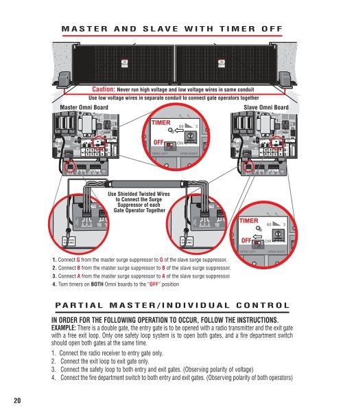
W4GCENTER SAFETY EXITAG B AM/S LinkP/N P/N Q410 Q410Patent Patent Pending Pending®CenterLoopSafetyLoopSYSTEM ONSENSORS1 3ExitLoopFIREDEPT.EXITLOOP1 3Fire DeptKey SwitchSTRIKEOPENSAFETYLOOPTIMEROFFOPEN LEFTRADIORECEIVERCENTERLOOPP/N Q410Patent Pending– +601 3ONOPEN RIGHTGATELOCKEDRESETMOTORClass 2SupplyStrike OpenRadio24 Volts DCPush Bu ton Receiver324 Volts DCDC-BACKUPPOWEROVERLOADMADE IN USAP/N P/N Q410 Q410Patent Patent Pending PendingW4CENTER SAFETY EXITGAG B AM/S Link®CenterLoopSafetyLoopSYSTEM ONSENSORS1 3FIREDEPT.EXITLOOP1 3STRIKEOPENSAFETYLOOPTIMEROFFOPEN LEFTRADIORECEIVERCENTERLOOPP/N Q410Patent Pending60ON1 3OPEN RIGHTGATELOCKEDRESETMOTOR– +ExitFire DeptStrike OpenRadio24 Volts DCLoopKey SwitchPush Bu ton Receiver3Class 2Supply24 Volts DCDC-BACKUPPOWEROVERLOADMADE IN USAMASTER AND SLAVE WITH TIMER OFFMaster Omni BoardCaution: Never run high voltage and low voltage wires in same conduitUse low voltage wires in separate conduit to connect gate operators togetherSlave Omni BoardTIMER603SENSORSENSORALARMALARMBMS LINKALARMSENSORREVERSESENSOROPENNSOROFFON1 3BMS LINKALARMSENSORREVERSESENSOROPENCENTER SAFETY EXITCOMMANDPROCESSEDCLOSE STOPOPEN LEFTOPEN RIGHTCENTER SAFETY EXITCOMMANDPROCESSEDCLOSE STOPOmniControl Surge SuppressorOmniControl Surge SuppressorUse Shielded Twisted Wiresto Connect the SurgeSuppressor of eachGate Operator TogetherG B AM/S LinkCenterLoopG B AM/S LinkCenterLoopTIMER603CHASSISGROUNDCHASSISGROUNDNSOROFFON1 31. Connect G from the master surge suppressor to G of the slave surge suppressor.2. Connect B from the master surge suppressor to B of the slave surge suppressor.3. Connect A from the master surge suppressor to A of the slave surge suppressor.4. Turn timers on BOTH Omni boards to the “OFF” positionOPEN LEFTOPEN RIGHTPARTIAL MASTER/INDIVIDUAL CONTROLIN ORDER FOR THE FOLLOWING OPERATION TO OCCUR, FOLLOW THE INSTRUCTIONS.EXAMPLE: There is a double gate, the entry gate is to be opened with a radio transmitter and the exit gatewith a free exit loop. Only one safety loop system is to open both gates, and a fire department switchshould open both gates at the same time.1. Connect the radio receiver to entry gate only.2. Connect the exit loop to exit gate only.3. Connect the safety loop to both entry and exit gates. (Observing polarity of voltage)4. Connect the fire department switch to both entry and exit gates. (Observing polarity of both operators)20