2516 L. Shen et al. / Composites Science <strong>and</strong> Technology 67 (2007) 2513–2520properties <strong>and</strong> geometry structures <strong>of</strong> <strong>the</strong> local compositepanel, i.e., <strong>the</strong> panel material sufficiently far away from<strong>the</strong> voltage contacts has no or little effect on <strong>the</strong> <strong>resistance</strong>between <strong>the</strong> two voltage contacts. However, <strong>the</strong> existingmethod <strong>of</strong> using Eq. (1) to derive <strong>the</strong> <strong>resistance</strong> changebetween two voltage contacts cannot be valid for <strong>the</strong> highlyorthotropic composite panel. This problem has not beenaddressed <strong>and</strong> will be investigated using numerical experimentsin this study.Multi-probe method: Ano<strong>the</strong>r application <strong>of</strong> <strong>the</strong> fourprobemethod was carried out by Todoraki et al. [16] whereit was called <strong>the</strong> multi-probe method, as shown in Fig. 2c.A constant electric current was charged from <strong>the</strong> left edge(1A <strong>and</strong> 2A) to <strong>the</strong> right edge (1E <strong>and</strong> 2E), <strong>and</strong> electricpotential changes at each electrode were measured wi<strong>the</strong>lectrodes 1E <strong>and</strong> 2E as <strong>the</strong> ground. So, <strong>the</strong> potentialchange in each electrode is actually <strong>the</strong> voltage change withrespect to electrode 1E or 2E as a fixed contact in a pair <strong>of</strong>voltage contacts.3. Numerical <strong>analysis</strong>3.1. A specimen without damageA 2-D strip specimen without delaminations is used tocarry out a numerical <strong>analysis</strong>, as shown in Fig. 3a. Thedimensions are similar to <strong>the</strong> specimen used by Wanget al. [10,11], i.e., L 0 = 200 mm, L 1 = 10 mm, L 2 =30mm, L 3 = 2 mm <strong>and</strong> H = 3.2 mm. The <strong>electrical</strong> conductivityin longitudinal direction is taken as r L =15X 1 mm 1<strong>and</strong> <strong>the</strong> <strong>electrical</strong> conductivity in <strong>the</strong> through-thicknessdirection r T is used as a variable to carry out a parametricstudy. For a composite panel <strong>the</strong> through-thickness conductivityr T (in <strong>the</strong> order <strong>of</strong> 10 3 X 1 mm 1 ) is usuallymuch smaller compared to <strong>the</strong> longitudinal conductivityr L . In order to measure <strong>the</strong> surface <strong>and</strong> oblique <strong>resistance</strong>saccording to <strong>the</strong> two- <strong>and</strong> four-probe methods, <strong>the</strong> electrodesA 0 to A 6 <strong>and</strong> B 0 to B 6 are mounted on both sides<strong>of</strong> <strong>the</strong> specimen (Fig. 3). The electrode width isL 3 = 2 mm <strong>and</strong> its conductivity is set at 10 8 X 1 mm 1 sothat <strong>the</strong> electrode <strong>resistance</strong>s can be assumed negligible.aL 3L 0L 1 L 2A 0 A 1 A 2 A 3 A 4 A 5 A 6B 0 B 1B 2 B 3 B 4 B 5 B 6bL 3L 0L 1 L 2A 0 A 1 A 2 A 3 A 4 A 5 A 6B 0 B 1B 2 B 3 B 4 B 5 B 6Fig. 3. 2-D specimen <strong>and</strong> electrode locations (a) without delamination<strong>and</strong> (b) with delamination.HHThe surface <strong>resistance</strong>s between <strong>the</strong> pairs <strong>of</strong> electrodesA 1 –A 5 <strong>and</strong> A 2 –A 4 <strong>and</strong> <strong>the</strong> oblique <strong>resistance</strong>s between electrodepairs A 1 –B 5 <strong>and</strong> A 2 –B 4 , namely R A1 A 5, R A2 A 4, <strong>and</strong>R A1 B 5, R A2 B 4, respectively, will be investigated using <strong>the</strong>two- <strong>and</strong> four-probe methods.According to <strong>the</strong> two-probe method, a unit current I isapplied as input to an electrode pair <strong>and</strong> <strong>the</strong> correspondingvoltage output V is obtained from numerical simulationusing <strong>the</strong> finite element method. Then, using Ohm’s law,<strong>the</strong> <strong>resistance</strong> R between <strong>the</strong> electrode pair is derived asR = V/I. Because no contact <strong>resistance</strong> is involved in <strong>the</strong>numerical experiment, <strong>the</strong> corresponding value <strong>of</strong> <strong>resistance</strong>can be used as target <strong>resistance</strong> to investigate <strong>the</strong>validity <strong>of</strong> <strong>the</strong> four-probe method.Based on <strong>the</strong> four-probe method, a unit current I isapplied as input to <strong>the</strong> electrode pair A 0 –A 6 or A 1 –A 5 ,<strong>and</strong> <strong>the</strong> voltage V between <strong>the</strong> electrode pair A 1 –A 5 orA 2 –A 4 as output is obtained from numerical experiments.Then, <strong>the</strong> surface <strong>resistance</strong> R between <strong>the</strong> electrode pairsA 1 –A 5 or A 2 –A 4 is derived as R = V/I according to Chung[18]. For <strong>the</strong> oblique <strong>resistance</strong> <strong>measurement</strong>s, instead, aunit current I is applied as input to <strong>the</strong> electrode pair A 0 –B 6 or A 1 –B 5 , <strong>and</strong> <strong>the</strong> voltage V between <strong>the</strong> electrode pairA 1 –B 5 or A 2 –B 4 as output is obtained from numerical experiments.Subsequently, <strong>the</strong> oblique <strong>resistance</strong> R between <strong>the</strong>electrode pairs A 1 –B 5 or A 2 –B 4 is derived as R = V/I.As mentioned previously, <strong>the</strong> four-probe method is validfor <strong>the</strong> <strong>resistance</strong> <strong>measurement</strong> if <strong>the</strong> current densitybetween <strong>the</strong> voltage contacts is uniform. The numericalexperiment is designed to investigate under what conditionsthis uniformity assumption can be met. For this purpose,various through-thickness conductivities such asfrom 0.001 to 20 X 1 mm 1 are used. It will be seen thatwhen <strong>the</strong> through-thickness conductivity is not small comparedto <strong>the</strong> longitudinal one, as is <strong>the</strong> case for isotropicmaterials, <strong>the</strong> four-probe method works well. O<strong>the</strong>rwise,its accuracy is poor.3.2. A specimen with a delaminationFig. 3b shows <strong>the</strong> same specimen as shown in Fig. 3a butwith a delamination located at its center with a length <strong>of</strong>25 mm. The longitudinal <strong>and</strong> through-thickness conductivitiesr L <strong>and</strong> r T are taken as r L =15X 1 mm 1 <strong>and</strong>r T = 0.005 X 1 mm 1 , respectively, which are close to <strong>the</strong>real values for <strong>the</strong> composite panel. The surface <strong>resistance</strong>sR A1 A 5<strong>and</strong> R A2 A 4, <strong>the</strong> oblique <strong>resistance</strong>s R A1 B 5<strong>and</strong> R A2 B 4, <strong>and</strong><strong>the</strong> through thickness <strong>resistance</strong> R A3 B 3are numericallyobtained according to <strong>the</strong> two-probe method. Since nocontact <strong>resistance</strong> is involved in <strong>the</strong> numerical calculationby <strong>the</strong> two-probe method, <strong>the</strong> <strong>resistance</strong>s obtained by <strong>the</strong>two-probe method are exact <strong>and</strong> serve to check <strong>the</strong> accuracy<strong>of</strong> <strong>the</strong> four-probe method. The corresponding <strong>resistance</strong>sare also obtained using <strong>the</strong> four-probe method,where <strong>the</strong> outside electrode pairs are used as <strong>the</strong> currentcontacts for <strong>the</strong> case <strong>of</strong> surface/oblique <strong>resistance</strong>. Forexample, to obtain R A1 A 5or R A2 B 4, <strong>the</strong> electrode pair A 0 –
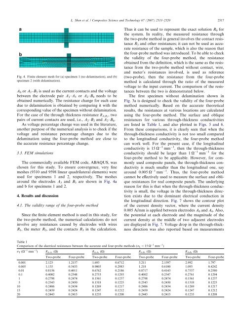
L. Shen et al. / Composites Science <strong>and</strong> Technology 67 (2007) 2513–2520 2517Fig. 4. Finite element mesh for (a) specimen 1 (no delamination), <strong>and</strong> (b)specimen 2 (with delamination).A 6 or A 1 –B 5 is used as <strong>the</strong> current contacts <strong>and</strong> <strong>the</strong> voltagebetween <strong>the</strong> electrode pair A 1 –A 5 or A 2 –B 4 needs to beobtained numerically. The <strong>resistance</strong> change for each casedue to delamination is obtained by comparing it with <strong>the</strong>corresponding value <strong>of</strong> <strong>the</strong> specimen without delamination.For <strong>the</strong> case <strong>of</strong> <strong>the</strong> through thickness <strong>resistance</strong> R A3 B 3, twopairs <strong>of</strong> current contacts are used, i.e., A 2 –B 2 <strong>and</strong> A 2 –B 4 .As voltage percentage change was used in <strong>the</strong> literature,ano<strong>the</strong>r purpose <strong>of</strong> <strong>the</strong> numerical <strong>analysis</strong> is to check if <strong>the</strong>voltage <strong>and</strong> <strong>resistance</strong> percentage changes due to <strong>the</strong>delamination using <strong>the</strong> four-probe method are close to<strong>the</strong> accurate <strong>resistance</strong> percentage change.3.3. FEM simulationsThe commercially available FEM code, ABAQUS, waschosen for this study. To ensure convergence, very finemeshes (9310 <strong>and</strong> 9598 linear quadrilateral elements) wereused for specimens 1 <strong>and</strong> 2, respectively. The meshesaround <strong>the</strong> electrodes A 3 <strong>and</strong> B 3 are shown in Fig. 4a<strong>and</strong> b for specimens 1 <strong>and</strong> 2.4. Results <strong>and</strong> discussion4.1. The validity range <strong>of</strong> <strong>the</strong> four-probe methodSince <strong>the</strong> finite element method is used in this study, for<strong>the</strong> two-probe method, <strong>the</strong> numerical calculations do notinvolve any <strong>resistance</strong>s caused by electrodes with wiresR 1 , <strong>the</strong> meter R 2 , <strong>and</strong> <strong>the</strong> contacts R 3 in <strong>the</strong> calculation.Thus it can be used to represent <strong>the</strong> exact solution R 0 for<strong>the</strong> system. In reality, <strong>the</strong> measured <strong>resistance</strong> through<strong>the</strong> two-probe method in general involves <strong>the</strong> contact <strong>resistance</strong>R 3 <strong>and</strong> o<strong>the</strong>r <strong>resistance</strong>s; it can not be used as accurate<strong>resistance</strong> <strong>of</strong> <strong>the</strong> sample, which is also <strong>the</strong> reason that<strong>the</strong> four-probe method was introduced. To be able to check<strong>the</strong> validity <strong>of</strong> <strong>the</strong> four-probe method, <strong>the</strong> <strong>resistance</strong>obtained from <strong>the</strong> definition, which is <strong>the</strong> same as <strong>the</strong> <strong>resistance</strong>from <strong>the</strong> two-probe method without contact, wire,<strong>and</strong> meter’s <strong>resistance</strong>s involved, is used as reference(two-probe), <strong>the</strong>n <strong>the</strong> <strong>resistance</strong> from <strong>the</strong> four-probemethod is calculated through <strong>the</strong> ratio <strong>of</strong> <strong>the</strong> measuredvoltage to <strong>the</strong> input current. The comparison <strong>of</strong> <strong>the</strong> <strong>resistance</strong>sbetween <strong>the</strong> two is demonstrated below.The first specimen without delamination shown inFig. 3a is designed to check <strong>the</strong> validity <strong>of</strong> <strong>the</strong> four-probemethod numerically. Based on <strong>the</strong> accurate <strong>the</strong>oreticalresults, <strong>the</strong> <strong>resistance</strong>s at various locations are calculatedusing <strong>the</strong> four-probe method. The surface <strong>and</strong> oblique<strong>resistance</strong>s for various through-thickness conductivitiesare listed in Table 1, <strong>and</strong> also plotted in Figs. 5 <strong>and</strong> 6.From <strong>the</strong>se comparisons, it is clearly seen that when <strong>the</strong>through-thickness conductivity is not too small comparedto <strong>the</strong> longitudinal conductivity, <strong>the</strong> four-probe methodcan work well. For <strong>the</strong> present case, if <strong>the</strong> longitudinalconductivity is 15 X 1 mm 1 , <strong>the</strong>n <strong>the</strong> through-thicknessconductivity should be larger than 1 X 1 mm 1 for <strong>the</strong>four-probe method to be applicable. However, for commonlyused composite panels, <strong>the</strong> through-thickness conductivityis much smaller than <strong>the</strong> longitudinal one, sayaround 0.005 X 1 mm 1 . Thus, <strong>the</strong> four-probe methodcannot be effectively used to measure <strong>the</strong> surface <strong>and</strong> oblique<strong>resistance</strong>s for real composite panels. The underlyingreason for this is that when <strong>the</strong> through-thickness conductivityis small, <strong>the</strong> voltage in <strong>the</strong> through-thickness directionexists due to <strong>the</strong> dominant <strong>electrical</strong> conduction in<strong>the</strong> longitudinal direction. Fig. 7 shows <strong>the</strong> contour plot<strong>of</strong> <strong>the</strong> current density vector, where <strong>the</strong> current density0.005 A/mm is applied between electrodes A 0 <strong>and</strong> A 6 . Also,<strong>the</strong> potential at each electrode <strong>and</strong> <strong>the</strong> magnitude <strong>of</strong> <strong>the</strong>current density at <strong>the</strong> middle <strong>of</strong> two adjacent electrodesare displayed in Fig. 7. Voltage drop in <strong>the</strong> through-thicknessdirection was also reported based on <strong>measurement</strong>sTable 1Comparison <strong>of</strong> <strong>the</strong> <strong>electrical</strong> <strong>resistance</strong>s between <strong>the</strong> accurate <strong>and</strong> four-probe methods (r L =15X 1 mm 1 )r T (X 1 mm 1 ) R (X) A1A5 R (X) A2A4 R (X) A1B5 R (X) A2B4Two-probe Four-probe Two-probe Four-probe Two-probe Four-probe Two-probe Four-probe0.001 2.123 1.2157 1.693 0.6712 3.211 2.1597 2.992 1.7970.005 1.135 0.5433 0.9005 0.2983 1.218 0.6100 1.093 0.42420.01 0.8156 0.4011 0.6762 0.2186 0.8717 0.4143 0.7537 0.25800.1 0.4002 0.2548 0.2753 0.1293 0.4002 0.2547 0.2761 0.12941 0.2798 0.2474 0.1561 0.1237 0.2798 0.2474 0.1561 0.12375 0.2543 0.2450 0.1318 0.1225 0.2543 0.2450 0.1318 0.122510 0.2486 0.2434 0.1269 0.1217 0.2486 0.2434 0.1269 0.121715 0.2459 0.2424 0.1247 0.1212 0.2459 0.2424 0.1247 0.121220 0.2443 0.2415 0.1235 0.1208 0.2443 0.2415 0.1235 0.1208