Modeling and analysis of the electrical resistance measurement of ...
Modeling and analysis of the electrical resistance measurement of ...
Modeling and analysis of the electrical resistance measurement of ...

Create successful ePaper yourself
Turn your PDF publications into a flip-book with our unique Google optimized e-Paper software.
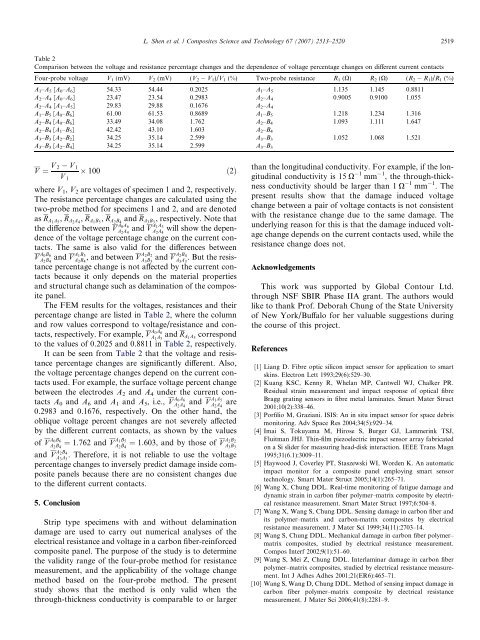
L. Shen et al. / Composites Science <strong>and</strong> Technology 67 (2007) 2513–2520 2519Table 2Comparison between <strong>the</strong> voltage <strong>and</strong> <strong>resistance</strong> percentage changes <strong>and</strong> <strong>the</strong> dependence <strong>of</strong> voltage percentage changes on different current contactsFour-probe voltage V 1 (mV) V 2 (mV) (V 2 V 1 )/V 1 (%) Two-probe <strong>resistance</strong> R 1 (X) R 2 (X) (R 2 R 1 )/R 1 (%)A 1 –A 5 [A 0 –A 6 ] 54.33 54.44 0.2025 A 1 –A 5 1.135 1.145 0.8811A 2 –A 4 [A 0 –A 6 ] 23.47 23.54 0.2983 A 2 –A 4 0.9005 0.9100 1.055A 2 –A 4 [A 1 –A 5 ] 29.83 29.88 0.1676 A 2 –A 4A 1 –B 5 [A 0 –B 6 ] 61.00 61.53 0.8689 A 1 –B 5 1.218 1.234 1.316A 2 –B 4 [A 0 –B 6 ] 33.49 34.08 1.762 A 2 –B 4 1.093 1.111 1.647A 2 –B 4 [A 1 –B 5 ] 42.42 43.10 1.603 A 2 –B 4A 3 –B 3 [A 2 –B 2 ] 34.25 35.14 2.599 A 3 –B 3 1.052 1.068 1.521A 3 –B 3 [A 2 –B 4 ] 34.25 35.14 2.599 A 3 –B 3V ¼ V 2 V 1 100 ð2ÞV 1where V 1 , V 2 are voltages <strong>of</strong> specimen 1 <strong>and</strong> 2, respectively.The <strong>resistance</strong> percentage changes are calculated using <strong>the</strong>two-probe method for specimens 1 <strong>and</strong> 2, <strong>and</strong> are denotedas R A1 A 5, R A2 A 4, R A1 B 5, R A2 B 4<strong>and</strong> R A3 B 3, respectively. Note that<strong>the</strong> difference between V A 0A 6A 2 A 4<strong>and</strong> V A 1A 5A 2 A 4will show <strong>the</strong> dependence<strong>of</strong> <strong>the</strong> voltage percentage change on <strong>the</strong> current contacts.The same is also valid for <strong>the</strong> differences betweenV A 0B 6A 2 B 4<strong>and</strong> V A 1B 5A 2 B 4, <strong>and</strong> between V A 2B 2A 3 B 3<strong>and</strong> V A 2B 4A 3 A 3. But <strong>the</strong> <strong>resistance</strong>percentage change is not affected by <strong>the</strong> current contactsbecause it only depends on <strong>the</strong> material properties<strong>and</strong> structural change such as delamination <strong>of</strong> <strong>the</strong> compositepanel.The FEM results for <strong>the</strong> voltages, <strong>resistance</strong>s <strong>and</strong> <strong>the</strong>irpercentage change are listed in Table 2, where <strong>the</strong> column<strong>and</strong> row values correspond to voltage/<strong>resistance</strong> <strong>and</strong> contacts,respectively. For example, V A 0A 6A 1 A 5<strong>and</strong> R A1 A 5correspondto <strong>the</strong> values <strong>of</strong> 0.2025 <strong>and</strong> 0.8811 in Table 2, respectively.It can be seen from Table 2 that <strong>the</strong> voltage <strong>and</strong> <strong>resistance</strong>percentage changes are significantly different. Also,<strong>the</strong> voltage percentage changes depend on <strong>the</strong> current contactsused. For example, <strong>the</strong> surface voltage percent changebetween <strong>the</strong> electrodes A 2 <strong>and</strong> A 4 under <strong>the</strong> current contactsA 0 <strong>and</strong> A 6 <strong>and</strong> A 1 <strong>and</strong> A 5 , i.e., V A 0A 6A 2 A 4<strong>and</strong> V A 1A 5A 2 A 4are0.2983 <strong>and</strong> 0.1676, respectively. On <strong>the</strong> o<strong>the</strong>r h<strong>and</strong>, <strong>the</strong>oblique voltage percent changes are not severely affectedby <strong>the</strong> different current contacts, as shown by <strong>the</strong> values<strong>of</strong> V A 0B 6A 2 B 4¼ 1:762 <strong>and</strong> V A 1B 5A 2 B 4¼ 1:603, <strong>and</strong> by those <strong>of</strong> V A 2B 2A 3 B 3<strong>and</strong> V A 2B 4A 3 A 3. Therefore, it is not reliable to use <strong>the</strong> voltagepercentage changes to inversely predict damage inside compositepanels because <strong>the</strong>re are no consistent changes dueto <strong>the</strong> different current contacts.5. ConclusionStrip type specimens with <strong>and</strong> without delaminationdamage are used to carry out numerical analyses <strong>of</strong> <strong>the</strong><strong>electrical</strong> <strong>resistance</strong> <strong>and</strong> voltage in a carbon fiber-reinforcedcomposite panel. The purpose <strong>of</strong> <strong>the</strong> study is to determine<strong>the</strong> validity range <strong>of</strong> <strong>the</strong> four-probe method for <strong>resistance</strong><strong>measurement</strong>, <strong>and</strong> <strong>the</strong> applicability <strong>of</strong> <strong>the</strong> voltage changemethod based on <strong>the</strong> four-probe method. The presentstudy shows that <strong>the</strong> method is only valid when <strong>the</strong>through-thickness conductivity is comparable to or largerthan <strong>the</strong> longitudinal conductivity. For example, if <strong>the</strong> longitudinalconductivity is 15 X 1 mm 1 , <strong>the</strong> through-thicknessconductivity should be larger than 1 X 1 mm 1 . Thepresent results show that <strong>the</strong> damage induced voltagechange between a pair <strong>of</strong> voltage contacts is not consistentwith <strong>the</strong> <strong>resistance</strong> change due to <strong>the</strong> same damage. Theunderlying reason for this is that <strong>the</strong> damage induced voltagechange depends on <strong>the</strong> current contacts used, while <strong>the</strong><strong>resistance</strong> change does not.AcknowledgementsThis work was supported by Global Contour Ltd.through NSF SBIR Phase IIA grant. The authors wouldlike to thank Pr<strong>of</strong>. Deborah Chung <strong>of</strong> <strong>the</strong> State University<strong>of</strong> New York/Buffalo for her valuable suggestions during<strong>the</strong> course <strong>of</strong> this project.References[1] Liang D. Fibre optic silicon impact sensor for application to smartskins. Electron Lett 1993;29(6):529–30.[2] Kuang KSC, Kenny R, Whelan MP, Cantwell WJ, Chalker PR.Residual strain <strong>measurement</strong> <strong>and</strong> impact response <strong>of</strong> optical fibreBragg grating sensors in fibre metal laminates. Smart Mater Struct2001;10(2):338–46.[3] Porfilio M, Graziani. ISIS: An in situ impact sensor for space debrismonitoring. Adv Space Res 2004;34(5):929–34.[4] Imai S, Tokuyama M, Hirose S, Burger GJ, Lammerink TSJ,Fluitman JHJ. Thin-film piezoelectric impact sensor array fabricatedon a Si slider for measuring head-disk interaction. IEEE Trans Magn1995;31(6.1):3009–11.[5] Haywood J, Coverley PT, Staszewski WI, Worden K. An automaticimpact monitor for a composite panel employing smart sensortechnology. Smart Mater Struct 2005;14(1):265–71.[6] Wang X, Chung DDL. Real-time monitoring <strong>of</strong> fatigue damage <strong>and</strong>dynamic strain in carbon fiber polymer–matrix composite by <strong>electrical</strong><strong>resistance</strong> <strong>measurement</strong>. Smart Mater Struct 1997;6:504–8.[7] Wang X, Wang S, Chung DDL. Sensing damage in carbon fiber <strong>and</strong>its polymer–matrix <strong>and</strong> carbon-matrix composites by <strong>electrical</strong><strong>resistance</strong> <strong>measurement</strong>. J Mater Sci 1999;34(11):2703–14.[8] Wang S, Chung DDL. Mechanical damage in carbon fiber polymer–matrix composites, studied by <strong>electrical</strong> <strong>resistance</strong> <strong>measurement</strong>.Compos Interf 2002;9(1):51–60.[9] Wang S, Mei Z, Chung DDL. Interlaminar damage in carbon fiberpolymer–matrix composites, studied by <strong>electrical</strong> <strong>resistance</strong> <strong>measurement</strong>.Int J Adhes Adhes 2001;21(ER6):465–71.[10] Wang S, Wang D, Chung DDL. Method <strong>of</strong> sensing impact damage incarbon fiber polymer–matrix composite by <strong>electrical</strong> <strong>resistance</strong><strong>measurement</strong>. J Mater Sci 2006;41(8):2281–9.