d-lab.2, d-lab.2plus, netlab.2plus - D-Lab 1
d-lab.2, d-lab.2plus, netlab.2plus - D-Lab 1
d-lab.2, d-lab.2plus, netlab.2plus - D-Lab 1

You also want an ePaper? Increase the reach of your titles
YUMPU automatically turns print PDFs into web optimized ePapers that Google loves.
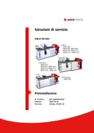
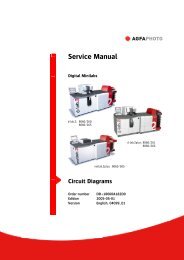
Operation ManualDigital Minilabsd-<strong>lab.2</strong>:8060/260,8060/803, 8060/804,8060/270, 8060/272,8060/157 + 8060/255d-<strong>lab.2</strong>plus:8060/2618060/813, 8060/8148060/271, 8060/2738060/158 + 8060/255net<strong>lab.2</strong>plus:8060/505OperationOrder number DD+18060A162D0Edition 2005-05-01Version English, 04092_01
Modification HistoryVersion Edition Modifications04092_00 2004-10-01 Combination of the Operation Manual – Operationfor the machines d-<strong>lab.2</strong>, d-<strong>lab.2</strong>plus, andnet<strong>lab.2</strong>plus;Update to Software Version 8.004092_01 2005_05_01 Update to Software Version 8.5© 2005 AgfaPhoto GmbH. Alle Rechte vorbehalten.No part of these instructions may be reproduced, copied, or transmitted in anyform or by any means without prior written permission by AgfaPhoto GmbH.AgfaPhoto is used under license of Agfa-Gevaert AG
d-<strong>lab.2</strong>, d-<strong>lab.2</strong>plus, net<strong>lab.2</strong>plus: OperationContentsContents1 Introduction........................................................................................................................1-i1.1 Applied Standards and Rules....................................................................................................................................1-11.2 Explanations for the Operation and Service Manual .......................................................................................1-21.2.1 Available Documentation.......................................................................................................................1-21.2.2 Guideline for the User..............................................................................................................................1-31.2.3 Conventions.................................................................................................................................................1-41.2.3.1 Pictographs......................................................................................................................................1-41.2.3.2 Text styles ........................................................................................................................................1-41.2.3.3 Safety notes.....................................................................................................................................1-51.3 Legal Situation ...............................................................................................................................................................1-61.3.1 Manufacturer Information......................................................................................................................1-61.3.2 Copyright ......................................................................................................................................................1-61.3.3 Warranty........................................................................................................................................................1-71.3.3.1 Liability of the Owner ..................................................................................................................1-71.3.3.2 Warranty and Liability .................................................................................................................1-71.3.3.3 Exclusion of Liability ....................................................................................................................1-81.3.4 Appropriate Use..........................................................................................................................................1-81.3.5 Inappropriate Use ......................................................................................................................................1-81.4 Consumables and Spare Parts..................................................................................................................................1-91.5 Hotline...............................................................................................................................................................................1-91.6 Safety Notes and Rules............................................................................................................................................1-101.6.1 General .......................................................................................................................................................1-101.6.2 In Operation..............................................................................................................................................1-111.6.3 Handling of Chemicals .........................................................................................................................1-111.6.4 Service / Repair Routines ...................................................................................................................1-121.6.5 Disposal of the Machine......................................................................................................................1-121.6.6 Warnings and Information <strong>Lab</strong>els on the Machine ...................................................................1-131.7 Transport, Installation, First Operation ..............................................................................................................1-221.8 Storage...........................................................................................................................................................................1-221.8.1 Chemicals..................................................................................................................................................1-221.8.2 Photographic Paper ...............................................................................................................................1-222 General Description, Work Routines and Operation ..............................................................2-i2.1 General Description......................................................................................................................................................2-12.2 Product Description......................................................................................................................................................2-72.2.1 Corresponding Film Types and Images .............................................................................................2-72.2.2 Image Editing..............................................................................................................................................2-72.3 Operation Routines.......................................................................................................................................................2-82.3.1 Drive BayApplies only to d-<strong>lab.2</strong>plus, net<strong>lab.2</strong>plus ................................................................................................2-82.3.2 ScannerApplies only to d-<strong>lab.2</strong>/2plus ....................................................................................................................2-92.3.3 Main computer ........................................................................................................................................2-102.3.4 Printer .........................................................................................................................................................2-112.3.5 Paper Processor.......................................................................................................................................2-122.3.6 Sorter...........................................................................................................................................................2-132.3.7 Densitometer ...........................................................................................................................................2-142.4 Controls on the Minilab...........................................................................................................................................2-152.4.1 Keys and Pilot Lamps............................................................................................................................2-152.4.2 Touchscreen Monitor ............................................................................................................................2-16AgfaPhoto 2005-05-01 / PN 04092_01 0-i
Contentsd-<strong>lab.2</strong>, d-<strong>lab.2</strong>plus, net<strong>lab.2</strong>plus: Operation2.4.3 Main Breaker and Ground Fault Interrupter................................................................................. 2-172.5 Switching the Machine On and Off..................................................................................................................... 2-182.5.1 Preparations Prior to Switch-on........................................................................................................ 2-182.5.2 Automatic Switch-On (Timer) ............................................................................................................ 2-182.5.3 Switching On with the ON Key......................................................................................................... 2-192.5.4 Switching the Machine On and Off with the Main Breaker................................................... 2-202.5.5 System Start............................................................................................................................................. 2-222.5.6 User Login ................................................................................................................................................. 2-222.5.7 The Start Screen...................................................................................................................................... 2-232.5.8 Log-in of Another User ......................................................................................................................... 2-242.5.9 End of Work and Shutdown................................................................................................................ 2-242.5.9.1 Sleep Mode...................................................................................................................................2-252.5.9.2 Switching the Machine Off .....................................................................................................2-252.6 Screen Layout and Controls on the Screen...................................................................................................... 2-272.6.1 Information Area..................................................................................................................................... 2-282.6.2 Buttons....................................................................................................................................................... 2-302.6.3 Pulldown Menus..................................................................................................................................... 2-312.6.4 Popup Windows ...................................................................................................................................... 2-322.6.5 Input Screens........................................................................................................................................... 2-342.6.5.1 Entering Text ................................................................................................................................2-342.6.5.2 Entering Numbers.......................................................................................................................2-352.6.6 Reorder KeyboardApplies only to d-<strong>lab.2</strong>/2plus................................................................................................................. 2-362.7 Main Menus ................................................................................................................................................................. 2-382.8 Calling Up Info............................................................................................................................................................ 2-432.8.1 Film Drive InfoApplies only to d-<strong>lab.2</strong>/2plus................................................................................................................. 2-452.8.2 Printer Info................................................................................................................................................ 2-462.8.3 Paper Processor Info ............................................................................................................................. 2-472.8.4 Order Info .................................................................................................................................................. 2-482.8.5 Version Info .............................................................................................................................................. 2-492.8.6 Displaying the Error List....................................................................................................................... 2-502.9 Activating Help ........................................................................................................................................................... 2-512.10 Ejecting the ZIP .......................................................................................................................................................... 2-533 Changing Chemicals............................................................................................................ 3-i3.1 Safety Information........................................................................................................................................................3-13.2 Chemical Sets ................................................................................................................................................................3-33.3 Changing Chemical Solutions (MSC/d-lab Chemicals) .................................................................................3-43.4 Mixing Replenisher Chemicals (d-<strong>lab.2</strong> Easy Paper Box)............................................................................ 3-103.5 Settings and Tests for the Chemicals................................................................................................................. 3-114 Settings and Configurations ................................................................................................ 4-i4.1 Overview...........................................................................................................................................................................4-14.2 Defining the User Interface, Defining Users, Assigning Rights...................................................................4-54.2.1 Defining the User Interface...................................................................................................................4-54.2.2 Defining Users and User Rights ...........................................................................................................4-64.2.2.1 Defining a New User ................................................................................................................... 4-74.2.2.2 Changing the Settings for an Existing User........................................................................ 4-94.2.2.3 Overview: Rights, which can be Assigned to a User......................................................4-104.2.2.4 Defining a User as Standard User.........................................................................................4-114.2.2.5 Changing the User .....................................................................................................................4-114.2.3 Deleting a User ....................................................................................................................................... 4-114.3 Defining Paper Width, Surfaces and Cut Lengths ......................................................................................... 4-124.3.1 Defining Paper Widths ......................................................................................................................... 4-120-ii 2005-05-01 / PN 04092_01 AgfaPhoto
d-<strong>lab.2</strong>, d-<strong>lab.2</strong>plus, net<strong>lab.2</strong>plus: OperationContents4.3.2 Deleting Paper Widths .........................................................................................................................4-144.3.3 Defining Paper Surfaces.......................................................................................................................4-144.3.4 Renaming Surfaces ................................................................................................................................4-164.3.5 Deleting Surfaces ...................................................................................................................................4-164.3.6 Paper Codes according to AgfaPhoto Standard ..........................................................................4-174.3.7 Defining Cut Lengths ............................................................................................................................4-184.3.8 Overview: Print Sizes ............................................................................................................................4-194.3.9 Deleting Cut Lengths............................................................................................................................4-204.4 Entering Machine Settings .....................................................................................................................................4-214.4.1 Setting Date and Time..........................................................................................................................4-224.4.2 Setting the Timer: Start and Shutdown..........................................................................................4-234.4.3 Defining the Standard User ................................................................................................................4-264.4.4 Installing / Activating Software .......................................................................................................4-274.4.4.1 Activating Software ...................................................................................................................4-274.4.4.2 Installing Software from CD...................................................................................................4-294.4.5 Printer Settings .......................................................................................................................................4-304.4.6 Scanner Settings (Scratch Correction, Scanning Crop)Applies only to d-<strong>lab.2</strong>/2plus .................................................................................................................4-324.4.7 Paper Processor Settings.....................................................................................................................4-344.4.7.1 Setting the Replenishment Rates ........................................................................................4-344.4.7.2 Setting the Temperatures and Calibrating the Sensors ...............................................4-364.4.7.3 Calibrating the Water Pumps ................................................................................................4-384.4.8 Other Settings..........................................................................................................................................4-434.4.8.1 General settings..........................................................................................................................4-444.4.8.2 Settings for negative printing(only for d-<strong>lab.2</strong>/2plus)............................................................................................................4-454.4.8.3 Settings for digital orders........................................................................................................4-464.4.8.4 The dTFS function (digital Total Film Scanning: Image enhancementin digital print files)...................................................................................................................4-474.4.8.5 Autosave settings.......................................................................................................................4-494.5 Adjusting the Production Balance.......................................................................................................................4-504.5.1 General Information Regarding the Production Balance........................................................4-534.5.2 Setting the Correction Impact (for Color Negatives and Digital).........................................4-544.5.3 Setting Sharpness - Edges (for Color Negatives and Digital) ................................................4-554.5.4 Setting the Saturation (for Color Negatives and Digital) ........................................................4-564.5.5 Setting Sharpness - Grain (for Color Negatives and Digital)..................................................4-574.5.6 Area Contrast (for Color Negatives and Digital)..........................................................................4-584.5.7 Setting Detail Contrast (for Color Negatives and Digital).......................................................4-594.5.8 Brightness correction (for color negatives and digital)............................................................4-604.5.9 Setting Color and Density Corrections (Digital) .........................................................................4-614.5.10 Activating / Deactivating the Contrast Management (only for Color Negative)Applies only to d-<strong>lab.2</strong>/2plus .................................................................................................................4-614.5.11 Red-eye correction (for color negatives and digital).................................................................4-614.5.12 Using TFS (only for Color Negatives)Applies only to d-<strong>lab.2</strong>/2plus .................................................................................................................4-634.5.13 Panorama Identification (only for Color Negatives)Applies only to d-<strong>lab.2</strong>/2plus .................................................................................................................4-654.5.14 Color / Density Logic (TFS; only for Color Negative)Applies only to d-<strong>lab.2</strong>/2plus .................................................................................................................4-654.5.15 Setting TFS Color (only for Color Negatives)Applies only to d-<strong>lab.2</strong>/2plus .................................................................................................................4-664.5.15.1 Dominant Parameters...............................................................................................................4-664.5.15.2 Parameters for Artificial Light Detection...........................................................................4-684.5.15.3 Parameter for Shift Correction...............................................................................................4-70AgfaPhoto 2005-05-01 / PN 04092_01 0-iii
Contentsd-<strong>lab.2</strong>, d-<strong>lab.2</strong>plus, net<strong>lab.2</strong>plus: Operation4.5.16 Setting TFS Density (only for Color Negatives)Applies only to d-<strong>lab.2</strong>/2plus................................................................................................................. 4-714.5.17 Setting the Selector Logic (only for Color Negatives)Applies only to d-<strong>lab.2</strong>/2plus................................................................................................................. 4-734.5.18 Setting Color and DX Corrections (for Color Negatives)Applies only to d-<strong>lab.2</strong>/2plus................................................................................................................. 4-754.5.18.1 Color Corrections........................................................................................................................4-754.5.18.2 DX Corrections ............................................................................................................................4-764.6 Settings for Network Orders .................................................................................................................................. 4-784.6.1 Settings for Remote Orders: File Print ........................................................................................... 4-794.6.2 Settings for Remote Orders: Autosave ...........................................................................................4-804.6.3 Settings for Network Orders............................................................................................................... 4-814.6.4 Settings for d-workflow........................................................................................................................ 4-824.7 Defining and Editing Print Configurations ....................................................................................................... 4-844.7.1 Defining and Editing Paper Configurations.................................................................................. 4-854.7.2 Defining and Editing the Backprint Configurations .................................................................. 4-874.7.3 Indexprint Configurations.................................................................................................................... 4-934.7.3.1 Importing Indexprint Layouts.................................................................................................4-934.7.3.2 Defining and Editing a Indexprint Configuration:...........................................................4-944.7.4 Defining and Editing Correction Configurations ........................................................................ 4-974.7.5 Defining and Editing Autosave Configurations.........................................................................4-1004.7.6 Defining and Editing a Front Print Configuration ....................................................................4-1044.7.7 Combiprint Configurations ...............................................................................................................4-1064.7.7.1 Importing Combiprint Layouts............................................................................................ 4-1064.7.7.2 Defining and Editing a Combiprint Configurations:.................................................... 4-1074.8 Defining and Editing Order Configurations....................................................................................................4-1094.8.1 Defining and Editing Order Configurations of the Single Type...........................................4-1124.8.1.1 Film Mask: 135, 120, 110Applies only to d-<strong>lab.2</strong>/2plus............................................................................................. 4-1124.8.1.2 Film Mask: File Print............................................................................................................... 4-1134.8.1.3 Film Mask: IX240Applies only to d-<strong>lab.2</strong>/2plus............................................................................................. 4-1154.8.1.4 Film Mask: SlideApplies only to d-<strong>lab.2</strong>/2plus............................................................................................. 4-1174.8.2 Defining and Editing Order Configurations of the Package Type ......................................4-1184.8.3 Defining and Editing Order Configurations of the Combiprint Type.................................4-1204.8.3.1 Film Mask: 135, 120, 110Applies only to d-<strong>lab.2</strong>/2plus............................................................................................. 4-1204.8.3.2 Film Mask: IX240, SlideApplies only to d-<strong>lab.2</strong>/2plus............................................................................................. 4-1214.8.3.3 Film Mask: File Print............................................................................................................... 4-1224.8.4 Defining and Editing Order Configurations of the Reproduction Type ............................4-1234.8.5 Defining a Configuration as Standard Configuration..............................................................4-1254.9 Deleting a Print or Order Configuration..........................................................................................................4-1274.10 Pricing Configurations............................................................................................................................................4-1284.11 Save and Load Settings and Configurations..................................................................................................4-1295 Tests.................................................................................................................................. 5-i5.1 Overview...........................................................................................................................................................................5-15.2 Printer Tests:Paper Balance Test (PBL) and Master Balance Test (MBL)..................................................5-25.2.1 Conditions for Printing an MBL and PBL..........................................................................................5-35.2.2 Initial PBL and MBL after the Machine Installation.....................................................................5-45.2.3 Daily Calibration with the MBL............................................................................................................5-55.2.4 Daily Calibration without MBL (Exception) .....................................................................................5-60-iv 2005-05-01 / PN 04092_01 AgfaPhoto
d-<strong>lab.2</strong>, d-<strong>lab.2</strong>plus, net<strong>lab.2</strong>plus: OperationContents5.2.5 Calibration of a New Paper Configuration in Case of Emulsion Changesor Changes in a Paper Configuration (not Master Paper)...........................................................5-65.2.6 Calibrating a New Paper Configuration or Changing the Emulsion(Master Paper).............................................................................................................................................5-75.2.7 Complete New Calibration.....................................................................................................................5-85.3 Printing a PBL Test .......................................................................................................................................................5-95.3.1 General Procedure.....................................................................................................................................5-95.3.2 PBL Test with Laser Point....................................................................................................................5-115.3.3 Copying Laser Points during Calibration of a Paper Configuration.....................................5-125.3.4 Default Setting of Maximum Densities and Calibration Factors..........................................5-145.3.5 When Should Maximum Densities Be Changed?.......................................................................5-155.3.6 Changing the Maximum Densities of a Paper.............................................................................5-165.3.7 Changing the Gray Balance of the Internal Densitometer.....................................................5-195.4 Printing an MBL Test.................................................................................................................................................5-205.5 Calibrating the Scanner (Pixel Correction, PIKO)Applies only to d-<strong>lab.2</strong>/2plus.....................................................................................................................................5-215.6 Checking the Process (Chemical control strip test)......................................................................................5-236 Production..........................................................................................................................6-i6.1 Order Handling – Overview.......................................................................................................................................6-16.1.1 Preparations Before Production Start ................................................................................................6-16.1.2 Print Modes..................................................................................................................................................6-26.1.2.1 Print modes and Possible Film and File Formats ..............................................................6-26.1.2.2 Printing without or with Preview.............................................................................................6-46.1.2.3 Order Configurations....................................................................................................................6-56.1.2.4 Changing to another print mode.............................................................................................6-56.1.3 Order Handling ...........................................................................................................................................6-66.1.4 Order Tracing............................................................................................................................................6-106.1.5 Changing the Order Number..............................................................................................................6-106.1.6 Select or Change Configuration........................................................................................................6-116.1.6.1 Configuration Types for Print Orders...................................................................................6-116.1.6.2 Display of the Current Configuration..................................................................................6-126.1.6.3 Changing the Configuration for the Complete Order....................................................6-166.1.6.4 Changing the Configuration for Individual Images of an OrderApplies only to d-<strong>lab.2</strong>/2plus................................................................................................6-176.1.6.5 Selecting Another Configuration for the Complete Order...........................................6-186.1.6.6 Selecting Another Configuration for Individual Images of an OrderApplies only to d-<strong>lab.2</strong>/2plus................................................................................................6-186.1.7 Inserting Films and SlidesApplies only to d-<strong>lab.2</strong>/2plus .................................................................................................................6-196.1.8 End of Order (Automatic / Manual).................................................................................................6-206.1.9 Special Print Products and Motif Groups ......................................................................................6-216.1.9.1 Black and White Prints.............................................................................................................6-216.1.9.2 Sepia Prints and Prints with Color Cast .............................................................................6-236.1.9.3 ReorderApplies only to d-<strong>lab.2</strong>/2plus of Black/White Films / Films WithoutExtended DX Code.....................................................................................................................6-236.1.9.4 Portraits..........................................................................................................................................6-246.1.9.5 Border Prints ................................................................................................................................6-246.2 Preparing the Machine for Different Orders.....................................................................................................6-266.2.1 Changing the Paper Magazine and Loading Paper ...................................................................6-266.2.1.1 Removing the Paper Magazine.............................................................................................6-276.2.1.2 Removing the Paper..................................................................................................................6-276.2.1.3 Adjusting the Paper Widths....................................................................................................6-286.2.1.4 Loading Paper into the Magazine ........................................................................................6-29AgfaPhoto 2005-05-01 / PN 04092_01 0-v
Contentsd-<strong>lab.2</strong>, d-<strong>lab.2</strong>plus, net<strong>lab.2</strong>plus: Operation6.2.1.5 Coding the Paper Magazine ...................................................................................................6-306.2.1.6 Inserting a Paper Magazine....................................................................................................6-306.2.2 Changing the Mirror BoxApplies only to d-<strong>lab.2</strong>/2plus................................................................................................................. 6-316.2.3 Changing the Film CarrierApplies only to d-<strong>lab.2</strong>/2plus................................................................................................................. 6-326.3 Printing .......................................................................................................................................................................... 6-336.3.1 Working with the Autoprint ModeApplies only to d-<strong>lab.2</strong>/2plus................................................................................................................. 6-336.3.1.1 Activating the Print Mode and Selecting a Configuration ..........................................6-336.3.1.2 Autoprint without Preview ......................................................................................................6-346.3.1.3 Autoprint with Preview.............................................................................................................6-356.3.2 Working with Reorder ModeApplies only to d-<strong>lab.2</strong>/2plus................................................................................................................. 6-406.3.2.1 Activating the Print Mode and Editing a Reorder List ..................................................6-406.3.2.2 Reorder without Preview .........................................................................................................6-446.3.2.3 Reorder with Preview................................................................................................................6-466.3.3 Working with Manual Positioning ModeApplies only to d-<strong>lab.2</strong>/2plus................................................................................................................. 6-506.3.3.1 Activating the Print Mode.......................................................................................................6-516.3.3.2 Image Editing and Printing.....................................................................................................6-526.3.4 Working with File Print Mode ........................................................................................................... 6-556.3.4.1 General Information ..................................................................................................................6-556.3.4.2 Using dTFS: Automatic Color and Density Corrections.................................................6-576.3.4.3 Load Image Files from Storage Media................................................................................6-586.3.4.4 Saving Digital Orders ................................................................................................................6-616.3.4.5 Loading a Saved Digital Order...............................................................................................6-626.3.4.6 Delete the Saved Digital Order .............................................................................................6-646.3.4.7 Printing File Prints without Preview....................................................................................6-656.3.4.8 Printing File Prints with Preview ..........................................................................................6-676.3.5 Working with Slide Print ModeApplies only to d-<strong>lab.2</strong>/2plus................................................................................................................. 6-726.3.5.1 Activating the Print Mode.......................................................................................................6-726.3.66.3.5.2 Image Editing and Printing.....................................................................................................6-74Working with the Slide Film Print ModeApplies only to d-<strong>lab.2</strong>/2plus................................................................................................................. 6-766.3.6.1 Activating the Print Mode.......................................................................................................6-766.3.6.2 Image Editing and Printing.....................................................................................................6-776.4 The Functions Image Editing and Special ........................................................................................................ 6-806.4.1 Image Editing........................................................................................................................................... 6-816.4.1.1 Activation ......................................................................................................................................6-816.4.1.2 Making Color and Density Corrections...............................................................................6-826.4.1.3 Cropping ........................................................................................................................................6-836.4.1.4 Image Improvement..................................................................................................................6-846.4.2 Special........................................................................................................................................................ 6-856.4.2.1 Enter and Format Text for the Exposure.............................................................................6-866.4.2.2 Setting a Border..........................................................................................................................6-886.4.3 Saving an Image as File....................................................................................................................... 6-896.5 Manual red eyes correction ................................................................................................................................... 6-916.6 Index prints................................................................................................................................................................... 6-956.6.1 Index Prints in the Different Print Modes..................................................................................... 6-966.6.2 Sequence and Designations of the Thumbnails......................................................................... 6-976.6.3 Quantity, Size, and Aspect Ratio of the Thumbnails ................................................................ 6-976.6.4 Print Index Print Only........................................................................................................................... 6-980-vi 2005-05-01 / PN 04092_01 AgfaPhoto
d-<strong>lab.2</strong>, d-<strong>lab.2</strong>plus, net<strong>lab.2</strong>plus: OperationContents6.7 Saving Images with Autosave ...............................................................................................................................6-996.7.1 Printing and Saving Images ............................................................................................................ 6-1006.7.2 Save Images Only, Without Printing............................................................................................ 6-1016.8 Network Orders ........................................................................................................................................................ 6-1026.8.1 The Minilab in a Network................................................................................................................. 6-1026.8.2 Manual Start of Network Orders.................................................................................................... 6-1046.8.3 Automatic Start of Network Orders .............................................................................................. 6-1056.8.4 Deleting Network Orders.................................................................................................................. 6-1066.9 Printing Price <strong>Lab</strong>els (Option) ........................................................................................................................... 6-1076.10 Saving and Displaying Statistics....................................................................................................................... 6-1086.10.1 Displaying Statistics........................................................................................................................... 6-1086.10.2 Saving Statistics................................................................................................................................... 6-1096.11 Clickrate (Option) .................................................................................................................................................... 6-1107 Troubleshooting..................................................................................................................7-i7.1 Avoiding Problems........................................................................................................................................................7-17.2 Display of Error Messages..........................................................................................................................................7-27.3 Activating Help for Error Messages ........................................................................................................................7-37.4 Problems During ScanningApplies only to d-<strong>lab.2</strong>/2plus........................................................................................................................................7-37.5 The Machine Fails to React to Operator Inputs.................................................................................................7-47.5.1 Resetting the Machine with the Stop Button................................................................................7-57.5.2 Resetting the Machine with the ON key..........................................................................................7-67.6 Procedure if an Error Occurs .....................................................................................................................................7-87.6.1 General Procedure.....................................................................................................................................7-87.6.2 Procedure for Unsolved Errors ..............................................................................................................7-87.6.3 Screen Remains Gray for More Than 3 Minutes after Reset.....................................................7-97.6.4 Image Processing Errors.......................................................................................................................7-107.6.5 Paper Processor and Printer Errors...................................................................................................7-117.6.6 Printer Errors.............................................................................................................................................7-127.6.7 Other Errors...............................................................................................................................................7-127.7 Removing a Paper JamApplies to d-<strong>lab.2</strong> ..........................................................................................................................................................7-137.7.1 General procedure..................................................................................................................................7-137.7.2 Paper Jam in the Printer ......................................................................................................................7-157.7.3 Paper Jam in the Transport Unit (TU) ..............................................................................................7-167.7.4 Paper Jam in the Transfer Positions Transport Unit (TU) and Print Engine (PE)..............7-207.7.5 Paper Jam in the Print Engine (PE)..................................................................................................7-217.7.6 Paper Jam between Transport Unit (TU) andLane Distributor (LD)..............................................................................................................................7-237.7.7 Paper Jam in the Lane Distributor (LD) ..........................................................................................7-247.7.8 Paper Jam between Lane Distributor (LD) andSheet Transfer (ST)..................................................................................................................................7-257.7.9 Paper Jam in the Paper Processor....................................................................................................7-267.7.10 Paper jam between dryer and paper outlet..................................................................................7-277.8 Removing a Paper JamApplies to d-<strong>lab.2</strong>plus/net<strong>lab.2</strong>plus..........................................................................................................................7-287.8.1 General procedure..................................................................................................................................7-287.8.2 Paper Jam in the Printer ......................................................................................................................7-307.8.3 Paper Jam in the Feeder Unit FU......................................................................................................7-317.8.4 Paper Jam in the Transfer Positions between Feeder Unit FU and PrintMachine PM..............................................................................................................................................7-357.8.5 Paper Jam in the Print Machine PM ...............................................................................................7-36AgfaPhoto 2005-05-01 / PN 04092_01 0-vii
Contentsd-<strong>lab.2</strong>, d-<strong>lab.2</strong>plus, net<strong>lab.2</strong>plus: Operation7.8.6 Paper Jam between the Feeder Unit FU and Sheet Distributor SD..................................... 7-387.8.7 Paper Jam in the Sheet Distributor SD ..........................................................................................7-397.8.8 Paper Jam between Sheet Distributor SD and Sheet Transfer ST........................................ 7-407.8.9 Paper Jam in the Paper Processor ................................................................................................... 7-417.8.10 Paper Jam between dryer and outlet unit .................................................................................... 7-428 Maintenance ...................................................................................................................... 8-i8.1 Safety Instructions........................................................................................................................................................8-18.2 Maintenance Routines – Schedule and Overview...........................................................................................8-28.3 Daily Maintenance .......................................................................................................................................................8-88.3.1 Cleaning the APS Film CarrierApplies only to d-<strong>lab.2</strong>/2plus....................................................................................................................8-88.3.2 Cleaning the Drive Rollers in the Film CarrierApplies only to d-<strong>lab.2</strong>/2plus................................................................................................................. 8-108.3.2.1 In the Running Machine ..........................................................................................................8-108.3.2.2 When the Machine is Off.........................................................................................................8-108.3.3 Cleaning the Film BrushesApplies only to d-<strong>lab.2</strong>/2plus................................................................................................................. 8-118.3.4 Running a Process Check in the Paper Processor ..................................................................... 8-118.4 Weekly Maintenance Routines............................................................................................................................. 8-128.4.1 Cleaning the Film CarrierApplies only to d-<strong>lab.2</strong>/2plus................................................................................................................. 8-128.4.2 Cleaning the Film TakeupApplies only to d-<strong>lab.2</strong>/2plus................................................................................................................. 8-128.4.3 Cleaning the Film ChuteApplies only to d-<strong>lab.2</strong>/2plus................................................................................................................. 8-138.4.4 Remove Paper DustApplies to d-<strong>lab.2</strong> ...................................................................................................................................... 8-148.4.4.1 Transport Unit (TU) .....................................................................................................................8-148.4.4.2 Single sheet buffer (SR) and sheet bridge (SB)................................................................8-158.4.4.3 Print engine (PE): Remove Paper Dust ...............................................................................8-168.4.4.4 Lane distributor (LD): Remove Paper Dust and Deposits .............................................8-198.4.4.5 Sheet Transfer (ST)......................................................................................................................8-208.4.5 Remove Paper DustApplies to d-<strong>lab.2</strong>plus and net<strong>lab.2</strong>plus............................................................................................... 8-218.4.5.1 Feeder Unit (FU) ..........................................................................................................................8-218.4.5.2 Sheet Stocker (SR) and Sheet Bridge (SB).........................................................................8-238.4.5.3 Print Machine (PM)....................................................................................................................8-248.4.5.4 Sheet Distributor (SD): Remove Paper Dust and Deposits ..........................................8-278.4.5.5 Sheet Transfer (ST)......................................................................................................................8-288.4.6 Paper Processor: Cleaning the CD Feed Unit, Tank Crossovers, and theSqueegee Unit......................................................................................................................................... 8-298.4.7 Checking the Solution Levels............................................................................................................ 8-338.4.8 Cleaning the Chemical Filters........................................................................................................... 8-348.4.9 Cleaning the Filters in the ASTOR and Water Inlets................................................................. 8-358.4.10 Cleaning the Densitometer Calibration Plate............................................................................. 8-368.4.11 Lane shifter (LS): Cleaning the transport belt.............................................................................. 8-388.5 Monthly Maintenance Routines........................................................................................................................... 8-398.5.1 Cleaning the Exposure FiltersApplies only to d-<strong>lab.2</strong>/2plus................................................................................................................. 8-398.5.2 Checking and Calibrating the Solution Temperatures............................................................. 8-418.5.3 Cleaning or Replacing the Air Filters.............................................................................................. 8-418.5.4 Replacing the Scanner Lamp and Resetting the Operation CounterApplies only to d-<strong>lab.2</strong>/2plus................................................................................................................. 8-458.5.5 Replacing the Chemical Filters......................................................................................................... 8-470-viii 2005-05-01 / PN 04092_01 AgfaPhoto
d-<strong>lab.2</strong>, d-<strong>lab.2</strong>plus, net<strong>lab.2</strong>plus: OperationContents8.5.6 Cleaning the Processing Racks.........................................................................................................8-488.5.7 Cleaning the Dryer Rack......................................................................................................................8-518.5.8 Clean the paper outlet (PO)................................................................................................................8-538.6 Maintenance Routines Every 6 Months.............................................................................................................8-578.6.1 Cartridge feeder: Cleaning the Mechanism and Light BarriersApplies only to d-<strong>lab.2</strong>/2plus .................................................................................................................8-578.7 Maintenance When Required................................................................................................................................8-578.7.1 Removing the Dust from the LensApplies only to d-<strong>lab.2</strong>/2plus .................................................................................................................8-578.7.2 Back Printer: Replacing the Ink Ribbon.........................................................................................8-588.7.3 Emptying the Effluent Tanks ..............................................................................................................8-608.8 Spare Parts and Accessories ..................................................................................................................................8-629 Technical Data ....................................................................................................................9-i9.1 Machine versions ..........................................................................................................................................................9-19.2 Complete System..........................................................................................................................................................9-19.3 Main Computer ..............................................................................................................................................................9-59.4 Prescanner / ScannerApplies only to d-<strong>lab.2</strong>/2plus........................................................................................................................................9-69.5 Printer................................................................................................................................................................................9-79.6 Paper Processor .............................................................................................................................................................9-89.7 Heat Emission.................................................................................................................................................................9-99.8 Operating Conditions................................................................................................................................................9-109.9 Storage and Transport ..............................................................................................................................................9-109.10 Consumables and Operating Materials..............................................................................................................9-1010 Environmental Protection and Disposal ..............................................................................10-i10.1 Handling of Chemicals.............................................................................................................................................10-110.1.1 Legal Regulations...................................................................................................................................10-110.1.2 Disposal......................................................................................................................................................10-110.1.2.1 Exhausted Processing Solutions ...........................................................................................10-110.1.2.2 Liquid Residues ...........................................................................................................................10-210.1.2.3 Chemical Containers.................................................................................................................10-210.1.2.4 Chemical Filters..........................................................................................................................10-210.2 Energy Saving Hints ..................................................................................................................................................10-211 Machine Shutdown............................................................................................................11-i11.1 Machine Shutdown (Down Time up to 2 Weeks)...........................................................................................11-111.2 Machine Shutdown (Down Time longer than 2 Weeks)..............................................................................11-211.3 Resuming Operation .................................................................................................................................................11-311.4 Final Machine Shutdown.........................................................................................................................................11-411.5 Deinstalling the Machine .......................................................................................................................................11-412 List of Abbreviations and Glossary ....................................................................................12-113 Index...............................................................................................................................13-114 Appendix ..........................................................................................................................14-i14.1 Conformity Declaration............................................................................................................................................. 14-iAgfaPhoto 2005-05-01 / PN 04092_01 0-ix
Contentsd-<strong>lab.2</strong>, d-<strong>lab.2</strong>plus, net<strong>lab.2</strong>plus: Operation0-x 2005-05-01 / PN 04092_01 AgfaPhoto■
d-<strong>lab.2</strong>, d-<strong>lab.2</strong>plus, net<strong>lab.2</strong>plus: OperationIntroduction11 Introduction1.1 Applied Standards and Rules....................................................................................................................................1-11.2 Explanations for the Operation and Service Manual .......................................................................................1-21.2.1 Available Documentation.......................................................................................................................1-21.2.2 Guideline for the User..............................................................................................................................1-31.2.3 Conventions.................................................................................................................................................1-41.2.3.1 Pictographs......................................................................................................................................1-41.2.3.2 Text styles ........................................................................................................................................1-41.2.3.3 Safety notes.....................................................................................................................................1-51.3 Legal Situation ...............................................................................................................................................................1-61.3.1 Manufacturer Information......................................................................................................................1-61.3.2 Copyright ......................................................................................................................................................1-61.3.3 Warranty........................................................................................................................................................1-71.3.3.1 Liability of the Owner ..................................................................................................................1-71.3.3.2 Warranty and Liability .................................................................................................................1-71.3.3.3 Exclusion of Liability ....................................................................................................................1-81.3.4 Appropriate Use..........................................................................................................................................1-81.3.5 Inappropriate Use ......................................................................................................................................1-81.4 Consumables and Spare Parts..................................................................................................................................1-91.5 Hotline...............................................................................................................................................................................1-91.6 Safety Notes and Rules............................................................................................................................................1-101.6.1 General .......................................................................................................................................................1-101.6.2 In Operation..............................................................................................................................................1-111.6.3 Handling of Chemicals .........................................................................................................................1-111.6.4 Service / Repair Routines ...................................................................................................................1-121.6.5 Disposal of the Machine......................................................................................................................1-121.6.6 Warnings and Information <strong>Lab</strong>els on the Machine ...................................................................1-131.7 Transport, Installation, First Operation ..............................................................................................................1-221.8 Storage...........................................................................................................................................................................1-221.8.1 Chemicals..................................................................................................................................................1-221.8.2 Photographic Paper ...............................................................................................................................1-22AgfaPhoto 2005-05-01 / PN 04092_01 1-i
Introductiond-<strong>lab.2</strong>, d-<strong>lab.2</strong>plus, net<strong>lab.2</strong>plus: Operation■1-ii 2005-05-01 / PN 04092_01 AgfaPhoto
d-<strong>lab.2</strong>, d-<strong>lab.2</strong>plus, net<strong>lab.2</strong>plus: OperationIntroduction11.1 Applied Standards and RulesThe machine is in compliance with the requirements of the standards and rules listedbelow:98/37/EG:Machine Directives73/23/EWG:Directive for Low Voltage89/336/EWG:Electromagnetic Compatibility (according to Modifications 91/ 263/EEC and 2/31/EEC)EN 60950:Safety of Information Technology EquipmentEN 60825-1:Safety of Laser EquipmentEN 55022:Information Technology Equipment – Radio interference – Limits and Methods ofMeasurementsEN 55024:Information Technology Equipment – Immunity Standard - Limits and Methods ofMeasurementsEN 61000-6-2:Electromagnetic Compatibility (EMC) - Part 6-2: Basic Standard; Immunity Standard forIndustrial Areas (IEC 61000-6-2:1999, modified)EN 61000-3-2:Electromagnetic Compatibility (EMC) - Part 3-2: Limit Values - Limit Values for HarmonicEmissions (IEC 61000-3-2:2000, modified)EN 61000-3-3:Electromagnetic Compatibility (EMC) - Part 3-3: Limit Values – Limitation of voltagechanges, voltage fluctuations and flicker in public low voltage supply networks forequipment with a current
Introductiond-<strong>lab.2</strong>, d-<strong>lab.2</strong>plus, net<strong>lab.2</strong>plus: Operation1.2 Explanations for the Operation and Service Manual1.2.1 Available DocumentationThe complete Operation and Service Manual comprises of several documents (see table below).Operation Manuals Owner Photo-AssistantOperation●TechnicianInstallation ● ●Service Manuals Owner Photo-AssistantRepairTechnicianParts List ● ●Circuit DiagramsPreinstallation●●●The customer receives the “Preinstallation” instructions when the machine is ordered.The Operation Manuals “Installation” and “Operation” are included with the machineshipment. The “Operation” folder includes a CD with the complete Operation Manual(except circuit diagrams).All other sections of the Operation and Service Manual can be ordered from AgfaPhoto.The Operation Manuals “Installation” and “Operation” must be kept around the machineto ensure that all users have access to these instructions.The Operation Instructions section "Operation" applies to the following machines:Machines with gas laser:d-<strong>lab.2</strong> Type 8060/260d-<strong>lab.2</strong>plus Type 8060/261Machines with solid state laser:d-<strong>lab.2</strong> select Type 8060/803 and Type 8060/804d-<strong>lab.2</strong> basic Type 8060/270 and Type 8060/272d-<strong>lab.2</strong> (70mm) Type 8060/157 + 8060/255d-<strong>lab.2</strong>plus select Type 8060/813 and Type 8060/814d-<strong>lab.2</strong>plus basic Type 8060/271 and Type 8060/273d-<strong>lab.2</strong>plus (70mm) Type 8060/158 + 8060/255net<strong>lab.2</strong>plus basic Type 8060/5051-2 2005-05-01 / PN 04092_01 AgfaPhoto
d-<strong>lab.2</strong>, d-<strong>lab.2</strong>plus, net<strong>lab.2</strong>plus: OperationIntroduction11.2.2 Guideline for the UserOperation / Service ManualPreinstallationInstallationOperationContentsThe owner takes care of the listed preinstallation measures and returns thechecklist to AgfaPhoto no later than two weeks prior to the installation date.The machine is delivered by a forwarding company.This “Installation” section of the Operation Manual describes the transport to theoperation site, as well as the installation and implementation of the machine.The machine is installed by an AgfaPhoto authorized technician and put inoperation.The “Operation” section of the Operation Manual includes all importantinformation required to ensure operation:Chapter 1:Notes on the Operation Manual, legal notes, safety notes, transport and storage.Chapter 2:Introduction of the components, functions and controls of the machine, helpfunction and information.Chapter 3:Description of the mixing process for chemicals.Chapter 4:Prior to production the Minilab must be set up to meet the requirements of thelaboratory (machine settings) and the order handling (print configurations).Chapter 5:Description of the tests, which ensure the production quality.Chapter 6:Step by step description of the order handling.Chapter 7:Description of possible problems, which may be solved by the customer.Chapter 8:Description of the required maintenance routines on the machine.Chapter 9:Listing of the technical specifications of the Minilab.AgfaPhoto 2005-05-01 / PN 04092_01 1-3
Introductiond-<strong>lab.2</strong>, d-<strong>lab.2</strong>plus, net<strong>lab.2</strong>plus: OperationOperation / Service ManualContentsOperation (continued) Chapter 10:Description of measures for environmental protection and the disposal of themachine.Chapter 11:Description of measures for closing down a machine.Chapter 12:Explanation of the abbreviations and special terms used in these instructions.Chapter 13:Key Word IndexChapter 14:Appendix1.2.3 Conventions1.2.3.1 PictographsThe symbols used in the instructions have the following meaning: Operating stepsResult of the operating stepThis symbol is used for warning notes.Special tools1.2.3.2 Text stylesThe following text passages are emphasized by bold print / italic print in this manual:1. Screen designationsExample: Pressing OK will validate the displayed text and close the dialog window.2. Button designationsExample: Press the Reorder button to edit reorders.3. Italic print is used for reference to chapters or paragraphs.Example: see paragraphs Menu Overview and Screen Structure on the followingpages.1-4 2005-05-01 / PN 04092_01 AgfaPhoto
d-<strong>lab.2</strong>, d-<strong>lab.2</strong>plus, net<strong>lab.2</strong>plus: OperationIntroduction11.2.3.3 Safety notesThe following “keywords” are used in these instructions and on machine labels:NoteIndicates additional information on the respective subject or the possibility of operatingerrors.CAUTION!This indicates a potential danger which may result in medium or minor personal injuriesor property damage.WARNING!Indicates a possible risk involved with a product which in case of non-observance mayresult in severe personal injuries or even death.AgfaPhoto 2005-05-01 / PN 04092_01 1-5
Introductiond-<strong>lab.2</strong>, d-<strong>lab.2</strong>plus, net<strong>lab.2</strong>plus: Operation1.3 Legal SituationThe operation of the machines is ruled by the appropriate regulations for the place ofinstallation in force in the country concerned.This Operation Manual includes an EU Conformity Declaration (CE) about the applyingharmonized standards (see Appendix).The warning notes in these instructions as well as the warnings and instructions onmachine labels must be observed by all means.Non-observance may be hazardous to your health, and may result in damage onequipment and buildings: injuries, electric shocks, fire.Manufacturer and Service will not assume any responsibilities for accidents and damageresulting from inappropriate operation.1.3.1 Manufacturer InformationAgfaPhoto GmbHPO box 900151D-81536 München, Germany1.3.2 CopyrightCopies of photographs, negatives and other pictures must not be made without thepermission of the author. Under normal conditions, the copyright is the property of thephotographer. The person who orders the copy is not always the author of the material.1-6 2005-05-01 / PN 04092_01 AgfaPhoto
d-<strong>lab.2</strong>, d-<strong>lab.2</strong>plus, net<strong>lab.2</strong>plus: OperationIntroduction11.3.3 Warranty1.3.3.1 Liability of the OwnerWarranty and availability clauses are subject to the following conditions:– The Minilab is only operated by persons who participated in the detailed AgfaPhototraining and are able to proof this.– The required power supply for the operation of the Minilab, as well as chemicals andother consumables must be provided according to the instructions.– All instructions regarding the operation and maintenance of the Minilab as given byAgfaPhoto must be followed.– Maintenance of the machine must be performed in compliance with the instructionsgiven by AgfaPhoto.– The use of other wear and tear parts or spare parts than the original parts by AgfaPhotoresults in immediate termination of warranty, availability and guaranty claims.1.3.3.2 Warranty and LiabilityThe equipment has been built and tested in compliance with the standards and rules aslisted in the section Applied Standards and Rules, and left the factory in perfect and safeworking condition. To keep this condition and guarantee an operation without any risks,the user must observe the notes and warnings in this Operation Manual. Owner and userwill be liable and must ensure that all safety features and devices, as well as theconditions in the machine environment are provided and followed in a suitable measure.The general terms and conditions of sales and delivery of the AgfaPhoto GmbH apply as amatter of principle. The owner receives these terms at the time of contract conclusion orbefore.Warranty and liability claims in case of personal injuries and property damage areexcluded if they are the result of one or more of the following causes:– improper use of the Minilab;– incorrect assembly, operation, handling or maintenance of the Minilab;– non-observance of notes in the Operation Manual with respect to transport, storage,assembly, switch-on, operation, and maintenance of the equipment;– high-handed changes on the Minilab;– inadequate monitoring of assemblies of theMinilab, which are subject to wear and tear;– incorrectly made repairs;– catastrophic cases that are due to external impacts and force majeure.A correct and safe operation of the equipment also requires correct transport, correctstorage, correct installation and assembly, as well as careful operation and service.Guaranty regulations are up to the countries. For information refer to the sales contract orthe warranty certificate.AgfaPhoto 2005-05-01 / PN 04092_01 1-7
Introductiond-<strong>lab.2</strong>, d-<strong>lab.2</strong>plus, net<strong>lab.2</strong>plus: Operation1.3.3.3 Exclusion of LiabilityAgfaPhoto tested the contents of this Operation Manual regarding the correspondencewith the described hardware and software. However, deviations cannot be excludedcompletely and AgfaPhoto will not accept a guarantee for complete correspondence. Theinformation in this Operation Manual is checked and revised in regular intervals and therequired corrections will be included in the following editions.We reserve the right to technical changes.1.3.4 Appropriate UseApplies to d-<strong>lab.2</strong>/2plusThe d-<strong>lab.2</strong>/2plus is a digital minilab– to print negative films, slides, and images from digital sources on photographic paper,and– to save digital data on digital storage media.Applies to net<strong>lab.2</strong>plusThe net<strong>lab.2</strong>plus is a digital minilab– to print images from digital sources on photographic paper, and– to save digital data on digital storage media.The Minilab must only be used for purposes described in these instructions and incombination with the components and consumables recommended and/or admitted byAgfaPhoto. Further use outside these specifications is considered as inappropriate use.AgfaPhoto will not be liable for any damage resulting from inappropriate use.The appropriate use also includes:– the observance of all notes in the Installation and Operation Instructions;– the performance of inspection and maintenance routines.The equipment must only be operated by qualified professional staff. Qualified personnelin accordance with this Operation Manual are persons specially trained by AgfaPhoto forthe operation of the equipment.1.3.5 Inappropriate UseInappropriate use (misuse) will be:– any application not corresponding to the afore mentioned appropriate use or useoutside the specifications;– the nonobservance of the instructions in the Operation Manual;– the nonobservance of the safety rules;– if problems which may affect the safety are not immediately solved before normaloperation is resumed (operation of the machine in a condition, which is not correctregarding functional and safety aspects);– any unauthorized changes on the equipment.1-8 2005-05-01 / PN 04092_01 AgfaPhoto
d-<strong>lab.2</strong>, d-<strong>lab.2</strong>plus, net<strong>lab.2</strong>plus: OperationIntroduction11.4 Consumables and Spare PartsConsumables and spare parts are available via the Sales Organization responsible for thecountry in which the Minilab is operated. A listing of addresses is enclosed with theshipment of the Minilab and can be called up in the Internet(http://www.AgfaPhoto.com).1.5 HotlineDuring installation of the Minilab the AgfaPhoto Service Technician will also inform thecustomer about the hotline number of the country in which the Minilab is operated.AgfaPhoto 2005-05-01 / PN 04092_01 1-9
Introductiond-<strong>lab.2</strong>, d-<strong>lab.2</strong>plus, net<strong>lab.2</strong>plus: Operation1.6 Safety Notes and Rules1.6.1 GeneralA principle condition for safe handling and correct operation of the Minilab is theunderstanding of safety notes and safety rules. This manual includes the importantinformation for safe operation of the equipment. The Operation Instructions, especially thesafety notes must be observed by all persons working on the Minilab.Furthermore all rules and regulations regarding the prevention of accidents at theoperation site must be followed.The minilabs are available with the following laser types:Machines with gas laser:d-<strong>lab.2</strong> Type 8060/260d-<strong>lab.2</strong>plus Type 8060/261Machines with solid state laser:d-<strong>lab.2</strong> select Type 8060/803 and Type 8060/804d-<strong>lab.2</strong> basic Type 8060/270 and Type 8060/272d-<strong>lab.2</strong> (70mm) Type 8060/157 + 8060/255d-<strong>lab.2</strong>plus select Type 8060/813 and Type 8060/814d-<strong>lab.2</strong>plus basic Type 8060/271 and Type 8060/273d-<strong>lab.2</strong>plus (70mm) Type 8060/158 + 8060/255net<strong>lab.2</strong>plus basic Type 8060/505In order to prevent damage caused by the laser beam, the latter is encapsulated in themachine so that the whole machine can be classified as Laser Class 1 Product.The laser beam cannot hit the operator when the Minilab is operated under normalconditions, not even when the machine doors are open.Structure of the laser classification within the machine:Complete machine: Laser Class 1Argon laser or solid state laser respectively: Laser Class 2Color laser recorder: Laser Class 2Print Engine, PE (d-<strong>lab.2</strong>) orPrint Machine, PM (d-<strong>lab.2</strong>plus, net<strong>lab.2</strong>plus)respectively: Laser Class 2The above-mentioned components have labels attached (see Warnings and Notes onMachine <strong>Lab</strong>els in this chapter).WARNING!Never remove or open covers on the machine as this may be dangerous.A laser beam of class 2 may be accessible after the removal of covers.1-10 2005-05-01 / PN 04092_01 AgfaPhoto
d-<strong>lab.2</strong>, d-<strong>lab.2</strong>plus, net<strong>lab.2</strong>plus: OperationIntroduction11.6.2 In OperationDo not operate the machine without the covers and panels. Persons who open or removecovers expose themselves to dangerous voltages or run other risks.Do not cover or block the venting openings in the housing: this may result in overheatingof individual components.No objects or liquids should get into the machine through the venting openings: this mayresult in fire or electric shocks.Do not squeeze the power cable, and install it in such a way that no one can step on thecable.Avoid excessive generation of dust as this may damage the internal components.1.6.3 Handling of ChemicalsCAUTION!In the working area of the machine there are some slightly poisonous, irritatingand caustic substances. Observe the following rules:The owner (employer)– has to elaborate operation instructions for the handling of dangerous substances, and− provides for the instruction of his staff at least once a year;– ensures sufficient ventilation: The air in industrial workrooms should be exchanged atleast eight to ten times per hour.All photographic developers contain substances, which may irritate the skin, the mucousmembrane and the eyes, and which may cause allergic skin reactions affecting verysensitive persons. For this reason, avoid long or repeated skin contact, especially withdeveloper solutions.For all jobs where photographic processing solutions may splash, e.g. preparing andpouring chemical solutions, cleaning processing racks:− Wear protective gloves and change them every day, if possible; rinse all solutions thatget on your skin with plenty of fresh water.– Wear an apron / protection clothes and clean them after use.− Wear protection goggles: If in spite of this, splashes do get into your eyes, wash themimmediately with plenty of water, pulling apart the eyelids. Then consult an oculist!Store chemicals and mixed processing solutions in a safe place.Collect leaking chemicals immediately and dispose of these chemicals. The aboveregulations must be observed.Mind chemical residues in the boxes (Easy Paper Box).AgfaPhoto 2005-05-01 / PN 04092_01 1-11
Introductiond-<strong>lab.2</strong>, d-<strong>lab.2</strong>plus, net<strong>lab.2</strong>plus: Operation1.6.4 Service / Repair RoutinesWARNING!Observe the following points before starting service and repair work:– Replace fuses only by the same type of fuse (value, switch-off characteristics).– Please respect the country-specific safety precautions.– Be sure to switch off the machine before starting any service and repair work.− The machine is equipped with high-voltage carrying and fragile components. For thisreason, the following work must only be performed by authorized service technicians:− repairs on electrical components,− maintenance jobs / removal of parts and covers not described in the operationfolder.− Use original AgfaPhoto spare parts: only these parts have been tested for their safetyand usability.− When replacing electrical components: observe the data given in the circuit andwiring diagrams.− At the end of all service / maintenance work: check the general function of themachine as well as the correct condition of the safety devices.1.6.5 Disposal of the MachineThe machine must be disposed of as industrial waste.Consumables, chemicals, and spare parts must be disposed of in compliance with theapplying country-specific regulations.1-12 2005-05-01 / PN 04092_01 AgfaPhoto
d-<strong>lab.2</strong>, d-<strong>lab.2</strong>plus, net<strong>lab.2</strong>plus: OperationIntroduction11.6.6 Warnings and Information <strong>Lab</strong>els on the MachineMake sure the following labels are attached and are clearly visible. Replace missinglabels or those which are hard to read.The warning labels and notes 1 to 4 (see figures below) are visible after opening thePrinter side door and pulling out the exposure station (d-<strong>lab.2</strong>: print engine, PE; d-<strong>lab.2</strong>plus/net<strong>lab.2</strong>plus: print machine, PM).d-<strong>lab.2</strong> with gas laser (Type 8060/260)129, 108Legend:<strong>Lab</strong>el inside<strong>Lab</strong>el outside3456, 7241114G_GG201_4g12, 13AgfaPhoto 2005-05-01 / PN 04092_01 1-13
Introductiond-<strong>lab.2</strong>, d-<strong>lab.2</strong>plus, net<strong>lab.2</strong>plus: Operationd-<strong>lab.2</strong> with solid state laserd-<strong>lab.2</strong> select: Type 8060/803 and Type 8060/804d-<strong>lab.2</strong> basic: Type 8060/270 and Type 8060/272d-<strong>lab.2</strong> (70mm): Type 8060/157 + 8060/255129, 108Legend:<strong>Lab</strong>el inside<strong>Lab</strong>el outside6, 73241114G_GG201_4f12, 131-14 2005-05-01 / PN 04092_01 AgfaPhoto
d-<strong>lab.2</strong>, d-<strong>lab.2</strong>plus, net<strong>lab.2</strong>plus: OperationIntroduction1d-<strong>lab.2</strong>plus with gas laser (Type 8060/261)9, 10 82111Legend:<strong>Lab</strong>el inside<strong>Lab</strong>el outside3456, 7241514G_GG101_4g12, 13AgfaPhoto 2005-05-01 / PN 04092_01 1-15
Introductiond-<strong>lab.2</strong>, d-<strong>lab.2</strong>plus, net<strong>lab.2</strong>plus: Operationd-<strong>lab.2</strong>plus with solid state laserd-<strong>lab.2</strong>plus select Type 8060/813 and Type 8060/814d-<strong>lab.2</strong>plus basic Type 8060/271 and Type 8060/273d-<strong>lab.2</strong>plus (70mm) Type 8060/158 + 8060/25511129, 108Legend:<strong>Lab</strong>el inside<strong>Lab</strong>el outside56, 73241514G_GG101_4f12, 131-16 2005-05-01 / PN 04092_01 AgfaPhoto
d-<strong>lab.2</strong>, d-<strong>lab.2</strong>plus, net<strong>lab.2</strong>plus: OperationIntroduction1net<strong>lab.2</strong>plus with solid state laser (Typ 8060/505)82111Legend:<strong>Lab</strong>el inside<strong>Lab</strong>el outside56, 73241514G_GG101_4fb12, 13AgfaPhoto 2005-05-01 / PN 04092_01 1-17
Introductiond-<strong>lab.2</strong>, d-<strong>lab.2</strong>plus, net<strong>lab.2</strong>plus: OperationNo. <strong>Lab</strong>el MeaningThis label warns the user from exposure to laser radiation. Itgives the technical specifications of the laser used in themachine (output intensity, wavelength, and laser class).1G_SH2022This label warns the user about opening the laser module andexposure to laser radiation.The laser beam which may escape from the open laser modulecan be dangerous for the eyes.G_SH2011-18 2005-05-01 / PN 04092_01 AgfaPhoto
d-<strong>lab.2</strong>, d-<strong>lab.2</strong>plus, net<strong>lab.2</strong>plus: OperationIntroduction1No. <strong>Lab</strong>el MeaningMachines with gas laser:d-<strong>lab.2</strong> Type 8060/260d-<strong>lab.2</strong>plus Type 8060/261This label warns the user not to look into the laser beam.Laser class as well wavelength and power of the laser radiationare specified.G_SH204g3Machines with solid state laser:d-<strong>lab.2</strong> selectType 8060/803 and Type 8060/804d-<strong>lab.2</strong> basicType 8060/270 and Type 8060/272d-<strong>lab.2</strong> (70mm)Type 8060/157 + 8060/255d-<strong>lab.2</strong>plus selectType 8060/813 and Type 8060/814d-<strong>lab.2</strong>plus basicType 8060/271 and Type 8060/273d-<strong>lab.2</strong>plus (70mm)Type 8060/158 + 8060/255net<strong>lab.2</strong>plus basicType 8060/5054G_SH204fG_SH203This label warns the user about opening the laser module andthus lose the adjustment.The laser module is a pre-adjusted unit. Once the laser moduleis out of adjustment, the machine is out of order.AgfaPhoto 2005-05-01 / PN 04092_01 1-19
Introductiond-<strong>lab.2</strong>, d-<strong>lab.2</strong>plus, net<strong>lab.2</strong>plus: OperationNo. <strong>Lab</strong>el Meaning5This label warns the user about the risk of injuries by rotatingcomponents (pulling, squeezing).Do not touch these components when the machine is on andkeep the door closed.G_SH205This label indicates that the dryer assembly is hot duringoperation and must not be touched before it has cooled down.6G_SH211This label indicates that the dryer assembly is quite heavy. Donot drop it on your feet. Watch your fingers during removal andinstallation to avoid squeezing and bruising.7G_SH2128This label warns the user about sharp blade which may cut theuser when touched.Do not reach into the cutting unit during operation. Do nottouch the cutting blades either when the machine is off.G_SH206This label indicates that the scanner lamp gets very hot duringoperation and must not be touched before it has cooled down.Risk of burning!9G_SH2131-20 2005-05-01 / PN 04092_01 AgfaPhoto
d-<strong>lab.2</strong>, d-<strong>lab.2</strong>plus, net<strong>lab.2</strong>plus: OperationIntroduction1No. <strong>Lab</strong>el Meaning10This label indicates that the lamp switch must not be pressedif the scanner lamp is not in operating position. Nonobservancemay result in damage or even destruction of theexposure filters.11121314G_SH214G_SH_TYP260 (d-<strong>lab.2</strong>)G_SH208G_SH210G_SH209Type label with CE certificationThe type of the minilab is listed as the type number:Machines with gas laser:d-<strong>lab.2</strong> Type 8060/260d-<strong>lab.2</strong>plus Type 8060/261Machines with solid state laser:d-<strong>lab.2</strong> select Type 8060/803 and Type 8060/804d-<strong>lab.2</strong> basic Type 8060/270 and Type 8060/272d-<strong>lab.2</strong> (70mm) Type 8060/157 + 8060/255d-<strong>lab.2</strong>plus select Type 8060/813 and Type 8060/814d-<strong>lab.2</strong>plus basic Type 8060/271 and Type 8060/273d-<strong>lab.2</strong>plus (70mm) Type 8060/158 + 8060/255net<strong>lab.2</strong>plus basic Type 8060/505The CE certification means that the machine is in compliancewith all applying EC Regulations.The given voltage-, fuse- and frequency values for single-phaseand three-phase connections are listed.This label informs the user to read the installation instructionsbefore connecting the machine to power.Installation errors may result in personal injuries by electricshock or in machine damage when the machine is connectedto power.This label warns the user about the risk of injuries by electricshock in case of open covers.This label identifies the main switch or main breaker.AgfaPhoto 2005-05-01 / PN 04092_01 1-21
Introductiond-<strong>lab.2</strong>, d-<strong>lab.2</strong>plus, net<strong>lab.2</strong>plus: OperationNo. <strong>Lab</strong>el MeaningThis label refers to the Operating Instructions (thisdocumentation) regarding the type plate position (see position11).151.7 Transport, Installation, First OperationTransport, installation, as well as first operation should be organized and handled by anAgfaPhoto authorized Service Technician.See separate “Installation“ instructions for detailed information for individual subjects.1.8 Storage1.8.1 ChemicalsChemicals should be stored and prepared according to the manufacturer’s informationand advice.1.8.2 Photographic PaperAll photographic papers must always be stored in a cool and dry place.The best storage temperature is between +2 ºC and +10 ºC.Opened packages have to be stored at a relative humidity of 50-60%.Storage at 20 ºC for several days is possible without any problems.Storage temperatures above 30 ºC should be avoided as they will cause visible changesafter only a few days.■1-22 2005-05-01 / PN 04092_01 AgfaPhoto
d-<strong>lab.2</strong>, d-<strong>lab.2</strong>plus, net<strong>lab.2</strong>plus: OperationGeneral Description, Work Routines and Operation2 General Description, Work Routines and Operation22.1 General Description......................................................................................................................................................2-12.2 Product Description......................................................................................................................................................2-72.2.1 Corresponding Film Types and Images .............................................................................................2-72.2.2 Image Editing..............................................................................................................................................2-72.3 Operation Routines.......................................................................................................................................................2-82.3.1 Drive BayApplies only to d-<strong>lab.2</strong>plus, net<strong>lab.2</strong>plus ................................................................................................2-82.3.2 ScannerApplies only to d-<strong>lab.2</strong>/2plus ....................................................................................................................2-92.3.3 Main computer ........................................................................................................................................2-102.3.4 Printer .........................................................................................................................................................2-112.3.5 Paper Processor.......................................................................................................................................2-122.3.6 Sorter...........................................................................................................................................................2-132.3.7 Densitometer ...........................................................................................................................................2-142.4 Controls on the Minilab...........................................................................................................................................2-152.4.1 Keys and Pilot Lamps............................................................................................................................2-152.4.2 Touchscreen Monitor ............................................................................................................................2-162.4.3 Main Breaker and Ground Fault Interrupter .................................................................................2-172.5 Switching the Machine On and Off.....................................................................................................................2-182.5.1 Preparations Prior to Switch-on........................................................................................................2-182.5.2 Automatic Switch-On (Timer).............................................................................................................2-182.5.3 Switching On with the ON Key .........................................................................................................2-192.5.4 Switching the Machine On and Off with the Main Breaker ...................................................2-202.5.5 System Start .............................................................................................................................................2-222.5.6 User Login..................................................................................................................................................2-222.5.7 The Start Screen......................................................................................................................................2-232.5.8 Log-in of Another User..........................................................................................................................2-242.5.9 End of Work and Shutdown ................................................................................................................2-242.5.9.1 Sleep Mode...................................................................................................................................2-252.5.9.2 Switching the Machine Off.....................................................................................................2-252.6 Screen Layout and Controls on the Screen......................................................................................................2-272.6.1 Information Area.....................................................................................................................................2-282.6.2 Buttons .......................................................................................................................................................2-302.6.3 Pulldown Menus .....................................................................................................................................2-312.6.4 Popup Windows ......................................................................................................................................2-322.6.5 Input Screens ...........................................................................................................................................2-342.6.5.1 Entering Text................................................................................................................................2-342.6.5.2 Entering Numbers ......................................................................................................................2-352.6.6 Reorder KeyboardApplies only to d-<strong>lab.2</strong>/2plus .................................................................................................................2-362.7 Main Menus..................................................................................................................................................................2-382.8 Calling Up Info ............................................................................................................................................................2-432.8.1 Film Drive InfoApplies only to d-<strong>lab.2</strong>/2plus .................................................................................................................2-452.8.2 Printer Info ................................................................................................................................................2-462.8.3 Paper Processor Info..............................................................................................................................2-472.8.4 Order Info...................................................................................................................................................2-482.8.5 Version Info...............................................................................................................................................2-492.8.6 Displaying the Error List.......................................................................................................................2-50AgfaPhoto 2005-05-01 / PN 04092_01 2-i
General Description, Work Routines and Operationd-<strong>lab.2</strong>, d-<strong>lab.2</strong>plus, net<strong>lab.2</strong>plus: Operation2.9 Activating Help ........................................................................................................................................................... 2-512.10 Ejecting the ZIP .......................................................................................................................................................... 2-53■2-ii 2005-05-01 / PN 04092_01 AgfaPhoto
d-<strong>lab.2</strong>, d-<strong>lab.2</strong>plus, net<strong>lab.2</strong>plus: OperationGeneral Description, Work Routines and Operation2.1 General DescriptionApplies to d-<strong>lab.2</strong>12The d-<strong>lab.2</strong> comprises of four main components:1 Main Computer(separate, but integrated in the scannerhousing), controls the general work processand generates the image exposure data.The monitor (touchscreen) for the operation ofthe machine is connected on the maincomputer.2 Scannerdigitizes the negatives and slides andtransmits corrections and exposure values.3 Printerprepares the paper and transports it to theprint engine (PE) and to the Paper Processor.The integrated laser exposes the paper, theback printer provides for the printing ofvarious data on the back of the paper.4 Paper Processor with Dryer and Sorterdevelops and dries the paper and stacks thefinished prints in the connected sorter or onthe tray for large print formats.234G_GG204AgfaPhoto 2005-05-01 / PN 04092_01 2-1
General Description, Work Routines and Operationd-<strong>lab.2</strong>, d-<strong>lab.2</strong>plus, net<strong>lab.2</strong>plus: Operation9106811532712417161514132019181 22G_GG201_2 (Fig. shows d-<strong>lab.2</strong>)211 Door to power supplies2 Touchscreen3 Main computer4 Film feeder with a cleaning brush5 Scanner lamp and filter wheel6 Film take-up7 Film carrier8 Wet section with racks, crossovers, chemical filters9 Paper outlet (PO) with integrated densitometer10 Tray for large print formats11 Main breaker12 Order sorter13 Dryer14 Right hand door on the Paper Processor (snap lock),central water tank, shut-off taps / filter for water andASTOR tank15 Lower panel of the Paper Processor; replenisher tanks16 Docking station17 Lower left hand door on the Paper Processor; drain tapsfor chemicals (machine tanks) and overflow tanks18 Printer front door; lens / CCD, transport unit (TU), lanedistributor (LD) with chemical control strip box19 Door for right hand paper magazine20 Film collecting box21 Door for left hand paper magazine22 Printer side door; print engine (PE) and laser module2-2 2005-05-01 / PN 04092_01 AgfaPhoto
d-<strong>lab.2</strong>, d-<strong>lab.2</strong>plus, net<strong>lab.2</strong>plus: OperationGeneral Description, Work Routines and OperationApplies to d-<strong>lab.2</strong>plus123The d-<strong>lab.2</strong>plus comprises of four maincomponents:1 Main Computer(separate, but integrated in the scannerhousing), controls the general work processand generates the image exposure data.The monitor (touchscreen) for operation ofmachine and drive bay for loading digitalimage files of different storage media areconnected on the main processor.2 Scannerdigitizes the negatives and slides andtransmits corrections and exposure values.3 Printerprepares the paper and transports it to theprint machine (PM) and to the PaperProcessor. The integrated laser exposes thepaper, the back printer provides for theprinting of various data on the back of thepaper.4 Paper Processor with Dryer and Sorterdevelops and dries the paper and stacks thefinished prints in the connected sorter or onthe tray for large print formats.24G_GG104AgfaPhoto 2005-05-01 / PN 04092_01 2-3
General Description, Work Routines and Operationd-<strong>lab.2</strong>, d-<strong>lab.2</strong>plus, net<strong>lab.2</strong>plus: Operation910681153127124171615141320191822G_GG101_2 (Fig. shows d-<strong>lab.2</strong>plus)211 Drive bay2 Touchscreen3 Main computer4 Film feeder with a cleaning brush5 Scanner lamp and filter wheel6 Film take-up7 Film carrier8 Wet section with racks, crossovers, chemical filters9 Paper outlet (PO) with integrated densitometer10 Tray for large print formats11 Main breaker12 Order sorter13 Dryer14 Right hand door on the Paper Processor (snap lock),central water tank, shut-off taps / filter for water andASTOR tank15 Lower panel of the Paper Processor; replenisher tanks16 Docking station17 Lower left hand door on the Paper Processor; drain tapsfor chemicals (machine tanks) and overflow tanks18 Printer front door; lens / CCD, feeder unit (FU), sheetdistributor (SD) with chemical control strip box19 Door for right hand paper magazine20 Film collecting box21 Door for left hand paper magazine22 Printer side door; print machine (PM) and laser module23 Door to power supplies2-4 2005-05-01 / PN 04092_01 AgfaPhoto
d-<strong>lab.2</strong>, d-<strong>lab.2</strong>plus, net<strong>lab.2</strong>plus: OperationGeneral Description, Work Routines and OperationApplies to net<strong>lab.2</strong>plus12The net<strong>lab.2</strong>plus comprises of three maincomponents:1 Main Computercontrols the general work process andgenerates the image exposure data.The monitor (touchscreen) for operation ofmachine and drive bay for loading digitalimage files of different storage media areconnected on the main processor.2 Printerprepares the paper and transports it to theprint machine (PM) and to the PaperProcessor. The integrated laser exposes thepaper, the back printer provides for theprinting of various data on the back of thepaper.3 Paper Processor with Dryer and Sorterdevelops and dries the paper and stacks thefinished prints in the connected sorter or onthe tray for large print formats.23G_GG104bAgfaPhoto 2005-05-01 / PN 04092_01 2-5
General Description, Work Routines and Operationd-<strong>lab.2</strong>, d-<strong>lab.2</strong>plus, net<strong>lab.2</strong>plus: Operation5 6473128131211109151418 17G_GG101b _2 (Fig. shows net<strong>lab.2</strong>plus)161 Drive bay2 Touchscreen3 Main computer4 Wet section with racks, crossovers, chemical filters5 Paper outlet (PO) with integrated densitometer6 Tray for large print formats7 Main breaker8 Order sorter9 Dryer10 Right hand door on the Paper Processor (snap lock), centralwater tank, shut-off taps / filter for water and ASTOR tank11 Lower panel of the Paper Processor; replenisher tanks12 Docking station13 Lower left hand door on the Paper Processor; drain tapsfor chemicals (machine tanks) and overflow tanks14 Printer front door; feeder unit (FU), sheet distributor (SD)with chemical control strip box15 Door for right hand paper magazine16 Door for left hand paper magazine17 Printer side door; print machine (PM) and laser module18 Door to power supplies2-6 2005-05-01 / PN 04092_01 AgfaPhoto
d-<strong>lab.2</strong>, d-<strong>lab.2</strong>plus, net<strong>lab.2</strong>plus: OperationGeneral Description, Work Routines and Operation2.2 Product Description22.2.1 Corresponding Film Types and ImagesThe following film types and images can be printed quickly and simply on a Minilab:d-<strong>lab.2</strong>/2plus: – Black/white and color negative films, formats 135, 120, 110, APS;APS only color negative films– Black/white and Color slides (mounted, 5 x 5 cm)– Reversal film strips, formats 135, 120/220, Black/white and Color(optional)– Digital images of the formats: ".jpg" (also JPEG2000 and progressivecompression), ".bmp" or ".tif" (also with LZW compression)net<strong>lab.2</strong>plus:– Digital images of the formats: ".jpg" (also JPEG2000 and progressivecompression), ".bmp" or ".tif" (also with LZW compression)Digital images can be transmitted to Minilab via the following means:– via storage media: diskette, Zip, CD-ROM/DVD or memory cards (PCMCIA, CompactFlash, SmartMedia, Memory Stick, SD/MMC memory card)– via network (Workstation)NoteThe customer is responsible for the organization of network and/or workstations andfor the connection.2.2.2 Image EditingApart from this, the Minilab offers a great variety of image editing options:– Color and density corrections– Cropping– Image improvement:– Area contrast, detail contrast– Sharpness– Saturation– Special: colored text and borders– Red eye correction (option)All modifications are calculated in the main computer. The image on the screen isrefreshed immediately (does not apply to red eye correction).AgfaPhoto 2005-05-01 / PN 04092_01 2-7
General Description, Work Routines and Operationd-<strong>lab.2</strong>, d-<strong>lab.2</strong>plus, net<strong>lab.2</strong>plus: Operation2.3 Operation RoutinesThe operator enters the required settings and inserts a film or slide or loads the imagedata to be printed.The Minilab then activates the following routines:– Applies only to d-<strong>lab.2</strong>/2plusScanning of the image (prescan and mainscan, for negatives and slides; not requiredfor digital images)– Image editing, if requested– Calculation of the exposure data– Paper cutting– Paper transport– Paper exposure– Distribution of the paper to the tracks of the Paper Processor– Paper development– Paper drying– Paper stacking in the sorter or on the tray for large print formats2.3.1 Drive BayApplies only to d-<strong>lab.2</strong>plus, net<strong>lab.2</strong>plusG-GG133The drive bay includes several drives for the loading of digital files from storage media:– Zip diskette– CD-ROM/DVD– Memory cards (PCMCIA, Compact Flash/MicroDrive, Smart Media, Memory Stick, SDMMC memory card)2-8 2005-05-01 / PN 04092_01 AgfaPhoto
d-<strong>lab.2</strong>, d-<strong>lab.2</strong>plus, net<strong>lab.2</strong>plus: OperationGeneral Description, Work Routines and Operation2.3.2 ScannerApplies only to d-<strong>lab.2</strong>/2plusAfter making all necessary settings for a the print order the operator inserts the filmthrough the film feeder into the negative carrier.21 Lamp 4 Film drive2 Exposure filters 5 Lens3 Mirror box 6 CCD areadalbr133While the film is transported through the negative carrier and into the film takeup, theprescanner determines the exposure data for each negative of the film (prescan).After the main computer has calculated the correction data, the negatives are digitized:The film is pulled out of the film takeup and the negatives are positioned one by one inthe negative carrier and exposed. Three color separations per negative are exposed on theCCD by means of the color filter wheel (mainscan; approx. 2,000 x 3,000 pixels). A fourthexposure with infrared light is used for the scratch correction.The processing of slides is similar with the following differences:– Mounted slides are individually inserted via slide carrier, reversal film strips areinserted via the film carrier of the corresponding size negative film (135, 120/220).– The color filters used for slide scanning are different from the negative filters.Slides are automatically detected– in case of mounted slides when the slide carrier is mounted,– and in case of reversal film strips when the print mode Slide (see Workingwith slide print mode in Chapter 6) is selected.In both cases the minilab automatically switches to the slide filters.NoteThe slide carrier for mounted slides and slide filters are available as an option.AgfaPhoto 2005-05-01 / PN 04092_01 2-9
General Description, Work Routines and Operationd-<strong>lab.2</strong>, d-<strong>lab.2</strong>plus, net<strong>lab.2</strong>plus: Operation2.3.3 Main computerG_GG212_1 (Fig. shows d-<strong>lab.2</strong>)1G_PC713_1 (Fig. shows net<strong>lab.2</strong>plus)The main computer calculates exposure data for the image based on digitized image dataand prescan data (of negative films and slides; only d-<strong>lab.2</strong>/2plus) and image data (digitalimages), as well as corrections, if applicable, and sends this data to the Printer.2-10 2005-05-01 / PN 04092_01 AgfaPhoto
d-<strong>lab.2</strong>, d-<strong>lab.2</strong>plus, net<strong>lab.2</strong>plus: OperationGeneral Description, Work Routines and Operation2.3.4 Printer610Applies to d-<strong>lab.2</strong>1 Paper magazine left (8 inch magazines)2 Paper magazine right (12 inch magazines)3 Sheet gear (SG)4 Single sheet buffer (SR)5 Sheet bridge (SB)6 Transport unit (TU)7 Print engine (PE)8 Laser9 Lane distributor (LD)10 Sheet transfer (ST)28741 2 35 9G_GG209 (Fig. shows d-<strong>lab.2</strong>)610Applies to d-<strong>lab.2</strong>plus/net<strong>lab.2</strong>plus1 Paper magazine left (12 inch magazines)2 Paper magazine right (12 inch magazines)3 Switching Gear (SG)4 Sheet Stocker (SR)5 Sheet Bridge (SB)6 Feeder Unit (FU)7 Print Machine (PM)8 Laser9 Sheet Distributor (SD)10 Sheet Transfer (ST)87 4G_GG109e (Fig. shows net<strong>lab.2</strong>plus)1 2 35 9The Printer cuts the paper and transports it to the exposure station (print engine or printmachine, 7), there the laser beam exposes the paper, which then continues through thetransport section (transport unit or feeder unit, 6) to the lane or sheet distributor (9). Therethe back print is applied.The lane or sheet distributor (9) distributes the prints on the tracks of the Paper Processor.AgfaPhoto 2005-05-01 / PN 04092_01 2-11
General Description, Work Routines and Operationd-<strong>lab.2</strong>, d-<strong>lab.2</strong>plus, net<strong>lab.2</strong>plus: Operation2.3.5 Paper Processor12G-GG702 (Fig. shows d-<strong>lab.2</strong>)The exposed paper runs through the machine tanks (1) of the Paper Processor, whichcontain the chemical solutions developer (DEV), bleach-fix (BX), and stabilizer (STB), andafterwards through the dryer (2).2-12 2005-05-01 / PN 04092_01 AgfaPhoto
d-<strong>lab.2</strong>, d-<strong>lab.2</strong>plus, net<strong>lab.2</strong>plus: OperationGeneral Description, Work Routines and Operation2.3.6 Sorter3122G_GG214 (Fig. shows d-<strong>lab.2</strong>)After drying, the prints up to a certain size (see below) exit via the print chute (1) into thesorter (2) where they are sorted by orders and stacked in buckets. Larger prints are put onthe tray for large prints formats (3).Maximum sizes for deposit in sorter buckets:10“ Sorter: prints up to 254 mm (10") in length6“ Sorter: prints up to 152 mm (6") in lengthSpecial cases:– If an order exceeds the capacity of a bucket (55 prints for sizes up to 13x18 cm (5x7"),43 prints for sizes bigger than 13x18 cm), the sorter moves on to the next bucket, i.e.the prints of one order may be in two or more buckets.– Splices in the paper rolls are cut separately and the respective pieces of paper aredeposited in the print order stack.AgfaPhoto 2005-05-01 / PN 04092_01 2-13
General Description, Work Routines and Operationd-<strong>lab.2</strong>, d-<strong>lab.2</strong>plus, net<strong>lab.2</strong>plus: OperationSplices in paper rollsNoteFor technical reasons some of the paper rolls come with splices. In compliance withISO 1009 the maximum number of splices in a roll length of– 79 / 91,5 m: 1 splice– 158 / 183 m: 2 splicesThis information applies to Sensatis (Splendix) paper. The relations for other papers aresimilar. Only lengths used in the d-lab family are listed here.To compensate for the paper loss due to splices 30 cm of paper are added per splice. InAGFACOLOR paper rolls the splices are marked with oblong holes which initiates therequired blank paper transports in the Printer.2.3.7 Densitometer1G_GG116 (Fig. shows d-<strong>lab.2</strong>plus)The densitometer (1), installed above the dryer, is used for automatic machine and papercalibration. For this purpose it measures the MBL and PBL tests printed in the machine(see Tests, Chapter 5).2-14 2005-05-01 / PN 04092_01 AgfaPhoto
d-<strong>lab.2</strong>, d-<strong>lab.2</strong>plus, net<strong>lab.2</strong>plus: OperationGeneral Description, Work Routines and Operation2.4 Controls on the Minilab2.4.1 Keys and Pilot LampsApplies to d-<strong>lab.2</strong>/2plus1 ON key2 Timer lamp3 STOP key (film stop key))2123G-GG212_2 (Fig. shows d-<strong>lab.2</strong>)Applies to net<strong>lab.2</strong>plus1 ON key2 Timer lampG-PC713_2 (Fig. shows net<strong>lab.2</strong>plus)12ON key (1)If the machine is shut down by the menu command End of work > Shutdown, it remainsin timer mode until the next automatic startup. If you want to work before the timer startsthe machine again automatically, press the ON key to switch on (see End of Work andSwitching the Machine Off in this chapter, as well as Setting the Timer in Chapter 4).Furthermore the ON key can be used for a reset while the machine is running (see Reset via the ON key in Chapter 7).Timer lamp (2)The timer lamp lights up if the machine is in timer mode after shutdown via End ofwork > Shutdown.STOP key (film stop 3; only d-<strong>lab.2</strong>/2plus))If a film jam occurs or you assume a film jam, you can press the film stop key to stop thescanner immediately. Film scanning stops, the order is canceled, and the machine isreset. The reset popup is shown on the screen with the button Yes. Press this button onlyif there is no more paper in the Printer (otherwise this may cause a paper jam).See Problems During Scanning in Chapter 7.AgfaPhoto 2005-05-01 / PN 04092_01 2-15
General Description, Work Routines and Operationd-<strong>lab.2</strong>, d-<strong>lab.2</strong>plus, net<strong>lab.2</strong>plus: Operation2.4.2 Touchscreen MonitorG_GG113The operation of the Minilab is menu-supported via touchscreen monitor. All functionsare activated by pressing the touch-sensitive buttons on the screen.(See Screen Layout and Controls on the Screen in this Chapter.)Specifications:– 15 inch screen– SVGA resolution 1,024 x 768 pixels– Screen-refresh frequency > 75 HzThe customer can choose between an LCD Monitor (flat panel monitor, type 8060/341)and a CRT Monitor (type 8060/340; see Ordering Aid in the Pre-Installation section ofthe Service Manual).2-16 2005-05-01 / PN 04092_01 AgfaPhoto
d-<strong>lab.2</strong>, d-<strong>lab.2</strong>plus, net<strong>lab.2</strong>plus: OperationGeneral Description, Work Routines and Operation2.4.3 Main Breaker and Ground Fault Interrupter212G_GG220 (Fig. shows d-<strong>lab.2</strong>)Main breaker (1) and ground fault interrupter (2) are located on the side of the Minilabnext to the sorter.Both switches remain always on for normal operation of the Minilab. The main breakermust only be switched off– for some maintenance work (see Maintenance, Chapter 8),– for various routines when changing the chemicals (see Changing Chemicals,Chapter 3),– for complete shutdown of the machine (see Machine Shutdown, Chapter 11).The ground fault interrupter (GFI) remains always on.AgfaPhoto 2005-05-01 / PN 04092_01 2-17
General Description, Work Routines and Operationd-<strong>lab.2</strong>, d-<strong>lab.2</strong>plus, net<strong>lab.2</strong>plus: Operation2.5 Switching the Machine On and OffThere are several ways to switch on the Minilab:– automatically via the integrated timer:The machine switches on automatically at the set time (see Setting the Timer inChapter 4) (standard method).– manually via the ON key (if the machine is off and in timer mode)– manually via the main breaker (if the machine was switched off via the main breaker)The machine can be switched off:– manually via End of work > Shutdown; the machine is then in timer mode (standardmethod)– automatically, if no inputs are made within an adjustable time after switching on(included for incorrect timer settings, e.g. startup on holidays; the automatic switch-offfunction is disabled as soon as an input is made after switch-on).– manually via the main breaker (exception; only in emergencies or if required foroperational reasons; see Switching the Machine On and OFF with the Main Breakerin this chapter)2.5.1 Preparations Prior to Switch-on– Insert loaded paper magazines.– Only applies to d-<strong>lab.2</strong>/2plusInsert film carrier and mount the matching mirror box.Otherwise the machine cannot start up correctly, and an error message may be displayed.2.5.2 Automatic Switch-On (Timer)The Minilab starts automatically at certain times if– these staring times have been defined in the timer settings (see Setting the Timerin Chapter 4),– the machine has been switched off via End of work > Shutdown (see End of workand Shutdown in this chapter),– the main breaker has not been switched off.2-18 2005-05-01 / PN 04092_01 AgfaPhoto
d-<strong>lab.2</strong>, d-<strong>lab.2</strong>plus, net<strong>lab.2</strong>plus: OperationGeneral Description, Work Routines and Operation2.5.3 Switching On with the ON KeyIf the machine is switched off and if it is in timermode (see Setting the Timer in Chapter 4), itcan be switched on with the ON key: Press the ON key (1).21G_GG212_3 (Fig. shows d-<strong>lab.2</strong>)1G_PC713_3 (Fig. shows net<strong>lab.2</strong>plus)AgfaPhoto 2005-05-01 / PN 04092_01 2-19
General Description, Work Routines and Operationd-<strong>lab.2</strong>, d-<strong>lab.2</strong>plus, net<strong>lab.2</strong>plus: Operation2.5.4 Switching the Machine On and Off with the Main BreakerCAUTION!Only use the main breaker in emergencies to switch off the machine.In normal operation always use the routine End of work > Shutdown to switchoff the machine (see End of Work and Shutdown in this chapter); do not switchoff the main breaker (1)!If for technical reasons it is necessary to switch off the machine completely, e.g. forlonger down times (see Chapter 11), for some maintenance routines (see Chapter 8)or for changing the chemicals (see Changing chemicals in Chapter 3), shut down themachine first as described in End of Work and Shutdown in this chapter, and then switchoff the main breaker.If the machine is switched off with the main breaker without shutdown, this may– (applies only to d-<strong>lab.2</strong> with gas laser, Type 8060/260 and d-<strong>lab.2</strong>plus with gas laser, Type8060/261)reduce the service life of the blue/green laser considerably (failure of after-cooling).– cause problems with the main computer; the operating system may have to bereinstalled,– cause paper jams if not all prints have left the Paper Processor.If the machine was switched off via the main breaker wait at least one minute before youswitch on again. Otherwise the hard disc of the main computer may get damaged.2-20 2005-05-01 / PN 04092_01 AgfaPhoto
d-<strong>lab.2</strong>, d-<strong>lab.2</strong>plus, net<strong>lab.2</strong>plus: OperationGeneral Description, Work Routines and OperationSwitch on the machine: Switch on the main breaker (1)2Switch off the machine: Shut down the machine as described in Endof Work and Shutdown in this chapter. Do not switch off the main breaker (1). The ground fault interrupter (2) remainsalways on.12G_GG220 (Fig. shows d-<strong>lab.2</strong>)AgfaPhoto 2005-05-01 / PN 04092_01 2-21
General Description, Work Routines and Operationd-<strong>lab.2</strong>, d-<strong>lab.2</strong>plus, net<strong>lab.2</strong>plus: Operation2.5.5 System StartAfter manual or automatic switch-on the chemical solutions and the dryer are heated up.During this phase various windows screen pop up on the screen; they indicate:– progress of warm-up (actual and nominal temperatures of solutions and dryer)– remaining time until the individual modules are ready for operation– various information about the progress of the machine initialization– error messages, if applicable(see Chapter 7, Troubleshooting, for remedies for occurring errors)The machine is ready for operation after the chemical solutions and the dryer havereached the nominal temperatures.2.5.6 User LoginIf a standard user with automatic login has been defined in the machine settings(see Defining a Standard User in Chapter 4), user login is not necessary here: After thewarm-up the start screen is displayed (see next section Start Screen).Otherwise the Login screen is displayed.If an operator, who has to enter his or her Password, has been defined as standard user inthe machine settings, the name is already shown but the password must still be entered.If no operator has been entered as standard user in the machine settings, the user namemust be selected and the password must be entered: Select user name if necessary Type the password if necessaryThe start screen will be displayed.2-22 2005-05-01 / PN 04092_01 AgfaPhoto
d-<strong>lab.2</strong>, d-<strong>lab.2</strong>plus, net<strong>lab.2</strong>plus: OperationGeneral Description, Work Routines and Operation2.5.7 The Start Screen2m0After automatic or manual login of a user the start screen is displayed. A menu bar withfive main menus is displayed along the lower edge (see Main Menus in this chapter).AgfaPhoto 2005-05-01 / PN 04092_01 2-23
General Description, Work Routines and Operationd-<strong>lab.2</strong>, d-<strong>lab.2</strong>plus, net<strong>lab.2</strong>plus: Operation2.5.8 Log-in of Another User Press End of work in the menu bar. Press Change user.The Change user login screen is displayed. Press Logout.The present user is logged out.Note:After Logout was pressed the machine canonly be operated again with login of a user. Bythis function the machine can be protectedform unauthorized use, e.g. during breaks.072 Press the name of the respective user in thelist of names (use the arrow keys to scroll, ifnecessary). Press Password and type the password (fourcharacters). Press Login:If the new user has another languageassigned in the machine settings, all textswill now be displayed in this language (see Defining Users and Assigning Rights inChapter 4).2.5.9 End of Work and ShutdownDepending on the set-up in machine settings, the machine can be– completely switched off or– partly switched off (set to sleep mode) via menu command (see below).NoteThe Minilab switches off automatically if no further entries were made within anadjustable time after startup (see Setting the Timer in Chapter 4).2-24 2005-05-01 / PN 04092_01 AgfaPhoto
d-<strong>lab.2</strong>, d-<strong>lab.2</strong>plus, net<strong>lab.2</strong>plus: OperationGeneral Description, Work Routines and Operation2.5.9.1 Sleep ModeIn sleep mode scanner, Printer and Paper Processor are switched off, the main computerremains on for the set time. This allows e.g. checking of statistics (on site or via remoteaccess).The sleep mode can be activated for any weekdays as desired (see Setting the Timer inChapter 4).22.5.9.2 Switching the Machine OffNoteApplies only to d-<strong>lab.2</strong>/2plusAny negative carrier may be in the machinewhen it is switched off. Press End of work in the menu bar. Press Shutdown.The Shutdown screen opens.The preset settings for the next automatic switch-on (date, time) for this day are shown onthe top right, and for switch-off top left (see Setting startup and shutdown times(Timer) in Chapter 4). If the displayed settings should not be validfor the next automatic switch-on (startup):Press Change Timer.In the following screen enter date andtime for the next start, if necessaryswitch the timer on or off and confirmwith OK.Press Next Login.Select the user for the next login fromthe listing.If the sleep mode should be deactivated for thenext automatic switch-off: Press Sleep mode041NoteThe time for the automatic shutdown cannotbe changed here. If the Sleep mode has beenactivated in the presettings, it cannot beactivated here.These settings can be changed in the Startupsettings screen (press the buttons Settings >Machine settings > Startup; see Settingstartup and shutdown times (Timer) inChapter 4).AgfaPhoto 2005-05-01 / PN 04092_01 2-25
General Description, Work Routines and Operationd-<strong>lab.2</strong>, d-<strong>lab.2</strong>plus, net<strong>lab.2</strong>plus: OperationNoteThese modifications apply to the next startonly. Permanent modifications can be madevia the machine settings (see Setting theTimer in Chapter 4).If any prompts come up, answer them: Applies only to d-<strong>lab.2</strong>/2plusIn case of unfinished APS orders answer thequery whether they should be saved. Ordersthat are not saved are lost. In case of orders that are not priced confirmthe warning messages. Finished orders willalso be saved if they have not been priced. Performing daily maintenance(see Daily Maintenance Work in Chapter8 and refer to the note below). Press OK.If the sleep mode is activated, the Minilab is shut down but the main computer remainson until the set switch-off time. The switch-off time for the main computer is displayed.If the sleep mode has not been activated, the Minilab will be shut down and switched off.CAUTION!Do not switch off the machine with the main breaker (see Switching theMachine On and Off with the Main Breaker in this chapter).NoteTo avoid problems during the next startup werecommend the following procedure: After switching offcheck if there is enough water in thewater tank.check the effluent tanks and emptythem if necessary.2-26 2005-05-01 / PN 04092_01 AgfaPhoto
d-<strong>lab.2</strong>, d-<strong>lab.2</strong>plus, net<strong>lab.2</strong>plus: OperationGeneral Description, Work Routines and Operation2.6 Screen Layout and Controls on the Screen2046aThe screen is divided into different areas:Information area (1):This includes:– (1-1) the area for messages– (1-2) the buttons i, ?, Stop– (1-3) the status barActive screen (2):Depending on the function that has been called up, the screen shows buttons, imageviews and/or information blocks.Menu bar with five main menus (3)NoteThe term button in these instructions refers to the touch-sensitive field on thetouchscreen. Pressing on the buttons starts the respective function.AgfaPhoto 2005-05-01 / PN 04092_01 2-27
General Description, Work Routines and Operationd-<strong>lab.2</strong>, d-<strong>lab.2</strong>plus, net<strong>lab.2</strong>plus: OperationThe areas (1) and (3) are displayed in every screen; the menu bar (3), however, is disabledin some work situations (e.g. if a problem occurred which must be solved before work canbe continued).NoteOnly one screen is active at a time; it is not possible to open several screens at thesame time.2.6.1 Information AreainfobarThe information area includes several buttons, the status bar, and a message area.Buttons:Displays the Status information screen (see Calling Up Info in this chapter).Displays context related help function for all screens and error messages (see CallingUp Help in this chapter).If the machine no longer reacts to operator inputs, a software reset can be initiated viathis button (see Reset With the Stop Button in Chapter 7).The buttons i, ?, Stop are always accessible during operation. Info and help screens canbe reached any time.2-28 2005-05-01 / PN 04092_01 AgfaPhoto
d-<strong>lab.2</strong>, d-<strong>lab.2</strong>plus, net<strong>lab.2</strong>plus: OperationGeneral Description, Work Routines and Operationpaperinfo12paperinfo2The status bar shows:– Name of the current screen.– Remaining length, width, and surface of the paper in the inserted magazines– Information if the same laser point has been adjusted for both papers or if they aredifferent (see Copying of laser points for calibration of a paper configuration inChapter 5). If the same laser point is adjusted for both papers an equal sign isdisplayed in the paper roll symbol– Date and timeThe message area displays:– Information, warnings, requests– Error messagesNoteAll information, warnings, prompts, and error messages are saved in the error listing.Access to the error listing is provided by pressing the buttons i and Error list (see section Error List Display in this chapter).Depending on the type of message ist appearance may have different consequences:− The operator can continue working without confirmation or action.− An error must be repaired before working can be continued(see Troubleshooting, Chapter 7).− Some messages can be ignored several times until the machine forces the operator toreact.AgfaPhoto 2005-05-01 / PN 04092_01 2-29
General Description, Work Routines and Operationd-<strong>lab.2</strong>, d-<strong>lab.2</strong>plus, net<strong>lab.2</strong>plus: Operation2.6.2 ButtonsDepending on the type of button pressing them starts the following actions:i, ? and Stopsee above, section Information Areain the menu bar: call up the submenuothers: to start, interrupt or stop an actionopen the pulldown menu (see below, Pulldown Menus)open the input screen to enter texts or numbers (see below, Input Screens)switching on or off, oractivating or deactivating a functionscrolling through the pulldown menus– entries selected in a pulldown menu can be shifted to another menu (selectentry/press, then press arrow button)– The sequence of entries in a pulldown menu can be changed (select entry/press andmove it up or down with the arrow keys)– Change values step by step (e.g. corrections for image processing)move all entries included in a pulldown menu to another menu2-30 2005-05-01 / PN 04092_01 AgfaPhoto
d-<strong>lab.2</strong>, d-<strong>lab.2</strong>plus, net<strong>lab.2</strong>plus: OperationGeneral Description, Work Routines and Operation2.6.3 Pulldown MenusWhen the operator touches a button that allows a selection, a pull-down menu opens. Ifthe complete list of entries is too long to show, the arrow keys are displayed for scrolling.2Select an entry: Press the respective entry in the menu.311 Confirm the selection (only required if the okbutton is displayed above the pulldownmenu; see screen on the left):Press ok.022_typeAgfaPhoto 2005-05-01 / PN 04092_01 2-31
General Description, Work Routines and Operationd-<strong>lab.2</strong>, d-<strong>lab.2</strong>plus, net<strong>lab.2</strong>plus: Operation2.6.4 Popup WindowsPopup windows are opened in the active screen if a confirmation or an action by theoperator is required:– Reset popup (only d-<strong>lab.2</strong>/2plus)Comes up after the film stop key (STOP key on the scanner housing) has been pressed.(See Problems During Scanning in Chapter 7.)– Error popupAppears in case of wrong operator entries, consistency errors and system errors. Theseerrors must be repaired immediately to be able to continue working (see Display ofError Messages in Chapter 7).If several errors occur at the same time, the error popup windows shows arrow buttonswhich allow scrolling through the messages.054– Warning popupComes up if data could be lost, e.g. if changes were made in a screen and the screen isthen left with Clear.– Info popupOperator prompting; queries when changing to a different screen, indication of stillrunning processes.2-32 2005-05-01 / PN 04092_01 AgfaPhoto
d-<strong>lab.2</strong>, d-<strong>lab.2</strong>plus, net<strong>lab.2</strong>plus: OperationGeneral Description, Work Routines and Operation– Question popupSafety prompt; appears e.g. if a configuration is to be deleted. Depending on thequestion different buttons may be displayed.2066AgfaPhoto 2005-05-01 / PN 04092_01 2-33
General Description, Work Routines and Operationd-<strong>lab.2</strong>, d-<strong>lab.2</strong>plus, net<strong>lab.2</strong>plus: Operation2.6.5 Input Screens2.6.5.1 Entering Text047If the operator presses a button, which requires the input of text (alphanumericcharacters), an input screen opens automatically showing a− Keyboard layoutInputs by pressing the keysThe language for the character set (special national characters) can be set upindividually for each user (see Defining Users and User Rights in Chapter 4).− Display area (blue field) and if applicable a button above the keyboard layout. Here theentered characters are displayed. This way the user can check right away how much ofthe entered text will appear in a pulldown menu (width of the display area) or in abutton.− OK key to terminate the input and return to the previous screen.2-34 2005-05-01 / PN 04092_01 AgfaPhoto
d-<strong>lab.2</strong>, d-<strong>lab.2</strong>plus, net<strong>lab.2</strong>plus: OperationGeneral Description, Work Routines and Operation2.6.5.2 Entering Numbers2600If the operator presses a button, which requires the input of numbers an input screenopens automatically showing a– Numeric keypad layoutInput by pressing the keys– Display field– OK key to terminate the input and return to the previous screen.AgfaPhoto 2005-05-01 / PN 04092_01 2-35
General Description, Work Routines and Operationd-<strong>lab.2</strong>, d-<strong>lab.2</strong>plus, net<strong>lab.2</strong>plus: Operation2.6.6 Reorder KeyboardApplies only to d-<strong>lab.2</strong>/2plus011Reorder lists can be entered via the image of a reorder keyboard on the touchscreen (see Working in Reorder Print Mode in Chapter 6). The function of the individual keys isexplained in the following table.KeysYMCDACT, DCT, SHPFunctionsColor / density corrections: Yellow, Magenta, Cyan, DensityCorrections: Area contrast (ACT), Detail contrast (DCT), Sharpness (SHP)SAT ,Correction: Saturation (SAT)Comma to separate the frame numbers0 to 9 Entry of numbers- For the input of negative corrections: MinusFor the input of frame numbers: HyphenA, X Letters for DX code OKColumn-wise navigation in the reorder listIn reorder list: line-wise navigationAfter pressing a line in the configuration column: scrolling through the list of configurationsCompleting an input in a reorder listPulldown menu during configuration: accept selection and close the pulldown menuDELDeletes one position in the frame number field, e.g. 1A-3A, 13ADeletes the complete number in the PpF field (prints per frame)Inactive in the configuration field and in the correction field. Wrong entries in the correctionfield are corrected by reentry; if no correction is desired, 0 must be typed in.2-36 2005-05-01 / PN 04092_01 AgfaPhoto
d-<strong>lab.2</strong>, d-<strong>lab.2</strong>plus, net<strong>lab.2</strong>plus: OperationGeneral Description, Work Routines and Operation2dlabb005To speed up the handling of reorders and corrections (YMCD), it is recommended to usethe optional reorder keyboard: type 8070/700 (ABC Code 5KXZN).AgfaPhoto 2005-05-01 / PN 04092_01 2-37
General Description, Work Routines and Operationd-<strong>lab.2</strong>, d-<strong>lab.2</strong>plus, net<strong>lab.2</strong>plus: Operation2.7 Main Menusm0The main menus are activated via the menu bar at the bottom of the screen. The menubar is displayed on all screens. The main menus can always be called up with thefollowing exceptions:– a popup window is open– the help screen is openMenu functions which cannot be accessed are faded (gray) in the screen. Menu functionscannot be accessed if– the logged-in user is not permitted to use this function (see Defining Users andUser Rights in Chapter 4),– the required additional software has not been installed or enabled (e.g. pricing).– the respective function is not available in the minilab.).2-38 2005-05-01 / PN 04092_01 AgfaPhoto
d-<strong>lab.2</strong>, d-<strong>lab.2</strong>plus, net<strong>lab.2</strong>plus: OperationGeneral Description, Work Routines and Operation2m1– The menu Print mode offers access to all available functions for image editing andprinting (see Production, Chapter 6) (grayed out functions are inactive).m2– Via the Settings menu country and user-specific parameters, machine settings andsettings for digital orders can be entered, print and order configurations can be definedand prices can be entered for the pricing of orders. Settings can be saved and loadedagain (see Settings and Configurations, Chapter 4).AgfaPhoto 2005-05-01 / PN 04092_01 2-39
General Description, Work Routines and Operationd-<strong>lab.2</strong>, d-<strong>lab.2</strong>plus, net<strong>lab.2</strong>plus: Operationm3− View the Test menu various tests for machine testing and calibration can be startedbefore and during production (see Tests, Chapter 5).This menu also provides access to the service functions (see Service Manual“Repair”).2-40 2005-05-01 / PN 04092_01 AgfaPhoto
d-<strong>lab.2</strong>, d-<strong>lab.2</strong>plus, net<strong>lab.2</strong>plus: OperationGeneral Description, Work Routines and Operation2m4− The Pricing menu allows pricing of orders and printing of price labels if the pricingsoftware has been enabled and the label printer connected (available as option, see Pricing Settings in Chapter 4, Printing Price <strong>Lab</strong>els (Option) in Chapter 6, as well as theoperating instructions included with the label printer).Furthermore statistic programs can be called up via this menu (daily counter and totalcounter for prints, index prints, orders, scanned negatives (only d-<strong>lab.2</strong>/2plus), paperconsumption; see Saving and Displaying Statistics in Chapter 6).AgfaPhoto 2005-05-01 / PN 04092_01 2-41
General Description, Work Routines and Operationd-<strong>lab.2</strong>, d-<strong>lab.2</strong>plus, net<strong>lab.2</strong>plus: Operationm5– Via the End of work menu the machine is switched off completely or partly (sleepmode) (see End of Work and Shutdown in this chapter).Furthermore another user can log in via this menu (see Login of Another User in thischapter).Further menus can be called up with i and ?:− Status information (see Calling Up Info in this chapter)– Help (see Calling Up Help in this chapter)2-42 2005-05-01 / PN 04092_01 AgfaPhoto
d-<strong>lab.2</strong>, d-<strong>lab.2</strong>plus, net<strong>lab.2</strong>plus: OperationGeneral Description, Work Routines and Operation2.8 Calling Up InfoInformation can be called up in all screens with the i button:2 Press the i button in the information area:The screen Status information opens.052_dlab (Fig. shows d-<strong>lab.2</strong>)052_netlab (Fig. shows net<strong>lab.2</strong>plus)AgfaPhoto 2005-05-01 / PN 04092_01 2-43
General Description, Work Routines and Operationd-<strong>lab.2</strong>, d-<strong>lab.2</strong>plus, net<strong>lab.2</strong>plus: OperationApplies to d-<strong>lab.2</strong>/2plusThe screen shows the operating hours of the scanner lamp and the machine (computer)(counter reset for operating hours of the scanner lamp: see Replacing the ScannerLamp and Counter Reset in Chapter 8).Applies to net<strong>lab.2</strong>plusThe screen shows the operating hours the machine (computer).Further information is shown in separate screens:– Film drive Info (only d-<strong>lab.2</strong>/2plus), Printer Info and Paper Processor Infoare called up by touching the respective assembly in the figure– Order Info, Version Info, Error listare called up by pressing the buttons with the respective names(see following pages).NoteIf the user logged in as user Service one more button is displayed: Service.If an error occurred the affected module is shown in red. Press the button on the module to localizethe error more precisely:The following screen then shows thedefective component in red (see exampleon the left). Press Back to exit the screen.067_red (Fig. shows d-<strong>lab.2</strong>/2plus)2-44 2005-05-01 / PN 04092_01 AgfaPhoto
d-<strong>lab.2</strong>, d-<strong>lab.2</strong>plus, net<strong>lab.2</strong>plus: OperationGeneral Description, Work Routines and Operation2.8.1 Film Drive InfoApplies only to d-<strong>lab.2</strong>/2plusCall up: Press the button on the film drive module inthe Status Information screen:The Film drive Info screen opens.2064Displayed are:− Graphic representation of the film drive− If an error occurred the affected part of the film drive is shown in red. Press Back to exit the screen.AgfaPhoto 2005-05-01 / PN 04092_01 2-45
General Description, Work Routines and Operationd-<strong>lab.2</strong>, d-<strong>lab.2</strong>plus, net<strong>lab.2</strong>plus: Operation2.8.2 Printer InfoCall up: Press the button on the Printer module inthe Status Information screen:The Printer Info screen opens.067 (Fig. shows d-<strong>lab.2</strong>/2plus)Displayed are:− Graphic representation of the paper drive with the number of prints in the individualstations.− Information about the paper in the paper magazines: paper configuration, width,remaining length.− If an error occurred the affected part of the Printer is shown in red. Press Back to exit the screen.2-46 2005-05-01 / PN 04092_01 AgfaPhoto
d-<strong>lab.2</strong>, d-<strong>lab.2</strong>plus, net<strong>lab.2</strong>plus: OperationGeneral Description, Work Routines and Operation2.8.3 Paper Processor InfoCall up: Press the button on the Paper Processormodule in the Status Information screen:The Paper Processor Info screen opens.2065 (Fig. shows d-<strong>lab.2</strong>)Displayed are:− Graphic representation of the solution tanks and the dryer, also showing the number ofprints currently running through.− Order numbers of the orders in the Paper Processor.− Time remaining until the last print is exited.− Actual / nominal temperatures of the solutions and the dryer.− If an error occurred the affected part of the Paper Processor is shown in red. Press Back to exit the screen.AgfaPhoto 2005-05-01 / PN 04092_01 2-47
General Description, Work Routines and Operationd-<strong>lab.2</strong>, d-<strong>lab.2</strong>plus, net<strong>lab.2</strong>plus: Operation2.8.4 Order InfoCall up: Press the Order Info button in the StatusInformation screen.The Order Info screen opens.069Applies to d-<strong>lab.2</strong>/2plusDisplay of the number of orders not yet printed:– APS reorders– Network orders− Orders stored for file prints (backup) Press Back to exit the screen.2-48 2005-05-01 / PN 04092_01 AgfaPhoto
d-<strong>lab.2</strong>, d-<strong>lab.2</strong>plus, net<strong>lab.2</strong>plus: OperationGeneral Description, Work Routines and Operation2.8.5 Version Info2Call up: Press the Version Info button in the StatusInformation screen:The Versions Info screen opens.063Displayed are:− Current versions of the installed software− Current versions of the installed firmware− Serial number of the hardware− License ID of the machine Press Back to exit the screen.AgfaPhoto 2005-05-01 / PN 04092_01 2-49
General Description, Work Routines and Operationd-<strong>lab.2</strong>, d-<strong>lab.2</strong>plus, net<strong>lab.2</strong>plus: Operation2.8.6 Displaying the Error ListAll messages displayed in the information field are saved in the error list. Press in this order:iError listThe Error list screen opens.062If the error list should only display the errors,which occurred after the last start or reset: Deactivate Show all errors.If a message in the error list is not showncompletely: Touch the message.The complete text appears in the field belowthe error list. Deactivate Show all errors.If a message should be removed from the list: Select the message and press Removeselection. Press Back to exit the screen.Refer to Chapter 7 Troubleshooting for the repair of errors.2-50 2005-05-01 / PN 04092_01 AgfaPhoto
d-<strong>lab.2</strong>, d-<strong>lab.2</strong>plus, net<strong>lab.2</strong>plus: OperationGeneral Description, Work Routines and Operation2.9 Activating HelpThe help function can be called up in all screens with the ? button:2 Press the ? button in the information field:The Help screen opens.051The help screen shows a presentation of the screen in which the ? button was pressed, aswell as other buttons.Using the help function for the activated screen In the screen press the subject for which youwant help (button, field, list, etc.).The help text is displayed. Press the arrow () in the help text to goback to the original screen. Press the arrow right of the help text toscroll through the help text.AgfaPhoto 2005-05-01 / PN 04092_01 2-51
General Description, Work Routines and Operationd-<strong>lab.2</strong>, d-<strong>lab.2</strong>plus, net<strong>lab.2</strong>plus: OperationFurther helpIn the help screen Press Help index to call up the help index.The press the keyword in the alphabeticallisting to call up the corresponding help text. Press Error Help Index to call up thealphabetic list of the error messages. Documentationoffers access to the Operation section of theOperation Manual (not yet implemented)Exit from the Help screen Press Closeto go back to the screen in which ? waspressed.NoteIn the help window, i and Stop are accessible, but not the menu bar.2-52 2005-05-01 / PN 04092_01 AgfaPhoto
d-<strong>lab.2</strong>, d-<strong>lab.2</strong>plus, net<strong>lab.2</strong>plus: OperationGeneral Description, Work Routines and Operation2.10 Ejecting the ZIPA ZIP disc inserted in the drive can be ejected when the ejection button on the ZIP driveis pressed or by input of the respective command.2Can be called up from any screen: Press the i button in the information area:The screen Status information opens. Press Eject Zip:The ZIP disc is ejected. Press Back to exit the screen.052_dlab (Fig. shows d-<strong>lab.2</strong>)AgfaPhoto 2005-05-01 / PN 04092_01 2-53
General Description, Work Routines and Operationd-<strong>lab.2</strong>, d-<strong>lab.2</strong>plus, net<strong>lab.2</strong>plus: Operation■2-54 2005-05-01 / PN 04092_01 AgfaPhoto
d-<strong>lab.2</strong>, d-<strong>lab.2</strong>plus, net<strong>lab.2</strong>plus: OperationChanging Chemicals3 Changing Chemicals3.1 Safety Information ........................................................................................................................................................3-13.2 Chemical Sets.................................................................................................................................................................3-33.3 Changing Chemical Solutions (MSC/d-lab Chemicals)..................................................................................3-43.4 Mixing Replenisher Chemicals (d-<strong>lab.2</strong> Easy Paper Box)............................................................................3-103.5 Settings and Tests for the Chemicals.................................................................................................................3-113AgfaPhoto 2005-05-01 / PN 04092_01 3-i
Changing Chemicalsd-<strong>lab.2</strong>, d-<strong>lab.2</strong>plus, net<strong>lab.2</strong>plus: Operation■3-ii 2005-05-01 / PN 04092_01 AgfaPhoto
d-<strong>lab.2</strong>, d-<strong>lab.2</strong>plus, net<strong>lab.2</strong>plus: OperationChanging Chemicals3.1 Safety InformationCAUTION!Less poisonous, irritating, and caustic substances.All photographic developers contain substances, which may irritate the skin, the mucousmembrane and the eyes, and which may cause allergic skin reactions affecting verysensitive persons. For this reason, avoid long or repeated skin contact, especially withdeveloper solutions.Whenever you work with chemicals:– Wear protection gloves und if possible change them daily.– Wear an apron / protection clothes and clean them after use.– Wear protection goggles.– Wash any chemicals which splashed on your skin immediately with fresh water.– If, in spite of these precautions, splashes do get into your eyes, wash themimmediately with plenty of water, pulling apart the eyelids. Then consult an oculist!– Observe the safety instructions on the chemical packages.Store new chemicals in a safe place, the same applies to exhausted chemicals until theirdisposal. Mind chemical residues in the boxes (Easy Paper Box).3Observe the regulations for environmental protection (consider the disposal informationon the chemical packages; also see Chapter 10).Collect leaking chemicals immediately and dispose of these chemicals. The aboveregulations must be observed.Remove chemical splashes on the covers of the Minilab immediately (they may causestains).AgfaPhoto 2005-05-01 / PN 04092_01 3-1
Changing Chemicalsd-<strong>lab.2</strong>, d-<strong>lab.2</strong>plus, net<strong>lab.2</strong>plus: OperationFor some steps in during the changing of chemicals, the tank section cover of the PaperProcessor must be opened.CAUTION!Risk of injuries if you unlock the opened cover accidentally or carelessly (bypressing PUSH) and the cover closes.The tank section cover must only be opened if required by the work situation!When opening the cover make sure it engages in the open position.To avoid paper jams only open the cover if there is no paper in the Paper Processor (forinformation whether there is paper in the Paper Processor or not, press the i button – see Paper Processor Info in Chapter 2). Open the cover:Open the top cover until it engages (onlyengages in vertical position). Close the cover:Support the cover with one hand.Press (PUSH) to unlock the cover.Close the coverdlab2595 (Fig. shows d-<strong>lab.2</strong>/2plus)3-2 2005-05-01 / PN 04092_01 AgfaPhoto
d-<strong>lab.2</strong>, d-<strong>lab.2</strong>plus, net<strong>lab.2</strong>plus: OperationChanging Chemicals3.2 Chemical SetsThe minilabs d-<strong>lab.2</strong>, d-<strong>lab.2</strong>plus, and net<strong>lab.2</strong>plus work with the following two chemicalkits:– Chemicals for first or new mixing of chemical processing solutions: MSC/d-labchemicals– Color Developer (CD)– Bleach-fix (BX)– Stabilizer (SB)The MSC/d-lab chemicals are delivered as concentrated solutions and must be mixedfirst (diluted) by the operators. The tanks for these processing solutions (machinetanks) are located in the Paper Processor below the top cover of the tank section.– Replenisher chemicals: They are used to replenish automatically the above mentionedchemicals during production.The replenisher chemicals are offered in the d-<strong>lab.2</strong> Easy Paper Box. The box is insertedin the machine and the mixing process then starts automatically.Two types of the d-<strong>lab.2</strong> Easy Paper Box are available (see below).The MSC/d-lab processing solutions in the machine must be changed– after longer down periods of the machine (several weeks and longer);– in case of production problems, which are the result of chemical problems, e.g.contamination of the processing solutions.The replenisher chemicals must be replaced when they have been used up. Onepreparation is sufficient for about 100 m 2 of color negative paper (1 m 2 of papercorresponds to approx. 65 prints, size 10x15 (4x6”)).3NoteAgfaPhoto papers and AgfaPhoto chemicals are adapted to produce optimum results.Therefore we recommend to use only AgfaPhoto papers and MSC/d-lab chemicals.Order numbers (ABC Codes) for MSC/d-lab chemicalsMSC/d-lab tank CD for 2 x 18.5 liters:contains concentrate for two CD tank fillingsMSC/d-lab tank BX for 2 x 18 liters:contains concentrate for two BX tank fillingsMSC/d-lab tank SB for 12 x 11-12.5 liters:contains concentrate for three SB tank fillings5HX5G5HX7L5HX8NOrder number (ABC code) for the d-<strong>lab.2</strong> Easy Paper Box:d-<strong>lab.2</strong> Easy Paper Box for 110 m² (2 boxes)5KPGLAgfaPhoto 2005-05-01 / PN 04092_01 3-3
Changing Chemicalsd-<strong>lab.2</strong>, d-<strong>lab.2</strong>plus, net<strong>lab.2</strong>plus: Operation3.3 Changing Chemical Solutions (MSC/d-lab Chemicals)11 Wet section2 LED docking station3 Drain taps for machine tanks4 Docking station5 Replenisher tanks6 Water tanks2345 6G_GG201_3 (Fig. shows d-<strong>lab.2</strong>)NoteMixing the MSC/d-lab chemicals for first machine operation is explained in theInstallation folder. If the machine is put back in operation after a longer down time(more than two weeks, see Chapter 11) mix the chemicals also as described in theInstallation folder.CAUTION!Whenever you work with chemicals observe the Safety Information at thebeginning of this chapter!The chemical tank solutions (developer – CD, bleachfix – BX, stabilizer – SB) are changedin several steps:1. Prepare the machine tanks (drain the old chemicals, clean the tanks, and check thehoses).2. Remove the chemical filters.3. Mix the MSC/d-lab chemicals.4. Insert the new chemical filters.Afterwards– the replenisher chemicals must be mixed (see Changing Replenisher Chemicals(d-<strong>lab.2</strong> Easy Paper Box)) in this chapter);– various settings must be entered or checked(see Settings and Tests for Chemicals in this chapter);– tests must be made (see Settings and Tests for Chemicals in this chapter).3-4 2005-05-01 / PN 04092_01 AgfaPhoto
d-<strong>lab.2</strong>, d-<strong>lab.2</strong>plus, net<strong>lab.2</strong>plus: OperationChanging ChemicalsWARNING!Only work with liquids if the machine is switched off (main breaker off). This is toavoid short circuits and electric shock by splashing or leaking chemicals, andsplashing or leaking water.When you change chemicals only switch on the machine if this is required for thetype of work.Only operate the machine with closed Paper Processor cover.31. Preparation of machine tanksNoteWhen working on the machine tanks (open Paper Processor cover): To make sure thatno chemistry splashes on the machine, we recommend to fasten the plastic covers(splash guard) of the accessory box on the machine. Remove possible chemicalsplashes on the covers of the Minilab immediately (they may cause stains). Keep containers, which can be closed, forcollecting the old chemicals and thecleaning water (capacity 2 x 20 liters eachfor developer – CD and bleachfix – BX,50 liters for stabilizer – SB). Shut down the machine as described in Endof Work and Shutdown in Chapter 2 andswitch off the main breaker. Open the door bottom left side on the PaperProcessor. Connect a hose on all taps on the right (1),one after the other, open the tap and drainthe old solution into the container. Close all taps (1), close the door.dlab2601AgfaPhoto 2005-05-01 / PN 04092_01 3-5
Changing Chemicalsd-<strong>lab.2</strong>, d-<strong>lab.2</strong>plus, net<strong>lab.2</strong>plus: Operation Remove the bottom panel in the middle ofthe Paper Processor (loosen the screw). Fill the replenisher tank with water until thelower level sensors are covered to avoid therequest for Easy Paper Box connection. Open the cover of the tank section; makesure that the cover engages in verticalposition.1 Remove all crossovers and put them aside.Do not stack the crossovers so as not todamage the rollers and paper guide surfaces. Check if the lock of the racks (on the rearedge of the tank section) is closed. Then fill all machine tanks (1) with warmwater (approx. 30 °C) until the solution levelreaches the level of the overflow. Insert the crossovers again:Mind their positions (colored markings). Close the tank section cover:Support the cover with one hand.Press (PUSH) to unlock the cover.Close the cover.G_GG703 Check the hose positioning (behind thePaper Processor doors or panels bottom left,bottom center, and top left):no leakage, sharp bends or squeezing.The hoses must be free of air bubbles(bubbles in the hoses result in incorrectcalibration of the pumps and thus inproblems in the production). Switch on the machine (main breaker) andrun it for approx. 10 minutes to rinse thecirculation system and flush out any possiblechemical remainders. Shut down the machine via End of work >Shutdown and switch off the main breaker.3-6 2005-05-01 / PN 04092_01 AgfaPhoto
d-<strong>lab.2</strong>, d-<strong>lab.2</strong>plus, net<strong>lab.2</strong>plus: OperationChanging Chemicals Open the door bottom left side on the PaperProcessor. Connect a hose on all taps on the right (1),one after the other, open the tap and drainthe cleaning water completely into thecontainer. Close all taps, close the door. Keep the cleaning water safely until itsdisposal.3NoteEmpty the replenisher tanks only after themachine has started up with chemicals,otherwise the request to connect an EasyPaper Box comes too soon.2. Removing the chemical filters Open the cover of the tank section; makesure that the cover engages in verticalposition. Remove the chemical filters and put them ina lab tray. Remove the used filter cartridges from theirholders and keep them safely until theirdisposal.dlab2510AgfaPhoto 2005-05-01 / PN 04092_01 3-7
Changing Chemicalsd-<strong>lab.2</strong>, d-<strong>lab.2</strong>plus, net<strong>lab.2</strong>plus: Operation3. Mixing the MSC/d-lab chemicalsThe MSC/d-lab chemicals are mixed directly in the machine tanks. Attach the splash guard. Remove all crossovers and put them aside.Do not stack the crossovers so as not todamage the rollers and paper guide surfaces. Check if the lock of the racks (on the rearedge of the tank section) is closed. Fill the machine tanks with warm water(approx. 30 °C) about half-way up:SB1 – SB4: approx. 6 liters each;BX and CD: approx. 9 liters each. Fill the concentrated solutions in the tanksor via funnel in the filter opening, accordingto the following sequence:- Stabilizer (SB)- Bleachfix (BX)- Color developer (CD)CDBXSB1SB2SB3SB4dlab2512 (Fig. shows d-<strong>lab.2</strong>plus)Bleach-fix and developer consists of two orthree components, respectively, A, B (C). Addthe components in the sequence A – B (– C).CAUTION!To prevent contamination of thechemicals against the paper transportdirection, the tanks must be filled in theabove mentioned order. In case ofcontamination problems occur inproduction. Fill the machine tanks then with warm water(approx. 30 °C) until the solution levelreaches the level of the overflow.3-8 2005-05-01 / PN 04092_01 AgfaPhoto
d-<strong>lab.2</strong>, d-<strong>lab.2</strong>plus, net<strong>lab.2</strong>plus: OperationChanging Chemicals4. Inserting chemical filters Take the chemical filter cartridges from theaccessory box, rinse them in water to flushout any loose fibers, and mount them on theholders. Insert the cartridges in the respectiveopenings according to the colored labels. It may be necessary to turn the filter rods alittle so that the filters sit correctly.3dlab2510a Close the tank section cover:Support the cover with one hand.Press (PUSH) to unlock the cover.Close the cover. Switch on the machine.AgfaPhoto 2005-05-01 / PN 04092_01 3-9
Changing Chemicalsd-<strong>lab.2</strong>, d-<strong>lab.2</strong>plus, net<strong>lab.2</strong>plus: Operation3.4 Mixing Replenisher Chemicals (d-<strong>lab.2</strong> Easy Paper Box)NoteUse for all three minilabs (d-<strong>lab.2</strong>, d-<strong>lab.2</strong>plus, and net<strong>lab.2</strong>plus) the d-<strong>lab.2</strong> Easy PaperBox (Order number: 5KPGL)!d-lab.3 replenisher chemicals cannot be used!1 Open the flap top right on the front side pfthe Paper Processor (snap lock). Fill the central water tank until the upperone of the two float sensors is activated orthe overflow indicator sticks out of the tank. Close the flap again. Open the docking station. Remove the empty Easy Paper Box and, ifapplicable, remove the splash guard. Attach the new splash guard (included in theEasy Paper Box shipment), then insert theEasy Paper Box in the docking station withthe label facing up. Close the docking station and switch on themachine (main breaker).The replenisher chemicals are now mixedautomatically. This is indicated by the constantlighting of the LED on the machine panel left ofthe docking station. During this procedure thedocking station is locked mechanically.NoteThere must always be a box present in thedocking station (to reduce oxidation at theinput nozzles): After the LED switched off, either insert anew (full) box as described above or leavethe old (empty) box in the docking stationuntil the user receives a message requestinga new box.G_GG124 (Fig. shows d-<strong>lab.2</strong>plus)3-10 2005-05-01 / PN 04092_01 AgfaPhoto
d-<strong>lab.2</strong>, d-<strong>lab.2</strong>plus, net<strong>lab.2</strong>plus: OperationChanging Chemicals3.5 Settings and Tests for the Chemicals– Set the nominal values for replenishment rates and temperatures, calibrate the waterpumps (see Paper Processor Settings in Chapter 4).– For chemical tests see Checking the Process in Chapter 5.– For machine Calibration; see Printer Tests: Paper Balance Test (PBL) and MasterBalance Test (MBL) in Chapter 5.3AgfaPhoto 2005-05-01 / PN 04092_01 3-11
Changing Chemicalsd-<strong>lab.2</strong>, d-<strong>lab.2</strong>plus, net<strong>lab.2</strong>plus: Operation■3-12 2005-05-01 / PN 04092_01 AgfaPhoto
d-<strong>lab.2</strong>, d-<strong>lab.2</strong>plus, net<strong>lab.2</strong>plus: OperationSettings and Configurations4 Settings and Configurations4.1 Overview...........................................................................................................................................................................4-14.2 Defining the User Interface, Defining Users, Assigning Rights ...................................................................4-54.2.1 Defining the User Interface ...................................................................................................................4-54.2.2 Defining Users and User Rights ...........................................................................................................4-64.2.2.1 Defining a New User ....................................................................................................................4-74.2.2.2 Changing the Settings for an Existing User.........................................................................4-94.2.2.3 Overview: Rights, which can be Assigned to a User......................................................4-104.2.2.4 Defining a User as Standard User.........................................................................................4-114.2.2.5 Changing the User .....................................................................................................................4-114.2.3 Deleting a User........................................................................................................................................4-114.3 Defining Paper Width, Surfaces and Cut Lengths..........................................................................................4-124.3.1 Defining Paper Widths..........................................................................................................................4-124.3.2 Deleting Paper Widths .........................................................................................................................4-144.3.3 Defining Paper Surfaces.......................................................................................................................4-144.3.4 Renaming Surfaces ................................................................................................................................4-164.3.5 Deleting Surfaces ...................................................................................................................................4-164.3.6 Paper Codes according to AgfaPhoto Standard ..........................................................................4-174.3.7 Defining Cut Lengths ............................................................................................................................4-184.3.8 Overview: Print Sizes ............................................................................................................................4-194.3.9 Deleting Cut Lengths............................................................................................................................4-204.4 Entering Machine Settings .....................................................................................................................................4-214.4.1 Setting Date and Time..........................................................................................................................4-224.4.2 Setting the Timer: Start and Shutdown..........................................................................................4-234.4.3 Defining the Standard User ................................................................................................................4-264.4.4 Installing / Activating Software .......................................................................................................4-274.4.4.1 Activating Software ...................................................................................................................4-274.4.4.2 Installing Software from CD...................................................................................................4-294.4.5 Printer Settings .......................................................................................................................................4-304.4.6 Scanner Settings (Scratch Correction, Scanning Crop)Applies only to d-<strong>lab.2</strong>/2plus .................................................................................................................4-324.4.7 Paper Processor Settings.....................................................................................................................4-344.4.7.1 Setting the Replenishment Rates ........................................................................................4-344.4.7.2 Setting the Temperatures and Calibrating the Sensors ...............................................4-364.4.7.3 Calibrating the Water Pumps ................................................................................................4-384.4.8 Other Settings..........................................................................................................................................4-434.4.8.1 General settings..........................................................................................................................4-444.4.8.2 Settings for negative printing(only for d-<strong>lab.2</strong>/2plus)............................................................................................................4-454.4.8.3 Settings for digital orders........................................................................................................4-464.4.8.4 The dTFS function (digital Total Film Scanning: Image enhancementin digital print files)...................................................................................................................4-474.4.8.5 Autosave settings.......................................................................................................................4-494.5 Adjusting the Production Balance.......................................................................................................................4-504.5.1 General Information Regarding the Production Balance........................................................4-534.5.2 Setting the Correction Impact (for Color Negatives and Digital).........................................4-544.5.3 Setting Sharpness - Edges (for Color Negatives and Digital) ................................................4-554.5.4 Setting the Saturation (for Color Negatives and Digital) ........................................................4-564.5.5 Setting Sharpness - Grain (for Color Negatives and Digital)..................................................4-574.5.6 Area Contrast (for Color Negatives and Digital)..........................................................................4-584.5.7 Setting Detail Contrast (for Color Negatives and Digital).......................................................4-594AgfaPhoto 2005-05-01 / PN 04092_01 4-i
Settings and Configurationsd-<strong>lab.2</strong>, d-<strong>lab.2</strong>plus, net<strong>lab.2</strong>plus: Operation4.5.8 Brightness correction (for color negatives and digital) ........................................................... 4-604.5.9 Setting Color and Density Corrections (Digital) ......................................................................... 4-614.5.10 Activating / Deactivating the Contrast Management (only for Color Negative)Applies only to d-<strong>lab.2</strong>/2plus................................................................................................................. 4-614.5.11 Automatic red eyes correction (for color negatives and digital).......................................... 4-614.5.12 Using TFS (only for Color Negatives)Applies only to d-<strong>lab.2</strong>/2plus................................................................................................................. 4-634.5.13 Panorama Identification (only for Color Negatives)Applies only to d-<strong>lab.2</strong>/2plus................................................................................................................. 4-654.5.14 Color / Density Logic (TFS; only for Color Negative)Applies only to d-<strong>lab.2</strong>/2plus................................................................................................................. 4-654.5.15 Setting TFS Color (only for Color Negatives)Applies only to d-<strong>lab.2</strong>/2plus................................................................................................................. 4-664.5.15.1 Dominant Parameters...............................................................................................................4-664.5.15.2 Parameters for Artificial Light Detection...........................................................................4-684.5.15.3 Parameter for Shift Correction...............................................................................................4-704.5.16 Setting TFS Density (only for Color Negatives)Applies only to d-<strong>lab.2</strong>/2plus................................................................................................................. 4-714.5.17 Setting the Selector Logic (only for Color Negatives)Applies only to d-<strong>lab.2</strong>/2plus................................................................................................................. 4-734.5.18 Setting Color and DX Corrections (for Color Negatives)Applies only to d-<strong>lab.2</strong>/2plus................................................................................................................. 4-754.5.18.1 Color Corrections........................................................................................................................4-754.5.18.2 DX Corrections ............................................................................................................................4-764.6 Settings for Network Orders .................................................................................................................................. 4-784.6.1 Settings for Remote Orders: File Print ........................................................................................... 4-794.6.2 Settings for Remote Orders: Autosave ...........................................................................................4-804.6.3 Settings for Network Orders............................................................................................................... 4-814.6.4 Settings for d-workflow........................................................................................................................ 4-824.7 Defining and Editing Print Configurations ....................................................................................................... 4-844.7.1 Defining and Editing Paper Configurations.................................................................................. 4-854.7.2 Defining and Editing the Backprint Configurations .................................................................. 4-874.7.3 Indexprint Configurations.................................................................................................................... 4-934.7.3.1 Importing Indexprint Layouts.................................................................................................4-934.7.3.2 Defining and Editing a Indexprint Configuration:...........................................................4-944.7.4 Defining and Editing Correction Configurations ........................................................................ 4-974.7.5 Defining and Editing Autosave Configurations.........................................................................4-1004.7.6 Defining and Editing a Front Print Configuration ....................................................................4-1044.7.7 Combiprint Configurations ...............................................................................................................4-1064.7.7.1 Importing Combiprint Layouts............................................................................................ 4-1064.7.7.2 Defining and Editing a Combiprint Configurations:.................................................... 4-1074.8 Defining and Editing Order Configurations....................................................................................................4-1094.8.1 Defining and Editing Order Configurations of the Single Type...........................................4-1124.8.1.1 Film Mask: 135, 120, 110Applies only to d-<strong>lab.2</strong>/2plus............................................................................................. 4-1124.8.1.2 Film Mask: File Print............................................................................................................... 4-1134.8.1.3 Film Mask: IX240Applies only to d-<strong>lab.2</strong>/2plus............................................................................................. 4-1154.8.1.4 Film Mask: SlideApplies only to d-<strong>lab.2</strong>/2plus............................................................................................. 4-1174.8.2 Defining and Editing Order Configurations of the Package Type ......................................4-1184.8.3 Defining and Editing Order Configurations of the Combiprint Type.................................4-1204.8.3.1 Film Mask: 135, 120, 110Applies only to d-<strong>lab.2</strong>/2plus............................................................................................. 4-1204.8.3.2 Film Mask: IX240, SlideApplies only to d-<strong>lab.2</strong>/2plus............................................................................................. 4-1214-ii 2005-05-01 / PN 04092_01 AgfaPhoto
d-<strong>lab.2</strong>, d-<strong>lab.2</strong>plus, net<strong>lab.2</strong>plus: OperationSettings and Configurations4.8.3.3 Film Mask: File Print .............................................................................................................. 4-1224.8.4 Defining and Editing Order Configurations of the Reproduction Type............................ 4-1234.8.5 Defining a Configuration as Standard Configuration............................................................. 4-1254.9 Deleting a Print or Order Configuration ......................................................................................................... 4-1274.10 Pricing Configurations........................................................................................................................................... 4-1284.11 Save and Load Settings and Configurations ................................................................................................. 4-1294AgfaPhoto 2005-05-01 / PN 04092_01 4-iii
Settings and Configurationsd-<strong>lab.2</strong>, d-<strong>lab.2</strong>plus, net<strong>lab.2</strong>plus: Operation■4-iv 2005-05-01 / PN 04092_01 AgfaPhoto
d-<strong>lab.2</strong>, d-<strong>lab.2</strong>plus, net<strong>lab.2</strong>plus: OperationSettings and Configurations4.1 OverviewAll settings are called up via the Settings menu in the main menu bar at the bottom ofthe screen. The menu bar is accessible in all screens.NoteFunctions not available for the net<strong>lab.2</strong>plus are shown in gray in the correspondingscreens.4NoteThe settings and configurations explained in this chapter can only be made by a userwho has the rights and permissions for Machine settings, Configurations, and Editpricing (see Defining Users and User Rights in this chapter).Functions not available are shown in gray in the corresponding screens.NoteAs long as there is still paper in the paper drive of the Paper Processor only the printconfigurations can be called up in the Settings menu.Information about the current processing status can be checked any time: Press the i button in the information area. Touch the desired assembly in the openingscreen.AgfaPhoto 2005-05-01 / PN 04092_01 4-1
Settings and Configurationsd-<strong>lab.2</strong>, d-<strong>lab.2</strong>plus, net<strong>lab.2</strong>plus: OperationPressing the Settings button opens a menu with five options:m2– Print configurationsSet up print configurations for production including all sub-configurations.A print configuration is a block of settings (sub-configurations). It includes allparameters required to print a certain print product of a certain original (paper,backprint, index print, etc.).– Machine settingsAdjust the machine to the user’s needs and the lab’s requirements.– Pricing settingsInput of all prices (pricing software + label printer optional).– Save settingsAll settings will be saved: machine settings, print configurations and pricing settings(hard disk of the PC, Zip, or diskette) (Data backup)– Load settingsYou can select between loading of print configurations, machine settings, and/orpricing settings (in case of data loss caused by computer problems).4-2 2005-05-01 / PN 04092_01 AgfaPhoto
d-<strong>lab.2</strong>, d-<strong>lab.2</strong>plus, net<strong>lab.2</strong>plus: OperationSettings and ConfigurationsNoteThe language of the screens on the Minilabdepends on the logged in user. Therefore werecommend to make the settings in thefollowing sequence: Define the standard for the user interface(country-specific settings: language,measuring systems, etc.; see Setting theUser Interface in this chapter). Define a user: enter a name for everyoperator of the laboratory, define a passwordand assign access rights (see Defining aNew User in this chapter). Make all other changes as required.4Settings, configurations Call-up via the buttons see sectionsDate and timeTimer, switch-on and off times,Holidays and company holidays(calendar)Country specific settings (userinterface)Defining a user with password,language, user rightsDefining a standard userPrinter settingsScanner settings(only d-<strong>lab.2</strong>/2plus)Paper Processor settingsSettingsMachine settingsDate/TimeSettingsMachine settingsSwitch onSettingsMachine settingsUser interfaceSettingsMachine settingsUser managerSettingsMachine settingsSwitch onSettingsMachine settingsPrinterSettingsMachine settingsScannerSettingsMachine settingsPP replenishment,PP temperature,PP pumps(PP = Paper Processor)Setting date and timeSetting startup and shutdown times(Timer)Setting the user interfaceDefining users and user rightsDefining a standard userPrinter settingsScanner settings (scratch correction,scanning crop)Paper Processor settingsAgfaPhoto 2005-05-01 / PN 04092_01 4-3
Settings and Configurationsd-<strong>lab.2</strong>, d-<strong>lab.2</strong>plus, net<strong>lab.2</strong>plus: OperationSettings, configurations Call-up via the buttons see sectionsInstalling / activating softwareOther settings: Machine / labidentification, presettings for ordersSetting the production balanceSettings for network ordersImport of layouts for combi-printsand index printsSettingsMachine settingsSoftwareSettingsMachine settingsOther settingsSettingsMachine settingsProduction balanceSettingsMachine settingsNetwork ordersSettingsMachine settingsIndex print layoutCombi-print layoutInstalling / activating softwareOther settingsSetting the production balanceSettings for digital orders (networkorders)Importing index print layoutsImporting combi-print layoutsDefining paper width, surfaces andcut lengthsPrint configurations:creating sub-configurationsPrint configurations:combining sub-configurations withorder configurations: Single, Package,Combi-print, Reproduction.If the pricing + label printer option isavailable, set up price categories.Creating a backup copy of thesettings and configurationsSettingsMachine settingsSurfacePaper settingsCut lengthSettingsPrint configurationsPaperBack printIndex printCorrectionAutosaveFront printCombi-printSettingsPrint configurationsOrderSettingsPricing settingsSettingsSave settingsDefining paper width, surfaces andcut lengthsDefining and editing printconfigurationsDefining and editing orderconfigurationsPricing settingsSaving and loading settings andconfigurations4-4 2005-05-01 / PN 04092_01 AgfaPhoto
d-<strong>lab.2</strong>, d-<strong>lab.2</strong>plus, net<strong>lab.2</strong>plus: OperationSettings and Configurations4.2 Defining the User Interface, Defining Users, Assigning Rights4.2.1 Defining the User InterfaceThe settings of the user interface offer various country-specific settings, such as languagefor the screens, character set for the on-screen keyboard, format for date and time, etc.Therefore we recommend to make the settings for the user interface first. If then the usersare set up, these parameters are already preset (see Defining Users and User Rights inthis chapter).4038Call up: Press in this order:SettingsMachine settingsUser interfaceThe screen User interface, settings opens.Select the data for the user-specific settings: Press Languageand select the required language from thelist. Available languages are German,English, French, Italian, Spanish, Polish(without help screens and texts), Japanese,Chinese (simplified), and Korean.. Press Keyboardand select the desired language (characterset) for the keyboard on the touchscreen (see Input Screens in Chapter 2) from the list(languages as above). Beep touchactivate/deactivate by pressingIf the function is activated, a beep comeswhen you press a button. Press one after the other and select thedesired format from the list:Measur. systemTemperatureDecimal signNum. separatorTime formatSeparator (below time format)Date formatSeparator (below date format)AgfaPhoto 2005-05-01 / PN 04092_01 4-5
Settings and Configurationsd-<strong>lab.2</strong>, d-<strong>lab.2</strong>plus, net<strong>lab.2</strong>plus: OperationNoteThe standard corresponding to the selected language is suggested automatically.The selected date and time formats appear in the timer settings and in the back print(see Timer Settings in this chapter and/or Defining and Editing Back PrintConfigurations in this chapter). Press in this order:a.m.p.m.and select the respective term from the list.NoteIf the 24-hour format was selected, the buttonsfor a.m. and p.m. cannot be activated. Press Save.Modifications become effective only aftersaving.4.2.2 Defining Users and User RightsNoteThe settings for the User interface must be set up before, since they are required forthe user-specific settings (see Setting the User Interface in this chapter).Any number of users can be defined, at least two users are necessary.– Administrator with user rights for all functions, except Service– Service with unrestricted rights:all functions + Service4-6 2005-05-01 / PN 04092_01 AgfaPhoto
d-<strong>lab.2</strong>, d-<strong>lab.2</strong>plus, net<strong>lab.2</strong>plus: OperationSettings and Configurations4.2.2.1 Defining a New UserCall up: Press in this order:SettingsMachine settingsUser managerThe User screen opens. Press New.4305The User manager screen opens. Press PasswordType the password (max. 4 numbers) for thenew user. Press Repeat.Type the password again for confirmation.NoteThe entered passwords cannot be read or resetanywhere outside this screen! If you forget thepassword for a user the corresponding settingscannot be changed any more!036_neuAgfaPhoto 2005-05-01 / PN 04092_01 4-7
Settings and Configurationsd-<strong>lab.2</strong>, d-<strong>lab.2</strong>plus, net<strong>lab.2</strong>plus: Operation Press the buttons Language and Keyboardone after the other if you want to change thesuggested setting for the new user andselect the desired language (preset are thesettings made under User interface – see Defining the User Interface in thischapter). Beep touch (if the function has beenactivated, an acoustic signal comes withevery operator input or keystroke).Press the button, if you want to change thissetting for the new user. Preview freq.Press and select the frequency from the list.Frequency in which the images are movingin the preview for Autoprint, Reorder, andFile print (see Working with Print ModesAutoprint / Reorder / File print in Chapter 6).Presetting: 3 seconds. Assigning user rights:Press the buttons for the user rights youwant to assign to the user (see Overview:Rights, which can be Assigned to a User inthis chapter). Press Save as.Enter the user name, (max. 20 characters),special characters are not allowed:„ / \ [ ] : ; | = + * ? < >)4-8 2005-05-01 / PN 04092_01 AgfaPhoto
d-<strong>lab.2</strong>, d-<strong>lab.2</strong>plus, net<strong>lab.2</strong>plus: OperationSettings and Configurations4.2.2.2 Changing the Settings for an Existing UserCall up: Press in this order:SettingsMachine settingsUser managerThe User screen opens. Select the user you want to change thesettings for. Press Edit.4305036The User manager screen opens.If you want to change the password: Press Old password and type the currentpassword. Press Password and type the new password(max. 4 characters). Press Repeat and type the new passwordagain for confirmation.NoteThe entered password cannot be read or resetanywhere outside this screen! If you forget thepassword the corresponding settings cannot bechanged any more! If you want to change the settings pressLanguage and Keyboard one after theother, and select the desired languageand/or character set from the list. Press Beep touch, if you want to changethat setting.AgfaPhoto 2005-05-01 / PN 04092_01 4-9
Settings and Configurationsd-<strong>lab.2</strong>, d-<strong>lab.2</strong>plus, net<strong>lab.2</strong>plus: Operation Change user rights:Press the respective button to change thesettings (also see below: Overview:Rights, which can be Assigned to a User). Press Save.This saves the changes under thecorresponding user name.NoteIf you press Save as the changes can be saved under a new user name. This is used todefine a new user; the settings for user under which Edit was activated, will not bechanged!Enter the name of the new user, (max. 20 characters, special characters are not allowed„ / \ [ ] : ; | = + * ? < >).NoteModifications become effective only after the next user login.4.2.2.3 Overview: Rights, which can be Assigned to a UserRights Button DescriptionPrint modes Autoprint (only d-<strong>lab.2</strong>/2plus) D&P (develop and print: prints of negatives and slides)Slide print and/or reversalfilm(only d-<strong>lab.2</strong>/2plus)Reorder (only d-<strong>lab.2</strong>/2plus)File printPreviewManual positioning(only d-<strong>lab.2</strong>/2plus)First order (prints of mounted slides or reversal film)Reorder (prints of negatives)Digital orders (image files loaded from storage media)using preview in the print modes Autoprint, Reorder, File printNegatives that cannot be handled in Autoprint/Reorder mode:single negatives, strips without space detection.Network ordersFile print (remote), Autosave (remote), Network orders from aworkstationSettings Configurations Create / modify order configurations incl. sub-configurationsMachine settingsChange the settingsPricing Edit Pricing Create / edit pricing configurationsTest Test MBL (Master Balance Test), PBL (Paper Balance Test), RemoteService4-10 2005-05-01 / PN 04092_01 AgfaPhoto
d-<strong>lab.2</strong>, d-<strong>lab.2</strong>plus, net<strong>lab.2</strong>plus: OperationSettings and Configurations4.2.2.4 Defining a User as Standard UserSee Defining a Standard User in this chapter.4.2.2.5 Changing the UserSee Login of Another User in Chapter 2.44.2.3 Deleting a UserCall up: Press in this order:SettingsMachine settingsUser managerThe User screen opens. Select the user to be deleted from the list. Press Delete.305AgfaPhoto 2005-05-01 / PN 04092_01 4-11
Settings and Configurationsd-<strong>lab.2</strong>, d-<strong>lab.2</strong>plus, net<strong>lab.2</strong>plus: Operation4.3 Defining Paper Width, Surfaces and Cut LengthsFor the machine to detect which width and surface a paper inserted in the magazines has,these parameters must first be defined on the machine and set up accordingly on thepaper magazines. The paper magazines are set up by slide switches (see PaperMagazine Codes in Chapter 6), the set up in the machine is explained below.The definition of cut lengths specifies the lengths in which the paper has to be cut.Widths and surfaces are combined in paper configurations (see Defining and EditingPaper configurations in this chapter). And in the order configurations these are thencombined with the cut lengths (see Defining and Editing Order Configurations in thischapter).4.3.1 Defining Paper WidthsCall up: Press in this order:SettingsMachine settingsPaper settingsThe screen Paper settings opens. If you want to define a new paper widthpress New. If you want to change the code for anexisting paper width, select the desiredpaper width (configuration) from the list andpress Edit.3104-12 2005-05-01 / PN 04092_01 AgfaPhoto
d-<strong>lab.2</strong>, d-<strong>lab.2</strong>plus, net<strong>lab.2</strong>plus: OperationSettings and Configurations4090Another Paper settings screen opens.The buttons Switch 1 to Switch 4 define the code for the paper width. For the AgfaPhotostandard code refer to the table in Paper Codes according to AgfaPhoto Standard in thischapter. It is also possible to use other codes. However, make sure that the same code,which is defined here, is set on the paper magazine for the respective width (see PaperMagazine Codes in Chapter 6). Otherwise errors occur in production. As required the switches Switch 1 toSwitch 4 can be switched on or off.A switch is on if the slide on the papermagazine is closed;switch off means the slide on the papermagazine is open. Press Save as.Type the name for the new paper widthorpress Save(this option is only displayed if the screenwas called with Edit).Up to 15 different paper width can be defined (the combination where all switches 1–4are off cannot be used).AgfaPhoto 2005-05-01 / PN 04092_01 4-13
Settings and Configurationsd-<strong>lab.2</strong>, d-<strong>lab.2</strong>plus, net<strong>lab.2</strong>plus: Operation4.3.2 Deleting Paper Widths Press in this order:SettingsMachine settingsPaper settings Select the configuration to be deleted fromthe list and press Delete. Press OK.4.3.3 Defining Paper SurfacesCall up: Press in this order:SettingsMachine settingsSurfaceThe Surface configurations screen opens. If you want to define a new surfaceconfiguration press New. If you want to change an existing surfaceconfiguration select the configuration to bechanged from the list and press Edit.3064-14 2005-05-01 / PN 04092_01 AgfaPhoto
d-<strong>lab.2</strong>, d-<strong>lab.2</strong>plus, net<strong>lab.2</strong>plus: OperationSettings and ConfigurationsThe Surfaces screen opens. Press PFDF surface and select the desiredentry from the listPulldown menu with the PFDF (PhotoFinishing Data Format) standardized surfaces(important for network orders), e.g. Glossy,Fine grained, Silk.4020The buttons Switch 5 and Switch 6 define the code for the paper surface. For theAgfaPhoto standard code refer to the table in Paper Codes according to AgfaPhotoStandard in this chapter. It is also possible to use other codes. However, make sure thatthe same code, which is defined here, is set on the paper magazine for the respectivesurface (see Paper Magazine Codes in Chapter 6). Otherwise errors occur in production. As required the switches Switch 5 andSwitch 6 can be switched on or off.A switch is on if the slide on the papermagazine is closed;switch off means the slide on the papermagazine is open. Press Save as.Enter the name of the new surfaceconfiguration.Orpress Save.(This option is only displayed if the screenwas called with Edit.)Up to four different surfaces can be defined (independent of width and cut length).AgfaPhoto 2005-05-01 / PN 04092_01 4-15
Settings and Configurationsd-<strong>lab.2</strong>, d-<strong>lab.2</strong>plus, net<strong>lab.2</strong>plus: Operation4.3.4 Renaming SurfacesCall up: Press in this order:SettingsMachine settingsSurfaceThe Surface configurations screen opens. Select the surface to be renamed from thelist and press Rename. Enter the new name. Press OK.3064.3.5 Deleting Surfaces Press in this order:SettingsMachine settingsSurface Select the surface to be deleted from the listand press Delete. Press OK.4-16 2005-05-01 / PN 04092_01 AgfaPhoto
d-<strong>lab.2</strong>, d-<strong>lab.2</strong>plus, net<strong>lab.2</strong>plus: OperationSettings and Configurations4.3.6 Paper Codes according to AgfaPhoto StandardThe paper magazines have four slides for the paper width coding (slide 1–4) and twoslides for paper surface coding (slide 5 and 6). This allows coding of 15 paper widths andfour surfaces (the combination with all slides 1–4 open cannot be used).The table shows the AgfaPhoto standard for the codes. Other codes can also be used,however, each combination can only be used once.The slides 1–6 correspond to the switches 1–6 in the screen Paper settings and Surfaces.Their meaning is: switch on / slide on paper magazine closed■ switch off / slide on paper magazine open* see following page4Switch / slide 1 2 3 4 5 6Paper width3.25 inch (82 mm) * • • 3.50 inch (89 mm) • • •3.75 inch (95 mm) • • •4.00 inch (102 mm) • • • 4.50 inch (114 mm) * • • 4.75 inch (120 mm) • • •5.00 inch (127 mm) • •6.00 inch (152 mm) • 6.50 inch (165 mm) • • 7.00 inch (178 mm) • •8.00 inch (203 mm) • •8.25 inch (210 mm) • 8.50 inch (216 mm) 10.0 inch (254 mm) •11.0 inch (279 mm) • 12.0 inch (305 mm) • • SurfaceGlossy • Matt • •User defined 1 •User defined 2 AgfaPhoto 2005-05-01 / PN 04092_01 4-17
Settings and Configurationsd-<strong>lab.2</strong>, d-<strong>lab.2</strong>plus, net<strong>lab.2</strong>plus: Operation* Paper width 3.25 inch (82 mm) and 4.50 inch (114 mm)As there are only 15 different switch/slide combinations for 16 different paper width, only15 of the 16 available paper width can be set at the same time. Therefore the same codehas been used in the AgfaPhoto standard for the two above mentioned widths. If you keepthe AgfaPhoto standard only one of these two width can actually be used.If you want to use both widths, the code of another paper width must be used for one ofthese two widths, e.g. the code for paper width 89 mm. But in this case the paper width89 mm can no longer be used.4.3.7 Defining Cut LengthsCall up: Press in this order:SettingsMachine settingsCut lengthThe screen Setting of cut lengths opens. Press New cut length andenter the cut length (range 89–457 mm). Press Save.070The defined cut lengths are displayed in pulldown menus when order configurations arecreated or edited (see Defining and Editing Order Configurations in this chapter).NoteFor an overview of common print formats refer to the tables on the next page. Usuallythe print sizes are rounded values. To get the actual size set the value of the cut length(paper length) in the respective table.4-18 2005-05-01 / PN 04092_01 AgfaPhoto
d-<strong>lab.2</strong>, d-<strong>lab.2</strong>plus, net<strong>lab.2</strong>plus: OperationSettings and Configurations4.3.8 Overview: Print SizesStandard print formatsfor paper width 82–305 mm (3.25"–12")upper line: paper length (=print length) in mmlower line: common format name in mm x mm482(3.25")1278 x 12------------1208 x 122468 x 24------------89(3.5")1279 x 13------------1279 x 132549 x 251209 x 12------95(3.75")1409.5 x 14------------1339.5 x 132859.5 x 281279.5 x 13------102(4")15210 x 15------------15210 x 1530510 x 3013310 x 13------120(4.75")17812 x 18808 x 12828 x 1216512 x 1615212 x 15899 x 12127(5")17813 x 18899 x 13899 x 1317813 x 1816513 x 17959 x 13152(6")21015 x 2110210 x 1510210 x 15------------12012 x 15165(6.5")24816 x 2511011 x 1612012 x 16------------12713 x 17178(7")26818 x 2612712 x 1812713 x 18------------------203(8")30520 x 3013313 x 2014414 x 20------------------210(8.25")30521 x 3014015 x 2115215 x 21------------------254(10")17818 x 2533025 x 3335625 x 35280(11")20320 x 2835628 x 3530512"20320 x 3045730 x 45Special formats (APS films)Applies only to d-<strong>lab.2</strong>/2plusNegative formats:Classic 15.6 mm x 22.3 mmHigh Vision 15.6 mm x 27.4 mmPanorama 6.9 mm x 27.4 mmPaper widthInch mm Inch mm Inch mm Inch mmClassic 3.25x4.6 83x118 3.5x5.0 89x127 4x6.0 102x152 5x7.1 127x182High Vision 3.25x5.7 83x145 3.5x6.0 89x152 4x7.0 102x178 5x8.8 127x223Panorama 3.5x9.3 83x236 3.x10.0 89x254 4x11.4 102x290 5x3.5 127x89Classic 6x8.6 152x218 6x4.0 152x102 8x5.6 203x142 8.25x5.8 210x147High Vision 6x10.5 152x268 6x3.5 152x89 8x4.6 203x116 8.25x4.7 210x119Panorama 8.25x3.5 210x89AgfaPhoto 2005-05-01 / PN 04092_01 4-19
Settings and Configurationsd-<strong>lab.2</strong>, d-<strong>lab.2</strong>plus, net<strong>lab.2</strong>plus: Operation4.3.9 Deleting Cut Lengths Press in this order:SettingsMachine settingsCut length Select the cut length to be deleted from thelist and press Delete cut length. Press OK.4-20 2005-05-01 / PN 04092_01 AgfaPhoto
d-<strong>lab.2</strong>, d-<strong>lab.2</strong>plus, net<strong>lab.2</strong>plus: OperationSettings and Configurations4.4 Entering Machine SettingsCall up: Press in this order:SettingsMachine settings4005The screen Machine settings opens.The screen for Machine offers the buttons for the machine settings.The settings for User interface and User name are explained in Defining the UserInterface, Defining Users, Assigning Rights in this chapter, the functions Combi-printlayout and Index print layout are described in Importing Combi-Print Layouts or IndexPrint Layouts again in this chapter; all other settings are described below.– Settings for the automatic Startup, like workdays with start times,1 st user, calendar (holidays, company holidays)– Various settings for the Printer– Applies only to d-<strong>lab.2</strong>/2plusSettings for the ScannerScratch correction and scan crop (for negative film and slides)– Settings for the Paper ProcessorPP Replenishment: to set the replenishment rates for the chemicalsPP Temperature: to set the temperatures for the chemicals and calibrate the sensorsPP Pumps: to calibrate water pumpsAgfaPhoto 2005-05-01 / PN 04092_01 4-21
Settings and Configurationsd-<strong>lab.2</strong>, d-<strong>lab.2</strong>plus, net<strong>lab.2</strong>plus: Operation– Production balanceSettings influencing the complete production, e.g. color/density corrections.– Network ordersSettings to receive and send remote orders (File print / Autosave) and network orders.– Installing softwareUpdate of minilab software and release of optional software components, such asPricing, Statistics, Combi-print, Index print, Slide, Scratch correction, Clickrate, Red-eyecorrection– Set date/time– Other settings<strong>Lab</strong> name/ID for the back print, settings for the automatic end of order (onlyd-<strong>lab.2</strong>/2plus) and the automatic order number, as well as settings to prevent excessprints in case of input errors.4.4.1 Setting Date and TimeCall up: Press in this order:SettingsMachine settingsDate/TimeThe Set date/time screen opens. Press Date and enter the date. Press Time and enter the time. Press Save.0684-22 2005-05-01 / PN 04092_01 AgfaPhoto
d-<strong>lab.2</strong>, d-<strong>lab.2</strong>plus, net<strong>lab.2</strong>plus: OperationSettings and Configurations4.4.2 Setting the Timer: Start and ShutdownThe Minilab has an integrated timer. This timer allows setting of start and shutdowntimes:– Start times:An individual time can be set for every weekday at which the machine then switcheson automatically. Exceptions for these settings can be entered for certain days via acalendar function, e.g. for bank holidays or company holidays.– Sleep mode:Normally the machine is switched off via End of work > Shutdown (see End ofwork and Shutdown in chapter 2). However if you define that the shutdown routineswitches the machine to sleep mode, the main computer remains on for a set time.During this time the statistics, for example, can be checked (on site or via remoteaccess if the machine is integrated in a network). The main computer is then switchedoff at the set time (adjustable).– Automatic shutdown:It is possible to have the machine switch off automatically if there is no operatoraction for a given time after switching on.The timer settings for the next start can be changed during switch-off (see End of Workand Shutdown in Chapter 2).4Call up: Press in this order:SettingsMachine settingsStartup033The Startup settings screen opens.The start time can be entered for every day of the week in the Start column. The timeentered in the Sleep mode/shutdown column defines if the machine is switched offcompletely at the end of work, or the switch-off time for the sleep mode.AgfaPhoto 2005-05-01 / PN 04092_01 4-23
Settings and Configurationsd-<strong>lab.2</strong>, d-<strong>lab.2</strong>plus, net<strong>lab.2</strong>plus: OperationSetting startup and shutdown times (Timer, Sleep mode): In the Start column press the weekday forwhich you want to enter or change theswitch-on time, and enter the desired starttime or select Off for free weekdays.NoteWhen entering the start times, take intoaccount the approx. 1 hour’s preheating of thesolutions and the dryer until the operatingtemperature is reached. Press the button for the respective weekdayin the Sleep mode/shutdown column ifyou want to set a time and enter therespective time.If you enter a time there, the machine willgo to sleep mode after shutdown, i.e. themain computer remains on until the settime.If you select Off the machine switches offcomplete with the shutdown routine, i.e. themain computer switches off as well.Set the time after which the machine switches off again automatically if there is no operator action afterswitching on Press the Shutdown when no actionbutton if you want to change the setting andenter the desired time.If this time after switching on has passedwithout any operator action, the machineswitches off again automatically. Printer Standby afterThis option is inactive (intended for futureuse).4-24 2005-05-01 / PN 04092_01 AgfaPhoto
d-<strong>lab.2</strong>, d-<strong>lab.2</strong>plus, net<strong>lab.2</strong>plus: OperationSettings and ConfigurationsCalendar: define free days (e.g. bank holidays, company holidays):The machine will not be started for the daysspecified in the calendar. Press Edit calendar.The Calendar screen opens. The current date ismarked by a circle. Use the arrow buttons to select month andyear (press arrow buttons). Press the date of the free day.black: work daysblue: off days Press OK.The screen Startup settings opens.4084Save all settings Press Save.All settings entered in the Startup settingsscreen are saved.AgfaPhoto 2005-05-01 / PN 04092_01 4-25
Settings and Configurationsd-<strong>lab.2</strong>, d-<strong>lab.2</strong>plus, net<strong>lab.2</strong>plus: Operation4.4.3 Defining the Standard UserA standard user can be defined who is logs in when the machine starts. If the optionAutomatic Login is selected in addition, there is no need to enter a password.These settings can be cancelled at shutdown and replaced by new settings for the nextstartup (see End of Work and Shutdown in Chapter 2).Call up: Press in this order:SettingsMachine settingsStartupThe screen Startup settings opens. Press the upper button in the Standard Loginfield and select the user from the user listthat should be logged in after startup. Activate Automatic Login if the user shouldbe logged in automatically after switch on,i.e. password input not necessary. Press Save.0334-26 2005-05-01 / PN 04092_01 AgfaPhoto
d-<strong>lab.2</strong>, d-<strong>lab.2</strong>plus, net<strong>lab.2</strong>plus: OperationSettings and Configurations4.4.4 Installing / Activating SoftwareThe software of the Minilab contains some additional programs which can only be usedafter special activation:– Pricing– Saving statistics– Import index print layouts (to print index prints; some preset layouts are included perdefault)– Import combi-print layouts (to print combi-prints; some preset layouts are included perdefault)– Red eye correction– Printing of reversal film strips– Scratch correction for slides (mounted slides and reversal film strips)– ClickrateFurther software can be installed from CD (e.g. update of the machine software).4NotePrior to the software installation or activation the settings must be saved (see Saveand Load Settings and Configurations in this chapter).4.4.4.1 Activating SoftwareAt first the license for the desired software mustbe obtained: Call up License ID: Press in this order:iVersion InfoThe Version Info screen opens. Note the license ID (shown on the screenbottom left). Order the option from AgfaPhoto, specify thelicense ID.AgfaPhoto then provides an alphanumeric code,which must be typed in during installation (see below).063AgfaPhoto 2005-05-01 / PN 04092_01 4-27
Settings and Configurationsd-<strong>lab.2</strong>, d-<strong>lab.2</strong>plus, net<strong>lab.2</strong>plus: OperationActivation: Save settings as described in the sectionSave and Load Settings and Configurations Press in this order:SettingsMachine settingsInstall software Select the software component to beactivated from the list.058 Press Install:A safety check is displayed checkingwhether the settings were saved on anexternal storage medium. If you press No theoperation is stopped; in case of Yes anotherscreen opens. Enter the key code.The software will then be enabled.Afterwards the system enforces a new start.After restart the corresponding buttons areactive and layout files can be imported.4-28 2005-05-01 / PN 04092_01 AgfaPhoto
d-<strong>lab.2</strong>, d-<strong>lab.2</strong>plus, net<strong>lab.2</strong>plus: OperationSettings and Configurations4.4.4.2 Installing Software from CD Save settings as described in the sectionSave and Load Settings and Configurations Insert the CD. Press in this order:SettingsMachine settingsInstall softwareLoad CDInstallA safety check is displayed checking whether thesettings were saved on an external storagemedium. If you press No the operation is stopped;in case of Yes the software will be installed. Thenthe system enforces a new start.4058AgfaPhoto 2005-05-01 / PN 04092_01 4-29
Settings and Configurationsd-<strong>lab.2</strong>, d-<strong>lab.2</strong>plus, net<strong>lab.2</strong>plus: Operation4.4.5 Printer SettingsCall up: Press in this order:SettingsMachine settingsPrinter037The screen Printer settings opens.General settings:– Overlapping The value indicates by how many per cent the digitized or digital imageis calculated bigger than the paper to be exposed.Adjustment range: 0 to 10%Default setting: 3% Press the button and enter the requiredvalue.– Master PaperDefine the paper used most frequently in the laboratory as master paper. The MBL(Master balance test) is printed on this paper. Press the button and select the requiredpaper from the list.4-30 2005-05-01 / PN 04092_01 AgfaPhoto
d-<strong>lab.2</strong>, d-<strong>lab.2</strong>plus, net<strong>lab.2</strong>plus: OperationSettings and ConfigurationsMBL/PBL settings:– Auto-MBLIf this Auto-MBL function is activated an automatic MBL (Master Balance Test) isexecuted after the machine switched on and if the previous MBL was made on theprevious day or even before. This also applies if the machine is switched off aftermidnight.4 Press the button to activate / deactivate thefunction.– Max. calibr. Cycles(Maximum numbers of calibration cycles) This setting defines how often the MBL(Master Balance) test and the PBL (Paper Balance) test should be repeatedautomatically if the results were not in tolerance.Adjustment range: 1 to 10 Press the button Max. calibr. Cycles andenter the required value.Cleaning sheet settings:If the number of cleaning sheets is set on a value > 0 (max. 20), the correspondingnumber of cleaning sheets of the selected length runs through the machine prior to theAuto-MBL-test. This cleans possible deposits on the transport rollers in the Printer andPaper Processor. Otherwise deposits end up on the test paper strip and result in errorsduring calibration. Press No. of prints and enter the desiredquantity. Press the Length button and enter therequired value.After changing the settings: Press Save.AgfaPhoto 2005-05-01 / PN 04092_01 4-31
Settings and Configurationsd-<strong>lab.2</strong>, d-<strong>lab.2</strong>plus, net<strong>lab.2</strong>plus: Operation4.4.6 Scanner Settings (Scratch Correction, Scanning Crop)Applies only to d-<strong>lab.2</strong>/2plusCall up: Press in this order:SettingsMachine settingsScannerThe screen Scanner settings opens. Enter the settings:Scratch correction (for negatives) Pressthe button to activate / deactivate thefunction.Scratch correction slide (for slides;only available if option enabled; see Installing / activating software in thischapter)Press the button to activate / deactivatethe function.031Scratches that are caused, for example, by dust in the camera or in the film drive can becorrected. Deep scratches and holes cannot be corrected.NoteIf the scratch correction is active, dense areas of a negative, which includesunderexposed areas as well, may show color drifts.Depending on the extent of the scratches on the film, the printing procedure may takevery long (long computing time).For black-and-white slides (film and mounted), the slide scratch correction must beinactive; otherwise it results in a black-and-white print not rue to "color".4-32 2005-05-01 / PN 04092_01 AgfaPhoto
d-<strong>lab.2</strong>, d-<strong>lab.2</strong>plus, net<strong>lab.2</strong>plus: OperationSettings and ConfigurationsScanning crop / Slide cropPreset on 98%. This value defines thepart of the scanned negative or slide tobe exposed. If the value is increased theprints may come out with black bordersif the positioning is not perfectlyaligned (machine tolerances).Press the Scanning crop or Slide cropbutton and enter the required value. If you want to reset modified values to 98%,press the button Reset to standard. Press Save.The changed values and settings are saved.4AgfaPhoto 2005-05-01 / PN 04092_01 4-33
Settings and Configurationsd-<strong>lab.2</strong>, d-<strong>lab.2</strong>plus, net<strong>lab.2</strong>plus: Operation4.4.7 Paper Processor SettingsThe following settings and calibrations must be made for the Paper Processor:– Setup of replenishment rates– Setup of temperatures for chemical solutions / calibration of temperature sensors– Calibration of water pumps4.4.7.1 Setting the Replenishment RatesThe replenishment depends on the throughput, i.e. it depends on the actually processedpaper per day. To keep the production consistent, more chemicals and water must bereplenished with a low throughput rate than with a high throughput rate. Thereby wedifferentiate between normal, increased, and maximum replenishment. This means thatthe normal replenishment rates are increased by the entered factor for the increased orthe maximum replenishment rate. The software calculates every day the averagethroughput of the last 5 days and sets the appropriate replenishment automatically. Incase of less than 10 m 2 throughput the increased replenishment and for less than 5 m 2the maximum replenishment are automatically activated (these throughput thresholds arepreset default values; they can be changed if necessary; see section Paper Processor inChapter 9).If the machine is put in operation for the first time or if it was switched off for severaldays, an initial value must be entered (see next page).CAUTION!The preset reference values are adjusted to AgfaPhoto chemicals (Easy Box 110)and AgfaPhoto paper. Therefore we recommend to change the set values only ifthese value fail to produce optimum print results.If necessary the value can be reset to default.NoteThe replenishment rates for the individual solutions DEV (developer), BX (bleach-fix),and STB (stabilizer) cannot be changed separately. If the replenishment rate is changedfor one solution, the other two solutions are automatically changed by the same ratio.4-34 2005-05-01 / PN 04092_01 AgfaPhoto
d-<strong>lab.2</strong>, d-<strong>lab.2</strong>plus, net<strong>lab.2</strong>plus: OperationSettings and Configurations034Call up: Press in this order:SettingsMachine settingsPP Replenishment settingsThe Replenishment settings screen opens. Change the throughput-dependentreplenishment:Press the button for the parameter you wantto change and type the desired value. If the machine is put in operation for the firsttime, or if the machine was off for a fewdays:press the Activate normal repl. button.A standard initial value will be set. Aftercalculating a new 5-day average the systemswitches automatically to throughput-basedreplenishment. If you want to reset all values to standard:Press the button Reset to default. Once all the required settings have beenentered:Press the OK button. Press ON to restart the machine.4AgfaPhoto 2005-05-01 / PN 04092_01 4-35
Settings and Configurationsd-<strong>lab.2</strong>, d-<strong>lab.2</strong>plus, net<strong>lab.2</strong>plus: Operation4.4.7.2 Setting the Temperatures and Calibrating the SensorsWARNING!The calibration of the sensors involves a safety risk, as the tank section of thePaper Processor must be opened while the machine is on (risk of electric shock ifliquids are spilled).Therefore we recommend to have the temperature adjustment and sensorcalibration made by a service technician.Call up: Press in this order:SettingsMachine settingsPP temperaturesThe screen Paper Processor temperaturesettings opens.014Setting the nominal values: Check the values entered in the buttonsDEV, BX, STB (developer, bleachfix,stabilizer) and Dryer one after the other,press the buttons, if necessary, and enter therespective nominal temperatures:DEV 40 °C ± 0.3BX 38 °C ± 3STB 37 °C ± 3Dryer 65 °C4-36 2005-05-01 / PN 04092_01 AgfaPhoto
d-<strong>lab.2</strong>, d-<strong>lab.2</strong>plus, net<strong>lab.2</strong>plus: OperationSettings and ConfigurationsCalibrating the temperature sensorsNoteThe following steps must be carried out for all three solutions (DEV, BX, STB) one afterthe other! Press Readjust DEV [Readjust BX /Readjust STB].A window with a numeric keypad opens. Thetemperature of the selected solution isindicated in the first line of the dialog field. Open the tank section cover of the PaperProcessor, take out the chemical filter of therespective solution (DEV / BX / STB) andplace it in a lab tray.4CAUTION!Observe the safety instructions for thehandling of chemicals (see SafetyInformation in Chapter 3). Using a calibrated thermometer, measurethe current temperature of the processingsolution through the free opening of thefilter holder, then put the chemical filterback in. Enter the measured temperature value viathe numeric keypad and press OK:The sensor calibration is executed. Clean the thermometer. Proceed with the same routine for the othertwo solutions.NoteThe four stabilizer solutions (STB) areconnected, i.e. they have the sametemperature.AgfaPhoto 2005-05-01 / PN 04092_01 4-37
Settings and Configurationsd-<strong>lab.2</strong>, d-<strong>lab.2</strong>plus, net<strong>lab.2</strong>plus: OperationResetting the values or calibrationIn case of incorrect inputs or incorrect calibration of the temperature sensors the defaultvalues can be activated: If necessary press Reset reference and/orReset calibration.4.4.7.3 Calibrating the Water PumpsWARNING!The calibration of the water pumps involves a safety risk, since you have to workwith liquids while the machine is on (risk of electric shock if liquids are spilled).Therefore we recommend to have the calibration made by a service technician.Call up: Press in this order:SettingsMachine settingsPP pumpsThe PP pumps settings screen opens.0154-38 2005-05-01 / PN 04092_01 AgfaPhoto
d-<strong>lab.2</strong>, d-<strong>lab.2</strong>plus, net<strong>lab.2</strong>plus: OperationSettings and ConfigurationsCalibrating the pumpsNoteThe following steps must be carried out for all three pumps (DEV-W, BX-W, STB-W) oneafter the other!Special tools– Graduated beaker– Extension hose4 Press DEV-W [BX-W / STB-W] and enterthe calibration volume (water supply rate,e.g. 100 ml). Open the cover of the tank section; makesure that the cover engages in verticalposition. Remove the cover in front of the machinetank DEV [BX / STB] (1 screw).NoteThere are two hoses below each cover, one forchemicals and one for water. The water hose isalways the transparent hose, the hoses for thechemicals are colored (blue, red, or yellow). Pull out the water hose (incl. elbow).G_PP101AgfaPhoto 2005-05-01 / PN 04092_01 4-39
Settings and Configurationsd-<strong>lab.2</strong>, d-<strong>lab.2</strong>plus, net<strong>lab.2</strong>plus: Operation The hose is very short. Therefore increase thelength with a piece of hose of matchingdiameter. Hold the end of the hose in a graduatedbeaker. PressActivate DEV-W pump[Activate BX-W pump /Activate STB-W pump].The buttons are only active if a supply ratehas been entered for this pump.The pump switches on and pumps the setamount of water into the measuring cylindermore or less accurately, always dependingon the quality of the present calibration.Then the pump switches off again.015 Check the supplied amount of water on thescale of the measuring cylinder. Press the respective buttonReadjust DEV-W pump[Readjust BX-W pump /Readjust STB-W pump] and enter themeasured supply rate.The calibration of the pump is executed. Empty the graduated beaker.4-40 2005-05-01 / PN 04092_01 AgfaPhoto
d-<strong>lab.2</strong>, d-<strong>lab.2</strong>plus, net<strong>lab.2</strong>plus: OperationSettings and Configurations Repeat the calibration for the selected pumpto check if the calibration is correct:Hold the end of the hose in a graduatedbeaker.PressActivate DEV-W pump[Activate BX-W pump /Activate STB-W pump].Check the supplied amount of water onthe scale of the graduated beaker.Press the respective buttonReadjust DEV-W pump[Readjust BX-W pump /Readjust STB-W pump]and enter the measured supply rate.Empty the graduated beaker.Repeat the procedure if the calibration is notcorrect. If it is correct proceed as describedbelow. Remove the extension hose and connect thewater hose again. Proceed with the same routine for the othertwo pumps. Mount the tank covers again (1 screw each). Close the tank section cover:Support the cover with one hand.Press (PUSH) to unlock the cover.Close the cover.4AgfaPhoto 2005-05-01 / PN 04092_01 4-41
Settings and Configurationsd-<strong>lab.2</strong>, d-<strong>lab.2</strong>plus, net<strong>lab.2</strong>plus: OperationResetting the calibrationIn case of incorrect calibration the pumps can be reset to default: Press the button Reset to default ifnecessary.0154-42 2005-05-01 / PN 04092_01 AgfaPhoto
d-<strong>lab.2</strong>, d-<strong>lab.2</strong>plus, net<strong>lab.2</strong>plus: OperationSettings and Configurations4.4.8 Other SettingsThe production requires a number of further settings which have been combined in thescreen Other settings:General settings:– <strong>Lab</strong>-ID– <strong>Lab</strong>oratory name– Automatic or manual allocation of order numbers– Activate / deactivate backprint4(only for d-<strong>lab.2</strong>/2plus)Settings for negative printing:– Activate / deactivate automatic end of order– Check number of prints per frame (for APS and others)Settings for digital orders:– Maximum number of prints for closing a digital order– Activate / deactivate dTFSAutosave settings:– It is possible to define if images in Autosave (see Saving images with Autosave inChapter 6) are to be saved with manual corrections (see Printing in Chapter 6).Red-eyes corrections will not be saved.Call up: Press in this order:SettingsMachine settingsOther settingsThe screen Other settings opens. Enter the changes as described in theparagraphs below. Once all changes have been made:Press Save.039AgfaPhoto 2005-05-01 / PN 04092_01 4-43
Settings and Configurationsd-<strong>lab.2</strong>, d-<strong>lab.2</strong>plus, net<strong>lab.2</strong>plus: Operation4.4.8.1 General settingsIn the screen Other settings: Press <strong>Lab</strong> ID and enter:If the Minilab is integrated in a networkto receive orders (e.g. network orders) orsend orders (e.g. autosave), the entered<strong>Lab</strong> ID must be the same number as theone in the d-workflow program.The <strong>Lab</strong>-ID may be used as a machinespecific identification number within alaboratory. It can be included in theback print. Press <strong>Lab</strong> name and enter:The name can be selected as desired. Can beincluded in the back print. Press Order no. and select from the list:ManualThe operator can change the order numberdisplayed during processing of an order.orAutomaticThe machine assigns the order number and itcannot be changed. Activate / deactivate Back print.If this parameter is inactive no back printwill be made during printing whether it isincluded in the configuration or not.NoteThe setting of this parameter has no influenceon network orders (print mode Networkorder). In case of network orders the back printis controlled by the order data created on anexternal workstation.4-44 2005-05-01 / PN 04092_01 AgfaPhoto
d-<strong>lab.2</strong>, d-<strong>lab.2</strong>plus, net<strong>lab.2</strong>plus: OperationSettings and Configurations4.4.8.2 Settings for negative printing(only for d-<strong>lab.2</strong>/2plus)In the screen Other settings: Activate / deactivateAutomatic end of order.If this function is activated, the order isautomatically finished if the film lengthspecified in the Film length button has beenreached. Press Film length.Enter the film length after which thefunction Automatic end of order should beeffective (the preset length is 400 mm). Activate / deactivate the buttonCheck PpF (prints per frame).If this function is active a warning messagewill be displayed if the number of prints perframe (PpF) entered for an order is higherthan the number defined with the Max. PpFbutton.NoteIf this warning is displayed you can continueafter confirmation of the warning. The operatorinput is accepted. Press Max. PpFand enter the desired value.Maximum number of prints per frame whichwill be printed without a warning display. Activate / deactivate Check APS autocopies (same functional principle as CheckPpF, however in this case for APS). Press Max. APS cop.and enter the desired value(same functional principle as Max. PpF,however in this case for APS).4AgfaPhoto 2005-05-01 / PN 04092_01 4-45
Settings and Configurationsd-<strong>lab.2</strong>, d-<strong>lab.2</strong>plus, net<strong>lab.2</strong>plus: Operation4.4.8.3 Settings for digital ordersIn the screen Other settings: Press Dig. order length and enter themaximum number of prints allowed for adigital order.Presetting: 40Possible range: 1–1000NoteVery large orders with index prints of format20x30 and bigger can result in errors duringindex calculation if the storage limit (600MB)is reached. Activate / deactivate dTFS preselection(digital Total Film Scanning: Imageenhancement in digital print files; see)following paragraph).Depending on the settings fordTFS preselection the presetting for dTFSin all corresponding screens is activated ordeactivated. The setting can be changed forthe individual orders.4-46 2005-05-01 / PN 04092_01 AgfaPhoto
d-<strong>lab.2</strong>, d-<strong>lab.2</strong>plus, net<strong>lab.2</strong>plus: OperationSettings and Configurations4.4.8.4 The dTFS function (digital Total Film Scanning: Image enhancement in digital print files)dTFS determines color and density corrections for digital images, to correct possible colorcasts. The aim is to compensate for the characteristics of different digital cameras.The dTFS function only influences images of digital cameras without editing. Imageswhich have been edited and/or generated or saved in an image processing program, willbe printed without dTFS, even when dTFS is switched on. The system detectsautomatically if an image comes from a digital camera and is still untouched, or if theimage has been edited.The minilab does not differentiate during detection where a digital image file comes from.Which means, independent whether the digital image file comes from network or from amedium inserted in a drive of the minilab, the same image detection processes are used.4Images are selected as being edited or generated by an image processing program if theimage contents meet the following criteria:– Images with one-colored border, or with graded border in one color under thefollowing restrictions:– Borders with ornaments will not be selected.– If the images in a laboratory are sent from an image box/Workstation with SWVersion 5 and up to the d-workflow (network server accessed by the minilab), whiteborders will be sent as a separate PfDF parameter, and only the minilab willcombine image and border. In this case the image files are not selected.Colored borders are included in the image calculation at the workstation. Thereforeimages with colored border will be selected.– If borders are assigned to images via the kiosk-Software on a workstation, theseborders are included in the image information independent of their colors and theimages will be selected.– Index prints– Sepia prints– Black-and-white prints– Synthetic images, such as computer graphics or images edited with graphic programs,if they correspond to the extensive internal search criteria.– Images with three- monochromatic corners (not graduated). This guarantees that ovalframes, for example, will be selected.Images edited or created with an image processing program are detected with a reliabilityof 80%.If such images are not detected by the selection criteria, they will be printed with dTFS(always provided the presetting is "On").It cannot be excluded that the image information in unedited images of digital camerascorresponds to the selection criteria. These images will then be printed without dTFS.However, chances that this occurs are only approx. 1%.AgfaPhoto 2005-05-01 / PN 04092_01 4-47
Settings and Configurationsd-<strong>lab.2</strong>, d-<strong>lab.2</strong>plus, net<strong>lab.2</strong>plus: OperationFiles saved with Autosave are marked to ensure that no automatic dTFS is used if thesefiles are printed again.NoteIf dTFS is not used, the corrections of the production balance for area contrast andsaturation are not used.Application of dTFSImage files have an absolute color allocation, e.g.:RGB value corresponding color0 0 0 black100 100 100 gray255 255 255 white255 0 0 pure redThat means identical values for all three colors result in black, gray, or white.If dTFS is active, gray shades in the image file are probably changed, i.e. a gray area in theimage file must not necessarily be gray in the print.If you want to use dTFS, it should be activated in the settings (see Other Settings /dTFS Presetting in Chapter 4).If dTFS is to be used for individual file print orders only, the function can be deactivatedfor individual orders (see Printing File Prints without Preview and Printing File Printswith Preview in Chapter 6).Network orders are printed according to the selected settings (see Settings for thePrinting of Network Orders in this chapter).We recommend to activate dTFS– for images taken with one camera, e.g. if the storage medium of the camera is used,– for images of which you may assume that they have not been edited by the customerafter exposure.4-48 2005-05-01 / PN 04092_01 AgfaPhoto
d-<strong>lab.2</strong>, d-<strong>lab.2</strong>plus, net<strong>lab.2</strong>plus: OperationSettings and Configurations4.4.8.5 Autosave settingsIn the screen Other settings: Activate/deactivateAutosave with manual corr.If this function is activated, the images aresaved with the manual corrections in theAutosave mode, otherwise they are savedwithout manual corrections.NoteRed-eyes corrections are not saved.4NoteAlways saved are :- corrections, which have been defined in theproduction balance, see Setting theproduction balance in Chapter 4);- corrections, which have been defined in theorder configuration (via correctionconfiguration; see Defining and editingcorrection configurations in Chapter 4).AgfaPhoto 2005-05-01 / PN 04092_01 4-49
Settings and Configurationsd-<strong>lab.2</strong>, d-<strong>lab.2</strong>plus, net<strong>lab.2</strong>plus: Operation4.5 Adjusting the Production BalanceBasic settings for different parameters, which are important for the production, e.g. Detail/ Area contrast, Sharpness – edges / Sharpness – grain, Saturation, Color corrections, etc.Applies only to d-<strong>lab.2</strong>/2plusThe settings are to be made separately for film (color negatives, black-and-whitenegatives) on the one hand and digital sources on the other hand. The settings have noeffect on slides.After changes in the settings the machine executes an automatic restart of the program.Call up: Press in this order:SettingsMachine settingsProduction balanceThe screen Select production balance opens. Applies to d-<strong>lab.2</strong>/2plusIf the production balance is to be adjustedfor film material (color negatives andblack&white negatives), press Colornegative.If the production balance is to be adjustedfor digital material, press Digital. Applies to net<strong>lab.2</strong>plusPress Digital. Confirm the selection with OK.1024-50 2005-05-01 / PN 04092_01 AgfaPhoto
d-<strong>lab.2</strong>, d-<strong>lab.2</strong>plus, net<strong>lab.2</strong>plus: OperationSettings and ConfigurationsApplies only to d-<strong>lab.2</strong>/2plusWhen you select Color negative the Production balance screen opens.4079The screen offers settings for:– Correction impact– Sharpness – edges– Saturation– Sharpness – grain– Area contrast– Detail contrast– (Total Film Scanning)– Panorama identification– Contrast management– Color / Density Logic– TFS Colour (Dominant Parameters, Artificial Light Detection, Shift Correction)– TFS Density– Selector logic (detection of incorrectly exposed negatives and stickers)– DX corrections– Color corrections– Brightness correction– Red-eye correction (only available if the option is activated; see Installing /Activating Software in this chapter)The adjustment options and their meaning are explained below in detail.AgfaPhoto 2005-05-01 / PN 04092_01 4-51
Settings and Configurationsd-<strong>lab.2</strong>, d-<strong>lab.2</strong>plus, net<strong>lab.2</strong>plus: OperationApplies to d-<strong>lab.2</strong>/2plus and net<strong>lab.2</strong>plusWhen you select Digital the screen Production balance digital opens.103The Screen offers settings for:– Correction impact– Sharpness – edges– Saturation– Sharpness – grain– Area contrast– Detail contrast– Color corrections– Density corrections– Brightness correction– Red-eye correction (only available if the option is activated; see Installing /Activating Software in this chapter)The adjustment options and their meaning are explained below in detail.4-52 2005-05-01 / PN 04092_01 AgfaPhoto
d-<strong>lab.2</strong>, d-<strong>lab.2</strong>plus, net<strong>lab.2</strong>plus: OperationSettings and Configurations4.5.1 General Information Regarding the Production BalanceWe recommend to make changes in the production balance only if it is clear, after alonger observation period and sufficient production experience, that the completeproduction must be corrected in one direction.We recommend to have parameters modified only by experienced operators.Modifications are only effective after a new start.These settings are not considered in the back print as the production balance defines thebasic balance (0-value).Correction values entered later (e.g. via correction configurations or for imageimprovement) are added to this 0-value (up to ±9 maximum) and can be included in thebackprint (if selected there) – see Defining and Editing Backprint Configurations in thischapter).In case of color and density corrections the influence depends on the entered correctionimpact (see Setting the Correction Impact (for color negative and digital) in thischapter).We recommend,– to leave the parameters Area contrast, Detail contrast, Saturation, and Sharpnessin the production balance always on 0,– Applies only to d-<strong>lab.2</strong>/2plusthe parameters of the Color and Selector logic both on 1.0,and to define the required corrections only via the correction configurations. The valuesadjusted via correction configurations can be selected for the back print and thus areeasier to follow up.4Special features for file prints/digitalIn contrast to negatives the image files have an absolute color allocation:0/0/0 = black100/100/100 = gray255/255/255 = white255/0/0 = pure red, etc.The machine is adjusted in such a way (default setting) that e.g. three equal numbers onthe print actually result in gray.Corrections can be made by correction configurations.Furthermore in file print a pure brightness increase (density, via corrections or the dTFSfunction), for example, has the effect that shadows become lighter whereas the light areascome out only slightly lighter or almost unchanged which in turn means a contrastreduction.AgfaPhoto 2005-05-01 / PN 04092_01 4-53
Settings and Configurationsd-<strong>lab.2</strong>, d-<strong>lab.2</strong>plus, net<strong>lab.2</strong>plus: Operation4.5.2 Setting the Correction Impact (for Color Negatives and Digital)EffectBasic machine setup for the changes in color and density for the entire production. Thissetup only has an effect on color/density corrections, i.e. in all screens with regulators foryellow, magenta, cyan, and density.– Presetting: 100%– Adjustment range: 10–200%A setting of 100% should result in a correction density step of about 0,5 D and a colorstep of about 0,25 D on the paper. The parameter changes are linear: 50% halves, 200%doubles the effect. The exact influence of the impact setting depends on the papergradation.NoteWe recommend to change the correction impact only once in order to adjust the finegrading or the extent of the correction to personal requirements. All further corrections,e.g. seasonal changes (dominant colors green or white) should not be made via thecorrection impact, but via corrections made during printing. These corrections can thenbe selected for the back print and thus are easier to follow up.Making changes Press the Impact button in the Productionbalance screen or the screen Productionbalance digital and enter the requiredvalue.4-54 2005-05-01 / PN 04092_01 AgfaPhoto
d-<strong>lab.2</strong>, d-<strong>lab.2</strong>plus, net<strong>lab.2</strong>plus: OperationSettings and Configurations4.5.3 Setting Sharpness - Edges (for Color Negatives and Digital)EffectThis parameter specifically influences lines with strong contrast changes, i.e. changingfrom light to dark at the edges (e.g. windows in a building). This increases or decreasesthe impression of sharpness.Adjustment range: -9 to +9Step width: 1Standard setting: 0Effect:– Shift to + :Changes between light and dark are increased, edges seem sharper.– Only effective if there is sufficient contrast.– Blurred and defocused exposures can only be improved to a certain extent.– If this value is increased too far this may result in artifacts, e.g. thin white lines atthe light-dark changes no longer look natural.– Shift to - :Changes between light and dark are decreased, edges seem softer.– A reduction by -2 to -4 may be good for portraits as this covers up for skinblemishes.4NoteThe impression of sharpness depends on the print size and the paper surface. Thereforewe recommend to set up special correction configurations, e.g. for large formats, orcropping and enlargement with a shift towards +, or for portraits with a shift towards –(see Defining and Editing Correction Configurations in this chapter).NoteWe recommend to adjust this parameter not in opposite direction to the sharpness -grain parameter, or at least not too far in opposite direction.Making changes Press the left or right Arrow button atSharpness - edges in the Productionbalance or Production balance digitalscreen to decrease or increase the sharpnessof the edges.AgfaPhoto 2005-05-01 / PN 04092_01 4-55
Settings and Configurationsd-<strong>lab.2</strong>, d-<strong>lab.2</strong>plus, net<strong>lab.2</strong>plus: Operation4.5.4 Setting the Saturation (for Color Negatives and Digital)EffectThe Saturation slider is used for color prints to influence the color saturation.Adjustment range: -9 to +9Step width: 1Standard setting: 0Effect:– Shift to + :The gradation curves become steeper which means that all colors become moreintensive.– Exposures with many colorful areas (flowers, cars, technical pictures, productadvertising, etc.) will become even more colorful, but portraits and exposures ormoods seem unnatural.– The detail structure (pleats in fabric, structure of a blossom) is lost.– Shift to – :The gradation curves become more shallow which means that all colors becomeweaker.– This may be useful for portraits and exposures of moods.Making changes Press the left or right Arrow button atSaturation in the Production balance orProduction balance digital screen todecrease or increase the saturation.4-56 2005-05-01 / PN 04092_01 AgfaPhoto
d-<strong>lab.2</strong>, d-<strong>lab.2</strong>plus, net<strong>lab.2</strong>plus: OperationSettings and Configurations4.5.5 Setting Sharpness - Grain (for Color Negatives and Digital)EffectThis parameter has a similar effect as Sharpness - edges, however it influences all imageareas with fine structures, such as grass or hair in portraits for example.Adjustment range: -9 to +9Step width: 1Standard setting: 04Effect:– Shift to + :Fine details appear even sharper (e.g. spot lights in night exposures), homogenousareas however are affected by noise, the grain may be visible.– Shift to – :Soft-focus effect, the noise decreases, the grain is suppressed (at values ≤ 0, e.g. -4),the detailed structure, however, is lost.NoteWe recommend to adjust this parameter not in opposite direction to the sharpness -edges parameter, or at least not too far in opposite direction.Making changes Press the left or right Arrow button atSharpness – grain in the Productionbalance or Production balance digitalscreen to decrease or increase the sharpness.AgfaPhoto 2005-05-01 / PN 04092_01 4-57
Settings and Configurationsd-<strong>lab.2</strong>, d-<strong>lab.2</strong>plus, net<strong>lab.2</strong>plus: Operation4.5.6 Area Contrast (for Color Negatives and Digital)EffectThis parameter influences the contrast of large structures (cm-range). The light in theshadows can be increased and at the same time certain light spots (e.g. faces too light byflash exposures) can be darkened. In contrast to the gradation changes the colorsaturation and sharpness are not affected.Adjustment range: -9 to +9Step width: 1Standard setting: 0Effect:– Shift to + :The contrast is reduced.Too high values of this parameter may result in artifacts; e.g. halo effects with darkfaces in front of a gray background.– Shift to – :The contrast increases. E.g. light face in front of dark background: the more negativethe value, the lighter the face and the darker the background.Extreme settings result in artifacts.NoteWe recommend to adjust detail contrast and area contrast not in opposite directions.Making changes Press the left or right Arrow button at theArea contrast in the Production balancescreen to decrease or increase the detailcontrast.4-58 2005-05-01 / PN 04092_01 AgfaPhoto
d-<strong>lab.2</strong>, d-<strong>lab.2</strong>plus, net<strong>lab.2</strong>plus: OperationSettings and Configurations4.5.7 Setting Detail Contrast (for Color Negatives and Digital)EffectThis parameter influences the contrast effect of medium-sized structures (1–2 mm), e.g.faces. Whereby the overall sharpness impression of the picture is influenced as well.Adjustment range: -9 to +9Step width: 1Standard setting: 04Effect:– Shift to + :Structures appear sharper / harsh.– Shift to – :Structures appear softer / flat.NoteExtreme settings result in artifacts.We recommend to adjust detail contrast and area contrast not in opposite directions.Making changes Press the left or right Arrow button at Detailcontrast in the Production balance orProduction balance digital screen todecrease or increase the detail contrast.AgfaPhoto 2005-05-01 / PN 04092_01 4-59
Settings and Configurationsd-<strong>lab.2</strong>, d-<strong>lab.2</strong>plus, net<strong>lab.2</strong>plus: Operation4.5.8 Brightness correction (for color negatives and digital)EffectThe brightness correction can be used to influence the brightness of dark, medium, andlight image areas (shadows, mid-tones, and highlights) separately.Adjustment range: -9 to +9Step width: 1Standard setting: 0Effect:– Shift to + :the selected brightness range becomes lighter.– Shift to – :the selected brightness range becomes darker.– The white reference as well as the black reference remain the same in all cases; theyare not affected by the brightness correction.Making changes Press the button Brightness correction inthe screen Production balance orProduction balance digital.The Brightness correction screen opens. Press left or right Arrow key for the requiredbrightness range (Shadows Mid-tones,Highlights) to increase or decrease thebrightness.1814-60 2005-05-01 / PN 04092_01 AgfaPhoto
d-<strong>lab.2</strong>, d-<strong>lab.2</strong>plus, net<strong>lab.2</strong>plus: OperationSettings and Configurations4.5.9 Setting Color and Density Corrections (Digital)EffectNoteApplies only to d-<strong>lab.2</strong>/2plusColor / density corrections for color negatives: seeSetting Color and DX Corrections (for color negative) in this chapter.4There one regulator per color pair blue–yellow, green–magenta, red–cyan and one fordensity. The effect depends on the setting of the impact parameter (see Setting theCorrection Impact (for color negative and digital) in this chapter).Adjustment range: -9 to +9Step width: 1Standard setting: 0NoteThe corrections made here will not be included in the back print.Making changes Press the left or right Arrow button at thecolor settings Yellow, Magenta, Cyan orDensity in the Production balance digitalscreen to decrease or increase the colors ordensity.NoteIf all three colors are moved in the samedirection and by the same extent, this has noteffect on the general color impression.4.5.10 Activating / Deactivating the Contrast Management (only for Color Negative)Applies only to d-<strong>lab.2</strong>/2plusThis switch activates / deactivates the contrast parameters Detail contrast and Areacontrast. Press the Contrast management button inthe Production balance screen to activate /deactivate the function.4.5.11 Automatic red eyes correction (for color negatives and digital)When taking flash shots of persons you cannot always avoid that the pupils of the eyescome out red (depending on the exposure conditions and camera equipment). (Reflex ofthe blood circulation in the retina) The red-eye correction automatically changes the pupilcolor to produce a natural effect in the picture.AgfaPhoto 2005-05-01 / PN 04092_01 4-61
Settings and Configurationsd-<strong>lab.2</strong>, d-<strong>lab.2</strong>plus, net<strong>lab.2</strong>plus: OperationNoteIn addition to the automatic red eyes correction the minilab also offers a manual redeyes correction. The following paragraph describes how to activate and deactivate theautomatic red eyes correction. The manual red eyes correction can be usedindependent of the automatic function (see Manual red eyes correction inChapter 6).NoteThe function red-eye correction (automatic and manual) is only available if the optionhas been activated (see Activating software in this chapter). Go to the Production Balance screen orProductions Balance digital and press thebutton Red-eye correction to activate ordeactivate the function.NoteThe automatic red eyes correction can be generally activated and deactivated in theproduction balance.This setting can be changed again for the current order in the print modes with preview(see Printing in Chapter 6).It can also be overwritten by means of correction configurations (see Defining andEditing Correction Configurations in this chapter). A correction configuration can beassigned fix to an order configuration (see Defining and Editing Order Configurationsin this chapter) or it can be activated just for one individual order (see Changing theConfiguration for the Complete Order in Chapter 6).4-62 2005-05-01 / PN 04092_01 AgfaPhoto
d-<strong>lab.2</strong>, d-<strong>lab.2</strong>plus, net<strong>lab.2</strong>plus: OperationSettings and Configurations4.5.12 Using TFS (only for Color Negatives)Applies only to d-<strong>lab.2</strong>/2plusEffectTFS (AgfaPhoto Total Film Scanning): The complete film (film strip) is scanned. Thisprovides additional information for every individual negative.– It compensates for differences of various film types (film base, properties, emulsionfluctuations). As a result the production is more uniform.– The image information of the individual negative is analyzed. This allows panoramadetection and various selections, as well as a specific influence on color or density ofindividual groups of motifs.TFS …– can be used with the factory-set presettings;– or can be adapted to the film types (Learning TFS learns) and then used (LearningTFS used).4If you want the learning TFS to learn (calibration) Press Learning TFS learns to activate thisfunction.079AgfaPhoto 2005-05-01 / PN 04092_01 4-63
Settings and Configurationsd-<strong>lab.2</strong>, d-<strong>lab.2</strong>plus, net<strong>lab.2</strong>plus: OperationSelf-learning TFS curves:– Learning phase: At least 20 different films of the same film type with at least sixnegatives each must be scanned. The films should be exposed on different cameras ifpossible.The learning TFS is based on the DX code. As the fluctuations due to film processingdifferences are stronger than the differences among film types, the best results areobtained with films that have been processed, if possible, in an identical or at leastsimilar way.During the learning phase the factory-set standard values are used.– Only after the learning phase, i.e. from film 21 of the same type on, the film typespecific values determined during the prescan have an effect: The TFS curves are usedfor logic calculations.The dominant parameters are effective right from the first film of a type, i.e.independent of the learning process of TFS curves.NoteUse different films of the same type for the learning, do not use the same film 20 timesas otherwise the statistics will be falsified!Use of the learning TFS Press Learning TFS used to activate/deactivate this function.Reset of learning TFS Press Learning TFS Reset:The determined values for all films are reset,i.e. all curves are deleted.We recommend to activate this reset only ifthe production quality deteriorates. Then thelearning process begins again.4-64 2005-05-01 / PN 04092_01 AgfaPhoto
d-<strong>lab.2</strong>, d-<strong>lab.2</strong>plus, net<strong>lab.2</strong>plus: OperationSettings and Configurations4.5.13 Panorama Identification (only for Color Negatives)Applies only to d-<strong>lab.2</strong>/2plusTFS detects panorama exposures on 135-type films. The function must be activated toprint panorama sizes correctly. Otherwise the panorama prints have black bars. Press Panorama identification, to activate/ deactivate the function.44.5.14 Color / Density Logic (TFS; only for Color Negative)Applies only to d-<strong>lab.2</strong>/2plusTFS: AgfaPhoto Total Film Scanning; (explanation see Using TFS (only for colornegative) in this chapter). Press the Color / Density logic button inthe Production balance screen to activate /deactivate the function.079The buttons TFS Color and TFS Density are accessible if the function is active. Thesebuttons call up further screens in which color and density parameters for the color anddensity logic can be changed (see Setting TFS Color (only for color negative) andSetting TFS Density (only for color negative) in this chapter.NoteWe recommend to keep this function always activated, and to switch off only forspecial test purposes, e.g. test of the mixed printing.NoteCertain parts of the logic are effective even if the regulators have not been changed.AgfaPhoto 2005-05-01 / PN 04092_01 4-65
Settings and Configurationsd-<strong>lab.2</strong>, d-<strong>lab.2</strong>plus, net<strong>lab.2</strong>plus: Operation4.5.15 Setting TFS Color (only for Color Negatives)Applies only to d-<strong>lab.2</strong>/2plusThe following correction settings are accessible via the TFS Color button:– Dominant Parameters– Parameters for Artificial Light Detection– Parameter for Shift CorrectionNoteThe TFS Color button is only active, if the color / density logic has been activated (seeColor / Density Logic (TFS; only for color negative) in this chapter).Call up: Press the TFS Color button in theProduction balance screen.4.5.15.1 Dominant ParametersApplies only to d-<strong>lab.2</strong>/2plusEffectNegatives with color areas deviating strongly from the average, i.e. color dominants (e.g.red car taking up almost the complete format), are detected by TFS. The areas with amajority of one color are not considered in the calculation of exposure data for thesenegatives; this allows printing without color cast (the red car of our example remains red).The threshold values for the detection of such color dominants can be influencedseparately for the colors magenta, blue, green, and yellow.Adjustment range: 0.0 to +4.0Step width: 0.1Standard setting: 1,0– Increasing the values:– The detection of dominant colors decreases. Pictures with dominant colors areprobably treated as normal pictures, i.e. they may show complementary color casts.– The uniform color trend in prints of one order is improved.– The color balance for motifs with special exposure light improves.– Decreasing the values:– Color dominants are detected more reliably and the prints come out neutral.– The uniform color trend in prints of one order also decreases.– The color balance for motifs with special exposure light, e.g. sunset decreases aswell.4-66 2005-05-01 / PN 04092_01 AgfaPhoto
d-<strong>lab.2</strong>, d-<strong>lab.2</strong>plus, net<strong>lab.2</strong>plus: OperationSettings and ConfigurationsNoteThe dominant parameters are effective right from the first film of a type, i.e.independent of the learning process of TFS curves.Making changes Press the left or right Arrow button at thedominant settings in the TFS Color screen toincrease or decrease the values.4099AgfaPhoto 2005-05-01 / PN 04092_01 4-67
Settings and Configurationsd-<strong>lab.2</strong>, d-<strong>lab.2</strong>plus, net<strong>lab.2</strong>plus: Operation4.5.15.2 Parameters for Artificial Light DetectionApplies only to d-<strong>lab.2</strong>/2plusEffectNegatives exposed in artificial light can be detected by TFS and specifically influenced orcorrected. We differentiate:– Exposures in warm-colored light, like the light or bulbs or candlelight: TL (TungstenLight)– Exposures in neon light: FL (Fluorescent Light).There are two parameters per exposure situation, which define the detection thresholdand the correction impact:Parameter FunctionRangeTL Detection threshold for tungsten light -4.0 - +4.0CTL Correction impact for tungsten light exposures 0.0 - +1.3FL Detection threshold for fluorescent lamp light -4.0 - +4.0CFL Correction impact for exposures in fluorescent lamp light 0,0 - +2,0Step width: 0.1Standard setting: 1.0Threshold parameters TL and FL:The higher the value the more exposures are detected as artificial light exposures.Correction impact parameterCTL (correction impact tungsten light) andCFL (correction impact fluorescent light):The higher the value the stronger the color correction:– CTL: the yellow-reddish color cast is neutralized;– CFL: the green color cast is neutralized.The prints get a daylight-like appearance.4-68 2005-05-01 / PN 04092_01 AgfaPhoto
d-<strong>lab.2</strong>, d-<strong>lab.2</strong>plus, net<strong>lab.2</strong>plus: OperationSettings and ConfigurationsMaking changes Press the right or left Arrow button for theparameters CTL, TL, CFL or FL in the TFSColor screen, to decrease or increase thevalues.4099AgfaPhoto 2005-05-01 / PN 04092_01 4-69
Settings and Configurationsd-<strong>lab.2</strong>, d-<strong>lab.2</strong>plus, net<strong>lab.2</strong>plus: Operation4.5.15.3 Parameter for Shift CorrectionApplies only to d-<strong>lab.2</strong>/2plusEffect:If the color density curves of a negative film are not precisely parallel to each other, theresult is a crossover color cast, i.e. an originally balanced light intensity for all colorsduring the exposure results in a color cast of one color in the light image areas and acomplementary color cast in the shadows. A neutral grayscale, for example, would show amagenta color cast in the light areas (lights) and a green color cast in the dark areas(shadows). The shift characteristics depend on the respective film type (regarding impactas well as color trend) and on the film process.The shift correction is determined individually for every negative with respect to contrastand motif. By means of this correction the neutral area of the motif can be shifted in sucha way, that the colors in the important sections of the image come out neutral, whichmeans that the color trend in the image is considered less disturbing. The shift correctionhas no effect on negatives without a crossed-curves effect and no effect on artificial lightexposures.The K parameter influences the impact of the shift correction.Adjustment range: 0.0 to +4.0Step width: 0.1Standard setting: 1.0Making changes Press left or right Arrow button at K in theTFS Color screen to increase or decrease thevalue.099The impact of the color correction acts in proportion to the changes in the K-value. If, forexample, the value is increased from 1.0 to 1.5, the shift correction is 50% stronger.4-70 2005-05-01 / PN 04092_01 AgfaPhoto
d-<strong>lab.2</strong>, d-<strong>lab.2</strong>plus, net<strong>lab.2</strong>plus: OperationSettings and Configurations4.5.16 Setting TFS Density (only for Color Negatives)Applies only to d-<strong>lab.2</strong>/2plusTFS allows the automatic detection of certain groups of motifs in which a selectivedensity correction can then be made.We differentiate five groups of motifs which each have a parameter assigned for separatecontrol.4Parameter Function RangeDL 1 Flash shots (flash portraits or light objects in front of a dark background) 0.0–2.0DL 2DL 3DL 4High-contrast backlight, snow, or beach shots, landscapes with large parts of abright skyLow-contrast snow shots, gray water surfaces with overcast sky, hazy visibility,etc.Persons with white clothes (e.g. wedding dress) on a green meadow, view throughtrees, flowers with a green background, etc.0.0–2.00.0–1.40.0–2.0DL 5 Motifs with a high percentage of blue 0.0–1.4Step width: 0.1Standard setting: 1.0Higher values always result in darker prints and lower values in lighter prints, i.e. theyreduce the density (individual deviations from the standard value 1.0 are possible ofcourse!). This applies to all parameters.NoteWe recommend to keep the standard setting of 1.0 for all density parameters, as everydeviation from the standard value of a motif group not only means an improvement forthis group, but also entails a negative effect on other motif groups.AgfaPhoto 2005-05-01 / PN 04092_01 4-71
Settings and Configurationsd-<strong>lab.2</strong>, d-<strong>lab.2</strong>plus, net<strong>lab.2</strong>plus: OperationMaking changes Press the TFS density button in theProduction balance screen.NoteThe TFS Density button is only active, if thecolor / density logic has been activated (see Color / Density Logic (TFS; only for colornegative) in this chapter).The TFS Density screen opens: Press left or right Arrow button at D1 [D2 ...D5] to increase or decrease the value.1004-72 2005-05-01 / PN 04092_01 AgfaPhoto
d-<strong>lab.2</strong>, d-<strong>lab.2</strong>plus, net<strong>lab.2</strong>plus: OperationSettings and Configurations4.5.17 Setting the Selector Logic (only for Color Negatives)Applies only to d-<strong>lab.2</strong>/2plusEffectTFS and the selector logic make it possible that negatives, which would result in wasteprints, can be skipped, i.e. will not be printed.We differentiate four different categories of incorrect exposures, or error categories, whichare detected. The threshold values of these categories can be set individually:4Parameter selects Range DescriptionSelector 1 Underexposed negatives 0.0 - +4.0 Towards 0.0 more underexposed negatives areprinted.Towards +4.0 fewer underexposed negativesare printed.Selector 2 Overexposed negatives -4.0 - +4.0 Towards –4.0 more overexposed negatives areprinted.Towards +4.0 fewer overexposed negatives areprinted.Selector 3 Fogged or partly blackenednegatives (e.g. light leaking intoan opened camera)-4.0 - +4.0 Towards –4 more negatives with this problemare printed.Towards +4.0 less negatives with this problemare printed.Selector 4<strong>Lab</strong>el detection on the film (TwinCheck label)-4.0 - +4.0 Towards –4 more negatives with stickers areprinted.Towards +4.0 less negatives with stickers areprinted.Step width: 0.1Standard setting: 1.0Note on selector 4The parameter is set perfectly if a negative with sticker is not printed.NoteCertain parts of the logic are effective even if the regulators have not been changed.NoteWe recommend to proceed as follows:– Do not change the standard settings.– Deactivate the logic only for specific test purposes (e.g. to test mixed printing).AgfaPhoto 2005-05-01 / PN 04092_01 4-73
Settings and Configurationsd-<strong>lab.2</strong>, d-<strong>lab.2</strong>plus, net<strong>lab.2</strong>plus: OperationSwitching the selector logic on or off: Press the Selector logic button in theProduction balance screen to activate /deactivate the function.079Making changes Press the TFS Selector button in theProduction balance screen.NoteThe button TFS Selector is only accessibleafter the Selector logic has been activated.The TFS Selector screen opens: In the following TFS selector screen pressthe left or right Arrow buttons at theselectors SL1 to SL4 to decrease or increasethe value.0984-74 2005-05-01 / PN 04092_01 AgfaPhoto
d-<strong>lab.2</strong>, d-<strong>lab.2</strong>plus, net<strong>lab.2</strong>plus: OperationSettings and Configurations4.5.18 Setting Color and DX Corrections (for Color Negatives)Applies only to d-<strong>lab.2</strong>/2plusThe Color corrections screen (see below for activation) allows the input of generalcorrections. They apply to all film types.Individual corrections can be entered additionally for each defined DX code in theDX Configurations screen (see next page for activation). These corrections can besaved in the DX configurations (e.g. if certain films are not printed with satisfying resultsin spite of TFS, or if they do not correspond to the general taste in a country). Duringprinting the individual corrections are added to the general corrections when therespective DX code is detected.Separate inputs for neutral, overexposures and underexposures are possible in bothscreens.4NoteThe corrections are immediately effective and not only after a restart.NoteThe changes made for color and density corrections are added to the generalcorrections of the basic balance. Therefore they do not show in the backprint.4.5.18.1 Color CorrectionsApplies only to d-<strong>lab.2</strong>/2plusCall up: Press the Color correction button in theProduction balance screen.The Color corrections screen opens. In thisscreen color and density values applying to allfilms can be entered.Enter correction values for neutral exposure,overexposure and underexposure: Press left or right Arrow key for the requiredparameter to increase or decrease the value.101AgfaPhoto 2005-05-01 / PN 04092_01 4-75
Settings and Configurationsd-<strong>lab.2</strong>, d-<strong>lab.2</strong>plus, net<strong>lab.2</strong>plus: Operation4.5.18.2 DX CorrectionsApplies only to d-<strong>lab.2</strong>/2plusCall up: Press the DX corrections button in theProduction balance screen.The DX configurations screen opens: Press Newif you want to create a newDX configuration.orSelect a configuration from the list and pressEdit if you want to change an existingconfiguration.3134-76 2005-05-01 / PN 04092_01 AgfaPhoto
d-<strong>lab.2</strong>, d-<strong>lab.2</strong>plus, net<strong>lab.2</strong>plus: OperationSettings and Configurationsdx_confThe Slope DX config. settings screen opens.Color and density corrections for a certain filmtypes can be entered in this screen. Separateinputs for neutral, overexposures andunderexposures are possible. Press the DX code button and enter the DXcode in the following format:123-456.If the DX code is unknown: create abackprint configuration (see Defining andEditing Backprint Configurations in thischapter), in which the DX code is listed, andprint the film with this backprintconfiguration. Press left or right Arrow key for the requiredparameter to increase or decrease thecorrection value for neutral exposures,overexposures or underexposures.Adjustment range: -9 to +9Step width: 1Standard setting: 0 Touch Save as and enter a name for the DXconfiguration.orPress Save if an existing configuration waschanged.The name of the DX configuration appears inthe configuration list of theDX configurations screen.4AgfaPhoto 2005-05-01 / PN 04092_01 4-77
Settings and Configurationsd-<strong>lab.2</strong>, d-<strong>lab.2</strong>plus, net<strong>lab.2</strong>plus: Operation4.6 Settings for Network OrdersCall up: Press in this order:SettingsMachine settingsNetwork orders040The screen Remote Orders: settings opens. It is divided into four sections:– Remote order: File print– Remote order: Autosave– Network orders– d-workflowAfter the settings have been made (see following sections): Press Save.4-78 2005-05-01 / PN 04092_01 AgfaPhoto
d-<strong>lab.2</strong>, d-<strong>lab.2</strong>plus, net<strong>lab.2</strong>plus: OperationSettings and Configurations4.6.1 Settings for Remote Orders: File PrintDefines an external storage site within the network, to which the Minilab saves data andfrom where it loads digital data.When File print is started the machine automatically connects to the specified computer/ drive.(For File print mode see Working with File Print Mode in Chapter 6.)4Enter the connection data in the RemoteOrders: settings screen: Press Computer name.Enter the name or the IP address of aworkstation in the network. Press Resource name.Enter the share name of the respective folderon a specific computer.NoteObserve:– Enter Computer name and Resource name without "\".– Password protection must not be activated.AgfaPhoto 2005-05-01 / PN 04092_01 4-79
Settings and Configurationsd-<strong>lab.2</strong>, d-<strong>lab.2</strong>plus, net<strong>lab.2</strong>plus: Operation4.6.2 Settings for Remote Orders: AutosaveDefines an external storage site within a network to which the das Minilab copies andsaves image files if the Autosave function is active (for the Autosave functions see Defining and Editing an Autosave Configuration in this chapter and Saving Images withAutosave in Chapter 6).Enter the connection data in the RemoteOrders: settings screen: Press Computer name.Enter the name or the IP address of aworkstation in the network. Press Resource name.Enter the share name of the respective folderon a specific computer.NoteObserve:– Enter Computer name and Resource name without "\".– Password protection must not be activated.4-80 2005-05-01 / PN 04092_01 AgfaPhoto
d-<strong>lab.2</strong>, d-<strong>lab.2</strong>plus, net<strong>lab.2</strong>plus: OperationSettings and Configurations4.6.3 Settings for Network OrdersSettings for the printing of network orders. Network orders can be started automatically ormanually (see Network orders in Chapter 6).Automatic printing of network orders: If the Automatic printing function is activated, theminilab automatically switches to Network order printing mode during printing intervals(no operators activities within an adjustable time) and automatically prints the waitingorders.4In the Remote Orders: settings screen: Activate / deactivate Automatic printingOn/Off. Press Popup to start the network ordersappears after ....Enter the time span without operator actionafter which the popup for network order is tobe displayed (5 minutes are preset). Press Popup stays active for ….Enter the time after which the printing ofnetwork orders is started automatically if nooperator action takes place (1 minute ispreset). Press Maximum number of networkorders and enter the number of networkorders, which are to be loaded in one process(highest adjustable value: 200). Press dTFS mode and select the desiredsettings (for dTFS function see The dTFSFunction (digital Total Film Scanning:Measuring of Digital Image Sources in thischapter).– always On: dTFS is generally used.Exceptions are determined by selectioncriteria (see The dTFS Function (digitalTotal Film Scanning: Measuring of DigitalImage Sources in this chapter). They havethe same effect here.– always Off: All images are printed withoutdTFS (no image enhancement).– PfDF: The settings defined for dTFS inNetwork orders apply.AgfaPhoto 2005-05-01 / PN 04092_01 4-81
Settings and Configurationsd-<strong>lab.2</strong>, d-<strong>lab.2</strong>plus, net<strong>lab.2</strong>plus: Operation4.6.4 Settings for d-workflowIn the Remote Orders: settings screen:Information about the PC (workstation) on whichthe software d-workflow is installed (softwarerequired for network orders): Press d-workflow address or name.Enter the name or IP address. Press d-workflow Port no.and enter a value (the standard is 5001 orpfdfcom, if the corresponding input in theSERVICES file exists).dworkflExplanation:PFDF (Photofinishing Data Format) is a standardized format for order data to be used innetworks.The d-workflow Software manages the order files. It saves digital orders (images and PFDFinformation) until they are called by a receiving station, e.g. the Minilab.In network connections with several input stations, we recommend to install thed-workflow on a PC, which is only responsible for this function, i.e. not further programsare running on this PC.4-82 2005-05-01 / PN 04092_01 AgfaPhoto
d-<strong>lab.2</strong>, d-<strong>lab.2</strong>plus, net<strong>lab.2</strong>plus: OperationSettings and ConfigurationsConditions for this PC (as of d-workflow Version 2.5.1):– 32-bit Windows PC– Operating system: Windows 2000/XP– Processor: 3 GHz– Main memory: 512 MByte, recommended 1 GByte– Hard disc 1: 40 GByte (system)– Hard disc 2: 80 GByte (data)– Network interface: 100 MBit/s, recommended 1000 MBit/s Ethernet adapterContact the Service for more information about current d-workflow Software.4AgfaPhoto 2005-05-01 / PN 04092_01 4-83
Settings and Configurationsd-<strong>lab.2</strong>, d-<strong>lab.2</strong>plus, net<strong>lab.2</strong>plus: Operation4.7 Defining and Editing Print ConfigurationsThe print configuration offers various settings which are required for a certain printproduct.004For this purpose the following configurations are defined:– Order(single, package, combi-print, reproduction)– Paper (width, surface)– Back print– Index print (all prints of an order as thumbnails on one sheet of paper)– Correction (color, contrast, sharpness, density)– Autosave (automatic saving of the image files of an order on a storage medium)– Front print (texts on the front of the print)– Combiprint (one picture several times on one sheet of paper, in the same size ordifferent sizes)Configurations of the Order type (hereinafter called order configuration;see Defining and Editing Order Configurations in this chapter) are combinations of theconfiguration types 2 to 8. Therefore these configurations are referred to as subconfigurations,they must be set up first.A sub-configuration can be used in any number of order configurations.Configuration names may have 30 characters maximum, and may include the followingspecial characters:- . : , ; + ! ? = ( ) _ / & % $ and blanks.4-84 2005-05-01 / PN 04092_01 AgfaPhoto
d-<strong>lab.2</strong>, d-<strong>lab.2</strong>plus, net<strong>lab.2</strong>plus: OperationSettings and Configurations4.7.1 Defining and Editing Paper ConfigurationsA paper configuration consists of a paper width and surface. The cut length of the paper ismanaged independently. And during setup of a order configuration it is combined with apaper configuration (see Defining and Editing Order Configurations in this chapter).NotePaper configurations can only be set up if paper widths and surfaces have been definedbefore (see Defining Paper Widths, Surfaces and Cut Lengths in this chapter).4Call up: Press in this order:SettingsPrint configurationsPaperThe screen Paper configurations opens. Thelisting shows paper configurations created before.Define or edit a configuration: If you want to define a new paperconfiguration:Press New. If you want to edit an existing paperconfiguration:Select the paper configuration to be editedfrom the list and press Edit.311AgfaPhoto 2005-05-01 / PN 04092_01 4-85
Settings and Configurationsd-<strong>lab.2</strong>, d-<strong>lab.2</strong>plus, net<strong>lab.2</strong>plus: OperationThe Selector screen opens. Press Paper setting and select the desiredwidth from the list. Press Surface and select the desiredlanguage from the list.Paper widths and surfaces which have beenset up before are now offered (see Defining Paper Widths, Surfaces and CutLengths in this chapter).088The lower section of the screen displays the switch positions resulting from the selectedwidth and surface and which must be adjusted on the paper magazine (see PaperMagazine Codes in Chapter 6):Switches 1–4: paper widthSwitches 5-6: surfaceSwitch setting:Switch on: slide on paper magazine closed ()Switch off: slide on paper magazine open (■)NoteThe switch settings are defined as described in Defining Paper Widths and DefiningPaper Surfaces in this chapter. They cannot be changed here. Press Save or Save as and enter the name.Renaming paper configurations Select the paper configuration that you wantto rename from the list in the Paperconfigurations screen. Press Rename and enter the new name. Press OK.4-86 2005-05-01 / PN 04092_01 AgfaPhoto
d-<strong>lab.2</strong>, d-<strong>lab.2</strong>plus, net<strong>lab.2</strong>plus: OperationSettings and Configurations4.7.2 Defining and Editing the Backprint ConfigurationsBack print configurations can be set up for individual prints as well as for index prints.NoteThe print area for the back print is 2 x 40 characters. Positions not used are filled upwith dots.4Call up: Press in this order:SettingsPrint configurationsBack printThe Back print configurations screen opens: Press Film mask and select the respectivecarrier:Applies to d-<strong>lab.2</strong>/2plusStandard back print for back print on printsof slides and negatives with the exception ofIX240 (APS)Applies to d-<strong>lab.2</strong>/2plusIX 240 back print for back print on prints ofIX-240 films (APS)File print back print for back print on printsof digital files300Applies to d-<strong>lab.2</strong>/2plusStandard index back print for back print onindex prints of slides and negatives with theexception of IX240 (APS) as well as indexprints of digital filesApplies to net<strong>lab.2</strong>plusStandard index back print for back print onindex prints of digital filesApplies to d-<strong>lab.2</strong>/2plusIX240 index back print for back print onprints of IX-240 films (APS).Configurations created before and matching thefilm carrier are displayed.AgfaPhoto 2005-05-01 / PN 04092_01 4-87
Settings and Configurationsd-<strong>lab.2</strong>, d-<strong>lab.2</strong>plus, net<strong>lab.2</strong>plus: Operation Define or edit a configuration:If you want to define a new back printconfiguration:Press New.If you want to edit an existing back printconfiguration:Select the back print configuration to beedited from the list and press Edit.The Back print configurations screen opens (see figure on the following page):NoteThe film mask can also be selected in the Back print configuration screen. However,if a different film mask is selected here and the back print configuration is then saved,it will not be displayed in the list of the superior screen Back print configurations asthere is still another film mask selected there. It will only appear after you select thesame film mask there.Different parameters can be selected for the back print. Which parameters are actuallyavailable depends on the selected film mask:4-88 2005-05-01 / PN 04092_01 AgfaPhoto
d-<strong>lab.2</strong>, d-<strong>lab.2</strong>plus, net<strong>lab.2</strong>plus: OperationSettings and ConfigurationsParameters Film mask RemarksStandardback printIX 240 backprintFile printback printStandardindex backprintIX240 indexback printnegative number ● ● – – –print date ● ● ● ● ● 1)print time ● ● ● ● ● 1)order number ● ● ● ● ●number of prints ● ● ● ● ● 1)corrections ● ● ● – – 1)lab name ● ● ● ● ●Manual correction ● ● ● – –change size ● ● ● – –change position ● ● – –free text ● ● ● ● ●lab-ID ● ● ● ● ●DX code ● ● – – –new line ● ● ● ● ● 1)file name – – ● – –APS-Parameters – ● – – ● 2)Number of imageswith red-eyescorrection– – – ● ●4● Parameter is available– Parameter is not available1) see Remarks on Some Parameters further down2) see Special Features for IX240 (APS) Films further downAgfaPhoto 2005-05-01 / PN 04092_01 4-89
Settings and Configurationsd-<strong>lab.2</strong>, d-<strong>lab.2</strong>plus, net<strong>lab.2</strong>plus: Operation025 Combine a back print text by the parametersoffered in the listing and the free text:Press parameter, and add or remove with the arrow buttons.If Free text was selected, press thebutton of the same name and enter thetext: The list on the right shows thenumber of characters which the testuses.The preview of the back print text and theindication about still available blanks (dots in thepreview) are updated after any modification. Sort the list with :This influences the order in the back printtext. Press Save or Save as and enter the name.A message is displayed if the total length of80 characters is exceeded.4-90 2005-05-01 / PN 04092_01 AgfaPhoto
d-<strong>lab.2</strong>, d-<strong>lab.2</strong>plus, net<strong>lab.2</strong>plus: OperationSettings and ConfigurationsNotes on some parameters– Print date and Print time are printed in the formats selected before under Machinesettings > User interface (see Defining the User Interface in this chapter).– Number of prints for index print always includes the index print. In case of digitalorders the size setting for an order is decisive (see Other Settings in this chapter),i.e. how often a large order is slit and how many index prints are created.– Applies only to d-<strong>lab.2</strong>/2plusIn case of index prints of APS films the number of prints per print format can beprinted additionally with number of prints H, number of prints C, number of printsP4– With new line a new line can be started if desired. All entries in front of thisparameter will be printed in the first line, all entries behind this parameter will beprinted in the second line (maximum 40 characters each). If this parameter is not used,the line break will be made when the first line is full.NoteThis parameter can only be used in the first line.– Corrections (not available for index back print) prints the color and densitycorrections of the correction configuration(see Defining and Editing Correction Configurations in this chapter) plus manualcorrections. By means of this information in the back print reorders with identicalcorrections are possible.– Manual correction (not available for Index backprint) prints only manual corrections.– There are only 8 digits available in the back print for color / density corrections(Yellow/Magenta/Cyan/Density) as well as for Area contrast, Detail contrast,Sharpness – edges and Saturation. Therefore the following abbreviations are used:-9 -8 -7 -6 -5 -4 -3 -2 -1 0 +1 +2 +3 +4 +5 +6 +7 +8 +9I H G F E D C B A N 1 2 3 4 5 6 7 8 9Example:Back print: N N 2 N A N N 1Meaning:Yellow:0Magenta:0Cyan:+2Density:0Areacontrast:–1Detailcontrast:0Sharpn. –edges:0Saturation:+1AgfaPhoto 2005-05-01 / PN 04092_01 4-91
Settings and Configurationsd-<strong>lab.2</strong>, d-<strong>lab.2</strong>plus, net<strong>lab.2</strong>plus: OperationSpecial features for IX240 (APS) filmsApplies only to d-<strong>lab.2</strong>/2plusThe on IX 240 films have optical and magnetic data tracks on which various informationan be stored (which information can be stored depends on the camera). Superior data for photofinishing Magnetic image data for photofinishing Optical image data of the manufacturer Magnetic camera image data of the customer Optical camera image data of the customer• Panorama•• Classic__ High Vision Superior optical data of the camera(exposure conditions, e.g. flash) Superior magnetic data of the camera(exposure conditions, e.g. flash) Superior optical data of the manufacturerCoding:– Two magnetic tracks on which the photographer can save data via the APS camera(always provided this function is supported by the camera).– Two magnetic tracks on which the photofinisher can alter or add product-specific data.– Film tip to record film-specific information.– Data that only applies to one negative (image title, aspect ratio, exposure data) isrecorded in the so-called negative data area.– Some of these information options, such as e.g. print formats (High Vision, Classic,Panorama), or even all of them, can be printed as back print text in a length up to80 characters total.This data cannot be influenced.4-92 2005-05-01 / PN 04092_01 AgfaPhoto
d-<strong>lab.2</strong>, d-<strong>lab.2</strong>plus, net<strong>lab.2</strong>plus: OperationSettings and Configurations4.7.3 Indexprint ConfigurationsIndex print configurations are used for the printing of index prints To be able to printindex prints the index print layouts must be available on a Minilab. Some layouts arealready included in the machine upon delivery. Further index print layouts can be createdon a PC/workstation with the AgfaPhoto IP Layout Software and then imported in theMinilab.44.7.3.1 Importing Indexprint LayoutsNoteIndex print layouts can only be imported if the import software on the Minilab has beenactivated (see Installing / Activating Software in this chapter).NoteOnly layouts of the AgfaPhoto IP Layout Software 5.08 or higher can be imported.Call up: Press in this order:SettingsMachine settingsIndexprint layoutThe screen Import index print layouts opens. Applies to d-<strong>lab.2</strong>/2plusSelect Film mask (filter).If No filter is selected all the availablelayout files will be displayed in the list ofimported layouts.If you select a film mask only those layoutfiles which match the film mask will beshown.The file extensions of the layout files refer tothe film carriers, e.g. .135, .240.092Applies to net<strong>lab.2</strong>plusFilm mask is fixed: File printSelect a Drive and in the next screen the Folder,if necessary, in which the layout files to beimported are stored.Layout files which can be imported areshown in the left-hand listing.AgfaPhoto 2005-05-01 / PN 04092_01 4-93
Settings and Configurationsd-<strong>lab.2</strong>, d-<strong>lab.2</strong>plus, net<strong>lab.2</strong>plus: Operation Select the layout files to be imported:Press the double-arrow to import all files, orselect individual files and press the singlearrow. Import the selected layout files with OK.4.7.3.2 Defining and Editing a Indexprint Configuration:304Call up: Press in this order:SettingsPrint configurationsIndexprintThe Indexprint configurations screen opens. Applies to d-<strong>lab.2</strong>/2plusSelect Film mask.All configurations created before andmatching the film mask are listed.Applies to net<strong>lab.2</strong>plusFilm mask is fixed: File print Allconfigurations, which were set up before, arelisted. If you want to define a new index printconfiguration:Press New. If you want to edit an existing index printconfiguration:Select the index print configuration to beedited from the listing and press Edit.4-94 2005-05-01 / PN 04092_01 AgfaPhoto
d-<strong>lab.2</strong>, d-<strong>lab.2</strong>plus, net<strong>lab.2</strong>plus: OperationSettings and Configurations027The Indexprint configuration screen opens. Press Layout and select the desired layoutfrom the list.Applies only to d-<strong>lab.2</strong>/2plusAvailable are only those layouts whichmatch the selected film carrier. Press Paper config. and select the requiredoption from the list.All paper configurations with a widthcorresponding to the width of the layout canbe selected. Press Cut length and select the requiredoption from the list.All defined cut lengths will be listed.If the paper configuration corresponds to thewidth of the layout, the cut length will beset to the value that is closest to the lengthof the layout. Press Indexprint and enter the desiredquantity.The preset value is 1.NoteIf an order contains more pictures thanpossible per page for the selected layout, thesystem will automatically add as many pagesas necessary. The number of these pages isindependent of the settings under Indexprint. Press Back print and select the desired backprint configuration for the index print (or off) Press Save or Save as and enter the name.4AgfaPhoto 2005-05-01 / PN 04092_01 4-95
Settings and Configurationsd-<strong>lab.2</strong>, d-<strong>lab.2</strong>plus, net<strong>lab.2</strong>plus: OperationNoteThe field Layout info offers various information, such as:– No. of images per index printIndicates how many thumbnails can appear on one index print. Every index printlayout allows several possibilities, e.g. 20, 30, 42 (depending on the setting in thelayout program).– No. of index printsNumber of pages required to hold all the images of an order in the index print.– Film maskIn case of file print this is invalid.NoteThe best layout is selected automatically.4-96 2005-05-01 / PN 04092_01 AgfaPhoto
d-<strong>lab.2</strong>, d-<strong>lab.2</strong>plus, net<strong>lab.2</strong>plus: OperationSettings and Configurations4.7.4 Defining and Editing Correction ConfigurationsThe Minilab offers a number of possibilities to improve the image. These settings can becombined and saved in special configurations, e.g. for certain groups of motifs, such assnow exposures.Call up: Press in this order:SettingsPrint configurationsCorrectionsThe Correction configurations screen opens. Applies to d-<strong>lab.2</strong>/2plusPress Film type.Correction configurations already set up forthis film type are displayed.Select the desired film type from the list(color negative, BW, slide or file print),confirm selection with OK.4303Applies to net<strong>lab.2</strong>plusFilm type is fixed: File print.Correction configurations created before aredisplayed. If you want to define a new correctionconfiguration:Press New. If you want to edit an existing correctionconfiguration:Select the correction configuration to beedited from the list and press Edit.AgfaPhoto 2005-05-01 / PN 04092_01 4-97
Settings and Configurationsd-<strong>lab.2</strong>, d-<strong>lab.2</strong>plus, net<strong>lab.2</strong>plus: OperationThe Correction configuration screen opens.Depending on the film type different correctionpossibilities are offered. If desired, enter corrections:Press left or right Arrow key for the requiredparameter to increase or decrease the value.Range: -9 to +9023_datei (Example film type file print)Yellow, Magenta, Cyan, Density(color / density corrections)Area contrast and/orL density LDT (luminance density; onlyd-<strong>lab.2</strong>/2plus, film type slide)Detail contrast and/orL contrast LDT (luminance contrast;only d-<strong>lab.2</strong>/2plus, film type slide)Sharpness - edgesSaturation SAT023_dia (Example film type slide) If desired press Red-eyes corr. and selectthe appropriate setting:– Standard: the settings made in theproduction balance apply to thecorrection configuration (see Red EyesCorrection in this chapter). On / Off: independent of the setting in theproduction balance the red-eye correction isswitched on or off.4-98 2005-05-01 / PN 04092_01 AgfaPhoto
d-<strong>lab.2</strong>, d-<strong>lab.2</strong>plus, net<strong>lab.2</strong>plus: OperationSettings and ConfigurationsApplies to d-<strong>lab.2</strong>/2plusL-Density LDT and L-Contr. LCT influence brightness and contrast of the slide printswithout changing the color saturation. The functions of the other corrections areexplained under Defining the Production Balance in this chapter. Press Save or Save as and enter the name.4NoteThese corrections appear in the back print if corrections have been selected for backprint (see Defining and Editing Back Print Configurations / Notes on someparameters in this chapter).Correction configurations for prints with color cast, e.g. sepiaIf you want to print using a certain color cast (e.g. sepia), you can set up a specialcorrection configuration for this job (see Special Print Products and Motif Groups inChapter 6). Prints with color cast (e.g. sepia) can only be printed from black&whitematerial: Set film type BW in the correction configuration.Produce the color cast by entering a color correction and a saturation > 0 for the image tobe printed, e.g. for sepia enterYellow +3Red +4Saturation: 9The higher the value for the saturation (range: 1–9), the stronger the color cast.Which settings for color and saturation result in a color shade meeting the expectationsof the customer must be determined in tests with various settings.AgfaPhoto 2005-05-01 / PN 04092_01 4-99
Settings and Configurationsd-<strong>lab.2</strong>, d-<strong>lab.2</strong>plus, net<strong>lab.2</strong>plus: Operation4.7.5 Defining and Editing Autosave ConfigurationsBy means of the autosave configurations images of an order can be saved as image fileson a storage medium. The aspect ratio of the individual images is kept.A folder is set up for every order on the storage medium:Folder name = order name_date/time,e.g.: 001_0308051130.Each image file has a unique name assigned:File name_internal image number.format,e.g.: testprint_0001.bmpCall up: Press in this order:SettingsPrint configurationsAutosaveThe Autosave configurations screen opens. If you want to define a new autosaveconfiguration:Press New. If you want to edit an existing autosaveconfiguration:Select the autosave configuration to beedited from the list and press Edit.3024-100 2005-05-01 / PN 04092_01 AgfaPhoto
d-<strong>lab.2</strong>, d-<strong>lab.2</strong>plus, net<strong>lab.2</strong>plus: OperationSettings and ConfigurationsThe Autosave configuration screen opens. Select the type of autosave configuration(Autosave fixed, Autosave quality ord-workflow).NoteThe three types exclude each other. Thereforeonly the buttons belonging to the selectedtype are active.4029If you selected Autosave fixed:– File formatIn this mode the files are always saved on thestorage medium in the format “bmp”. Press Drive.Local drive: only diskette is possible. Press Quantity.Select or enter the number of image files,which are to be saved on the selectedmedium.The size of the saved images isautomatically adapted to the preset quantityindependent of the actual number of imagessaved.High quantityLow quantity= low resolution= higher resolutionAgfaPhoto 2005-05-01 / PN 04092_01 4-101
Settings and Configurationsd-<strong>lab.2</strong>, d-<strong>lab.2</strong>plus, net<strong>lab.2</strong>plus: OperationIf you selected Autosave quality: Press File format and select the desiredformat (“.bmp“ or “.jpg“ with variouscompression factors). Press Drive.Select a local (e.g. Diskette) or externaldrive.The directory defined in the settings fornetwork orders is offered (see Settings forDigital Orders (Network Orders) in thischapter).029_qual Press Resolution.Select the desired resolution (four differentresolutions are offered).NoteApplies only to d-<strong>lab.2</strong>/2plusSlide prints: In case of slides printed at a sizeof 20x30 or bigger, select the resolution3000x2000 to avoid blemishes in the savedslides.4-102 2005-05-01 / PN 04092_01 AgfaPhoto
d-<strong>lab.2</strong>, d-<strong>lab.2</strong>plus, net<strong>lab.2</strong>plus: OperationSettings and ConfigurationsIf d-workflow was selected: Press Resolution.Select the desired resolution (four differentresolutions are offered).NoteApplies only to d-<strong>lab.2</strong>/2plusSlide prints: In case of slides printed at a sizeof 20x30 or bigger, select the resolution3000x2000 to avoid blemishes in the savedslides.4029_pdm Press File format.Select “.bmp“ or “.jpg“ with differentcompression factors.The address of the PC where the d-workflowis installed, must be defined before; see Settings for Digital Orders (Network Orders)in this chapter. Press CD, Internet Upload, Normal,to activate / deactivate the respective typeof further processing.If one of more of these options are selected,the saved image files in the correspondingorder file are marked.This marking allows an automatic furtherprocessing of the files via the programsconnected with the d-workflow, e.g. writing aCD. Press Save or Save as and enter the name.Applies only to d-<strong>lab.2</strong>/2plusIn case of negatives the DX code istransmitted to the d-workflow as part of thefile name:File name = DX code_consecutive numberNotePFDF (Photofinishing Data Format):The Minilab can only return orders in the Format PFDF 4.2 to the d-workflow .AgfaPhoto 2005-05-01 / PN 04092_01 4-103
Settings and Configurationsd-<strong>lab.2</strong>, d-<strong>lab.2</strong>plus, net<strong>lab.2</strong>plus: Operation4.7.6 Defining and Editing a Front Print ConfigurationBy means of these Front Print configurations free texts can be exposed on the front of theprint.Applies only to d-<strong>lab.2</strong>/2plusMoreover, in case of IX240 films the date of the magnetic strip on the film (the dateentered via the camera) can be exposed.Call up: Press in this order:SettingsPrint configurationsFront printThe Front print configurations screen opens. Applies to d-<strong>lab.2</strong>/2plusSelect Film mask (Standard front print orIX240 front print).Applies to net<strong>lab.2</strong>plusFilm mask is fixed: Standard front print If you want to define a new front printconfiguration:Press New. If you want to edit an existing front printconfiguration:Select the front print configuration to beedited from the list and press Edit.3014-104 2005-05-01 / PN 04092_01 AgfaPhoto
d-<strong>lab.2</strong>, d-<strong>lab.2</strong>plus, net<strong>lab.2</strong>plus: OperationSettings and ConfigurationsThe Front print configuration screen opens. Press Font, Size and Position one after theother and select the desired input from thelist. Press Free text and enter the text to beexposed.4026 Press Font color to change the text color.The Select color screen opens. Select the color and press OK.orSelect the color and press New.Modify the red, green, blue color portions inthe next screen to create the desired colorand press OK twice. Press Background color to change the colorof the background (and proceed as describedabove for Font color).080NoteBlack text background:Create the color with the values 0 0 0 (red / green / blue) or select the available blackcolor for the background. The dot in the color table appears black.Transparent text background:Create the color with the values 1 1 1 (red / green / blue). This color is translated astransparent. Again the dot in the color table appears black. Press Save or Save as and enter the names.AgfaPhoto 2005-05-01 / PN 04092_01 4-105
Settings and Configurationsd-<strong>lab.2</strong>, d-<strong>lab.2</strong>plus, net<strong>lab.2</strong>plus: Operation4.7.7 Combiprint ConfigurationsThe combi-print configurations can be used for multiple printing of an image of differentsizes or the same size (passport/ID photo) on one sheet of paper. To be able to printcombi-prints the combi-print layouts must be available on the Minilab. Some layouts arealready included in the machine upon delivery. Further combi-print layouts can be createdon a PC/workstation with the AgfaPhoto IP Layout Software and then imported in theMinilab.4.7.7.1 Importing Combiprint LayoutsNoteCombi-print layouts can only be imported if the import software on the Minilab hasbeen activated (see Installing / Activating Software in this chapter).NoteOnly layouts of the AgfaPhoto IP Layout Software 5.08 and higher can be imported. Touse the possibility to change text exposures you need at least Version 5.12 of theLayout Software, as well as Version 8.xx of the d-lab Software.Call up: Press in this order:SettingsMachine settingsCombiprint layoutThe screen Import combiprint layouts opens. Applies to d-<strong>lab.2</strong>/2plusSelect Film mask:If No filter is selected all the availablelayout files will be displayed in the listImportet Layouts.If you select a film mask only those layoutfiles which match the film mask will beshown.The file extension of these layouts is “.pas”.350Applies to net<strong>lab.2</strong>plusFilm mask is fixed: No filter Select a Drive and in the next screen theFolder, if necessary, in which the layout filesto be imported are stored.Layout files which can be imported areshown in the left-hand listing.4-106 2005-05-01 / PN 04092_01 AgfaPhoto
d-<strong>lab.2</strong>, d-<strong>lab.2</strong>plus, net<strong>lab.2</strong>plus: OperationSettings and Configurations Select the layout files to be imported:Press the double-arrow to import all files, orselect individual files and press the singlearrow. Import the selected layout files with OK.4.7.7.2 Defining and Editing a Combiprint Configurations:NoteCombiprints cannot be priced separately. If special prices are to be defined for this, werecommend to use a paper format which is usually not used.4The Combiprint configurations screen opens. Applies to d-<strong>lab.2</strong>/2plusSelect Film mask.Configurations created before and matchingthe film carrier are listed.352Applies to net<strong>lab.2</strong>plusFilm mask is fixed: File print.The listing shows configurations createdbefore. If you want to define a new combi-printconfiguration:Press New. If an existing combiprint configuration is tobe edited:Select the combi-print configuration to beedited from the list and press Edit.AgfaPhoto 2005-05-01 / PN 04092_01 4-107
Settings and Configurationsd-<strong>lab.2</strong>, d-<strong>lab.2</strong>plus, net<strong>lab.2</strong>plus: Operation351The Combiprint configuration screen opens. Press Layout and select the desired layoutfrom the list.Displayed are only those layouts whichmatch the film mask selected before. Press Paper config. and select the requiredoption from the list.All paper configurations with a widthcorresponding to the width of the layout canbe selected. Press Cut length and select the requiredoption from the list.All defined cut lengths will be listed.If the paper configuration corresponds to thewidth of the layout, the cut length will beset to the value that is closest to the lengthof the layout. If applicable press Edit text template.On the following screen a customer textdefined in the layout, can be changed or textcan be added (see Description of LayoutSoftware – as of SW 5.12).The screen Edit text templates opens. Press on the desired text field and make thetext changes. Press OK.340The Combiprint configuration screen opensagain. Press Save or Save as and enter the name.4-108 2005-05-01 / PN 04092_01 AgfaPhoto
d-<strong>lab.2</strong>, d-<strong>lab.2</strong>plus, net<strong>lab.2</strong>plus: OperationSettings and Configurations4.8 Defining and Editing Order ConfigurationsOrder configurations combine various sub-configurations and are used to produce acertain print result of an image material (paper format, back print, probably index printetc.). Since order configurations refer to sub-configurations these must defined before(see Defining and Editing Print Configurations in this chapter).A created sub-configuration can be used in any number of order configurations.We differentiate four types of order configurations:– Singlesingle order configuration– Package}Several order configurations (Single, Combi-print, Reproduction) are packed in apackage to print various formats of one image in one print pass..– CombiprintThe combi-print configurations can be used for multiple printing of one image indifferent sizes or the same size (e.g. passport/ID photo) on one sheet of paper.– ReproductionFor digital images, this order configuration will switch off all functions of theAgfaPhoto image enhancement so that the prints correspond exactly to the original.This also refers to the computing of the print size. The printed image correspondsprecisely to the original: in case of deviating sizes there is a border or loss of imageinformation.Application: images created with an image processing program or exposures that areartificially falsified.4AgfaPhoto 2005-05-01 / PN 04092_01 4-109
Settings and Configurationsd-<strong>lab.2</strong>, d-<strong>lab.2</strong>plus, net<strong>lab.2</strong>plus: OperationCall up: Press in this order:SettingsPrint configurationsOrderThe screen Order configurations - List opens. Press Film maskand select the required option from the list.Applies to net<strong>lab.2</strong>plusFilm mask is fixed: File print.The corresponding configurations, whichwere set up before are listed. The type of thepreviously created configurations is markeda letter in the list:S SingleP PackageC CombiprintR Reproduction078The standard configuration for the selectedor preset film mask is displayed in the topline (see Define Order Configuration asStandard in this chapter). If you want to define a new orderconfiguration:Press New If you want to edit an existing orderconfiguration:Select the order configuration to be editedfrom the list and press Edit.4-110 2005-05-01 / PN 04092_01 AgfaPhoto
d-<strong>lab.2</strong>, d-<strong>lab.2</strong>plus, net<strong>lab.2</strong>plus: OperationSettings and ConfigurationsThe Order configuration screen opens. Theoffered setup possibilities depend on the selectedfilm mask. If you want to define a new orderconfiguration, press Config. type and selectthe desired type from the list. Press OK.4022_typeNoteThe configuration type can only be adjusted if a new order configuration is defined. Ifan existing order is edited the tape cannot be changed.The further procedure follows in the paragraphs below.AgfaPhoto 2005-05-01 / PN 04092_01 4-111
Settings and Configurationsd-<strong>lab.2</strong>, d-<strong>lab.2</strong>plus, net<strong>lab.2</strong>plus: Operation4.8.1 Defining and Editing Order Configurations of the Single TypeNoteApplies to d-<strong>lab.2</strong>/2plusIn an existing order configuration the settings for Config. type and for Film mask canno longer be changed. If you edit an order configuration the Config. type button isinactive. If you change the setting for the film mask the software will switch from Editto New: i.e. in this case you are no longer editing the selected configuration, but youdefine a new configuration.Applies to net<strong>lab.2</strong>plusIn an existing order configuration the setting for Config. type can no longer bechanged. If you edit an order configuration the Config. type button is inactive.Applies to d-<strong>lab.2</strong>/2plusThe possible settings in the Order configuration screens depend on the selected filmmask. Below they are described for all film carriers available for the machine.4.8.1.1 Film Mask: 135, 120, 110Applies only to d-<strong>lab.2</strong>/2plus022_negsi If the Order configuration screen wascalled up with New: Press Config. type andselect Single. Press Film type and select (Color negativeor BW). Press PpF (number of prints per frame) andenter the desired value:preset value = 1 (range 0 to 999). Sub-configurations (Indexprint, Backprint,Correction, Autosave, Front print): pressthe button and select the respective subconfigurationfrom the list or set to Off. If border prints are to be printed:Press Border and enter the requiredvalue.Possible values: 4–60 mmPresetting: 0 (for borderless). Press Border color and select the desiredcolor.4-112 2005-05-01 / PN 04092_01 AgfaPhoto
d-<strong>lab.2</strong>, d-<strong>lab.2</strong>plus, net<strong>lab.2</strong>plus: OperationSettings and Configurations Adapt Paper config., Cut length to:press the button and select the respectivesetting.NoteIf the selected film mask is the 135FF (fullframe), two buttons each are shown for thethree parameters: for full frame (FF) and forpanorama (P).4The button Adjust to is only displayed withfilm mask 135FF. Press Save or Save as and enter the name.4.8.1.2 Film Mask: File Print022_dpsi If the Order configuration screen wascalled up with New: Press Config. type andselect Single.The Film type file print is fixed and cannotbe changed. Press PpF (number of prints per frame) andenter the desired value:preset value = 1 (range 0 to 999). Sub-configurations (Indexprint, Backprint,Correction, Autosave, Front print): pressthe button and select the respective subconfigurationfrom the list or set to Off. If border prints are to be printed:Press Border and enter the requiredvalue.Possible values: 4–60 mmPresetting: 0 (for borderless). Press Border color and select the desiredcolor. Press Paper config. and select therespective configuration. Press Cut length and select the respectivelength.AgfaPhoto 2005-05-01 / PN 04092_01 4-113
Settings and Configurationsd-<strong>lab.2</strong>, d-<strong>lab.2</strong>plus, net<strong>lab.2</strong>plus: Operation Activate one of the following options (theoption exclude each other; if one option isactivated, the previously active optionautomatically becomes inactive):Fit image to paper(presetting) The complete digital imageis printed; if the image has anotheraspect ratio than the paper, a whiteborder remains on two sides.Fill print sizeA center cropping of the digital image isprinted without a border; part of theoriginal image is lost if the digitalimage has another aspect ratio than thepaper.Adjust: Shorter side orAdjust: Longer sideThe original image remains the same,the cut length is variable. One side ofthe digital image is adjusted to thepaper width: either shorter side orlonger side.NoteIf a border has been selected it will beconsidered in the adjustment. Press Save or Save as and enter the name.NoteIf set up accordingly, the Minilab calls up completely prepared network orders (imagefiles plus order description) during the idle times or when requested by the user, andthese orders are then printed automatically.See Settings for Digital Orders (network orders) in this chapter and Network orders inChapter 6.Prerequisites:Order configurations corresponding to the descriptive order file must be available onthe Minilab. These are configurations for which the option File print was selected inthe Film mask box.4-114 2005-05-01 / PN 04092_01 AgfaPhoto
d-<strong>lab.2</strong>, d-<strong>lab.2</strong>plus, net<strong>lab.2</strong>plus: OperationSettings and Configurations4.8.1.3 Film Mask: IX240Applies only to d-<strong>lab.2</strong>/2plus022_apssi If the Order configuration screen wascalled up with New: Press Config. type andselect Single. The Film type Color negative is fixed andcannot be changed. Press PpF (number of prints per frame) andenter the desired value:preset value = 1 (range 0 to 999). Sub-configurations (Indexprint, Backprint,Correction, Autosave, Front print): pressthe button and select the respective subconfigurationfrom the list or set to Off. If border prints are to be printed:Press Border and enter the requiredvalue.Possible values: 4–60 mmPresetting: 0 (for borderless). Press Border color and select the desiredcolor. Adapt Paper config. and Cut length for thesizes Classic, High Vision and Panorama:press the buttons and select the desiredsettings (see next page). Press Save or Save as and enter the name.4AgfaPhoto 2005-05-01 / PN 04092_01 4-115
Settings and Configurationsd-<strong>lab.2</strong>, d-<strong>lab.2</strong>plus, net<strong>lab.2</strong>plus: OperationIgnoring the IX240 coding of the cameraPrint Sizes Aspect ratioHigh Vision 16:9Classic 3:2Panorama 1:3Three different print sizes can be selected and saved by the customer on an IX240 film.The selected size is saved optically or magnetically on the associated frame. The saveddata is read on the Minilab and every negative is printed in the coded size. Prerequisitefor this is a configuration, which considers all three formats (mixed configuration), i.e.which has different settings for each print format.On the film always the APS full frame is exposed, no matter which aspect ratio wasselected on the camera. It is therefore possible to ignore the camera coding and print adifferent size. To use this possibility three further configurations must be set up inaddition to the mixed configuration, in which the paper configurations and cut lengths forall three formats must be adjusted equally:– Paper configurations and cut lengths of all three sizes for High Vision (A)– Paper configurations and cut lengths of all three sizes for Classic (B)– Paper configurations and cut lengths of all three sizes for Panorama (C)If now a certain format should be printed without considering the camera code, e.g. HighVision, the corresponding configuration of the three option mentioned before must beselected, in the example this would be configuration (A).4-116 2005-05-01 / PN 04092_01 AgfaPhoto
d-<strong>lab.2</strong>, d-<strong>lab.2</strong>plus, net<strong>lab.2</strong>plus: OperationSettings and Configurations4.8.1.4 Film Mask: SlideApplies only to d-<strong>lab.2</strong>/2plus022_diasi If the Order configuration screen wascalled up with New: Press Config. type andselect Single.The Film type Slide is fixed and cannot bechanged. Press PpF (number of prints per frame) andenter the desired value:preset value = 1 (range 0 to 999). Sub-configurations (Indexprint, Backprint,Correction, Autosave, Front print): pressthe button and select the respective subconfigurationfrom the list or set to Off. If border prints are to be printed:Press Border and enter the requiredvalue.Possible values: 4–60 mmPresetting: 0 (for borderless). Press Border color and select the desiredcolor. Press Paper config. and select therespective configuration. Press Cut length and select the respectivelength. Press Save or Save as and enter the name.4AgfaPhoto 2005-05-01 / PN 04092_01 4-117
Settings and Configurationsd-<strong>lab.2</strong>, d-<strong>lab.2</strong>plus, net<strong>lab.2</strong>plus: Operation4.8.2 Defining and Editing Order Configurations of the Package TypeAny combination of order configurations of the types Single, Combiprint andReproduction. If a configuration with more than two paper widths is used for printing, therequest may come up to change the paper magazine.NoteApplies to d-<strong>lab.2</strong>/2plusIn an existing order configuration the settings for Config. type and for Film mask canno longer be changed. If you edit an order configuration the Config. type button isinactive. If you change the setting for the film mask the software will switch from Editto New: i.e. in this case you are no longer editing the selected configuration, but youdefine a new configuration.Applies to net<strong>lab.2</strong>plusIn an existing order configuration the setting for Config. type can no longer bechanged. If you edit an order configuration the Config. type button is inactive. If the screen Order configuration Packagewas called up with New: press Config. typeand select Package. Applies to d-<strong>lab.2</strong>/2plusSelect Film type(for film masks 135, 110, 120: color negativeor BW;for other film masks: the Film type is preset,no need to select and not possible either).096Applies to net<strong>lab.2</strong>plusFilm type is fixed: File print. Select configurationsOnly order configurations are offered whichmatch the selected or preset film mask andare no packages themselves (the lattercannot be packed any further), and in whichPpF is not zero.Press the desired configuration and use thearrow keys to add or remove to the listingSelected configurations.4-118 2005-05-01 / PN 04092_01 AgfaPhoto
d-<strong>lab.2</strong>, d-<strong>lab.2</strong>plus, net<strong>lab.2</strong>plus: OperationSettings and Configurations PpF (number of prints per frame): separatelyadjusted for each selected configuration.Select the configuration and then press PpFand enter the desired quality:preset value = 1 (range 0 to 999). Sub-configurations Indexprint, Backprint,Autosave: press the button and select therespective sub-configuration from the list orset to Off.4NoteThe settings made here are applied; thesettings in the single configurations on whichthey are based are ignored. Press Save or Save as and enter the nameAgfaPhoto 2005-05-01 / PN 04092_01 4-119
Settings and Configurationsd-<strong>lab.2</strong>, d-<strong>lab.2</strong>plus, net<strong>lab.2</strong>plus: Operation4.8.3 Defining and Editing Order Configurations of the Combiprint TypeNoteApplies to d-<strong>lab.2</strong>/2plusIn an existing order configuration the settings for Config. type and for Film mask canno longer be changed. If you edit an order configuration the Config. type button isinactive. If you change the setting for the film mask the software will switch from Editto New: i.e. in this case you are no longer editing the selected configuration, but youdefine a new configuration.Applies to net<strong>lab.2</strong>plusIn an existing order configuration the setting for Config. type can no longer bechanged. If you edit an order configuration the Config. type button is inactive.4.8.3.1 Film Mask: 135, 120, 110Applies only to d-<strong>lab.2</strong>/2plus022_negkp If the screen Combiprint orderconfiguration was called up with New:press Config. type and select Combiprint. Press Film type and select (Color negativeor BW). Press PpF (number of prints per frame) andenter the desired value:preset value = 1 (range 0 to 999). Sub-configurations Indexprint, Backprint,Correction, Autosave, Front print: pressthe button and select the respective subconfigurationfrom the list or set to Off. Press Combiprint and select the desiredconfiguration. Press Save or Save as and enter the name.4-120 2005-05-01 / PN 04092_01 AgfaPhoto
d-<strong>lab.2</strong>, d-<strong>lab.2</strong>plus, net<strong>lab.2</strong>plus: OperationSettings and Configurations4.8.3.2 Film Mask: IX240, SlideApplies only to d-<strong>lab.2</strong>/2plus022_diakp If the screen Combiprint orderconfiguration was called up with New:press Config. type and select Combiprint.The Film type Color negative or Slide isfixed and cannot be changed. Press PpF (number of prints per frame) andenter the desired value:preset value = 1 (range 0 to 999). Sub-configurations Indexprint, Backprint,Correction, Autosave, Front print: pressthe button and select the respective subconfigurationfrom the list or set to Off. Press Combiprint and select the desiredconfiguration. Press Save or Save as and enter the name.4AgfaPhoto 2005-05-01 / PN 04092_01 4-121
Settings and Configurationsd-<strong>lab.2</strong>, d-<strong>lab.2</strong>plus, net<strong>lab.2</strong>plus: Operation4.8.3.3 Film Mask: File Print If the screen Combiprint orderconfiguration was called up with New:press Config. type and select Combiprint.The Film type file print is fixed and cannotbe changed. Press PpF (number of prints per frame) andenter the desired value:preset value = 1 (range 0 to 999). Sub-configurations Indexprint, Backprint,Correction, Autosave, Front print: pressthe button and select the respective subconfigurationfrom the list or set to Off. Press Combiprint and select the desiredconfiguration.022_dpkp Activate one of the following options (theoptions exclude each other; if one option isactivated, the previously active optionautomatically becomes inactive):Fit image to paper(presetting) The complete digital imageis printed; if the image has anotheraspect ratio than the paper, a whiteborder remains on two sides.Fill print sizeA center cropping of the digital image isprinted without a border; part of theoriginal image is lost if the digitalimage has another aspect ratio than thepaper.Press Adjust: Shorter side orAdjust: Longer sideThe original image remains the same,the cut length is variable. One side ofthe digital image is adjusted to thepaper width: either shorter side orlonger side. Press Save or Save as and enter the name.4-122 2005-05-01 / PN 04092_01 AgfaPhoto
d-<strong>lab.2</strong>, d-<strong>lab.2</strong>plus, net<strong>lab.2</strong>plus: OperationSettings and Configurations4.8.4 Defining and Editing Order Configurations of the Reproduction TypeOrder configurations of the Reproduction type are used to print image files withoutautomatic image improvement and without adaptation of the image size to the paper.Applies only to d-<strong>lab.2</strong>/2plusOrder configurations of the reproduction type can only be defined for file prints.The following table offers an overview about the functions which are active or inactive inthe Reproduction mode:4Repro mode TFS off TFS onPaper LUT yes yes yesColor management no yes yesSharpening no yes yesLogic calculation for the individual image no no yesLogic calculation over all images of an order no no yesFor foreseeable results the pixel size of the image file must be known as it is printed 1:1(image size) with 400 dpi. Printing is without preview; the configuration cannot bechanged. The image is printed in the center of the paper.If the image file is– too big with respect to the paper size, the image is cut.– to small with respect to the paper size, the image gets white borders.– approx. 3 times smaller than the paper size, image processing artifacts may occur.NoteIn an existing order configuration the setting for Config. type can no longer bechanged. If you edit an order configuration the Config. type button is inactive.AgfaPhoto 2005-05-01 / PN 04092_01 4-123
Settings and Configurationsd-<strong>lab.2</strong>, d-<strong>lab.2</strong>plus, net<strong>lab.2</strong>plus: Operation If the screen Order configurationreproduction was called up with New: pressConfig. type and select Reproduction.The Film mask is automatically set on Fileprint. This setting cannot be modified. Press PpF (number of prints per frame) andenter the desired value:preset value = 1 (range 0 to 999). Press Back print and select the desiredconfiguration or set to Off. Press C paper config. and select the desiredconfiguration.022_dprep Press C cut length and select the respectivelength. Press Save or Save as and enter the name.4-124 2005-05-01 / PN 04092_01 AgfaPhoto
d-<strong>lab.2</strong>, d-<strong>lab.2</strong>plus, net<strong>lab.2</strong>plus: OperationSettings and Configurations4.8.5 Defining a Configuration as Standard ConfigurationFor each film mask (net<strong>lab.2</strong>plus: only File print mask possible) a single or another orderconfiguration must be defined as standard configuration. This configuration is shown inthe first position in the configuration list and is used automatically:– after the start,– Applies only to d-<strong>lab.2</strong>/2plusafter changing the film carrier,– after changing the print mode.4How to call up and define a configuration asstandard: Press in this order:SettingsPrint configurationsOrder Applies to d-<strong>lab.2</strong>/2plusPress Film mask and select the requiredoption from the list:The corresponding order configurations,which were set up before are listed.Applies to net<strong>lab.2</strong>plusFilm mask is fixed: File print.The corresponding order configurations,which were set up before are listed. Select the desired order configuration andpress Edit.AgfaPhoto 2005-05-01 / PN 04092_01 4-125
Settings and Configurationsd-<strong>lab.2</strong>, d-<strong>lab.2</strong>plus, net<strong>lab.2</strong>plus: Operation Press Standard,to define the configuration as standard. Confirm the message on the screen.022_dpstdNoteIf you want to change the standard configuration, activate the button of the orderconfiguration which is to be the new standard. A deactivation in the active standardconfiguration is not possible.4-126 2005-05-01 / PN 04092_01 AgfaPhoto
d-<strong>lab.2</strong>, d-<strong>lab.2</strong>plus, net<strong>lab.2</strong>plus: OperationSettings and Configurations4.9 Deleting a Print or Order ConfigurationNoteSub-configurations can only be deleted if they are not used in a higher configuration.If you want to delete a configuration, which is used in a higher configuration, e.g.– a sub-configuration in any order configuration, or– a single order configuration in a package order configuration,4the sub-configuration in the higher configuration must first be replaced by another one(see Defining and Editing Order Configurations in this chapter).Call up: Press in this order:SettingsPrint configurationsDesired configuration type Applies only to d-<strong>lab.2</strong>/2plusIf necessary, select Film mask or Film type. Press the configuration to be deleted in thelisting. Press Delete.AgfaPhoto 2005-05-01 / PN 04092_01 4-127
Settings and Configurationsd-<strong>lab.2</strong>, d-<strong>lab.2</strong>plus, net<strong>lab.2</strong>plus: Operation4.10 Pricing ConfigurationsOptional accessory:Pricing Software and <strong>Lab</strong>el Printerm2The buttons Pricing settings in the Settings menu and Order pricing in the Pricingmenu are only active if the customer bought a license and the software has beenactivated (the software is included in the Main-Software; see Activating Software inthis chapter).All data, which is needed for the price calculation and the printing of price labels, is thendefined under Pricing settings. Similar to the print configurations, sub-categories arecreated here and combined to form superior price categories.Together with the license, AgfaPhoto also provides an Operation Manual, which explainsall functions.Order numbers for the pricing label printer with software license to activate the pricingfunction:Type ABC CodePricing unit (CE/TÜV) 8506/181 B7256Pricing unit (UL) 8506/182 B9M81Pricing unit, Software License 8060/400 5HUBE4-128 2005-05-01 / PN 04092_01 AgfaPhoto
d-<strong>lab.2</strong>, d-<strong>lab.2</strong>plus, net<strong>lab.2</strong>plus: OperationSettings and Configurations4.11 Save and Load Settings and ConfigurationsWe recommend to save the settings in the following cases:– after the first machine startup and the setup of customer configurations.– after major modifications of settings and/or configurations.– at regular intervals, e.g. after a PBL.– prior to the installation of a software update.– to transfer configurations to other Minilab systems.4Save settings: Press in this order:SettingsSave settings Select the drive (symbol) / directory (arrow)(required memory space: approx. 6 MB).All files of the drive / directory are listed onthe left side; on the right side the existingbackup files are listed. The file nameindicates what has been saved. Press Save or Save as.021Load settings: Press in this order:SettingsLoad settings Select the data to be loaded (machinesettings, print configurations, pricing):Press the button(s). Select a medium, and a directory ifnecessary, and the file name of the savedsettings. Press Load.030AgfaPhoto 2005-05-01 / PN 04092_01 4-129
Settings and Configurationsd-<strong>lab.2</strong>, d-<strong>lab.2</strong>plus, net<strong>lab.2</strong>plus: Operation■4-130 2005-05-01 / PN 04092_01 AgfaPhoto
d-<strong>lab.2</strong>, d-<strong>lab.2</strong>plus, net<strong>lab.2</strong>plus: OperationTests5 Tests5.1 Overview...........................................................................................................................................................................5-15.2 Printer Tests:Paper Balance Test (PBL) and Master Balance Test (MBL)..................................................5-25.2.1 Conditions for Printing an MBL and PBL ..........................................................................................5-35.2.2 Initial PBL and MBL after the Machine Installation.....................................................................5-45.2.3 Daily Calibration with the MBL............................................................................................................5-55.2.4 Daily Calibration without MBL (Exception)......................................................................................5-65.2.5 Calibration of a New Paper Configuration in Case of Emulsion Changes orChanges in a Paper Configuration (not Master Paper)................................................................5-65.2.6 Calibrating a New Paper Configuration or Changing the Emulsion(Master Paper).............................................................................................................................................5-75.2.7 Complete New Calibration.....................................................................................................................5-85.3 Printing a PBL Test .......................................................................................................................................................5-95.3.1 General Procedure.....................................................................................................................................5-95.3.2 PBL Test with Laser Point....................................................................................................................5-115.3.3 Copying Laser Points during Calibration of a Paper Configuration.....................................5-125.3.4 Default Setting of Maximum Densities and Calibration Factors..........................................5-145.3.5 When Should Maximum Densities Be Changed?.......................................................................5-155.3.6 Changing the Maximum Densities of a Paper.............................................................................5-165.3.7 Changing the Gray Balance of the Internal Densitometer.....................................................5-195.4 Printing an MBL Test.................................................................................................................................................5-205.5 Calibrating the Scanner (Pixel Correction, PIKO)Applies only to d-<strong>lab.2</strong>/2plus.....................................................................................................................................5-215.6 Checking the Process (Chemical control strip test)......................................................................................5-235AgfaPhoto 2005-05-01 / PN 04092_01 5-i
Testsd-<strong>lab.2</strong>, d-<strong>lab.2</strong>plus, net<strong>lab.2</strong>plus: Operation■5-ii 2005-05-01 / PN 04092_01 AgfaPhoto
d-<strong>lab.2</strong>, d-<strong>lab.2</strong>plus, net<strong>lab.2</strong>plus: OperationTests5.1 Overview5m3Tests are used to calibrate the machine. Perform test regularly before and duringproduction to ensure a uniform high quality of the production.– Paper Balance Test (PBL)– when creating a new paper configuration– when changing an existing paper configuration (e.g. changing paper type)– when inserting a paper with a new emulsion numberSee Printer tests: Paper Balance Test (PBL) and Master Balance Test (MBL) in thischapter.– Master Balance Test (MBL)to compensate for system fluctuations (in chemicals, Printer, etc.) and to balance theirinfluence on all paper configurations (see Printer Tests: Paper Balance Test (PBL)and Master Balance Test (MBL) in this chapter.Minor system fluctuations can quickly be compensated for by the fast MBL test(FastMBL) (see Printing an MBL Test in this chapter).– Applies only to d-<strong>lab.2</strong>/2plusScanner calibration (pixel correction, PIKO); see Calibrate Scanner (pixel correction,PIKO) in this chapter.– Control strips to check the chemicals of the Paper Processor (Paper Processor test);see Checking the Paper Process (Paper Processor test) in this chapter.All the above tests can be called up via the main menu Test.AgfaPhoto 2005-05-01 / PN 04092_01 5-1
Testsd-<strong>lab.2</strong>, d-<strong>lab.2</strong>plus, net<strong>lab.2</strong>plus: Operation5.2 Printer Tests:Paper Balance Test (PBL) and Master Balance Test (MBL)Prior to production start the machine must be calibrated. Only if Printer and PaperProcessor are perfectly calibrated good prints will come out.The purpose of the Printer calibration is to adapt the individual elements of the Printer –print engine, paper and paper processing with respect to each other.Test prints are exposed for the calibration; these test prints show a 13-step grayscale(ranging from minimum to maximum density). The densities of the individual steps aremeasured with the densitometer integrated in the Minilab. The Printer prints test printswith updated, newly adapted Printer settings until the grayscale comes out neutral.We differentiate two types of Printer calibrations:– The Paper Balance test (PBL) refers to a paper configuration. For this paperconfiguration the Printer is to be adjusted for a neutral print of the grayscale. Thedetermined calibration data is saved and loaded whenever this paper configuration isused.Furthermore this test is used to adjust the maximum intensity of the laser for the threecolor channels (red, green, blue); (for further information: see PBL Test with Laser Pointin this chapter).– The Master Balance test (MBL) refers to all paper configurations. The MBL is printed onthe so-called master paper. This is the paper that is used most frequently in the lab.And the Printer must be adjusted to print a neutral grayscale with this paperconfiguration. However, the determined calibration data in this case will be used for allpaper configurations.The purpose of the MBL is to compensate for system fluctuations (in chemicals,Printer, etc.).Based on the changes, which were determined on the master paper between the lastand the current MBL, all other paper configurations (PBL data) are adapted. So, anychange in the MBL influences all paper configurations.Therefore the MBL offers a possibility to use only one test to compensate for thesystem fluctuations for all paper configurations.(How to define the master paper see Printer Settings in Chapter 4.)NoteAll paper configurations, which are used for production, must be calibrated with a PBLtest.A PBL must only be printed after a valid MBL!A paper configuration is defined by width and surface of a paper (see Defining andEditing Paper Configurations in Chapter 4).5-2 2005-05-01 / PN 04092_01 AgfaPhoto
d-<strong>lab.2</strong>, d-<strong>lab.2</strong>plus, net<strong>lab.2</strong>plus: OperationTestsNoteIf the Minilab is used for the printing of high-quality professional work, the machinemay be switched to the professional mode. In this mode the tolerances for a successfulPBL/MBL are closer. These are the tolerances referring to color spread and the visualdensities of the individual steps of the grayscale (with the exception of minimum andmaximum densities).But switching to professional mode also entails longer calibration times as it needsmore cycles (test prints) to reach values which are in tolerance.Only the AgfaPhoto Technician can switch to this mode.55.2.1 Conditions for Printing an MBL and PBL– The last order must have been terminated.– No paper is permitted in the paper drive of the Printer and Paper Processor.– There must be enough paper in the magazine for the two tests (approx. 3 m).– The chemical solutions must be on nominal temperature.AgfaPhoto 2005-05-01 / PN 04092_01 5-3
Testsd-<strong>lab.2</strong>, d-<strong>lab.2</strong>plus, net<strong>lab.2</strong>plus: Operation5.2.2 Initial PBL and MBL after the Machine InstallationProceed with the following steps: Use the factory-defined paper configurationsor create the required configurations (see Defining and Editing Paper Configurations inChapter 4). Define the master paper (see PrinterSettings in Chapter 4):Usually the machine comes with a factorysetmaster paper for the first startup.After a new software installation withoutdata transmission from a previous version,automatically that paper will be entered asmaster paper, which is used for printing thefirst PBL.Check if the settings are correct (seePrinter Settings in Chapter 4); ifnecessary define another paper asmaster paper (the most frequently usedpaper in the lab).If the master paper is changed an MBLwill be printed automatically. Print a PBL (see Printing a PBL Test in thischapter):make sure to use the master paper;activate with laser point. Print an MBL (if this was not doneautomatically as described above in theprevious paragraph) (see Printing an MBLTest in this chapter). Print a PBL with laser point for all otherpapers to be used. This must be done rightafter an MBL was printed, to ensure that themachine is in the same condition for bothtests.Now the Printer is calibrated for all papers: The production can be started.We recommend to save the database after a PBL was printed for all papers. By this it ispossible to load the values back into the machine, if necessary,(see Save and Load Settings and Configurations in Chapter 4).5-4 2005-05-01 / PN 04092_01 AgfaPhoto
d-<strong>lab.2</strong>, d-<strong>lab.2</strong>plus, net<strong>lab.2</strong>plus: OperationTests5.2.3 Daily Calibration with the MBLIn the following print operation the MBL is the means to keep the production stable anduniform. It is used to compensate for the fluctuations of the system (chemicals, Printer,etc.).We recommend to print the MBL directly after machine startup, and additionally once ortwice during the day (every 3 to 4 hours).For an MBL the master paper must always be inserted.NoteIf selected an MBL is automatically printed upon machine startup (see PrinterSettings / Auto-MBL in Chapter 4).5However, if an Auto-MBL is to be printed after machine startup, the master paper mustbe inserted the night before.By means of an MBL the master paper is calibrated again. All other papers are thenautomatically adapted according to the master correction.Conditions for a successful print routine:– Only print a PBL for a paper, e.g. because of a new emulsion, if a successful MBL wasprinted just before. In other words, a PBL is only printed in a calibrated machine.– Observe the rules for calibration of the master paper in case of emulsion changes orchanging the master paper as explained in the section Calibrating a New PaperConfiguration or Changing the Emulsion (master paper) in this chapter.AgfaPhoto 2005-05-01 / PN 04092_01 5-5
Testsd-<strong>lab.2</strong>, d-<strong>lab.2</strong>plus, net<strong>lab.2</strong>plus: Operation5.2.4 Daily Calibration without MBL (Exception)In case of a daily calibration without MBL all used paper configurations must at least becalibrated once with a PBL. Thereby you can use the test routine without laser point (withthe exception of the first time).The daily calibration without MBL is only recommended in the following case:– When using paper types, which are quite different, at the same time, e.g. papers ofdifferent manufacturers. In this case the MBL corrections cannot show exactly thesame effect for all papers.A daily calibration based on PBL (without MBL) only makes sense in the following case:– Only one or only very few paper configurations are used.If you use several paper configurations the daily calibration with MBL is more efficient.5.2.5 Calibration of a New Paper Configuration in Case of Emulsion Changes or Changes in a PaperConfiguration (not Master Paper)The following steps are required (furtherinformation see Printing a PBL Test and Printing an MBL Test in this chapter): Print an MBL:This provides for a calibrated condition of themachine. Print the PBL right after the MBL:NoteIf you are aiming at an extremely high print quality, the PBL should be printed withlaser point even in this case. However, the calibration process will then take longer(approx. 10 minutes per paper configuration).To ensure this high print quality the paper can be recalibrated with a PBL with laserpoint about once every month.Generally the use of a permanently higher print quality and the additional timerequired for the calibration must be analyzed.If quality problems occur in spite of a successful PBL (without laser point), a PBL withlaser point must be printed.with laser point for new paperconfigurations or for changes in thepaper configuration,without laser point in case ofemulsion changes.5-6 2005-05-01 / PN 04092_01 AgfaPhoto
d-<strong>lab.2</strong>, d-<strong>lab.2</strong>plus, net<strong>lab.2</strong>plus: OperationTests5.2.6 Calibrating a New Paper Configuration or Changing the Emulsion(Master Paper)Calibrating the master paper in case of emulsion changesThe following steps are required (further information see Printing a PBL Test and Printing an MBL Test in this chapter): Print the MBL on the previous (old)emulsion:This provides for a calibrated condition of themachine. Right afterwards print a PBL with laserpoint for the master paper with the newemulsion.5Calibration of a new paper configuration as master paper (= defining another paper configuration as masterpaper)The following steps are required (further information see Printing a PBL Test and Printing an MBL Test in this chapter): Print an MBL on the previous master paper:This provides for a calibrated condition of themachine. Change the definition of the master paper. And right afterwards print a PBL with laserpoint on the new master paper.NoteIf the old emulsion was used up before an MBL could be printed, the calibration of thenew paper can only be started with a PBL. Usually this requires a complete newcalibration (see Complete New Calibration in this chapter).Without this new calibration there may be a deviation between the master paper andall other papers. If this is the case, a complete new calibration is required.In the following cases a new calibration is probably not required:– The last MBL with the old emulsion was made no more than a few hours ago.– The production during the last hours was stable and excellent quality.AgfaPhoto 2005-05-01 / PN 04092_01 5-7
Testsd-<strong>lab.2</strong>, d-<strong>lab.2</strong>plus, net<strong>lab.2</strong>plus: Operation5.2.7 Complete New CalibrationIf the prints on the different papers in use are too different we recommend to calibrateagain.The following steps are required (further information see Printing a PBL Test and Printing an MBL Test in this chapter): Print an MBL on master paper. Directly afterwards print a PBL without laserpoint for all papers other than the masterpaper.After manipulations on the laser module (e.g. repair, exchange, modified adjustments) orafter changing the chemicals a new calibration is recommended. In this case proceed asfollows: Print an MBL. Right afterwards print a PBL with laser pointfor all paper configurations starting with themaster paper.5-8 2005-05-01 / PN 04092_01 AgfaPhoto
d-<strong>lab.2</strong>, d-<strong>lab.2</strong>plus, net<strong>lab.2</strong>plus: OperationTests5.3 Printing a PBL Test5.3.1 General Procedure075 Press in this order:TestStart PBLThe screen PBL for paper configuration opens. Select the paper configuration for which thePBL test is to be printed. Select the paper configuration of which thelaser points should be copied (see Copying Laser Points during Calibration of aPaper Configuration in this chapter).If you do NOT want to copy the laser pointsfrom another configuration, press the buttonCopy laser points from to select the optionOFF (then indicated on the button). Press PBL.NoteThe input in the menu Settings > Machinesettings > Printer settings > Max. calibr.Cycles (Maximum number of calibrationcycles) defines how often a PBL should berepeated automatically if the values are not intolerance after the first or further attempts (werecommend to keep the default value).5The Print PBL screen opens. Press Emulsion no.Enter the emulsion number (not compulsory;only for information, it is not evaluated).The emulsion number is printed on the paperbag. Press Tolerance: step width 0.1 mmInput option for hand-measured paper widthdeviations from the coded width (useful forborder prints)(step width 0.1 mm). If necessary press with laser point toactivate or deactivate the function (see PBL Test with Laser Point in this chapter).097AgfaPhoto 2005-05-01 / PN 04092_01 5-9
Testsd-<strong>lab.2</strong>, d-<strong>lab.2</strong>plus, net<strong>lab.2</strong>plus: Operation Enter the required maximum densities(Dmax red, Dmax green, Dmax blue), ifnecessary, or accept the default settings (see Basic Settings of Maximum Densities andCalibration Factors as well as Defining NewMaximum Densities for a Paper in thischapter). Enter the required calibration factors(calibr.fact. red, calibr.fact. green,calibr.fact. blue) or accept the defaultsettings (see Change Gray Balance of theInternal Densitometer in this chapter).NoteThe settings for maximum densities andcalibration factors are only effective if theoption with laser point has been activated. Press Start.NoteAfter a successful PBL/MBL a message is displayed indicating that the obtainedmaximum densities deviate by more than 0.25 from the nominal value (Dmax). Thefollowing causes are possible:– The paper (e.g. a new paper emulsion) with the other sensitivity is used, or the laserpoint has been copied from a paper with a sensitivity quite different to the paper inuse; in these cases a PBL with laser point is required.– The entered nominal values (Dmax) cannot be reached on the paper (e.g. if papers areused which are not suitable for laser exposure).– The Printer– The chemicalsSee restrictions listed under Changing the Maximum Densities of a paper in thischapter.5-10 2005-05-01 / PN 04092_01 AgfaPhoto
d-<strong>lab.2</strong>, d-<strong>lab.2</strong>plus, net<strong>lab.2</strong>plus: OperationTests5.3.2 PBL Test with Laser PointThe PBL test with laser point adjusts the maximum laser intensities for the three colorchannels (red, green, blue). The adjustment is made by providing the maximum densities(Dmax) (see Changing the Maximum Densities of a Paper in this chapter).The test routine adjusts the intensities by exposing the preset maximum densities onpaper without blooming effects.If the option with laser point is selected the PBL is made in two steps:1. Adjustment of the maximum laser intensity (maximum densities) by means of the testprints graded densities and halo print.2. Adjustment of the Printer to print a neutral grayscale. For this purpose the PBL testprint is printed several times (identical with PBL without the option with laser point).PBL test with laser point:– is printed automatically during first calibration of a paper, i.e. if the magazine codeindicates that a paper is used for the first time;– must be printed when changing the paper type (the function with laser point must beactivated; see Printing a PBL Test in this chapter).5NoteOn principle all PBLs (on master paper or non-master paper) can be printed with theoption with laser point without any negative effects for the print quality. Actually thisoption can be used in regular intervals to compensate for slight system fluctuationswhich may occur over a longer period of time. This may help to provide for a moreconsistent print quality. The calibration process itself, however, takes a little longer.AgfaPhoto 2005-05-01 / PN 04092_01 5-11
Testsd-<strong>lab.2</strong>, d-<strong>lab.2</strong>plus, net<strong>lab.2</strong>plus: Operation5.3.3 Copying Laser Points during Calibration of a Paper ConfigurationDuring the calibration of a paper configuration there is a possibility to copy the laserpoints of an existing paper configuration (source) to the paper configuration (destination)to be calibrated.Advantage:Since both papers have identical laser points due to the copying, the productivity e.g.during the printing of packages can be nearly doubled. Access to the two papermagazines (alternating, one print from right paper magazine / one print from left papermagazine) is therefore faster.Disadvantage:The maximum densities (Dmax red, Dmax green, Dmax blue) for the destinationconfiguration cannot be adjusted individually. The result may be differences in theobtained maximum densities, always depending on the difference in the sensitivity of thetwo paper configurations. If the maximum densities obtained on the paper of thedestination configuration deviate by more than 0.25 from the copied maximum densities(set nominal values) of the source, a message will be displayed.NoteTheoretically there is a possibility to copy the laser points on top of each other in caseof papers with strongly deviating sensitivities (e.g. papers of different manufacturers).However, this may affect the obtained maximum densities (see above).Condition for the copying of laser points: the papers must be very similar regarding thesensitivity.5-12 2005-05-01 / PN 04092_01 AgfaPhoto
d-<strong>lab.2</strong>, d-<strong>lab.2</strong>plus, net<strong>lab.2</strong>plus: OperationTests Press in this order:TestStart PBLThe screen PBL for paper configuration opens. Select the paper configuration for which thePBL test is to be printed (destination):Select the configuration in the list: Selectpaper configuration. Select the paper configuration with the laserpoints you want to copy (source):Press the button Copy laser points fromand select the respective configuration.If no paper configuration was selected, thedisplay reads OFF.5NoteIt is not possible to copy data of another paperto the MBL paper.075The List of copied paper groups shows whichpaper configurations have identical laserpoints. The paper configurations which are theresult of copying are listed here one below theother.If there is more than one group, the individualgroups are separated by a hyphen. Press PBL.The Perform PBL screen opens. Enter Emulsion no., Tolerance andcalibration factors (Cal. factor red, Cal.factor green, Cal. factor blue) (seePrinting a PBL Test in this chapter). Press Start.NoteThere is no access to buttons for the optionwith laser point and the maximum densities(Dmax red, Dmax green, Dmax blue).Activation of inputs are not possible in aconfiguration with copied laser points.097AgfaPhoto 2005-05-01 / PN 04092_01 5-13
Testsd-<strong>lab.2</strong>, d-<strong>lab.2</strong>plus, net<strong>lab.2</strong>plus: Operation5.3.4 Default Setting of Maximum Densities and Calibration FactorsBasic settings of maximum densities for Agfacolor Splendix and Agfacolor Sensatis Paper:Dmax red = 2.3Dmax green = 2.2Dmax blue = 2.05NoteMake sure to start from the basic settings for the used paper. If the wrong basicsettings are used, this may result in distinctive color fringes caused by blooming.Default settings for calibration factors:Calibr.fact. red = 1.03Calibr.fact. green = 1Calibr.fact. blue = 0.98The default settings are optimized for the use of AgfaPhoto Sensatis and Splendix papersand AgfaPhoto d-lab chemicals.Therefore we recommend to leave the values for Dmaxand the calibration factors unchanged.If papers and/or chemicals of other manufacturers are used, the settings can be changedto improve the calibration for these papers and/or chemicals and thus improve the qualityof the production (see Defining New Maximum Densities for a Paper and Change GrayBalance of the Internal Densitometer in this chapter).Learn in which cases the settings for maximum densities should be modified further downin this chapter (see When Should the Maximum Densities be Changed?).NoteThe specified maximum densities (Dmax) refer to the measuring results of the internalMinilab densitometer.The internal densitometer has filters deviating from status A.Therefore the values measured on an external densitometer will usually be differentfrom the results of the internal densitometer.5-14 2005-05-01 / PN 04092_01 AgfaPhoto
d-<strong>lab.2</strong>, d-<strong>lab.2</strong>plus, net<strong>lab.2</strong>plus: OperationTests5.3.5 When Should Maximum Densities Be Changed?An incorrect balance of maximum densities is mainly noticeable in BW pictures, in sceneswith large black areas, or in case of synthetic motifs. The following characteristics shouldbe optimized with the balance of the maximum densities:a) Neutral appearance of shadowsA neutral black balance in the shadows can be obtained if the maximum densities of thethree color channels show a neutral balance in the PBL field with the highest density. Thisbalance depends on the paper type in use, e.g. red shadows can be corrected– by increasing the Dmax red value,– or, if the red channel is already at the limit of the laser intensity, by decreasing theDmax green and Dmax blue values accordingly.b) Depth of shadowsGenerally speaking: the higher the maximum densities on the PBL print the more depth inthe shadows can be obtained.However, we do not suggest to enter maximum densities higher than 2.5, as this maycause irregularities in the color scale around highly saturated colors especially insynthetic motifs.c) Neutral appearance of fringes caused by blooming effectsFringes may appear in motifs with sharp edges and high density differences, e.g. thinwhite lines of white letters on black background (black leaks into the white letters).Especially the colored fringes look irritating. Therefore a neutral color should be adjustedfor the fringes.Generally these fringes can be reduced by reducing the maximum density. The coloredappearance of fringes can be adjusted by variations of the respective maximum density:5Whereby a reduction– of Dmax red results in less cyan,– of Dmax green results in less magenta,– and of Dmax blue results in less yellowin the fringes.The fringes react quite critically to the changes of the Dmax value, therefore do not usevalues for ∆red, ∆green, or ∆blue that are higher than 0.05.The adjustment of neutral fringes should be made with a suitable motif, i.e. thin whitelines or print on black background or a fine black and white crosshatch pattern.The variations of the maximum densities for the adjustment of the fringes always resultsin a compromise regarding the characteristics mentioned in item a) and b).AgfaPhoto 2005-05-01 / PN 04092_01 5-15
Testsd-<strong>lab.2</strong>, d-<strong>lab.2</strong>plus, net<strong>lab.2</strong>plus: Operation5.3.6 Changing the Maximum Densities of a PaperThe function with laser point must be activated in the screen Print PBL. Now themaximum densities (Dmax) for the three color channels can be entered for the selectedpaper configurations. The entered Dmax values are used to determine the maximumintensity of the laser.Thereby the following facts should be considered:– The maximum intensity of the laser is only determined by means of a PBL with laserpoint. In case of a PBL without laser point the settings for the Dmax densities have noeffect.– The maximum densities of the three channels are not completely independent of eachother due to the color dyes in the paper. If the maximum density of one channel ischanged this also has an effect on the maximum densities of the other channels.– The specified Dmax values refer to measuring results with the internal densitometer.If a paper is to be calibrated and the maximum densities of the PBL on this paper arenot as expected, an external densitometer must be used to measure this print. In thiscase we recommend a device with Status A characteristics (e.g. the X-Rite ®Densitometer).Due to the deviating filters of the densitometer integrated in the Minilab, the requirednominal values (Status A) of the maximum densities cannot be entered directly in thescreen Print PBL. To determine the values to be entered proceed according to thedescription on the following page.For external measuring of the test strip always the same densitometer must be used.5-16 2005-05-01 / PN 04092_01 AgfaPhoto
d-<strong>lab.2</strong>, d-<strong>lab.2</strong>plus, net<strong>lab.2</strong>plus: OperationTestsProcedure for paper calibration to new maximum densities1. Measure the obtained maximum densities (Dactred, Dactgreen, Dactblue) on a currentPBL print on an external densitometer. Measure the field with the highest density onthe PBL print (fully right).2. Calculate the differences with respect to the nominal external maximal densities(Dnomred, Dnomgreen, Dnomblue):∆Red = (Dnomred – Dactred)∆Green = (Dnomgreen – Dactgreen)∆Blue = (Dnomblue – Dactblue)3. Read the old Dmax values in the screen Print PBL (function with laser pointactivated) and add the calculated differences to these values:Dmaxred_new = Dmaxred_old + ∆RedDmaxgreen_newDmaxblue_new= Dmaxgreen_old + ∆Green= Dmaxblue_old + ∆BlueEnter the new Dmax values and press Start to initiate a new PBL with laser point.4. Measure the obtained maximum densities on the first PBL print (i.e. the third test printcoming out of the machine) in the external densitometer (see 1).5. Repeat the steps 2. to 4. until the required maximum densities can be obtained. Byexperience we know this may take several cycles.5AgfaPhoto 2005-05-01 / PN 04092_01 5-17
Testsd-<strong>lab.2</strong>, d-<strong>lab.2</strong>plus, net<strong>lab.2</strong>plus: OperationRestrictionsIn some cases the required maximum densities cannot be obtained:1. Restriction by the capacity range of the maximum laser intensityThe maximum laser intensities can only be adjusted within a limited range. Therebywe differentiate two basic cases:a) Restriction by reaching the maximum of the possible laser intensity in a channelE.g. on papers not suitable for laser exposure the required higher maximumdensities cannot by obtained (the color density curves of these papers will be insaturation with low densities with the short exposure times typical for laser. Even atheoretically infinitely increased intensity cannot produce a sufficient increase indensity.)b) Restriction by reaching the minimum possible laser intensity in a channelE.g. it is possible that the required low maximum densities cannot be adjusted anymore for papers with extremely high light sensitivities.2. Restrictions of the maximum densities by fringingLaser exposure on photographic papers is always subject to fringes caused byblooming. The blooming increases with the increasing laser intensity, e.g. the effectsare irritating color fringes.In case of a PBL with laser point the fringes are measured by evaluation of the haloprint (the second test print). Based on these results the fringing and thus themaximum intensity of the laser is restricted to a photographically acceptable value. Asa consequence the reachable maximum densities can also be limited by the bloomingor fringing effects.3. Reaction of the MinilabIf there is a restriction in one channel caused by the capacity range or by fringing, therespective maximum density on the print is adjusted to the maximum reachable value.5-18 2005-05-01 / PN 04092_01 AgfaPhoto
d-<strong>lab.2</strong>, d-<strong>lab.2</strong>plus, net<strong>lab.2</strong>plus: OperationTests5.3.7 Changing the Gray Balance of the Internal DensitometerCorrection factors (calibration factors) for the three color channels can be entered for theselected paper in the Print PBL screen. Based on these values the gray balance of theinternal densitometer can be changed, e.g. to correct the color casts on the PBL print.Application– Papers of different manufacturers may contain different color dyes. According to thespectral properties of the color dyes the measuring values of the internal densitometermust be corrected to adapt the color reproduction of the different papers.– This correction is made by means of the three calibration factors. That means, differentpaper types usually require different calibration factors.– The PBL can be adapted to produce a neutral gray for the gray shades (e.g. especiallyimportant for BW prints).5Procedure for changing the calibration factors of a paperThe adjustment of new calibration factors for a selected paper can be made with orwithout an external densitometer.Procedure without external densitometer:1. Print a PBL without laser point on the selected paper.2. Determine the color cast in the grayscale on the last PBL print by means of the opticalimpression (PBL is in tolerance).3. Reduce the calibration factor of the respective color. Whereby a reduction of thecalibration factor by 0.02 results in a reduction of the density by about 2% (with 0.1 byabout 10% etc.).4. Repeat the steps 1. through 3. until the grayscale on the last PBL print comes outneutral.Procedure with external densitometer:1. Print a PBL without laser point on the selected paper.2. On the last PBL print that was developed measure the density of a grayscale field in anexternal densitometer and note the measured values. We recommend to measure thefield with medium gray density, which is directly next to the field with maximumdensity (second from the right; do not take the field with the maximum density!).AgfaPhoto 2005-05-01 / PN 04092_01 5-19
Testsd-<strong>lab.2</strong>, d-<strong>lab.2</strong>plus, net<strong>lab.2</strong>plus: Operation3. Determine the new calibration factor of a color according to the following formula:corr_new =with:corr_new:D_nom:D_act:corr_actual:corr_actual x D_nom / D_actnew calibration factor(to obtain a neutralgrayscale)desired density of the colormeasured density of the colorcurrent calibration factor.4. Repeat the steps 1. through 3. until the grayscale comes out neutral.NoteA PBL without laser point (function with laser point is inactive) has no influence onthe paper fog and no influence on the maximum densities. Only densities betweenthese two extreme values will be calibrated.The calibration factors have no influence on the Dmax values.5.4 Printing an MBL TestMBL TestNoteThe input in the menu Settings > Machine settings > Max. calibr. Cycles(Maximum number of calibration cycles) defines how often a PBL should be repeatedautomatically if the values are not in tolerance after the first or further attempts (werecommend to keep the default value). Press in this order:TestStart MBLNoteIf the master paper is not inserted when an MBL is started, the operator is prompted toinsert the master paper.An info screen pops up during the test.NoteIf the Auto-MBL function is active an automatic MBL is executed after the machineswitched on and if the previous MBL was made on the previous day or even before (see Printer Settings in Chapter 4). Which means that switching off after midnight andswitching on the same day immediately initiates an Auto MBL if an MBL was madebefore midnight.5-20 2005-05-01 / PN 04092_01 AgfaPhoto
d-<strong>lab.2</strong>, d-<strong>lab.2</strong>plus, net<strong>lab.2</strong>plus: OperationTestsFastMBL TestA FastMBL can be started as soon as the last print of a running order is in the PaperProcessor. Only one MBL test print will be printed and measured. A calculation andcorrection of the "Master Balance" is made if the measuring results are within a certainallowable deviation. There is no further print for checking, however, the result is added toall papers (unless in tolerance) just as in a "normal“ MBL.A message will be created if the results of the FastMBL are not within the expectedcorrection range. In this case the deviation is too high to get all measuring fields back intolerance with only one iteration process. In this case a "normal“ MBL must be printed toget the production back into a neutral range. Press in this order:TestStart FastMBL55.5 Calibrating the Scanner (Pixel Correction, PIKO)Applies only to d-<strong>lab.2</strong>/2plusThe pixel correction calibrates the light path of the lamp all the way to the CCD. It isrequired for the following jobs:– Balancing the pixel sensitivity of the CCD (for each single pixel).– Defining the illumination intensity (influenced by lamp, filter, mirror box, film carrier),e.g. in case of lamp replacement.– To define the window of the inserted film carrier (illumination on the CCD chip).The pixel sensitivity varies, among others, with the temperature of the CCD chip and withbrightness. For this reason, the PIKO is executed automatically in the following cases:– Machine startup(Whereby any film carrier may be inserted when the machine is started.)– Film carrier change– changing from negative film to slide and vice versa– Major light and temperature fluctuations (light path / CCD)Manual PIKO is only required if it was not terminated correctly. This may happen if therewere particles in the light path, e.g. paper , film, or the film carrier is not correctlyinserted.Starting the PIKO manuallyFilm carrier must be inserted and empty. Insert a film carrier (if not done before) andremove / eject film if necessary.AgfaPhoto 2005-05-01 / PN 04092_01 5-21
Testsd-<strong>lab.2</strong>, d-<strong>lab.2</strong>plus, net<strong>lab.2</strong>plus: OperationNoteDo not change the film carrier during a PIKO!The PIKO is interrupted when the film carrier is changed and the exposure window isnot defined correctly. This results in wrongly exposed prints (brightness, colors) andpossibly prints with white borders. Press in this order:TestStart PiCom3The pixel correction is started. Info screen inform about the calibration progress. Once thecalibration is completed the Start screen is displayed.NoteCheck the scan lamp if an automatic PIKO was triggered during production.Note: The terms PIKO, PICO, and PiCo are different abbreviations for pixel correction,but they all have the same meaning.5-22 2005-05-01 / PN 04092_01 AgfaPhoto
d-<strong>lab.2</strong>, d-<strong>lab.2</strong>plus, net<strong>lab.2</strong>plus: OperationTests5.6 Checking the Process (Chemical control strip test)The quality of the chemical solutions is checked by means of the chemical control striptest. For this test the pre-exposed chemical control strip is inserted in the machine,processed, and then analyzed. If the densities in the measuring fields of the chemicalcontrol strip correspond to the nominal values the production can be started. If not, thechemicals must be replaced (see Chapter 3).To ensure the production quality, we recommend to run this test every day.Order number of the digital chemical control strips (5x5): (ABC code) 5HWGXChecking the process:5The following requirements must be met:– the machine must be ready for operation (working temperature reached),– and there is no order in process. Open the Printer front door:The control strip box is located in the lowerlane distributor (LD; d-<strong>lab.2</strong>) resp. SheetDistributor (SD; d-<strong>lab.2</strong>plus, net<strong>lab.2</strong>plus) onthe right. Open the lock of the control strip box andremove the box.G_SD701AgfaPhoto 2005-05-01 / PN 04092_01 5-23
Testsd-<strong>lab.2</strong>, d-<strong>lab.2</strong>plus, net<strong>lab.2</strong>plus: Operation21 23 In a darkroom insert the chemical controlstrip in the controls strip box in such a waythat the notch is on the bottom right handside (smooth side – emulsion side – facingdownwards; see Figure).If the test strip is accidentally insertedupside down. the developed test usuallyshows distinctive dirt marks (emulsion sideup) or the pre-exposed measuring fields arefogged and cannot be evaluated any more.dlab2608(1) Control strip box(2) Emulsion side / photographic layer(3) Notchdlab2195 Press in this order:TestControl stripChemical control stripThen a prompt pops up to insert thechemical control strip. Place the control strip box on the providedholder. Close the Printer front door and pressContinue:The control strip is transported into thePaper Processor and processed there.A message indicates when the box should beremoved. Remove the box or leave it in themachine until the next test. Analyze the developed chemical controlstrip. A first evaluation is possible by comparingthe developed control strip with thereference strip enclosed in the box (placeboth strips side by side and compare them indaylight conditions). Use a densitometer fora more detailed evaluation (instructions areincluded in every package).If the densities in the measuring fields of the chemical control strip correspond to thenominal values the production can be started. If not, the chemicals must be replaced (see Chapter 3).Professional evaluation of the tests by AgfaPhoto is also possible. Please contact thesales organization.■5-24 2005-05-01 / PN 04092_01 AgfaPhoto
d-<strong>lab.2</strong>, d-<strong>lab.2</strong>plus, net<strong>lab.2</strong>plus: OperationProduction6 Production6.1 Order Handling – Overview.......................................................................................................................................6-16.1.1 Preparations Before Production Start ................................................................................................6-16.1.2 Print Modes..................................................................................................................................................6-26.1.2.1 Print modes and Possible Film and File Formats ..............................................................6-26.1.2.2 Printing without or with Preview.............................................................................................6-46.1.2.3 Order Configurations....................................................................................................................6-56.1.2.4 Changing to another print mode.............................................................................................6-56.1.3 Order Handling ...........................................................................................................................................6-66.1.4 Order Tracing............................................................................................................................................6-106.1.5 Changing the Order Number..............................................................................................................6-106.1.6 Select or Change Configuration........................................................................................................6-116.1.6.1 Configuration Types for Print Orders...................................................................................6-116.1.6.2 Display of the Current Configuration..................................................................................6-126.1.6.3 Changing the Configuration for the Complete Order....................................................6-166.1.6.4 Changing the Configuration for Individual Images of an OrderApplies only to d-<strong>lab.2</strong>/2plus................................................................................................6-176.1.6.5 Selecting Another Configuration for the Complete Order...........................................6-186.1.6.6 Selecting Another Configuration for Individual Images of an OrderApplies only to d-<strong>lab.2</strong>/2plus................................................................................................6-186.1.7 Inserting Films and SlidesApplies only to d-<strong>lab.2</strong>/2plus .................................................................................................................6-196.1.8 End of Order (Automatic / Manual).................................................................................................6-206.1.9 Special Print Products and Motif Groups ......................................................................................6-216.1.9.1 Black and White Prints.............................................................................................................6-216.1.9.2 Sepia Prints and Prints with Color Cast .............................................................................6-236.1.9.3 ReorderApplies only to d-<strong>lab.2</strong>/2plus of Black/White Films / Films WithoutExtended DX Code.....................................................................................................................6-236.1.9.4 Portraits..........................................................................................................................................6-246.1.9.5 Border Prints ................................................................................................................................6-246.2 Preparing the Machine for Different Orders.....................................................................................................6-266.2.1 Changing the Paper Magazine and Loading Paper ...................................................................6-266.2.1.1 Removing the Paper Magazine.............................................................................................6-276.2.1.2 Removing the Paper..................................................................................................................6-276.2.1.3 Adjusting the Paper Widths....................................................................................................6-286.2.1.4 Loading Paper into the Magazine ........................................................................................6-296.2.1.5 Coding the Paper Magazine...................................................................................................6-306.2.1.6 Inserting a Paper Magazine....................................................................................................6-306.2.2 Changing the Mirror BoxApplies only to d-<strong>lab.2</strong>/2plus .................................................................................................................6-316.2.3 Changing the Film CarrierApplies only to d-<strong>lab.2</strong>/2plus .................................................................................................................6-326.3 Printing...........................................................................................................................................................................6-336.3.1 Working with the Autoprint ModeApplies only to d-<strong>lab.2</strong>/2plus .................................................................................................................6-336.3.1.1 Activating the Print Mode and Selecting a Configuration..........................................6-336.3.1.2 Autoprint without Preview......................................................................................................6-346.3.1.3 Autoprint with Preview.............................................................................................................6-356.3.2 Working with Reorder ModeApplies only to d-<strong>lab.2</strong>/2plus .................................................................................................................6-406.3.2.1 Activating the Print Mode and Editing a Reorder List ..................................................6-406.3.2.2 Reorder without Preview .........................................................................................................6-446AgfaPhoto 2005-05-01 / PN 04092_01 6-i
Productiond-<strong>lab.2</strong>, d-<strong>lab.2</strong>plus, net<strong>lab.2</strong>plus: Operation6.3.2.3 Reorder with Preview................................................................................................................6-466.3.3 Working with Manual Positioning ModeApplies only to d-<strong>lab.2</strong>/2plus................................................................................................................. 6-506.3.3.1 Activating the Print Mode.......................................................................................................6-516.3.3.2 Image Editing and Printing.....................................................................................................6-526.3.4 Working with File Print Mode ........................................................................................................... 6-556.3.4.1 General Information ..................................................................................................................6-556.3.4.2 Using dTFS: Automatic Color and Density Corrections.................................................6-576.3.4.3 Load Image Files from Storage Media................................................................................6-586.3.4.4 Saving Digital Orders ................................................................................................................6-616.3.4.5 Loading a Saved Digital Order...............................................................................................6-626.3.4.6 Delete the Saved Digital Order .............................................................................................6-646.3.4.7 Printing File Prints without Preview....................................................................................6-656.3.4.8 Printing File Prints with Preview ..........................................................................................6-676.3.5 Working with Slide Print ModeApplies only to d-<strong>lab.2</strong>/2plus................................................................................................................. 6-726.3.5.1 Activating the Print Mode.......................................................................................................6-726.3.66.3.5.2 Image Editing and Printing.....................................................................................................6-74Working with the Slide Film Print ModeApplies only to d-<strong>lab.2</strong>/2plus................................................................................................................. 6-766.3.6.1 Activating the Print Mode.......................................................................................................6-766.3.6.2 Image Editing and Printing.....................................................................................................6-776.4 The Functions Image Editing and Special ........................................................................................................ 6-806.4.1 Image Editing........................................................................................................................................... 6-816.4.1.1 Activation ......................................................................................................................................6-816.4.1.2 Making Color and Density Corrections...............................................................................6-826.4.1.3 Cropping ........................................................................................................................................6-836.4.1.4 Image Improvement..................................................................................................................6-846.4.2 Special........................................................................................................................................................ 6-856.4.2.1 Enter and Format Text for the Exposure.............................................................................6-866.4.2.2 Setting a Border..........................................................................................................................6-886.4.3 Saving an Image as File....................................................................................................................... 6-896.5 Manual red eyes correction ................................................................................................................................... 6-916.6 Index prints................................................................................................................................................................... 6-956.6.1 Index Prints in the Different Print Modes..................................................................................... 6-966.6.2 Sequence and Designations of the Thumbnails......................................................................... 6-976.6.3 Quantity, Size, and Aspect Ratio of the Thumbnails ................................................................ 6-976.6.4 Print Index Print Only........................................................................................................................... 6-986.7 Saving Images with Autosave............................................................................................................................... 6-996.7.1 Printing and Saving Images .............................................................................................................6-1006.7.2 Save Images Only, Without Printing.............................................................................................6-1016.8 Network Orders.........................................................................................................................................................6-1026.8.1 The Minilab in a Network..................................................................................................................6-1026.8.2 Manual Start of Network Orders.....................................................................................................6-1046.8.3 Automatic Start of Network Orders...............................................................................................6-1056.8.4 Deleting Network Orders...................................................................................................................6-1066.9 Printing Price <strong>Lab</strong>els (Option)............................................................................................................................6-1076.10 Saving and Displaying Statistics........................................................................................................................6-1086.10.1 Displaying Statistics............................................................................................................................6-1086.10.2 Saving Statistics ...................................................................................................................................6-1096.11 Clickrate (Option).....................................................................................................................................................6-110•6-ii 2005-05-01 / PN 04092_01 AgfaPhoto
d-<strong>lab.2</strong>, d-<strong>lab.2</strong>plus, net<strong>lab.2</strong>plus: OperationProduction6.1 Order Handling – Overview6.1.1 Preparations Before Production StartPrior to production start, the following routines must be completed:– Machine and user specific settings were made (see Chapter 4).– Order configurations have been defined (see Defining and Editing OrderConfigurations in Chapter 4).– Required maintenance is taken care of (see Chapter 8).– Machine is switched on (see Switching On and Off in Chapter 2).– Operator has logged in (see Login of Another User in Chapter 2).– Machine is calibrated (see Chapter 5).– Order sorter is in working position.6AgfaPhoto 2005-05-01 / PN 04092_01 6-1
Productiond-<strong>lab.2</strong>, d-<strong>lab.2</strong>plus, net<strong>lab.2</strong>plus: Operation6.1.2 Print Modes6.1.2.1 Print modes and Possible Film and File Formatsm1The minilab offers several print modes for the processing of various image sources (see Print mode menu at the top of the Screen; print modes which are not available areshown in gray).Conventional print modes:Applies only to d-<strong>lab.2</strong>/2plus– AutoprintFor the printing of D&P orders (films or film strips, either with or without preview) inthe formats– 135color and black&white– 135 HF (half-frame)color and black&white– APS (IX240)only color films– 120 sizes 4.5x6, 6x6, 6x7, 6x8, 6x9color and black&white– 110color and black&white– ReorderFor the printing of reorders (color films with extended DX code – 135 and APS/IX240,either with or without preview).6-2 2005-05-01 / PN 04092_01 AgfaPhoto
d-<strong>lab.2</strong>, d-<strong>lab.2</strong>plus, net<strong>lab.2</strong>plus: OperationProduction– Manual positioningFor the printing of films without the extended DX code and for the printing of singlenegatives or short film strips which cannot be printed in Autoprint mode (always withpreview, the same formats can be printed as in Autoprint).– Slide printFor the printing of slides (of 135-type film, mounted, always with preview).– Slide film(Option; only available after activation (see Installing / Activating Software inChapter 4)To print prints of reversal film strips (135 and 120/220 films).Digital prints:– File printTo print images of digital sources in the formats: ".jpg" (also JPEG2000 andprogressive compression), ".bmp" or ".tif" (also with LZW compression). The imagedata is loaded– from mobile data carriers or– a drive in a PC integrated in the networkand printed on the minilab (with or without preview, as desired).6Applies to d-<strong>lab.2</strong>The following drives are available on the main computer: Floppy disk, CD-ROM/DVD,Zip, memory cards (PCMCIA, Compact Flash, MicroDrive, Smart Media, Memory Stick,SD/MMC memory card).Applies to d-<strong>lab.2</strong>plus, net<strong>lab.2</strong>plusThe main computer offers a floppy disk drive, the drive bay offers drives for thefollowing media: CD-ROM/DVD, Zip, memory cards (PCMCIA, Compact Flash, SmartMedia, Sony Memory Stick, SD/MMC).– Network orderFor the printing of digital orders, which have been completely prepared on aworkstation. These orders are transmitted via network to the Minilab where they areprinted automatically.The start may be either automatic to use idle times (times without operator action), ormanual, i.e. it is triggered by the operator.See Network Orders in Chapter 6AgfaPhoto 2005-05-01 / PN 04092_01 6-3
Productiond-<strong>lab.2</strong>, d-<strong>lab.2</strong>plus, net<strong>lab.2</strong>plus: Operation6.1.2.2 Printing without or with PreviewIn case of printing without preview, the negatives (only d-<strong>lab.2</strong>/2plus) or image files areprinted without further actions be the operator. It is not possible to switch to Autoprintwith preview while an order is running.Printing without preview:– Applies only to d-<strong>lab.2</strong>/2pluscan be selected in the print modes Autoprint, Reorder– can be selected in the print mode File print– always active in the print mode Network orderDuring printing with preview numerous functions for image corrections and imageenhancement are offered. They have than an additional effect on the preset corrections(see Production Balance in Chapter 4).Dotted lines in the preview images indicate that the image format does not correspond tothe selected paper size. The print only shows the image area between the lines.The edited images can be saved on storage media.It is not possible to switch to a print mode without preview while an order is running.Printing with preview:– Only applies to d-<strong>lab.2</strong>/2plusCan be selected in the modes Autoprint, Reorder– Can be selected in the mode File print– Only applies to d-<strong>lab.2</strong>/2plusAlways in the modes Manual positioning, Slide print and Slide film (option)6-4 2005-05-01 / PN 04092_01 AgfaPhoto
d-<strong>lab.2</strong>, d-<strong>lab.2</strong>plus, net<strong>lab.2</strong>plus: OperationProduction6.1.2.3 Order ConfigurationsOrder configurations are settings on the machine which are used to produce a certainprint result of an image material (paper format, back print, probably index print etc.). Foreach print mode you want to use at least one order configuration must be set up (see Configuration Types for Print Orders in this chapter, as well as Defining and Editing OrderConfigurations in Chapter 4).Every print mode has a standard order configuration assigned which is called upautomatically together with the print mode (see Select Order Configuration asStandard in Chapter 4). If several order configurations are available for a selected printmode, each one of these configurations can be selected for an order (see ChoosingAnother Configuration for the Complete Order in this chapter).6.1.2.4 Changing to another print modeOnly one print mode can be used at a time. It is not possible to open several windowsconcurrently for different print modes.If you change to another print mode, the default order configuration for this print mode isautomatically activated.6Applies to d-<strong>lab.2</strong>/2plusIf a new order is started within a mode the configuration used last remains active, exceptin the modes Reorder and Network order. In case of Reorder the system changes to thedefault configuration after every order.Applies to net<strong>lab.2</strong>plusIf a new order is started in the print mode File print, the configuration setting used lastwill be kept (not in print mode Network order.AgfaPhoto 2005-05-01 / PN 04092_01 6-5
Productiond-<strong>lab.2</strong>, d-<strong>lab.2</strong>plus, net<strong>lab.2</strong>plus: Operation6.1.3 Order HandlingPrint modes Autoprint / Reorder / Manual positioning / Slide print / Slide FilmApplies only to d-<strong>lab.2</strong>/2plus Mount the matching film carrier or slidecarrier (see Changing the Film Carrier inthis chapter).NoteThe slide mask must be inserted to printmounted slides in the Slide print mode. Toprint negatives or reversal film strips insert afilm mask corresponding to the film size.NoteThe machine detects the film masks and slidemasks automatically. Each change of the filmmask is followed automatically by a pixelcorrection (PIKO). When changing betweenreversal film mode and negative film modethere is always a shortened PIKO, even withoutfilm mask change.Do not pull out the carrier during this pixelcorrection! Insert the matching mirror box(see Changing the Mirror Box in thischapter). Insert the paper magazine with the requiredpaper (width, surface) (see Changing thePaper Magazine and Inserting Paper in thischapter). Select a print mode (see Printing in thePrint Modes Autoprint / Reorder / ManualPositioning / Slide Print / Slide Film in thischapter). If necessary change settings (change ordernumber, select or change configuration; see Changing the Order Number andSelecting or Changing the Configuration inthis chapter). Activate the preview if wanted.6-6 2005-05-01 / PN 04092_01 AgfaPhoto
d-<strong>lab.2</strong>, d-<strong>lab.2</strong>plus, net<strong>lab.2</strong>plus: OperationProduction For Reorder create a list of the reorders. Feed the film (film strips) or insert the singlenegatives or slides / reversal film strip. If you work with preview, make changes forthe individual prints if necessary, and print.Without preview the printing is carried outwithout further actions by the operator. Remove the film / film strip / singlenegative or slide / reversal film strip. Insert the next film / film strip or singlenegative / slide / reversal film strip andproceed as described above. Once all negatives or slides have beenprinted: finish the order if there is noautomatic end of order. Take the prints out of the sorter. If wanted print a price label (requiresoptional software and a label printer).6AgfaPhoto 2005-05-01 / PN 04092_01 6-7
Productiond-<strong>lab.2</strong>, d-<strong>lab.2</strong>plus, net<strong>lab.2</strong>plus: OperationPrint mode File printNoteApplies only to d-<strong>lab.2</strong>/2plusAny film carrier must be inserted. Insert the paper magazine with the requiredpaper (width, surface) (see Changing thePaper Magazine and Inserting Paper in thischapter). Select print mode File Print (see Printingin the Print Mode in this chapter). Load the image files belonging to the orderfrom the data media or call up an ordersaved before. If necessary change settings (change ordernumber, select or change configuration;activate / deactivate dTFS; see Changingthe Order Number and Selecting or Changingthe Configuration in this chapter). Activate the preview if wanted. Start printing. If you work with preview, make changes forthe individual prints if necessary, and print.Without preview the printing is carried outwithout further actions by the operator.The order is automatically finished once all imagefiles have been printed. Take the prints out of the sorter. If wanted print a price label (requiresoptional software and a label printer).6-8 2005-05-01 / PN 04092_01 AgfaPhoto
d-<strong>lab.2</strong>, d-<strong>lab.2</strong>plus, net<strong>lab.2</strong>plus: OperationProductionPrint mode Network orderNoteApplies only to d-<strong>lab.2</strong>/2plusAny film carrier must be inserted. Insert the paper magazine with the requiredpaper (width, surface) (see Changing thePaper Magazine and Inserting Paper in thischapter). Select a print mode (see Manual Start ofNetwork Orders in this chapter). Select the network order and start printing.The order is automatically finished once all imagefiles have been printed. Take the prints out of the sorter. If wanted print a price label (requiresoptional software and a label printer).6NoteEach order automatically receives an order number. This order number remains validuntil the order is finished (automatically or manually).AgfaPhoto 2005-05-01 / PN 04092_01 6-9
Productiond-<strong>lab.2</strong>, d-<strong>lab.2</strong>plus, net<strong>lab.2</strong>plus: Operation6.1.4 Order TracingDuring printing an order number is assigned to each order. This order number can beprinted on the back of the print together with various other information (see Definingand Editing Back Print Configurations in Chapter 4). This simplifies the allocation of printsand film.Applies only to d-<strong>lab.2</strong>/2plusThe film and the envelope must be identified so that an order can be traced and theenvelope, the film and the prints can be combined. For this, stickers with numbers (TwinCheck labels) are used. The same number is put on the order envelope and on the film tip.Applies only to d-<strong>lab.2</strong>/2plusWhen the prints are in the sorter bucket, the film is cut into strips and sleeved intotransparent sleeves in an optional film sleever, e.g. AgfaPhoto FS1. The strips and theprints are put in a photo bag which is then inserted in the order envelope.With the optional accessory Pricing Software and <strong>Lab</strong>el Printer orders can be priced andprice labels can be printed (see Pricing Settings in Chapter 4, Printing Price <strong>Lab</strong>els(Option) in this chapter and in the Operating Instructions delivered with the <strong>Lab</strong>el Printer).6.1.5 Changing the Order NumberIf you call up a print mode the corresponding screen opens. The order number is displayedin top left corner.After switching on or after a reset of the Minilab the order number is always set on 1. Forfurther order it then increments automatically, even if the print mode is changed.If the machine is set up accordingly the order number can be changed (Order no. >manual; see Other Settings in Chapter 4). It cannot be changed if the option Orderno. > automatic has been selected. Press Change? Enter the desired order number (3 digits) andconfirm with OK.If the number exists already, a prompt comes upwhether to overwrite the order.For the following orders the order number will beincremented starting with the entered number.042_start6-10 2005-05-01 / PN 04092_01 AgfaPhoto
d-<strong>lab.2</strong>, d-<strong>lab.2</strong>plus, net<strong>lab.2</strong>plus: OperationProduction6.1.6 Select or Change ConfigurationWhen a print mode is called up (see Printing in this chapter) the default orderconfiguration for this print mode is pre-selected (in the d-<strong>lab.2</strong>/2plus under considerationof the inserted film carrier). Now it is possible (except in Network order mode):– to display the selected configuration,– to change the selected configuration for the current order (these changes are notsaved),– or to select another configuration.6.1.6.1 Configuration Types for Print OrdersFour types of order configurations are available for printing(see Configuration Types for Print Orders in this chapter, as well as Defining and EditingOrder Configurations in Chapter 4):– S Single– P Package– C Combi-print– R ReproductionOnly one order configuration can be selected per order.– SingleAll prints of the order are printed in the same format.– PackageA package has several order configurations of the types Single, Combi-print, and/orReproduction combined so that different formats are printed of every image file of anorder.– Combi-printAn image is printed several times on one sheet of paper (in the same size or differentsizes).Combi-prints can be made from negative (only d-<strong>lab.2</strong>/2plus), slide (onlyd-<strong>lab.2</strong>/2plus), and image files.– Reproductionfor digital images: The image files of an order are printed without the automatic imageimprovement and without image size adaptation so that the prints correspondprecisely to the original.Application: images created with an image processing program or exposures that areartificially falsified.Printing is without preview; the configuration cannot be changed.If the image file is– too big with respect to the paper size, the image is cut.– to small with respect to the paper size, the image gets white borders.– approx. 3 times smaller than the paper size, image processing artifacts may occur.6AgfaPhoto 2005-05-01 / PN 04092_01 6-11
Productiond-<strong>lab.2</strong>, d-<strong>lab.2</strong>plus, net<strong>lab.2</strong>plus: Operation6.1.6.2 Display of the Current ConfigurationApplies only to d-<strong>lab.2</strong>/2plusAfter calling up the Autoprint mode: Press Show configuration.009Applies only to d-<strong>lab.2</strong>/2plusAfter calling up the Manual positioning mode: Press in this order:Change configurationShow configuration0136-12 2005-05-01 / PN 04092_01 AgfaPhoto
d-<strong>lab.2</strong>, d-<strong>lab.2</strong>plus, net<strong>lab.2</strong>plus: OperationProductionAfter calling up the File print mode: Press Show configuration.6042_startApplies only to d-<strong>lab.2</strong>/2plusAfter calling up the Slide print mode: Press in this order:Change configurationShow configuration077_startAgfaPhoto 2005-05-01 / PN 04092_01 6-13
Productiond-<strong>lab.2</strong>, d-<strong>lab.2</strong>plus, net<strong>lab.2</strong>plus: OperationApplies only to d-<strong>lab.2</strong>/2plusAfter calling up the Slide film mode: Press in this order:Change configurationShow configuration151_startApplies to d-<strong>lab.2</strong>/2plusThe function Display current configuration is not available in the print modes Reorderand Network order.Applies to net<strong>lab.2</strong>plusThe function Display current configuration is not available in the print mode Networkorder.6-14 2005-05-01 / PN 04092_01 AgfaPhoto
d-<strong>lab.2</strong>, d-<strong>lab.2</strong>plus, net<strong>lab.2</strong>plus: OperationProduction6049The Show configuration screen opens.All details about the current configuration and the pertaining sub-configurations arelisted.Modifications are not possible in this screen. Press Close to exit the screen.AgfaPhoto 2005-05-01 / PN 04092_01 6-15
Productiond-<strong>lab.2</strong>, d-<strong>lab.2</strong>plus, net<strong>lab.2</strong>plus: Operation6.1.6.3 Changing the Configuration for the Complete OrderNoteThe Change configuration function is not available in the Reorder(only d-<strong>lab.2</strong>/2plus)and Network order modes.NoteModifications for a running order are not possible. Modifications can only be enteredbefore an order is started.NoteThe modifications become effective only after the screen called up with Changeconfiguration (see following page) is left again. If the order is started before it willbe printed with the settings valid prior to the changes.After activation of the print mode(for d-<strong>lab.2</strong>/2plusAutoprint, Manual positioning, Reorder, Slideprint, Slide film, or File printand for net<strong>lab.2</strong>plusFile print) Press Change configuration.042_start (Picture shows the start screen for print mode File Print)The screen Change config. for the order opens. The offered possibilities for changes inthis screen depend on the print mode in which this screen was called up. The meaning ofthe changeable settings is explained in Chapter 4, Defining and Editing PrintConfigurations and/or Defining and Editing Order Configurations.6-16 2005-05-01 / PN 04092_01 AgfaPhoto
d-<strong>lab.2</strong>, d-<strong>lab.2</strong>plus, net<strong>lab.2</strong>plus: OperationProduction Change the settings as desired and confirmwith OK.NoteThese modifications apply to the current orderonly. The modifications are not saved in theconfiguration.60166.1.6.4 Changing the Configuration for Individual Images of an OrderApplies only to d-<strong>lab.2</strong>/2plusThis function is only available in the Manual positioning mode, here the functionChange configuration can be called up for each scanned image (see Working inManual Positioning Mode in this chapter).AgfaPhoto 2005-05-01 / PN 04092_01 6-17
Productiond-<strong>lab.2</strong>, d-<strong>lab.2</strong>plus, net<strong>lab.2</strong>plus: Operation6.1.6.5 Selecting Another Configuration for the Complete OrderNoteThe function is not available in the print mode Network order.Applies only to d-<strong>lab.2</strong>/2plusIn the Reorder print mode the configuration is changed differently than describedbelow (see Working with Reorder Print Mode in this chapter). Press the Show configuration button.Applies to d-<strong>lab.2</strong>/2plusThe indicated list contains all configurationsdefined for the inserted film carrier.Applies to net<strong>lab.2</strong>plusThe indicated list contains all definedconfigurations.NoteAn asterisk (*) identifies order configurationswhich can be printed with the inserted paper.“P“ refers to package configurations"C" identifies Combiprint configurations.042_konf Select the desired configuration from thelist. Press ok.6.1.6.6 Selecting Another Configuration for Individual Images of an OrderApplies only to d-<strong>lab.2</strong>/2plusThis function is only available in the Manual positioning mode, here anotherconfiguration can be called up for each scanned image (see Working in ManualPositioning Mode in this chapter).6-18 2005-05-01 / PN 04092_01 AgfaPhoto
d-<strong>lab.2</strong>, d-<strong>lab.2</strong>plus, net<strong>lab.2</strong>plus: OperationProduction6.1.7 Inserting Films and SlidesApplies only to d-<strong>lab.2</strong>/2plusInsert film (formats 110, 120, 135) and unmounted slidesThe films or film strips (reversal or negative film) are inserted via the film feeder. Theoperator inserts the film between the feeder guides with the emulsion side turned down.The machine detects the film and pulls it in automatically.After scanning and printing the films of type 135 are ejected downwards into the film box.So the next film or film strip of type 135 can be inserted while the first film is still beingprinted. Films of size 120 are returned through the film feed.NoteSingle negatives or single slides are inserted directly in the film carrier.6Insert mounted slidesMounted slides are inserted directly in the slide carrier. When you call up the slide mode,the upper part of the slide carrier opens automatically: Insert the slide with correct orientation. Push in the upper part of the slide carrier.Insert APS filmCAUTION!To be observed when working with APS films:– Do not fold the film as otherwise the magnetic code cannot be read in this spot.– Do not expose the film to strong magnetic fields as otherwise the magnetic code willbe deleted.– Do not splice the film in the area of the magnetic tracks as otherwise the magneticlayer may come off when the splice is removed.APS films are rewound into the cartridge after development and are kept there.An APS film cartridge is smaller than a 135-type film cartridge.As the customer cannot see the APS film, the film status is indicated on the cartridge.AgfaPhoto 2005-05-01 / PN 04092_01 6-19
Productiond-<strong>lab.2</strong>, d-<strong>lab.2</strong>plus, net<strong>lab.2</strong>plus: Operation412321 mmFilm status indication: unexposed partly exposed fully exposed but not developed developed film IPI: Irreversible Process Indicator(pushed in for developed film)APS_cartAPS films are inserted in a separate unit in thefilm feeder. Insert the APS film in this feeder unit.6.1.8 End of Order (Automatic / Manual)The orders are completed by end of order. After an end of order the sorter switches to thenext bucket, so the prints are sorted in separate buckets according to the orders.Special cases:– The sorter switches to the next bucket without order end if an order exceeds thecapacity of one bucket (max. 40 prints).– Splices in the paper rolls are cut separately and the respective pieces of paper aredeposited in the print order stack.If after an end of order a negative or slide is scanned (only d-<strong>lab.2</strong>/2plus), or an image fileis loaded, this starts a new order. This new order automatically gets a new order number.Automatic end of order is activated:Applies to d-<strong>lab.2</strong>/2plus– In Autoprint mode: if a film (strip), which exceeds a certain adjustable length, leavesthe film drive (see Other Settings < Film Length in Chapter 4).– In Reorder, File print and Network order mode if all images of the order have beenprocessed.– Upon changing to another print mode.– When the film carrier is changed.– When the film stop key (STOP key) on the machine is pressed.– When the Stop button on the screen is pressed (attention, the order is not complete ifthe last print has not yet left the Printer section)..Applies to net<strong>lab.2</strong>plus– In File print and Network order mode if all images of the order have been processed.– Upon changing to another print mode.– When the Stop button on the screen is pressed (Attention! This order is incomplete ifthe last picture has not yet left the Printer section).6-20 2005-05-01 / PN 04092_01 AgfaPhoto
d-<strong>lab.2</strong>, d-<strong>lab.2</strong>plus, net<strong>lab.2</strong>plus: OperationProductionApplies only to d-<strong>lab.2</strong>/2plusManual end of order is activated by pressing the End of order button or End of orderafter film strip. This is necessary:– In the Manual positioning and Slide print mode.– In the Autoprint mode if the function Autom. end of order is inactive (see OtherSettings in Chapter 4).– In the Autoprint mode if the function Autom. end of order is activated but the filmstrip to be printed is shorter than defined under Film length (e.g. 4-neg strip) (see Other Settings in Chapter 4).NoteAll information needed for pricing is saved whenever an order is terminated.66.1.9 Special Print Products and Motif Groups6.1.9.1 Black and White PrintsBlack&white prints can be printed– Applies to d-<strong>lab.2</strong>/2plusfrom black&white films of the sizes 135, 120, 110 (with colored film base andwithout),– Applies to d-<strong>lab.2</strong>/2plusfrom color films of the sizes 135, 120, 110,– from grayscale image files.Original: color negative filmApplies only to d-<strong>lab.2</strong>/2plusThe selected order configuration must be a configuration for the film type B/W. Thiseliminates the colors of color negatives by calculation during the digitizing. The prints arethen black&white. We recommend to set the saturation for strong dominant colors to -9.NoteFilm type B/W is not possible in Reorder. In this case color negatives are printed incolor even if a B/W configuration has been selected.AgfaPhoto 2005-05-01 / PN 04092_01 6-21
Productiond-<strong>lab.2</strong>, d-<strong>lab.2</strong>plus, net<strong>lab.2</strong>plus: OperationOriginal: black&white filmApplies only to d-<strong>lab.2</strong>/2plusB/W films can only be printed in the Autoprint and Manual positioning mode.The Reorder mode cannot be used for B/W (see Reorders of Black/White Film / Filmwithout Extended DX Code in this chapter).Before inserting the black-and-white film, one of the order configurations with the filmtype setting B/W must be selected.If an order configuration with the film type Color negative is selected, the Prescannerexpects a color negative film or a black-and-white film with colored film base. In this casethe handling is stopped with an error message and the black-and-white film is ejected.NoteIt may happen that thin unmasked B/W films cannot be positioned and therefore willnot be printed. Ilford XP2 films are not printed (no detectable film base).NoteThere is no scratch correction for black-and-white films (see Scanner Settings(Scratch Correction, Scan Cropping) in Chapter 4). If it is activated, it will automaticallybe deactivated when black-and-white films are printed in a B/W configuration, and isautomatically activated again when color negatives are printed.Original: image filesOnly those black&white image files can be printed which have been defined asblack&white (grayscale) images. The Minilab cannot convert to black&white.6-22 2005-05-01 / PN 04092_01 AgfaPhoto
d-<strong>lab.2</strong>, d-<strong>lab.2</strong>plus, net<strong>lab.2</strong>plus: OperationProduction6.1.9.2 Sepia Prints and Prints with Color CastPrints with color cast (e.g. sepia) can only be printed from black&white material.Produce the color cast by entering a color correction and a saturation > 0 for the image tobe printed. For sepia e.g. enterYellow +3Red +4Saturation: 9The higher the value for the saturation (range: 1–9), the stronger the color cast(a setting < 0 results in an image processing error).Which settings for color and saturation result in a color shade meeting the expectationsof the customer must be determined in tests with various settings.These settings can be entered– in the Autoprint mode with preview (Only available on the d-<strong>lab.2</strong>/2plus) and Slide printmode with preview (color corrections directly in the print mode screen or afteractivating Image editing > Color/Density corrections, saturation after activatingImage editing > Edit).– in a correction configuration which must be linked to the used order configuration orwhich must be selected via the function Change configuration for the current order(see Correction Configurations in Chapter 4 or Changing the Configuration for theComplete Order in this chapter).66.1.9.3 ReorderApplies only to d-<strong>lab.2</strong>/2plus of Black/White Films / Films Without Extended DX CodeReorders of black&white films and of films without extended DX code can be printed inthe Reorder mode. However, they can also be printed in autoprint mode. Generalprocedure (for details see Working in Autoprint Mode in this chapter):– Call up Autoprint.– Select the order configuration which has B/W entered as film type.– Activate preview.– Insert the B/W film.– For negatives which have not been ordered press Skip, for ordered negatives changethe number of prints is necessary and print.AgfaPhoto 2005-05-01 / PN 04092_01 6-23
Productiond-<strong>lab.2</strong>, d-<strong>lab.2</strong>plus, net<strong>lab.2</strong>plus: Operation6.1.9.4 PortraitsPortraits may come out too sharp and thus seem unnatural. Remedy:– Set up a correction configuration with the following settings and add it to the orderconfiguration (this applies then to all pictures of the order for which this configurationis selected).or– In the print mode with preview press Image editing > Edit to enter the followingsettings (applies to the current image):Area contrast +1Detail contrast 0Sharpness - edges –4Saturation –16.1.9.5 Border PrintsThere are two possibilities to print border prints:1. Border color and width are defined in an order configuration. This settings applies toall images in an order. Enter the desired border width in the Orderconfiguration screen (see Defining andEditing Order Configurations in Chapter 4)under Border and select the desired colorunder Border color (see Defining andEditing an Order Configuration of the SingleType in Chapter 4).022_dpsi6-24 2005-05-01 / PN 04092_01 AgfaPhoto
d-<strong>lab.2</strong>, d-<strong>lab.2</strong>plus, net<strong>lab.2</strong>plus: OperationProduction2. Border color and width are specified in the screen Special. The setting applies to thecurrent picture.Applies to d-<strong>lab.2</strong>/2plusActivation of the screen Special in the screens of the print modes Autoprint withpreview / Manual positioning / Autoprint with preview (File print) / Slide print / Slidefilm). Press Special:The button is displayed in the preview withfour images and an enlarged view (see Setting the Border in this chapter). Press Border. Enter the Width and select a Color in thefollowing screen.6017The colored border is then shown in the preview.046_randAgfaPhoto 2005-05-01 / PN 04092_01 6-25
Productiond-<strong>lab.2</strong>, d-<strong>lab.2</strong>plus, net<strong>lab.2</strong>plus: Operation6.2 Preparing the Machine for Different Orders6.2.1 Changing the Paper Magazine and Loading PaperNoteThe paper must be taken out of the cool storage at least 24 hours before use so thatpossible condensation may dry again.The Minilab holds two paper magazines. The magazines accept papers of the followingwidths:Minilab Paper magazine Paper widthd-<strong>lab.2</strong> left hand paper magazine 82–210 mm 3.25– 8.25 inchright hand paper magazine 82–305 mm 3.25–12.00 inchd-<strong>lab.2</strong>plus, net<strong>lab.2</strong>plus left hand paper magazine 82–305 mm 3,25–12,00 inchright hand paper magazine 82–305 mm 3,25–12,00 inchThe paper is inserted in the d <strong>lab.2</strong> in several steps which are explained in detail in thefollowing paragraphs: Remove the paper magazine. Take out any paper, if necessary, in thedarkroom. If paper of a different width is to be loaded,set the paper magazine to the desired paperwidth. Go to a darkroom to load the paper in thepaper magazine. Set the magazine code for paper width andsurface. Insert the magazine in the Minilab. Cut the leading paper edge, if necessary(automatic function).6-26 2005-05-01 / PN 04092_01 AgfaPhoto
d-<strong>lab.2</strong>, d-<strong>lab.2</strong>plus, net<strong>lab.2</strong>plus: OperationProduction6.2.1.1 Removing the Paper MagazineCAUTION!The magazine must only be removed after the paper has been rewound into themagazine (approx. 30 seconds after completion of the last print process) and theLED in front of the magazine shows green. Otherwise the paper may tear andcause a paper jam. Open the door to the paper magazine. Press the locking lever to the side (see Illustration, small arrow). Pull out the paper magazine.6MSC1B0356.2.1.2 Removing the PaperIf there is still paper in the magazine remove itin a darkroom: Open the magazine. Remove the paper roll. Pull out the core. Pack the paper light-tight.AgfaPhoto 2005-05-01 / PN 04092_01 6-27
Productiond-<strong>lab.2</strong>, d-<strong>lab.2</strong>plus, net<strong>lab.2</strong>plus: Operation6.2.1.3 Adjusting the Paper WidthsThe magazine must be adjusted to the paper width to be used, to ensure correct paperguidance in the magazine (three guides). Open the magazine and remove the core. Undo the screw for the holder of the paperguide and remove the holder (see Illustration).msc1b078 Insert the four fingers of the paper guides inthe notches corresponding to the paperwidth:Ensure that all four fingers are in the correctnotch. Insert the holder again and fasten the screw.dlabb002 Undo the screws of the guides on themagazine exit. Move the guide to the required width andtighten the screws.The guides engage if they are insertedcorrectly.dlabb0036-28 2005-05-01 / PN 04092_01 AgfaPhoto
d-<strong>lab.2</strong>, d-<strong>lab.2</strong>plus, net<strong>lab.2</strong>plus: OperationProduction Then adjust the guides in the othermagazine part in the same way.dlabb004NoteIf more paper types are used, we recommend to prepare a magazine per paper width.66.2.1.4 Loading Paper into the Magazinemsc1b039 In a darkroom take the paper roll out of thepackage and push the core through the roll. Insert the paper in the magazine observingthe winding direction (see Illustration). Pull the leading paper edge through the twoclips on the magazine outlet. Pull the paper somewhat out of themagazine, hold it with one hand and closethe magazine with the other hand. Rewind the paper into the magazine bymeans of one of the gears attached at thesides of the magazine outlet, until the lightshutter of the magazine closes (this preventsfogging of the leading paper edge).AgfaPhoto 2005-05-01 / PN 04092_01 6-29
Productiond-<strong>lab.2</strong>, d-<strong>lab.2</strong>plus, net<strong>lab.2</strong>plus: Operation6.2.1.5 Coding the Paper MagazineThe code for the inserted paper must be set on the paper magazine. After the magazine isinserted the machine detects the paper width and surface by the set code. By means of the slides on the magazine thewidth and surface of the inserted paper mustbe coded as defined in the paper settings(see Defining Paper Widths and DefiningSurfaces in Chapter 4).CAUTION!A machine can only detect the papercorrectly if the magazine is codedprecisely as defined in the paper settings.Codes that are not matching causeproduction problems.6.2.1.6 Inserting a Paper MagazineNoteDo not use two paper magazines with the same code at the same time in the machine!MSC1B035bNoteAfter a paper magazine was inserted theMinilab determines the paper length. For this,the paper moves to the cutter and back. Toavoid fogging of the paper both Printer doorsmust be closed for this procedure. Open the door to the paper magazine. Place the paper magazine on the guide railsand push it in until it locks audibly. Close the door to the paper magazine.The screen shows a popup asking if theleading paper edge should be cut.6-30 2005-05-01 / PN 04092_01 AgfaPhoto
d-<strong>lab.2</strong>, d-<strong>lab.2</strong>plus, net<strong>lab.2</strong>plus: OperationProduction In order to avoid paper transport problemsdue to an incorrectly cut paper tip, werecommend to press yes the followingcases:– when a new paper roll was inserted;– when a paper jam occurred.If paper cutting is confirmed, the machine cuts the paper tip and transport this piece ofpaper through the complete paper drive and places it in the sorter.6.2.2 Changing the Mirror BoxApplies only to d-<strong>lab.2</strong>/2plusFor films of type 120 a different mirror box than for all the other film formats must beinserted.If necessary, change the mirror box as follows:6 Use both hands to hold the mirror box (1) onboth sides and pull it out towards the front. Place the other mirror box on the guide railsand push it in towards the lamphouse until itlocks in.1G_GG212_4 (Fig. shows d-<strong>lab.2</strong>)AgfaPhoto 2005-05-01 / PN 04092_01 6-31
Productiond-<strong>lab.2</strong>, d-<strong>lab.2</strong>plus, net<strong>lab.2</strong>plus: Operation6.2.3 Changing the Film CarrierApplies only to d-<strong>lab.2</strong>/2plusThe corresponding film carrier must be inserted for each film format.CAUTION!Only pull out the film carrier when no film is inserted. If you pull on the filmcarrier with a film inside, the film will be damaged (exception: single frameprocessing in the Manual positioning mode; see Working with ManualPositioning Mode in this chapter).Remove the film carrier: Wait until the film is automatically ejectedor eject the film (required in manualpositioning mode: press Eject). Pull the film carrier out to the front and lift itoff.Insert the film carrier: Insert the film carrier in the guides. Push it in until it locks noticeably.dlabr094After the film carrier has been changed, the pixel correction (PIKO) is performedautomatically. The film carrier must not be pulled out during the PIKO, otherwise errorsoccur (see Calibrating the Scanner (Pixel Correction, PIKO) in Chapter 5).6-32 2005-05-01 / PN 04092_01 AgfaPhoto
d-<strong>lab.2</strong>, d-<strong>lab.2</strong>plus, net<strong>lab.2</strong>plus: OperationProduction6.3 Printing6.3.1 Working with the Autoprint ModeApplies only to d-<strong>lab.2</strong>/2plus6.3.1.1 Activating the Print Mode and Selecting a Configuration Press in this order:Print modeAutoprint6009_startThe screen Autoprint without preview opens. It displays:– Order number– Default configuration for the inserted film carrier and various information of thisconfiguration– Several buttonsPrior to print start:– the order number can be changed (only if Order number manual has been selected inthe settings): see Change Order Numbers in this chapter.– the selected configuration can be displayed (see Display Current Configuration inthis chapter)– another configuration can be selected (see Selecting Another Configuration for theComplete Order in this chapter)– the selected configuration can be changed for the current order (see Changing theConfiguration for the Complete Order in this chapter)– the preview function can be activatedAgfaPhoto 2005-05-01 / PN 04092_01 6-33
Productiond-<strong>lab.2</strong>, d-<strong>lab.2</strong>plus, net<strong>lab.2</strong>plus: Operation6.3.1.2 Autoprint without PreviewThis is the simplest print mode with the highest throughput.Preview must be inactive (default setting).After calling up the Autoprint mode: Deactivate Preview on, if necessary. Insert a film / film strip:It is pulled in, scanned, and printed.While the order is being processed, thebottom part of the screen shows informationabout the configuration as well as theprocess status (Order being processed):– Quantity of the prints printed so far and thetotal number of prints.– Frame number of the presently printednegative.– FID number (for films IX240).009 Insert further film strips if they belong to thesame order. If an order is not automatically finished (see End of Order (automatic / manual) in thischapter) press Order end after film strip.While this order is being processed the operator can prepare the next order (see Uppersection of the screen, Next order), or change to another print mode if necessary (after Endof order).NoteIt is not possible to switch to autoprint with preview while an order is running.6-34 2005-05-01 / PN 04092_01 AgfaPhoto
d-<strong>lab.2</strong>, d-<strong>lab.2</strong>plus, net<strong>lab.2</strong>plus: OperationProduction6.3.1.3 Autoprint with PreviewAfter calling up the Autoprint mode: Activate Preview on. Insert a film / film strip.6402The film / film strip is pulled in and scanned, the screen Autoprint with preview opens.The screen shows the preview images (maximum four images at the same time). Thedisplay already considers the corrections of the selected configuration. Information aboutthe current configuration is shown below the row of preview frames.The preview frames move automatically in the set preview frequency (see DefiningUsers and User Rights / Preview Frequency in Chapter 4). As soon as the first image isshown in the far right position, it becomes active; the buttons Stop and Skip can be used:AgfaPhoto 2005-05-01 / PN 04092_01 6-35
Productiond-<strong>lab.2</strong>, d-<strong>lab.2</strong>plus, net<strong>lab.2</strong>plus: Operation If you want to print the active image withoutfurther processing: press none of the twobuttons. If you do not want to print the active image:press Skip. If you want to edit the active image pressStop.The automatic transport of the preview isstopped. Buttons are offered which allowediting of the active image (settings andpossibilities are explained below).NoteFor capacity reasons, the images in the display have much fewer pixels than the printslater on. Lack of sharpness can therefore not always be seen in the preview.Editing and printing the active image Color / density corrections: Press the Arrowkeys to change the values.NoteColor and density corrections can also be madevia the Image editing function. This functionoffers an enlarged view for these corrections(see The Functions Image Editing andSpecial in this chapter). Press Red eyes correction if you want tochange the current setting for automaticcorrection (see also Automatic red eyescorrection in Chapter 4).010NoteThe Manual red eyes correction is availablein the function Enlarged view.6-36 2005-05-01 / PN 04092_01 AgfaPhoto
d-<strong>lab.2</strong>, d-<strong>lab.2</strong>plus, net<strong>lab.2</strong>plus: OperationProductionEnlarged view Press Enlarged view, if you want to activatethis function.6019The current image is shown twice for comparison:– small: original– enlarged: edited versionIn case of modifications with the functions Image editing or Special the preview isrefreshed immediately (see Functions Image Editing and Specially in this chapter).To show vertical images correctly in theenlargement press Turn view (every timeyou press the image turns cw by 90°). If you want to switch off the enlarged view:Press Enlarged view off.The screen shows again the normal previewwith four images.AgfaPhoto 2005-05-01 / PN 04092_01 6-37
Productiond-<strong>lab.2</strong>, d-<strong>lab.2</strong>plus, net<strong>lab.2</strong>plus: OperationEdit the image (in the normal view or theenlarged view): Press the desired button to make changes orinitiate the respective action.Change PpFChange the number of prints per frame.Image editing and SpeciallySee Functions of Image Editing andSpecially in this chapter.Image editing (only in the enlarged view): Manual Red Eyes Corr.Press the button if you want to use thisfunction.The following screen allows input of therespective settings (see Manual redeyes correction in this chapter).NoteThe manual red eyes correction must be thelast one of the corrections to be made:Color and density corrections result in newcalculation of the image and reset the manualred eyes correction.If the changes are to be transmitted to thefollowing images (only in the normal view withfour images): Press HoldAll corrections etc., except the croppedsection and red eyes correction, are kept forall other prints of the order up to the nextmodification.NoteThis action requires a lot of time because allimages shown in the preview are recalculatedand refreshed.6-38 2005-05-01 / PN 04092_01 AgfaPhoto
d-<strong>lab.2</strong>, d-<strong>lab.2</strong>plus, net<strong>lab.2</strong>plus: OperationProductionPrint the image (in the normal view or theenlarged view): Press one of the following buttons.Print & StopThe current frame is printed. It remainsdisplayed so that other modificationsand further prints can be made.AutoprintThe current frame is printed and nolonger displayed: The next frame movesin from the left.SkipThe current image is not printed and isno longer displayed. The next framemoves in from the left.If you want to change to print mode Autoprintwithout preview (only in the normal view withfour images): Press Preview offThe preview disappears; the remainingimages of the order are printed with thepreset configuration.After editing of the film / film strip: If the order consists of several film strips,insert all film strips one after the other, editthe images and print them.Finish the order after the last film strip isthere is no automatic end of order.6End of orderIn the normal view or the enlarged view: If necessary press End of order after filmstrip.This button is only active,– if the automatic order end was deselected (see Other Settings in Chapter 4),– if the automatic order end was selected, however the film length is shorter than thesetting (preset: 400 mm; see Other Settings in Chapter 4).NoteIn Autoprint mode with preview, the next order can only be edited after end of orderhas been entered for the current film.AgfaPhoto 2005-05-01 / PN 04092_01 6-39
Productiond-<strong>lab.2</strong>, d-<strong>lab.2</strong>plus, net<strong>lab.2</strong>plus: Operation6.3.2 Working with Reorder ModeApplies only to d-<strong>lab.2</strong>/2plusNoteReorder mode only allows printing of the following films:– Films or film strips with extended DX code– 135-type color negatives– APS filmsThe following films cannot be printed in Reorder mode:– B/W films– Films of film format 120– Reversal films6.3.2.1 Activating the Print Mode and Editing a Reorder List Press in this order:Print modeReorder095_startThe screen Reorder without preview opens. It displays:– Order number– Inserted film carrier– Two buttonsThe following changes can be made prior to printing:– Change order number (but only if manual order number was selected in the settings):see Change Order Numbers in this chapter.6-40 2005-05-01 / PN 04092_01 AgfaPhoto
d-<strong>lab.2</strong>, d-<strong>lab.2</strong>plus, net<strong>lab.2</strong>plus: OperationProduction If you want to work with preview activatePreview on. Press Edit order.6011The screen Edit Reorder list opens. For the functions of the individual keys see overview on the following page.The reorder list can either be edited via the touchscreen or via the optional reorderkeyboard (see Reorder Keyboard in Chapter 2).Film sizeNo. of lists135 max. 2IX240 unlimited if the FID (film identification number) is indicatedNoteThe window for FID input only appears if the APS film carrier is inserted. It is possible toenter information for several FIDs. This information can be called up again for printinglater on.AgfaPhoto 2005-05-01 / PN 04092_01 6-41
Productiond-<strong>lab.2</strong>, d-<strong>lab.2</strong>plus, net<strong>lab.2</strong>plus: OperationFunction of the individual keys:KeysYMCDACT, DCT, SHPFunctionsColor / density corrections: Yellow, Magenta, Cyan, DensityCorrections: Area contrast (ACT), Detail contrast (DCT), Sharpness (SHP)SAT ,Correction: Saturation (SAT)Comma to separate the frame numbers0 to 9 Entry of numbers- For the input of negative corrections: MinusFor the input of frame numbers: HyphenA, X Letters for DX code OKColumn-wise navigation in the reorder listIn reorder list: line-wise navigationAfter pressing a line in the configuration column: scrolling through the list of configurationsCompleting an input in a reorder listPulldown menu during configuration: accept selection and close the pulldown menuDELDeletes one position in the frame number field, e.g. 1A-3A, 13ADeletes the complete number in the PpF field (prints per frame)Inactive in the configuration field and in the correction field. Wrong entries in the correctionfield are corrected by reentry; if no correction is desired, 0 must be typed in. Enter frame numbers with PpF (prints perframe), select corrections and configuration(several frame numbers can be entered inone line, separated by commas).NoteThe field PpF of the reorder list shows “--“. Internally this is understood as 1. An inputis only required if more than one print has been ordered.NoteWhenever the reorder list is called up, it shows the default configuration for theinserted film carrier, even if the configuration had been changed for the last order.6-42 2005-05-01 / PN 04092_01 AgfaPhoto
d-<strong>lab.2</strong>, d-<strong>lab.2</strong>plus, net<strong>lab.2</strong>plus: OperationProduction Select Autosave and Back print for theorder (since the respective settings areignored in the selected order configuration).The selection lists show the settings of theconfiguration entered for the first print. Press OKto finish the list inputs.6095_editThe screen Reorder without preview is displayed.For IX240 films, it is checked whether a list exists already for the entered FID (FilmIdentification Number):– If not, the list is saved.– If a list exists already for the FID, a pop-up window appears offering the options:Overwrite and Cancel (changing the FID). As required press Overwrite or Cancel.AgfaPhoto 2005-05-01 / PN 04092_01 6-43
Productiond-<strong>lab.2</strong>, d-<strong>lab.2</strong>plus, net<strong>lab.2</strong>plus: Operation6.3.2.2 Reorder without PreviewThe reorder list must be entered, preview activated (see Activating the Print Modeand Editing the Reorder List in this chapter). Feed the film strips of the order one after theother: they are pulled in, scanned, andprinted.095While the order is being processed, the bottom part of the screen shows informationabout the configuration as well as the process status (Order being processed):– Negatives of the reorder list not yet scanned (see the Field Frame)– Frame number of the presently printed negative– Quantity of the prints printed so far and the total number of prints– FID number (for films IX240)The order is automatically finished after all DX numbers of the reorder list have beenfound and printed. Afterwards the screen Reorder without preview is displayed again.6-44 2005-05-01 / PN 04092_01 AgfaPhoto
d-<strong>lab.2</strong>, d-<strong>lab.2</strong>plus, net<strong>lab.2</strong>plus: OperationProductionIf you want to cancel / end the order before: Press Delete remaining.Images (DX numbers) not recorded in theprescanner are not scanned / printed anymore.While the order is being processed the operator can prepare the next order (see upperpart of the screen, Next order).NoteIt is not possible to switch to reorder with preview while an order is running.6AgfaPhoto 2005-05-01 / PN 04092_01 6-45
Productiond-<strong>lab.2</strong>, d-<strong>lab.2</strong>plus, net<strong>lab.2</strong>plus: Operation6.3.2.3 Reorder with PreviewThe reorder list must be entered, preview activated (see Activating a Pint Mode andEditing the Reorder List in this chapter). Insert the first film strip of the order.The film strip is pulled in and scanned, the screen Reorder with preview opens.The screen shows the preview images (maximum four images at the same time). Thedisplay already considers the corrections of the selected configuration. Information aboutthe current configuration is shown below the row of preview frames.A frame that is to be printed with different configurations is shown once per configuration.The preview frames move automatically in the set preview frequency (see DefiningUsers and User Rights / Preview Frequency in Chapter 4). As soon as the first image isshown in the far right position, it becomes active; the buttons Stop and Skip can be used: If you want to print the active image withoutfurther processing: press none of the twobuttons. If you do not want to print the active image:press Skip. If you want to edit the active image pressStop.The automatic transport of the preview isstopped. Buttons are offered which allowediting of the active image (settings andpossibilities are explained below).012_startNoteFor capacity reasons, the images in the display have much fewer pixels than the printslater on. Lack of sharpness can therefore not always be seen in the preview.6-46 2005-05-01 / PN 04092_01 AgfaPhoto
d-<strong>lab.2</strong>, d-<strong>lab.2</strong>plus, net<strong>lab.2</strong>plus: OperationProductionEditing and printing the active image Color / density corrections: Press the Arrowkeys to change the values.NoteColor and density corrections can also be madevia the Image editing function. This functionoffers an enlarged view for these corrections(see The Functions Image Editing andSpecially in this chapter). Press Red eyes correction if you want tochange the current setting for automaticcorrection (see also Automatic red eyescorrection in Chapter 4).6012NoteThe Manual red eyes correction is availablein the function Enlarged view.Enlarged view: Press Enlarged view, if you want to activatethis function.019_reorderAgfaPhoto 2005-05-01 / PN 04092_01 6-47
Productiond-<strong>lab.2</strong>, d-<strong>lab.2</strong>plus, net<strong>lab.2</strong>plus: OperationThe current image is shown twice for comparison:– small: original– enlarged: edited versionIn case of modifications with the functions Image editing or Special the preview isrefreshed immediately (see Functions Image Editing and Special in this chapter).To show vertical images correctly in theenlargement press Turn view (every timeyou press the image turns cw by 90°). If you want to switch off the enlarged view:Press Enlarged view off.The screen shows again the normal previewwith four images.Edit the image (in the normal view or theenlarged view): Press the desired button to make changes orinitiate the respective action.Change PpFChange the number of prints per frame.Image editing and SpecialSee Functions of Image Editing andSpecial in this chapter.Image editing (only in the enlarged view): Manual Red Eyes Corr.Press the button if you want to use thisfunction.The following screen allows input of therespective settings (see Manual redeyes correction in this chapter).NoteThe manual red eyes correction must be thelast one of the corrections to be made:Color and density corrections result in newcalculation of the image and reset the manualred eyes correction.6-48 2005-05-01 / PN 04092_01 AgfaPhoto
d-<strong>lab.2</strong>, d-<strong>lab.2</strong>plus, net<strong>lab.2</strong>plus: OperationProductionIf the changes are to be transmitted to thefollowing images (only in the normal view withfour images): Press HoldAll corrections etc., except the croppedsection and red eyes correction, are kept forall other prints of the order up to the nextmodification.NoteThis action requires a lot of time because allimages shown in the preview are recalculatedand refreshed.6Print the image (in the normal view or theenlarged view): Press one of the following buttons.Print & StopThe current frame is printed. It remainsdisplayed so that other modificationsand further prints can be made.AutoprintThe current frame is printed and nolonger displayed. The next frame movesin from the left.SkipThe current image is not printed and isno longer displayed. The next previewframe moves in from the left.If you want to change to print mode Reorderwithout preview (only in the normal view withfour images): Preview offThe preview disappears; the remainingimages of the reorder list are printed withthe preset configuration.End of orderThe order is automatically finished after all DX numbers of the reorder list have beenfound and printed. Then the reorder screen appears again.If you want to cancel / end the order before: Press Delete remaining.Images (DX numbers) not recorded in theprescanner are not scanned / printed anymore.AgfaPhoto 2005-05-01 / PN 04092_01 6-49
Productiond-<strong>lab.2</strong>, d-<strong>lab.2</strong>plus, net<strong>lab.2</strong>plus: Operation6.3.3 Working with Manual Positioning ModeApplies only to d-<strong>lab.2</strong>/2plusPrint mode for all orders that cannot be handled in the autoprint or reorder mode:– Films / film strips without an extended DX code:– Films / film strips on which the DX code is illegible– Extremely short film strips (one or two negatives)NoteLonger film strips can also be printed with manual positioning.NotePreview is always active in the Manual positioning mode.NoteIndex prints and packages are not possible with manual positioning.6-50 2005-05-01 / PN 04092_01 AgfaPhoto
d-<strong>lab.2</strong>, d-<strong>lab.2</strong>plus, net<strong>lab.2</strong>plus: OperationProduction6.3.3.1 Activating the Print ModeCall up: Press in this order:Print modeManual positioning6013_startThe screen Manual positioning opens. It displays:– Order number– Default configuration for the inserted film carrier and various information of thisconfiguration– Several buttons– Field for the display of a scanned negativePrior to inserting the first film strip / single negative:– the order number can be changed (only if Order number manual has been selected inthe settings): see Change Order Numbers in this chapter.– the selected configuration can be displayed (see Display Current Configuration inthis chapter)– another configuration for the complete order can be selected (see SelectingAnother Configuration for the Complete Order in this chapter)– the selected configuration can be changed for the current order (see Changing theConfiguration for the Complete Order in this chapter)NoteAfter a film or a single negative are inserted changes for the current image can beentered, i.e. the images of one order can be printed with different configurations.AgfaPhoto 2005-05-01 / PN 04092_01 6-51
Productiond-<strong>lab.2</strong>, d-<strong>lab.2</strong>plus, net<strong>lab.2</strong>plus: Operation6.3.3.2 Image Editing and PrintingSeveral film strips or single negatives can be combined in one order. Insert all film stripsor single negatives of an order and print as described below.Insert and position the film strips or negatives Insert the negative(s).Insert film strips with at least twonegatives or complete films via the filmfeeder:They are pulled in, scanned, andpositioned on the film tip.Single negatives: Pull out the filmcarrier, put in the negative, and push inthe carrier.The first frame of the film strip is displayed; in case of a single negative only the scannedpart of the film piece is shown. It must then be positioned correctly.013Position a negative within a longer piece of film: Press Frame to move longer film piecesback and forth by always one frame lengthuntil the desired negative is shown.Position single negatives: Press Step to move the frame in small stepsto an exact position. In the preview theremoved part of the image is cut off, the newpart added is marked, but shown withoutdata. Press Refresh:The negative is scanned again, the previewis refreshed. Repeat the operation (Step and Refresh)until the desired result is obtained.6-52 2005-05-01 / PN 04092_01 AgfaPhoto
d-<strong>lab.2</strong>, d-<strong>lab.2</strong>plus, net<strong>lab.2</strong>plus: OperationProductionEdit and print an image If the print should not be printed withstandard configuration:Press the button with the displayedconfiguration and select the desiredconfiguration from the list. If necessary, change the configuration forthe current negative by pressing Changeconfiguration.NoteIf several configurations are mixed in an order,the data of the first configuration, which wasused, holds for autosave and back print for thecomplete order.6 Press Red eyes correction if you want tochange the current setting for automaticcorrection (see also Automatic red eyescorrection in Chapter 4). Color/density corrections: press the Arrowkeys to change the values.NoteColor and density corrections can also be madevia the image editing function. This functionoffers an enlarged view for these corrections(see The Functions Image Editing andSpecially in this chapter). Image editing and SpeciallySee Functions of Image Editing andSpecially in this chapter.AgfaPhoto 2005-05-01 / PN 04092_01 6-53
Productiond-<strong>lab.2</strong>, d-<strong>lab.2</strong>plus, net<strong>lab.2</strong>plus: Operation Manual Red Eyes Corr.Press the button if you want to use thisfunction.The following screen allows input of therespective settings (see Manual redeyes correction in this chapter).NoteThe manual red eyes correction must be thelast one of the corrections to be made:Color and density corrections result in newcalculation of the image and reset the manualred eyes correction. HoldAll corrections etc., except the croppedsection and red eyes correction, are kept forall other prints of the order up to the nextmodification. PrintThe negative is printed with all the enteredmodifications.Removing the film strip or negative Press Eject.– Whole films / long film strips are ejected.– Single negatives are moved to a position in which the film carrier can be removedwithout damaging the film strip or the negative.Remove the film carrier, remove the negative, and insert the film carrier again.End of order After the complete order is printed press Endof order.6-54 2005-05-01 / PN 04092_01 AgfaPhoto
d-<strong>lab.2</strong>, d-<strong>lab.2</strong>plus, net<strong>lab.2</strong>plus: OperationProduction6.3.4 Working with File Print Mode6.3.4.1 General Information– Only files of the formats “.jpg” (also JPEG 2000), “.bmp”, uncompressed “.tif” files, and".tif“ files with LZW compression can be processed.– Each single file must not be bigger than 110 MB (“.tif”, “.bmp”; “.jpg” unpacked).Larger files cannot be printed.Notejpg files are compressed files and need less memory space when compressed thanunpacked files. For printing they must be unpacked. The unpacked size of jpg-filescannot be told by the (compressed) file size.– The quality of the prints depends on the relationship between resolution and print size:Minimum approx. 100 pixels per cm /approx. 250 pixels per inch– Digital cameras provide Gamma values between 1.8 and 2.2. The Minilab prints with aGamma of 1.8.– Optimum results can be obtained when the print size is adapted to the aspect ratio ofthe image. The aspect ratio of the image can be derived from the pixel size (.... x ....pixel). This is indicated in the Load file screen (see Load Image Files from StorageMedia in this chapter).Many digital cameras generate images at an aspect ratio of 3:4. Therefore werecommend to create print formats with the aspect ratio 3:4 for digital prints of thesame aspect ratio. In case of other formats too much information may be lost.– Select a suitable adaptation type (see Define and Edit an Order Configuration of theSingle Type / Film Carrier File Print in Chapter 4). If it is not suitable the error Fileprint parameter range violation will be displayed. The following adaptation methodscan be selected:– Fit image to paper(presetting) The complete digital image is printed; if the image has another aspectratio than the paper, a white border will show on two sides.– Fill print sizeA center cropping of the digital image is printed without a border; part of theoriginal image is lost if the digital image has another aspect ratio than the paper.In case of larger deviations between the aspect ratio of the original and the formatto be exposed the image cannot be printed. Then the alternative Adapt to printsize must be selected.6AgfaPhoto 2005-05-01 / PN 04092_01 6-55
Productiond-<strong>lab.2</strong>, d-<strong>lab.2</strong>plus, net<strong>lab.2</strong>plus: Operation– Adjust: Shorter side orAdjust: Longer sideThe complete digital image is printed; the cut length is variable.. One side of thedigital image is adjusted to the paper width: either shorter side or longer side.Noteabout Adjust: Longer sideNot recommended for paper widths < 127 mm / 5 inches (results in very small prints).If this option is used for 5 inch (127 mm) and 6 inch (152 mm) paper widths, a per formacut length > 152 mm must be entered in the order configuration to receive a correct cutlength corresponding to the aspect ratio of the image file.– The back print includes the file name of seven characters maximum.– The file name is printed on the index print with nine characters maximum.– The sorter moves automatically to the next bucket after 55 prints (up to size 13x18) orafter 43 prints (in case of bigger sizes). When removing the prints consider that theyare distributed in several buckets in case of big orders!– Productivity for file prints:Upon printing of image files > 50 MB on large formats only a low productivity will beobtained.Example:File size 100 MBPrint format 30x45Duration up to 10 minutesNoteTo following points should be observed for images created with an image processingprogram:– Files must be saved in the formats “.tif”, “.bmp”, or “.jpg”.– Use a Gamma value of 1.8.– Images must be available in RGB mode. Images in other color modes, e.g. CMYK, mustbe converted externally to RGB (conversion on the Minilab is not possible).6-56 2005-05-01 / PN 04092_01 AgfaPhoto
d-<strong>lab.2</strong>, d-<strong>lab.2</strong>plus, net<strong>lab.2</strong>plus: OperationProduction6.3.4.2 Using dTFS: Automatic Color and Density CorrectionsdTFS determines color and density corrections for digital images, to correct possible colorcasts. The aim is to compensate for the characteristics of different digital cameras.The dTFS function only influences images of digital cameras without editing. Imageswhich have been edited and/or generated or saved in an image processing program, willbe printed without dTFS, even when dTFS is switched on. The system detectsautomatically if an image comes from a digital camera and is still untouched, or if theimage has been edited.For a detailed description of the dTFS function refer to The dTFS Function (digital TotalFilm Scanning: Measuring of Digital Image sources) in Chapter 4If you want to use dTFS, it should be activated in the settings (see Other Settings /dTFS Presetting in Chapter 4).If dTFS is to be used for individual file print orders only, the function can be deactivatedfor individual orders (see Printing File Prints without Preview and Printing File Printswith Preview in this chapter).We recommend to activate dTFS– for images taken with one camera, e.g. if the storage medium of the camera is used,– for images of which you may assume that they have not been edited by the customerafter exposure.6AgfaPhoto 2005-05-01 / PN 04092_01 6-57
Productiond-<strong>lab.2</strong>, d-<strong>lab.2</strong>plus, net<strong>lab.2</strong>plus: Operation6.3.4.3 Load Image Files from Storage MediaImage files can be loaded– from storage media,– from a shared folder of a workstation connected with the Minilab.Image files of several storage media can be combined in one order.The individual images of the order can be edited on the Minilab and printed at once. Orelse the order can be saved and printed later.Call up: Press in this order:Print modeFile print042_startThe Load files (File print) screen opens. It displays:– Order number– Default configuration for the file print mode and various information of thisconfiguration– Several buttons6-58 2005-05-01 / PN 04092_01 AgfaPhoto
d-<strong>lab.2</strong>, d-<strong>lab.2</strong>plus, net<strong>lab.2</strong>plus: OperationProductionPrior to print start (before or after file loading):– the order number can be changed (only if Order number manual has been selected inthe settings): see Change Order Numbers in this chapter.– the selected configuration can be displayed (see Display Current Configuration inthis chapter)– another configuration can be selected (see Selecting Another Configuration for theComplete Order in this chapter)– the configuration can be changed for the current order (see Changing theConfiguration for the Complete Order in this chapter)– the preview function can be activated– dTFS can be activated / deactivated.6 Insert a storage medium, if necessary. Press on the respective drive symbol (fromtop to bottom, see Figure previous page):Floppy diskCD-ROM/DVDZipFolder in a workstation (see Chapter 4: Settings for Digital Orders(Network Order))PCM: PCMCIACF: Compact FlashSM: SmartMediaMS: Memory StickSD: SD/MMC memory cardThe files available on the selected drive are displayed (see Figure above). If the storagemedium has directories the Select directory screen opens.AgfaPhoto 2005-05-01 / PN 04092_01 6-59
Productiond-<strong>lab.2</strong>, d-<strong>lab.2</strong>plus, net<strong>lab.2</strong>plus: Operation In this case select the directory and subdirectoryif necessary and press OK.The files in the current (sub-) directory aretaken over in the previous screen Load files(file print).094 Select the files to be printed:Press the double-arrow to add all files ,or mark individual files and press thesingle arrow.Vice versa, all / individual files can beremoved again from the selection list. To transfer all image files of an order in theselection list, insert other media / or selectother directories.If files with the same name are included inthe list, they are numbered continuously, e.g.tower, tower-2, tower-3.The order can be printed right away either with or without preview, or it can be saved andprinted later (see Saving Digital Orders or Printing File Prints with Preview or PrintingFile Print without Preview in this chapter).6-60 2005-05-01 / PN 04092_01 AgfaPhoto
d-<strong>lab.2</strong>, d-<strong>lab.2</strong>plus, net<strong>lab.2</strong>plus: OperationProduction6.3.4.4 Saving Digital OrdersImages must be loaded (see Load Image Files from Storage Media or Load SavedDigital Order in this chapter). In the screen Load files (File print) pres theSave order button.6042_oV Type a name in the following screen. Press Save.NoteOrders which are printed immediately but are not saved explicitly, are automaticallystored in a backup directory on the hard disk. This means that frames of a finished ordercan be edited again without much additional work (composing the image files againfrom the storage media / directories) and printed again, if required.The software checks the size of the backup directory. If a certain size is reached, theoldest orders are automatically deleted. Orders saved in the backup directory can alsobe deleted manually (see Deleting saved digital orders in this chapter).AgfaPhoto 2005-05-01 / PN 04092_01 6-61
Productiond-<strong>lab.2</strong>, d-<strong>lab.2</strong>plus, net<strong>lab.2</strong>plus: Operation6.3.4.5 Loading a Saved Digital OrderCall up: Press in this order:Print modeFile printSaved ordersThe Saved orders screen opens. Select the order to be printed in the list andpress Load.NoteOnly one order at a time can be loaded. Ifseveral orders are selected, the Load button isnot accessible (gray).060The Load files (File print) screen opens.042_load6-62 2005-05-01 / PN 04092_01 AgfaPhoto
d-<strong>lab.2</strong>, d-<strong>lab.2</strong>plus, net<strong>lab.2</strong>plus: OperationProductionThe Screen displays the files belonging to the loaded order, as well as:– Order number– Default configuration for the file print mode and various information of thisconfiguration– Several buttonsPrior to print start (before or after file loading):– the order number can be changed (only if Order number manual has been selected inthe settings): see Change Order Numbers in this chapter.– the selected configuration can be displayed (see Display Current Configuration inthis chapter)– another configuration can be selected (see Selecting Another Configuration for theComplete Order in this chapter)– the configuration can be changed for the current order (see Changing theConfiguration for the Complete Order in this chapter)– the preview function can be activated– dTFS can be activated / deactivated.The order can be printed with and without preview (see Printing File Print with Previewor Printing File Print without Preview in this chapter).6AgfaPhoto 2005-05-01 / PN 04092_01 6-63
Productiond-<strong>lab.2</strong>, d-<strong>lab.2</strong>plus, net<strong>lab.2</strong>plus: Operation6.3.4.6 Delete the Saved Digital OrderCall up: Press in this order:Print modeFile printSaved ordersThe Saved orders screen opens. Select the order (or several orders) to bedeleted and press Delete selection. Press Back.0606-64 2005-05-01 / PN 04092_01 AgfaPhoto
d-<strong>lab.2</strong>, d-<strong>lab.2</strong>plus, net<strong>lab.2</strong>plus: OperationProduction6.3.4.7 Printing File Prints without PreviewImages must be loaded (see Load Image Filesfrom Storage Media or Load Saved Digital Ordersin this chapter). Deactivate Preview on, if necessary. As required activate or deactivate dTFS On. Press Start printing.6042_oV053The screen Autoprint without preview (File print) opens. The lower display on thescreen (Processed Order) shows information about the configuration as well as theprocessing status:– Quantity of the prints printed so far and total number of prints– Name of the file being processedThe order is automatically finished once all image files have been printed.While the order is being processed the operator can prepare the next order:AgfaPhoto 2005-05-01 / PN 04092_01 6-65
Productiond-<strong>lab.2</strong>, d-<strong>lab.2</strong>plus, net<strong>lab.2</strong>plus: Operation Press Prepare order.The screen Load files (File print) isdisplayed again, where the image files canbe loaded from storage media, or savedorders can be loaded for the next order.NoteIt is not possible to switch to file print with preview while an order is running.6-66 2005-05-01 / PN 04092_01 AgfaPhoto
d-<strong>lab.2</strong>, d-<strong>lab.2</strong>plus, net<strong>lab.2</strong>plus: OperationProduction6.3.4.8 Printing File Prints with PreviewImages must be loaded (see Load Image Filesfrom Storage Media or Load Saved Digital Ordersin this chapter). Activate Preview on. As required activate or deactivate dTFS On. Press Start printing.6042501The screen shows the preview images (maximum four images at the same time). Thedisplay already considers the corrections of the selected configuration. Information aboutthe current configuration is shown below the row of preview frames.The preview frames move automatically in the set preview frequency (see DefiningUsers and User Rights / Preview Frequency in Chapter 4).AgfaPhoto 2005-05-01 / PN 04092_01 6-67
Productiond-<strong>lab.2</strong>, d-<strong>lab.2</strong>plus, net<strong>lab.2</strong>plus: OperationAs soon as the first image is shown in the far right position, it becomes active; the buttonsStop and Skip can be used: If you want to print the active image withoutfurther processing: press none of the twobuttons. If you do not want to print the active image:press Skip. If you want to edit the active image pressStop.The automatic transport of the preview isstopped. Buttons are offered which allowediting of the active image (settings andpossibilities are explained below).NoteFor capacity reasons, the images in the display have much fewer pixels than the printslater on. Lack of sharpness is therefore difficult to discover in the preview.Editing and printing the active image Color / density corrections: Press the arrowkeys to change the values.NoteColor and density corrections can also be madevia the Image editing function. This functionoffers an enlarged view for these corrections(see The Functions Image Editing andSpecially in this chapter). Press Red eyes correction if you want tochange the current setting for automaticcorrection (see also Automatic red eyescorrection in Chapter 4).046NoteThe Manual red eyes correction is availablein the function Enlarged view.6-68 2005-05-01 / PN 04092_01 AgfaPhoto
d-<strong>lab.2</strong>, d-<strong>lab.2</strong>plus, net<strong>lab.2</strong>plus: OperationProductionEnlarged view: Press Enlarged view, if you want to activatethis function.6019_dateiThe current image is shown twice for comparison:– small: original– enlarged: edited versionIn case of modifications with the functions Image editing or Special the preview isrefreshed immediately (see Functions Image Editing and Special in this chapter).To show vertical images correctly in theenlargement press Turn view (every timeyou press the image turns cw by 90°). If you want to switch off the enlarged view:Press Enlarged view off.The screen shows again the normal previewwith four images.AgfaPhoto 2005-05-01 / PN 04092_01 6-69
Productiond-<strong>lab.2</strong>, d-<strong>lab.2</strong>plus, net<strong>lab.2</strong>plus: OperationEdit and print the image (in the normal view orthe enlarged view): Press the desired button to make changes orinitiate the respective action:Change PpFChange the number of prints per frame.Image editing and SpeciallySee Functions of Image Editing andSpecially in this chapter.Image editing (only in the enlarged view): Manual Red Eyes Corr.Press the button if you want to use thisfunction.The following screen allows input of therespective settings (see Manual redeyes correction in this chapter).NoteThe manual red eyes correction must be thelast one of the corrections to be made:Color and density corrections result in newcalculation of the image and reset the manualred eyes correction.If the changes are to be transmitted to thefollowing images (only in the normal view withfour images): Press HoldAll corrections etc., except the croppedsection and red eyes correction, are kept forall other prints of the order up to the nextmodification.NoteThis action requires a lot of time because allimages shown in the preview are recalculatedand refreshed.6-70 2005-05-01 / PN 04092_01 AgfaPhoto
d-<strong>lab.2</strong>, d-<strong>lab.2</strong>plus, net<strong>lab.2</strong>plus: OperationProductionPrint the image (in the normal view or theenlarged view): Press one of the following buttons.Print & StopThe current frame is printed. It remainsdisplayed so that other modificationsand further prints can be made.AutoprintThe current frame is printed and nolonger displayed. The next previewframe moves in from the left.SkipThe current image is not printed and isno longer displayed. The next previewframe moves in from the left.If you want to change to print mode File printwithout preview (only in the normal view withfour images):Press Preview offThe preview disappears; the remainingimages of the order are printed with thepreset configuration.6End of orderThe order is automatically finished once all image files have been printed.AgfaPhoto 2005-05-01 / PN 04092_01 6-71
Productiond-<strong>lab.2</strong>, d-<strong>lab.2</strong>plus, net<strong>lab.2</strong>plus: Operation6.3.5 Working with Slide Print ModeApplies only to d-<strong>lab.2</strong>/2plusNotePreview is always active in the Slide print mode.NoteThe scratch correction must be switched off for the printing of black-and-white slides.General procedure: insert slide, scan, edit, print, remove slide and insert next slide, etc.,i.e. do not scan several slides without printing in between.6.3.5.1 Activating the Print Mode Insert the slide carrier.An automatic pixel correction is made. Donot withdraw the slide carrier during thisprocedure! Press in this order:Print modeSlide printdlab2603The top part of the carrier moves out and theSlide print screen opens (see next page).dlab26026-72 2005-05-01 / PN 04092_01 AgfaPhoto
d-<strong>lab.2</strong>, d-<strong>lab.2</strong>plus, net<strong>lab.2</strong>plus: OperationProduction6077_startThe screen displays:– Order number– Standard configuration for slide print and various parameters of this configuration– Several buttons– Field for the display of a scanned slide If necessary press the configuration buttonand select another slide print configuration. If required pres Change configuration, tochange the configuration (this modificationapplies to the complete order; if you want toprint slides with different configurations, aseparate order must be started for each oneof these configurations). Put in the slide correctly and push in the toppart of the carrier.The slide is scanned and shown on the screen(after approx. 7 seconds). Then the top part ofthe carrier is moved out again.If the slide was put in upside down, press theMirror image symbol.AgfaPhoto 2005-05-01 / PN 04092_01 6-73
Productiond-<strong>lab.2</strong>, d-<strong>lab.2</strong>plus, net<strong>lab.2</strong>plus: Operation6.3.5.2 Image Editing and Printing Edit image: press the respective button tomake changes or initiate the desired action.Color / Density correctionsNoteColor and density corrections can also be madevia the Image editing function. This functionoffers an enlarged view for these corrections(see The Functions Image Editing andSpecial in this chapter).077Image editing or Special (see Functions Image Editing and Special inthis chapter). Press Red eyes correction if you want tochange the current setting for automaticcorrection (see also Automatic red eyescorrection in Chapter 4). Manual Red Eyes Corr.Press the button if you want to use thisfunction.The following screen allows input of therespective settings (see Manual redeyes correction in this chapter).NoteThe manual red eyes correction must be thelast one of the corrections to be made:Color and density corrections result in newcalculation of the image and reset the manualred eyes correction.If the changes are to be transmitted to thefollowing images: Press HoldAll corrections etc., except the croppedsection and red eyes correction, are kept forall other prints of the order up to the nextmodification.6-74 2005-05-01 / PN 04092_01 AgfaPhoto
d-<strong>lab.2</strong>, d-<strong>lab.2</strong>plus, net<strong>lab.2</strong>plus: OperationProduction Printing: press one of the buttons describedbelow.PrintingThe slide is printed with all enteredmodifications. It remains displayed toallow further editing or printing inanother configuration.Print + SkipThe slide is printed and disappears fromthe display.SkipThe displayed slide will not be printed. Remove the slide and insert all slidesbelonging to the order, one after the other,edit them if necessary and print them.6NoteIf individual prints show black or white borders, this may be caused by the differentframes of the mounted slides (change the scan window if necessary; see ScannerSettings (Scratch Correction, Scanning Crop) in Chapter 4).End of order After the complete order is printed pressOrder end.AgfaPhoto 2005-05-01 / PN 04092_01 6-75
Productiond-<strong>lab.2</strong>, d-<strong>lab.2</strong>plus, net<strong>lab.2</strong>plus: Operation6.3.6 Working with the Slide Film Print ModeApplies only to d-<strong>lab.2</strong>/2plusPrint mode to print strips of reversal or single unmounted slides (option; only availableafter activation, see Installing / Activating Software in Chapter 4).Slides of film type 135 as well as film type 120/220 can be processed.NotePreview is always active in the Slide film mode.NoteOrder configurations of the package type cannot be used for reversal films.NoteThe scratch correction must be switched off for the printing of black-and-white slides.6.3.6.1 Activating the Print ModeCall up: Press in this order:Print modeSlide filmThe scanner will be calibrated: Duration about7 seconds. Do not remove the film carrier duringthis time!151_start6-76 2005-05-01 / PN 04092_01 AgfaPhoto
d-<strong>lab.2</strong>, d-<strong>lab.2</strong>plus, net<strong>lab.2</strong>plus: OperationProductionThe Slide film screen opens. It displays:– Order number– Default configuration for the inserted film carrier and various information of thisconfiguration– Field for the display of a scanned slide– Several buttonsPrior to inserting the first reversal film strip / unmounted single slides:– the order number can be changed (only if Order number manual has been selected inthe settings): see Change Order Numbers in this chapter.– another configuration for the complete order can be selected (see SelectingAnother Configuration for the Complete Order in this chapter)– the selected configuration can be changed for the current order (see Changing theConfiguration for the Complete Order in this chapter)6NoteThe configuration can only be selected or changed before a reversal film strip / singleunmounted slide is inserted, i.e. the images of an order are all printed with the sameconfiguration.6.3.6.2 Image Editing and PrintingSeveral reversal film strips / single slides can be combined in one order. Insert allcorresponding reversal film strips / single slides of an order and print as described below.Insert and position reversal film strips / single slides Insert the slide(s).Insert film strips with at least two slideframes / complete reversal films via thefilm feeder:They are pulled in, scanned, andpositioned on the film tip.unmounted single slides: Pull out thefilm carrier, put in the slide frame, andpush in the carrier.The first frame of the film strip is displayed; in case of a single slide only the scanned partof the slide is shown. It must then be positioned correctly.AgfaPhoto 2005-05-01 / PN 04092_01 6-77
Productiond-<strong>lab.2</strong>, d-<strong>lab.2</strong>plus, net<strong>lab.2</strong>plus: Operation151Position a slide frame within a longer piece offilm: Press Slide to move longer film pieces backand forth by always one frame length untilthe desired slide is shown.Position a single slide: Press Step to move the slide in small stepsto an exact position. In the preview theremoved part of the image is cut off, the newpart added is marked, but shown withoutdata. Press Refresh:The slide is scanned again, the preview isrefreshed. Repeat the operation (Step and Refresh)until the desired result is obtained.Edit and print an image Press Red eyes correction if you want tochange the current setting for automaticcorrection (see also Automatic red eyescorrection in Chapter 4). Color/density corrections: press the Arrowkeys to change the values.NoteColor and density corrections can also be madevia the image editing function. This functionoffers an enlarged view for these corrections(see The Functions Image Editing andSpecial in this chapter). Image editing and SpeciallySee Functions of Image Editing andSpecially in this chapter.6-78 2005-05-01 / PN 04092_01 AgfaPhoto
d-<strong>lab.2</strong>, d-<strong>lab.2</strong>plus, net<strong>lab.2</strong>plus: OperationProduction Manual Red Eyes Corr.Press the button if you want to use thisfunction.The following screen allows input of therespective settings (see Manual redeyes correction in this chapter).NoteThe manual red eyes correction must be thelast one of the corrections to be made:Color and density corrections result in newcalculation of the image and reset the manualred eyes correction.If the changes are to be transmitted to thefollowing images: Press HoldAll corrections etc., except the croppedsection and red eyes correction, are kept forall other prints of the order up to the nextmodification. Print slides:If you want to print the displayed slide(with all changes made):Press Print.6If you want to print the displayed slideand all following reversal film strips(including all changes made):Press Autom. start.move reversal film strip or single slide Press Eject.– Whole films / long film strips are ejected.– Single slides are moved to a position in which the film carrier can be removed withoutdamaging the slide.Remove the film carrier, remove the slide, and insert the film carrier again.End of order After the complete order is printed pressOrder end.AgfaPhoto 2005-05-01 / PN 04092_01 6-79
Productiond-<strong>lab.2</strong>, d-<strong>lab.2</strong>plus, net<strong>lab.2</strong>plus: Operation6.4 The Functions Image Editing and Special010The functions Image editing and Special offer special editing possibilities for negatives(only d-<strong>lab.2</strong>/2plus), slides (only d-<strong>lab.2</strong>/2plus), and digital image files. They areaccessible in the following print modes or screens:– Applies only to d-<strong>lab.2</strong>/2plusAutoprint with preview– Applies only to d-<strong>lab.2</strong>/2plusReorder with preview– Applies only to d-<strong>lab.2</strong>/2plusManual positioning– File print with preview– Applies only to d-<strong>lab.2</strong>/2plusSlide printThey offer the following editing possibilities:Image editing: input of color and density corrections, definition of crop, imageimprovement (sharpness - edges, saturation, detail contrast, area contrast), saving imagesas filesSpecial: text exposure, border (also colored borders), saving images as filesBoth buttons are available in the normal preview (with four images) as well as in theenlarged preview.6-80 2005-05-01 / PN 04092_01 AgfaPhoto
d-<strong>lab.2</strong>, d-<strong>lab.2</strong>plus, net<strong>lab.2</strong>plus: OperationProduction6.4.1 Image Editing6.4.1.1 Activation Press Image editing.6018The Image editing screen opens. The current image is shown twice for comparison:– small: original– enlarged: edited versionThe preview is refreshed immediately in case of modifications.To show vertical images correctly in theenlargement press Turn view (every timeyou press the image turns cw by 90°).AgfaPhoto 2005-05-01 / PN 04092_01 6-81
Productiond-<strong>lab.2</strong>, d-<strong>lab.2</strong>plus, net<strong>lab.2</strong>plus: Operation6.4.1.2 Making Color and Density Corrections Press Color/density corrections (in thescreen Image editing).The screen Image editing: Corrections opens. Press left or right Arrow key for the requiredparameter to increase or decrease the value.081The enlarged view is refreshed:– after changing to another slider (e.g. from yellow to density),– 0.2 seconds after the slider was adjusted, if no further changes are made. Press OK.The screen Image editing is displayedagain.6-82 2005-05-01 / PN 04092_01 AgfaPhoto
d-<strong>lab.2</strong>, d-<strong>lab.2</strong>plus, net<strong>lab.2</strong>plus: OperationProduction6.4.1.3 Cropping Press Crop (in the screen Image editing).The screen Image editing: Crop opens. Theenlarged view shows frame lines. The aspect ratiocorresponds to the paper size. Crop sizeUse the arrow to adjust the size. Theselected size is shown in percent. Rotate 90°The cropped section can be turned forprinting. Example: For 6x6 frames either ahorizontal or a vertical section can beselected. Crop positionUse the arrows to position the frame in anyposition of the image.6082NoteIf the frame is too close to the edge of theimage, it cannot be rotated or enlarged. In thiscase move the frame first with the buttons ofthe Crop position and turn or enlarge then. Press Define crop:The defined section is displayed. If you want to go back to the completeimage information: Press Reset crop. Press OK.The screen Image editing is displayedagain.NoteThe selected crop section is only accepted ifthe button Define crop has been pressed.AgfaPhoto 2005-05-01 / PN 04092_01 6-83
Productiond-<strong>lab.2</strong>, d-<strong>lab.2</strong>plus, net<strong>lab.2</strong>plus: Operation6.4.1.4 Image Improvement Press Improve image (in the screen Imageediting).The screen Image editing: Improvement opens. Press left or right Arrow key for the requiredparameter to increase or decrease the value:Sharpness - edgesSaturationDetail contrastArea contrastThe effect of these parameters is explained indetail in Setting the Production Balance inChapter 4. Press OK.The screen Image editing is displayedagain.0836-84 2005-05-01 / PN 04092_01 AgfaPhoto
d-<strong>lab.2</strong>, d-<strong>lab.2</strong>plus, net<strong>lab.2</strong>plus: OperationProduction6.4.2 Special Press Special.6017The Special (…) screen opens. The current image is shown twice for comparison:– small: original– enlarged: edited versionThe preview is refreshed immediately in case of modifications.To show vertical images correctly in theenlargement press Turn view (every timeyou press the image turns cw by 90°).AgfaPhoto 2005-05-01 / PN 04092_01 6-85
Productiond-<strong>lab.2</strong>, d-<strong>lab.2</strong>plus, net<strong>lab.2</strong>plus: Operation6.4.2.1 Enter and Format Text for the Exposure Press Text (in the Special screen).The Position text screen opens. Press Enter text. Type a text and confirm with OK.NoteIf you want the text in italic(see next page), enter a blank in front of thetext and after the text. Otherwise the first andlast letter of the text are probably not fullyshown on the print. Press Format text.073The Format text screen opens. Press Font and select the type font. Press Colour and select the color. Touch B for bold, I for italic and/or U forunderline, if required. Style: Touch the symbol for left justified(default), centered or right justified. Press OK.The Position text screen opens again.0766-86 2005-05-01 / PN 04092_01 AgfaPhoto
d-<strong>lab.2</strong>, d-<strong>lab.2</strong>plus, net<strong>lab.2</strong>plus: OperationProduction Press the button for Text size and set thedesired size. Define the Text position: Press the arrowkeys to move the text to the desiredposition. Press Place text if required (turn the text insteps of 90°). Press OK.The Special screen is shown again. If you want to display the preview with fourimages again, or the preview with theenlarged image, press OK.Otherwise set a border as described below.6073AgfaPhoto 2005-05-01 / PN 04092_01 6-87
Productiond-<strong>lab.2</strong>, d-<strong>lab.2</strong>plus, net<strong>lab.2</strong>plus: Operation6.4.2.2 Setting a Border Press Border (in the Special screen).The screen Enter border (color border) opens. Press width and enter the value. Press Colour.The screen Select color opens. Select the color and press OK.orSelect Color.Press New.Specify the red, green, and blueportion in the following screen to createthe desired color.Press OK twice.The Special screen opens again.074Notethe border is not shown in this screen. It will only be shown in the screen in whichSpecial was activated. Press OK.The screen in which Special was activated isdisplayed again.046_rand6-88 2005-05-01 / PN 04092_01 AgfaPhoto
d-<strong>lab.2</strong>, d-<strong>lab.2</strong>plus, net<strong>lab.2</strong>plus: OperationProduction6.4.3 Saving an Image as File Press Save (in the Image editing screen orin the screen Special (...)).6044The Save to File screen opens. Edited individual images can be saved:– in the file formats– “.jpg“ (in various compression levels)– “.bmp“– with various optional solutions– on– Floppy disk– Zip– Hard disk or external directory (where the files are saved is defined in differentposition; see Settings for remote orders: Autosave in Chapter 4). Press File format and Resolution andselect the desired settings. Press the respective Drive symbol.At File name the drive name of the desireddrive is displayed.AgfaPhoto 2005-05-01 / PN 04092_01 6-89
Productiond-<strong>lab.2</strong>, d-<strong>lab.2</strong>plus, net<strong>lab.2</strong>plus: OperationApplies to d-<strong>lab.2</strong>/2plusFile names are assigned automatically in the following cases (but they can also bechanged, see below):– Films with extended DX code: negative dependent, e.g. 13A.bmp– Films without an extended DX code: consecutive, e.g. no1.bmp, no2.bmp– Digital files:original name, e.g. image3.jpgAnd for slides a file name must be entered.Applies to net<strong>lab.2</strong>plusFile names are assigned automatically (but they can also be changed, see below). If you want to change the file name or if youwant to save the image of a slide (only d-<strong>lab.2</strong>/2plus): Press the File name buttonand enter the name. If the OK button is active: press OK to save.6-90 2005-05-01 / PN 04092_01 AgfaPhoto
d-<strong>lab.2</strong>, d-<strong>lab.2</strong>plus, net<strong>lab.2</strong>plus: OperationProduction6.5 Manual red eyes correctionNoteThe function Red eyes correction (automatic and manual) is only available if the optionhas been enabled (see Enabling software in Chapter 4).The function Manual rote eyes correction offers the possibility to make manualcorrections for negatives (only d-<strong>lab.2</strong>/2plus), slides (only d-<strong>lab.2</strong>/2plus), and digital imagefiles. Manual corrections can be made in addition to or instead of the automaticcorrections (see Automatic red eyes correction in Chapter 4).This function is available in all print modes with preview:– Only for d-<strong>lab.2</strong>/2plusAutoprint with preview (can be reached via the Enlarged view screen)– Only for d-<strong>lab.2</strong>/2plusReorder with preview (can be reached via the Enlarged view screen)– Only for d-<strong>lab.2</strong>/2plusManual positioning– File print with preview (can be reached via the Enlarged view screen)– Only for d-<strong>lab.2</strong>/2plusSlide print– Only for d-<strong>lab.2</strong>/2plusSlide film6AgfaPhoto 2005-05-01 / PN 04092_01 6-91
Productiond-<strong>lab.2</strong>, d-<strong>lab.2</strong>plus, net<strong>lab.2</strong>plus: OperationActivationIn one of the above mentioned print modes or inthe respective Enlarged view screen: Press Manual Red Eyes Corr.182The screen Manual Red Eyes Correction opens. It shows the currently active image andseveral buttons. The center of the image shows a flashing crosshair with a dotted circle.If the Red eyes correction button is activated the preview image displays the results ofthe automatic correction.To show vertical images correctly pressTurn view (every time you press, the imageturns cw by 90°).Activating / deactivating automatic corrections Press Red eyes correction.NoteIf the function has been activated, the manualcorrections are added to the automaticcorrection. Otherwise only the manualcorrections are effective.6-92 2005-05-01 / PN 04092_01 AgfaPhoto
d-<strong>lab.2</strong>, d-<strong>lab.2</strong>plus, net<strong>lab.2</strong>plus: OperationProductionMaking manual corrections Define the area to be corrected:Touch the (first) red eye to be corrected.The crosshair appears on the eye.Use the arrow keys Red Eye: Positionto position the crosshair precisely onthe red eye.Use the arrow keys Red Eye: Size toadapt the size of the dotted circle to thesize of the red eye.Press Set Red Eye.The area to be corrected is marked by ablue circle. Repeat this procedure for all red eyes in theimage. Press Start Correction.The correction is executed, the preview isrefreshed.6Resetting corrections If a correction is not satisfying, it can bereset:Press Undo Last Correction if you wantto reset only the last (manual)correction.Press Undo All Corrections if you wantto reset all corrections (this resets alsopossible automatic corrections).NoteIf you want to reset only manual correctionsand keep the automatic correction, theautomatic correction must be activated again(see above) after the reset.AgfaPhoto 2005-05-01 / PN 04092_01 6-93
Productiond-<strong>lab.2</strong>, d-<strong>lab.2</strong>plus, net<strong>lab.2</strong>plus: OperationGoing back After the corrections have been completedpress OK.The screen in which the Manual Red Eyes Correction was activated opens again (mainscreen Print mode or Enlarged view).NoteThe red eyes correction is not shown in the preview images nor in the Enlarge view.NoteThe red eyes correction does not show on index prints.6-94 2005-05-01 / PN 04092_01 AgfaPhoto
d-<strong>lab.2</strong>, d-<strong>lab.2</strong>plus, net<strong>lab.2</strong>plus: OperationProduction6.6 Index printsIndex prints of the printed negatives (only d-<strong>lab.2</strong>/2plus), slides (only d-<strong>lab.2</strong>/2plus), orimage files are printed at the end of an order if this function is activated in the orderconfiguration (see Defining and Editing Index Print Configurations and Defining andEditing Order Configurations in Chapter 4).The following rules apply:– The paper format of the index print is independent of the format of printed images, i.e.index prints may have another paper format than the actual prints of the order.– There is no preview for index prints.– Index print format as of 20x30:If a large size is selected for the next order, the beginning of the order may be delayed.– The index print is true-to-color.– Index print on 2 sheets: duration max. 3 minutes6AgfaPhoto 2005-05-01 / PN 04092_01 6-95
Productiond-<strong>lab.2</strong>, d-<strong>lab.2</strong>plus, net<strong>lab.2</strong>plus: Operation6.6.1 Index Prints in the Different Print ModesWhich images and which type of images can be combined in an index print depends onthe respective print mode:– Applies only to d-<strong>lab.2</strong>/2plusAutoprint without preview:All frames are shown on the index print with the corrections of the configuration inuse.– Applies only to d-<strong>lab.2</strong>/2plusAutoprint with preview:All scanned negatives are shown on the index print with the corrections used for thefirst print. Additional manual corrections are not considered for images already inpreview. Changes kept for all other images with the Hold function are also consideredon the index print for these further images.Each negative appears only once on the index print, even if it was printed in severalversions.– Applies only to d-<strong>lab.2</strong>/2plusReorder:All scanned images appear once on the index print. The layout defined in theconfiguration for the first image is used as the standard. This setting can be modified.– Applies only to d-<strong>lab.2</strong>/2plusPackage:All scanned images appear once on the index print.– File print:All files of the order are included.– Network order from workstations:If an index print is requested in the descriptive order file, it is printed with all files ofthe order.NoteApplies only to d-<strong>lab.2</strong>/2plusIndex prints are not possible in Manual positioning mode.6-96 2005-05-01 / PN 04092_01 AgfaPhoto
d-<strong>lab.2</strong>, d-<strong>lab.2</strong>plus, net<strong>lab.2</strong>plus: OperationProduction6.6.2 Sequence and Designations of the Thumbnails– Only for d-<strong>lab.2</strong>/2plusFilms / film strips:– Strip length longer than specified under Film length in the screen Other settings(preset on 400 mm; see Other settings > Settings for negative printing inChapter 4):The thumbnails images of the index print are arranged by ascending DX numbers.– Strip length shorter than specified under Film length in the screen Other settings(preset on 400 mm; see Other settings > Settings for negative printing inChapter 4):The thumbnails of the index print are arranged in the order of scanning.– If DX numbers are available, they are printed under the thumbnails on the indexprint.– Applies only to d-<strong>lab.2</strong>/2plusIX240 (APS) films:The sizes set on the APS camera, Classic, High Vision, or Panorama, are indicated by C,H, P under the thumbnails on the index print.The index print always shows the crop stored on the film (by lines in the thumbnail),even if a different size is printed.– File print:Maximum 9 characters of the file name are printed as image subtitle.66.6.3 Quantity, Size, and Aspect Ratio of the ThumbnailsQuantityThe number of thumbnails on an index print may vary:– Applies only to d-<strong>lab.2</strong>/2plusFor whole films (≥ 400 mm) the number of thumbnails is automatically selected insuch a way that the complete film fits on the index print: 15, 25, or 40 images /thumbnails.– Applies only to d-<strong>lab.2</strong>/2plusFor film strips and slides, there are either index prints with 25 (IX240) or 40/42images (all other film sizes). If an order has more than 25 or 40/42 images two ormore index prints are printed automatically.– A digital order can hold a maximum of images defined in the settings (see OtherSettings / Settings for Digital Orders in Chapter 4). Therefore larger file print orders aresplit and the customer receives more orders.SizeThe size of the thumbnails is defined in such a way, that the number of thumbnailsdefined by the Minilab can be printed on the requested paper format.AgfaPhoto 2005-05-01 / PN 04092_01 6-97
Productiond-<strong>lab.2</strong>, d-<strong>lab.2</strong>plus, net<strong>lab.2</strong>plus: OperationAspect ratioThe aspect ratio of the thumbnails of the index print corresponds to the one of the imagesource:Image sourceAspect ratioApplies only to d-<strong>lab.2</strong>/2plusnegative, slidesIX240 9:16135-type negative, slides, B/W, 6x9 2:36x6 1:14.5x6 3:4Image files 100:77In case of image files with another aspect ratio, the thumbnail size will be reduced until itfits the preset window.6.6.4 Print Index Print OnlyThere are two alternatives to print index print only order, i.e. no individual prints:– Set the number of prints for the current order on zero (PpF = 0; see Changing theConfiguration for the Complete Order in this chapter).– Define an order configuration with PpF = 0 (see Defining and Editing OrderConfigurations in Chapter 4).6-98 2005-05-01 / PN 04092_01 AgfaPhoto
d-<strong>lab.2</strong>, d-<strong>lab.2</strong>plus, net<strong>lab.2</strong>plus: OperationProduction6.7 Saving Images with AutosaveThe Autosave function is used to save image files of an order on a storage medium.The following options are offered:– printing and saving images,– only saving images, without printing.To use this function define at least one autosave configuration and add it to at least oneorder configuration (see Defining and Editing Autosave Configurations and Definingand Editing Order Configurations in Chapter 4).6029_pdmThis routine always includes all the images of an order:– Applies only to d-<strong>lab.2</strong>/2plusall negatives of a film or a reorder list,– Applies only to d-<strong>lab.2</strong>/2plusall slides of a slide print order,– all file prints of an order.To save individual images: see Save Image as File in this chapter.Images, which have been improved with TFS or dTFS, are marked during the Autosaveprocess (entry in the file header). If these images are loaded again and printed, dTFS isautomatically deactivated for these images. This prevents that the image improvement isused again on these images.AgfaPhoto 2005-05-01 / PN 04092_01 6-99
Productiond-<strong>lab.2</strong>, d-<strong>lab.2</strong>plus, net<strong>lab.2</strong>plus: OperationThree types of Autosave are available:– Autosave fixedThe files are saved on a storage medium in the “.bmp“ format. The resolution of theimages is automatically adapted to the preset number of images, even if less imagesare actually saved. This guarantees that the storage capacity of the storage medium issufficient for the order.– Autosave qualityThe images are saved either in “.bmp“ or “.jpg“ format (various compression factorscan be selected) on a storage medium or in a shared folder on an external PC. Fourdifferent resolutions can be selected.– d-workflowAs in Autosave quality the images can be saved in the formats “.bmp“ or “.jpg“(again in various compression factors). Four different resolutions can be selected. Forfurther processing the images are sent to the Server-PC (only possible if the Minilab isoperated in a network; see Defining and Editing Autosave Configurations inChapter 4 as well as Settings for Remote Orders: Autosave in Chapter 6).Applies only to d-<strong>lab.2</strong>/2plusIn case of films the DX code is transmitted to the d-workflow as part of the file name:File name = DX code_consecutive number.6.7.1 Printing and Saving Images Call up the print mode (see Printing inthis chapter). Select the order configuration,– which includes an Autosave configuration(see Defining and Editing AutosaveConfigurations and Defining and EditingOrder Configurations in Chapter 4), and– in which PpF (prints per frame) > 0 (if thisis not the case, set PpF on a value > 0 forthis order; see Changing theConfiguration for All Images of an Order inthis chapter). Then proceed as described for the respectiveprint mode (see Printing in this chapter).6-100 2005-05-01 / PN 04092_01 AgfaPhoto
d-<strong>lab.2</strong>, d-<strong>lab.2</strong>plus, net<strong>lab.2</strong>plus: OperationProduction6.7.2 Save Images Only, Without Printing Call up the print mode (see Printing inthis chapter). Select the order configuration,– which includes an Autosave configuration(see Defining and Editing AutosaveConfigurations and Defining and EditingOrder Configurations in Chapter 4), and– in which PpF (prints per frame) = 0 (if thisis not the case, set PpF = 0 for this order;see Changing the Configuration for AllImages of an Order in this chapter). Then proceed as described for the respectiveprint mode (see Printing in this chapter).6AgfaPhoto 2005-05-01 / PN 04092_01 6-101
Productiond-<strong>lab.2</strong>, d-<strong>lab.2</strong>plus, net<strong>lab.2</strong>plus: Operation6.8 Network Orders6.8.1 The Minilab in a NetworkThe Minilab can be integrated in a network via a separate PC (Workstation).Communication of the Minilab with this PC uses the software d-workflow or softwared-bridge (on this separate PC).The d-workflow software has a user interface which can be operated via the PC. So thePC can be used as a server for several input and output devices, e.g. Imagebox, Pixtasy asinput devices and one or more AgfaPhoto Minilabs, such as the Minilab, as outputdevices.The d-bridge software has no user interface and is designed for a 1 : 1 connection. It alsoruns on a separate PC that works as server.Any time the workstation can send completely prepared orders for printing to the Minilab.Depending on the setup on the Minilab (see Settings for Network Orders in Chapter 4)the orders– will be started manually, i.e. upon request by the operator on the Minilab, or– automatically(see following sections Start Network Orders Manually (operator controlled) and StartNetwork Orders Automatically).Each one of these orders consists of the corresponding image files and an orderdescription file with information about backprint text, print size, number of prints/image,configuration, use of dTFS, etc. (The included settings for dTFS can be overwritten on theminilab; see Settings for the Automatic Printing of Network Orders in Chapter 4).Supported formats:– for the complete orders:PFDF 4.1 and 4.2 (Photofinishing Data Format)NoteThe Minilab is able to receive PFDF 4.1 and 4.2 from the d-workflow (network orders),but it can only send back PFDF 4.2 to the d-workflow (Autosave).– for individual images within the complete orders: “jpg”, “.bmp”, “.tif” (uncompressedand LZW compressed)For each paper widths and surface requested in the network orders at least one orderconfiguration for file prints must be available, i.e. set up before (see Defining andEditing Order Configurations in Chapter 4). If this is not the case:– the message that the order cannot be processed will be displayed (if the order wasstarted manually),– or the order is set on error status (if the order was started automatically). In which casethe order cannot be printed anymore on the Minilab.6-102 2005-05-01 / PN 04092_01 AgfaPhoto
d-<strong>lab.2</strong>, d-<strong>lab.2</strong>plus, net<strong>lab.2</strong>plus: OperationProductionThe network orders are automatically printed on the Minilab with preview. Each order isprinted with the settings in the descriptive order file without operator action. Thecorrections entered under Production balance digital are effective (see ProductionBalance in Chapter 4). The dTFS (image enhancement) is also effective if the respectiveinformation is sent with the order and the conditions (see above) are met.While the Minilab processes a network order, a popup with a Stop button is displayed onthe screen. The printing can be interrupted any time by pressing this button. The currentorder in process (and in case of smaller orders also further orders, which have beentransferred to the Printer), will still be completed.The order just being processed is marked in the order list. As soon as all pertainingimages have been printed, it is automatically cleared from the hard disk and the order list.NoteIf an order is interrupted because of an error, e.g. like paper jam, it must be startedagain manually (see Manual Start of Network Orders on the following page).Processing will then continue where the order was interrupted before. Which means,that images which were printed before are not printed again (If necessary individualimages around the "abortion" point are repeated if they have not been recorded asprinted)..6Note for PricingIn case of network orders an internal order number is printed on the pricing label andnot the one that was sent with the network order.AgfaPhoto 2005-05-01 / PN 04092_01 6-103
Productiond-<strong>lab.2</strong>, d-<strong>lab.2</strong>plus, net<strong>lab.2</strong>plus: Operation6.8.2 Manual Start of Network OrdersNetwork orders can be started manually any time as long as there is no other order inprocess.Call up: Press in this order:Print modeNetwork orders043The Network Order screen opens. It shows an overview of the waiting orders inchronological sequence. The columns of the table include order-ID, name of the order,number of prints of an order, paper size (width of the paper) and surface. The surface isprogrammed by a code number.If the surface is to be displayed in plaintext: Select the desired order (by pressing).NoteOnly the surface for one order can be displayedat a time. If several orders have been selected,deselect if necessary by pressing the orderagain.The Format Details field shows the paper sizeincluding surface information.043_26-104 2005-05-01 / PN 04092_01 AgfaPhoto
d-<strong>lab.2</strong>, d-<strong>lab.2</strong>plus, net<strong>lab.2</strong>plus: OperationProduction Press Refresh. If only selected network orders are to beprinted:Select the order or orders to be printed(by pressing).Deselect by pressing again if necessary.Press Start printing. If all network orders are to be printed:Press Start autom. print.6.8.3 Automatic Start of Network OrdersThe Minilab can be set up to use idle times for the printing of network orders (see Settings for Network Orders in Chapter 4). With this setting and after an adjustable presettime without operator action, a popup is displayed asking whether the network ordersshould be printed. The query popup is displayed for a certain adjustable time.6 Respond to the query:Press No:The network order remain on hold.orPress Yes:The network orders are printedimmediately.If there is no response during the time of the popup display, the network orders will beprinted in the sequence of arrival.NoteThe Minilab returns orders for which the matching paper (width/surface) is notavailable to the d-workflow.An error status will be applied to an order after 600 attempts. In which case the ordercannot be printed anymore on the Minilab.The Minilab collects all prepared orders approximately one per minute. So in the worstcase an order could get an error status after 10 hours.AgfaPhoto 2005-05-01 / PN 04092_01 6-105
Productiond-<strong>lab.2</strong>, d-<strong>lab.2</strong>plus, net<strong>lab.2</strong>plus: Operation6.8.4 Deleting Network OrdersCall up: Press in this order:Print modeNetwork ordersThe Network Order screen opens. Press Refresh. Mark the order or orders to be deleted. Press Delete.0436-106 2005-05-01 / PN 04092_01 AgfaPhoto
d-<strong>lab.2</strong>, d-<strong>lab.2</strong>plus, net<strong>lab.2</strong>plus: OperationProduction6.9 Printing Price <strong>Lab</strong>els (Option)6m4Optional accessory:Pricing Software and <strong>Lab</strong>el PrinterThe buttons Pricing order in the Pricing menu and Pricing settings in the Settingsmenu are only active if the customer bought a license and the software has beenactivated (the software is included in the Main Software; see Activating Software inChapter 4).Price labels can be printed under Pricing order.Together with the license, AgfaPhoto also provides an Operation Manual, which explainsall functions.Order numbers for the pricing accessory: see Pricing Settings in Chapter 4.AgfaPhoto 2005-05-01 / PN 04092_01 6-107
Productiond-<strong>lab.2</strong>, d-<strong>lab.2</strong>plus, net<strong>lab.2</strong>plus: Operation6.10 Saving and Displaying StatisticsOptional accessory:Statistics SoftwareThe buttons Save statistics in the Pricing menu is only active if the customer bought alicense and the software has been activated (the software is included in the MainSoftware; see Activating Software in Chapter 4).NoteActivate the sleep mode if statistics should be checked always on the same weekday atthe end of production. In sleep mode the machine is not switched off entirely whenShutdown is pressed in the menu End of work; the main computer remains on. It willthen be switched off automatically at the set time (see Setting the Timer inChapter 4).6.10.1 Displaying StatisticsNoteAn order will only be recorded in the statistics when the last print has left the Printerand entered the Paper Processor.All paper formats are shown as a rounded figure in full centimeters, with the short sidefirst.Example:152x102 Enter 10x15102x152 Enter 10x15So the statistics show two entries with the same name. Press in this order:PricingShow statisticsThe Statistics screen opens. Applies to d-<strong>lab.2</strong>/2plusPress Film mask and select the respectivecarrier.Applies to net<strong>lab.2</strong>plusFilm mask is fixed: File print. Press Print mode and select the respectiveinput:The first list shows the number of prints(today / total, including index prints)listed by print sizes.The second list shows the number ofprints, index prints, orders, and paperconsumption (today / total).0086-108 2005-05-01 / PN 04092_01 AgfaPhoto
d-<strong>lab.2</strong>, d-<strong>lab.2</strong>plus, net<strong>lab.2</strong>plus: OperationProduction6.10.2 Saving Statistics Press in this order:PricingSave statistics6071The screen Copy statistical data opens.Two statistical files are saved:1. Statistical data of order configurations, e.g.16_11_2003_Order.qlx2. Statistical data of paper configurations, e.g.16_11_2003_Paper.qlxThe files are updated every day or overwritten every time the machine is shut down. Thismeans that per day only two files are generated automatically. Select destination: Press the button for thedesired storage medium and select adirectory if applicable. Select the required date from the list. Press Type of statistics and select therequired type. Press Copy.The files are stored in the directory d:\Data\Statistic. The can be called up under Test /Remote Service.AgfaPhoto 2005-05-01 / PN 04092_01 6-109
Productiond-<strong>lab.2</strong>, d-<strong>lab.2</strong>plus, net<strong>lab.2</strong>plus: Operation6.11 Clickrate (Option)Additional software subject to license. Different activation codes are required foractivation and deactivation.The license comes with a specific description, a Check Module (Clickrate Checker) as wellas some application examples.This function creates a separate database in the minilab, and in this database a print,scan, autosave, order, and paper counter records all work done. This database is derivedfrom the previous (unchanged) statistic database. Here all paper sheets, also abortedorders, test prints, paper cuts and similar information are recorded. The database must becopied to the Windows Explorer for evaluation and there an evaluation can be made witha suitable program (e.g. Access 2000) according to the personal requirements. Therespective forms for evaluation are not provided with the software license.To reset and check the saved entries execute the software module ("Clickrate Checker")on an external computer. If the key has been manipulated all print modes will be disabledand a new activation process is required.GUI support is not available.•6-110 2005-05-01 / PN 04092_01 AgfaPhoto
d-<strong>lab.2</strong>, d-<strong>lab.2</strong>plus, net<strong>lab.2</strong>plus: OperationTroubleshooting7 Troubleshooting7.1 Avoiding Problems........................................................................................................................................................7-17.2 Display of Error Messages..........................................................................................................................................7-27.3 Activating Help for Error Messages ........................................................................................................................7-37.4 Problems During ScanningApplies only to d-<strong>lab.2</strong>/2plus........................................................................................................................................7-37.5 The Machine Fails to React to Operator Inputs.................................................................................................7-47.5.1 Resetting the Machine with the Stop Button................................................................................7-57.5.2 Resetting the Machine with the ON key..........................................................................................7-67.6 Procedure if an Error Occurs .....................................................................................................................................7-87.6.1 General Procedure.....................................................................................................................................7-87.6.2 Procedure for Unsolved Errors ..............................................................................................................7-87.6.3 Screen Remains Gray for More Than 3 Minutes after Reset.....................................................7-97.6.4 Image Processing Errors.......................................................................................................................7-107.6.5 Paper Processor and Printer Errors...................................................................................................7-117.6.6 Printer Errors.............................................................................................................................................7-127.6.7 Other Errors...............................................................................................................................................7-127.7 Removing a Paper JamApplies to d-<strong>lab.2</strong> ..........................................................................................................................................................7-137.7.1 General procedure..................................................................................................................................7-137.7.2 Paper Jam in the Printer ......................................................................................................................7-157.7.3 Paper Jam in the Transport Unit (TU) ..............................................................................................7-167.7.4 Paper Jam in the Transfer Positions Transport Unit (TU) and Print Engine (PE)..............7-207.7.5 Paper Jam in the Print Engine (PE)..................................................................................................7-217.7.6 Paper Jam between Transport Unit (TU) andLane Distributor (LD)..............................................................................................................................7-237.7.7 Paper Jam in the Lane Distributor (LD) ..........................................................................................7-247.7.8 Paper Jam between Lane Distributor (LD) andSheet Transfer (ST)..................................................................................................................................7-257.7.9 Paper Jam in the Paper Processor....................................................................................................7-267.7.10 Paper jam between dryer and paper outlet..................................................................................7-277.8 Removing a Paper JamApplies to d-<strong>lab.2</strong>plus/net<strong>lab.2</strong>plus..........................................................................................................................7-287.8.1 General procedure..................................................................................................................................7-287.8.2 Paper Jam in the Printer ......................................................................................................................7-307.8.3 Paper Jam in the Feeder Unit FU......................................................................................................7-317.8.4 Paper Jam in the Transfer Positions between Feeder Unit FU and PrintMachine PM..............................................................................................................................................7-357.8.5 Paper Jam in the Print Machine PM ...............................................................................................7-367.8.6 Paper Jam between the Feeder Unit FU and Sheet Distributor SD .....................................7-387.8.7 Paper Jam in the Sheet Distributor SD ..........................................................................................7-397.8.8 Paper Jam between Sheet Distributor SD and Sheet Transfer ST ........................................7-407.8.9 Paper Jam in the Paper Processor....................................................................................................7-417.8.10 Paper Jam between dryer and outlet unit.....................................................................................7-427AgfaPhoto 2005-05-01 / PN 04092_01 7-i
Troubleshootingd-<strong>lab.2</strong>, d-<strong>lab.2</strong>plus, net<strong>lab.2</strong>plus: Operation•7-ii 2005-05-01 / PN 04092_01 AgfaPhoto
d-<strong>lab.2</strong>, d-<strong>lab.2</strong>plus, net<strong>lab.2</strong>plus: OperationTroubleshootingCAUTION!If a problem that occurred cannot be solved with the methods suggested in thischapter, call the Service Technician.See Safety Notes and Rules, for Service / Repair Routines in Chapter 1.7.1 Avoiding ProblemsSwitch off the machineCAUTION!Never switch off the machine with the main breaker! This may:1. Applies only to d-<strong>lab.2</strong> with gas laser, Type 8060/260, and d-<strong>lab.2</strong>plus with gas laser,type 8060/261reduce the service life of the blue/green laser considerably (failure of aftercooling)2. cause problems with the main computer; the operating system may have to bereinstalled.The main computer should always be shut down with a regular shutdown.3. cause paper jams if not all prints have left the Paper Processor.See Switching the Machine On and Off in Chapter 2.7ResetApplies only to d-<strong>lab.2</strong>/2plusDo not pull out the film carrier during a reset.AgfaPhoto 2005-05-01 / PN 04092_01 7-1
Troubleshootingd-<strong>lab.2</strong>, d-<strong>lab.2</strong>plus, net<strong>lab.2</strong>plus: Operation7.2 Display of Error MessagesinfobarError messages are displayed in the information field or in an Error popup window:– Display in the information field:Information or warnings, e.g. Empty effluent tank.In case of some messages working can be continued. However, we still recommend torespond to the messages without delay.054– Display in the error popup:The work process is stopped. Depending on the type of error– the error must either be repaired and then confirmed by pressing Clear (in case ofsome machine errors the popup disappears automatically after the error has beenrepaired),– or the Clear button must be pressed first and then the error must be repaired (e.g.in case of wrong inputs in screens).7-2 2005-05-01 / PN 04092_01 AgfaPhoto
d-<strong>lab.2</strong>, d-<strong>lab.2</strong>plus, net<strong>lab.2</strong>plus: OperationTroubleshooting7.3 Activating Help for Error MessagesHelp texts for error messages can be called up asfollows: Press the ? button, then press Error helpindex:A list with error messages in alphabeticorder is displayed. Press the error message:The help text is displayed.7.4 Problems During ScanningApplies only to d-<strong>lab.2</strong>/2plus Press the film stop key (3).The film transport stops during scanning. Thepower supply to all motors of the film driveis immediately switched off. The Resetpopup is shown on the screen with thebutton Yes.7123G_GG212_2 (Fig. shows d-<strong>lab.2</strong>)1 ON button2 Timer lamp3 Film stop keyCAUTION!Be sure to wait with the confirmationuntil the paper transport in the Printer isempty.– Printer does not work (no noise).– As an alternative, press i and check theposition of the prints by means of the Infofunction.Otherwise there is a risk of paper jam. Only when all prints are in the PaperProcessor press Yes to trigger a reset.AgfaPhoto 2005-05-01 / PN 04092_01 7-3
Troubleshootingd-<strong>lab.2</strong>, d-<strong>lab.2</strong>plus, net<strong>lab.2</strong>plus: Operation7.5 The Machine Fails to React to Operator InputsIf the machine no longer reacts to operator inputs, a reset must be made:– via the Stop button on the touch screen.Faster than a reset via the ON button: the laser must not be restarted, there is no newpixel correction (PIKO) required (see Reset with the Stop Button in this chapter).or– via the On key on the machine (see Resetting the Machine with the ON key in thischapter).A reset via the ON key is a system reset with restart of all Printer programs.7-4 2005-05-01 / PN 04092_01 AgfaPhoto
d-<strong>lab.2</strong>, d-<strong>lab.2</strong>plus, net<strong>lab.2</strong>plus: OperationTroubleshooting7.5.1 Resetting the Machine with the Stop ButtonIf the machine does not react any more to operator entries, the Stop button on the screenmay be used to trigger a software reset. Press the Stop button on the screen topright hand side.– Applies only to d-<strong>lab.2</strong>/2plusFilm and paper are moved out;the active order is aborted.– The reset popup with Yes and No Buttonsis displayed.CAUTION!Be sure to wait with the confirmationuntil the paper transport in the Printer isempty. Otherwise there is a risk of paperjam.7 Press Yes to initiate a reset.The main assemblies are initialized. Information concerning previous orders isdeleted, e.g. reorder lists.Note(Applies only to d-<strong>lab.2</strong>/2plus)Do not pull out the film carrier during the reset, to avoid errors during pixel correction(see Calibrate Scanner (Pixel Correction, PIKO) in Chapter 5).AgfaPhoto 2005-05-01 / PN 04092_01 7-5
Troubleshootingd-<strong>lab.2</strong>, d-<strong>lab.2</strong>plus, net<strong>lab.2</strong>plus: Operation7.5.2 Resetting the Machine with the ON key1 ON key1G_GG212_3 (Fig. shows d-<strong>lab.2</strong>)1 ON key1G-PC713_3 (Fig. shows net<strong>lab.2</strong>plus)A reset must be initiated via the On key, if– the complete machine should be initialized, e.g. if a reset with the Stop button (on thescreen) has no effect (see Reset with the Stop button in this chapter). The systemexecutes a reset and all Printer programs are restarted– selected actions are not carried out (lock-up);– an undefined operating status has occurred.7-6 2005-05-01 / PN 04092_01 AgfaPhoto
d-<strong>lab.2</strong>, d-<strong>lab.2</strong>plus, net<strong>lab.2</strong>plus: OperationTroubleshooting Press ON (reset key) to start the reset.NoteApplies only to d-<strong>lab.2</strong>/2plusDo not pull out the film carrier during thereset, to avoid errors during pixel correction(see Calibrate Scanner (Pixel Correction,PIKO) in Chapter 5).The data base is saved automatically prior to the reset. After the reset the machine startsup again and loads the last consistent backup.The customer does not lose data, the machine is in the same status as it was before theON key was pressed.7AgfaPhoto 2005-05-01 / PN 04092_01 7-7
Troubleshootingd-<strong>lab.2</strong>, d-<strong>lab.2</strong>plus, net<strong>lab.2</strong>plus: Operation7.6 Procedure if an Error Occurs7.6.1 General Procedure If you know the cause of an error, removethe error. If an error cause is unknown,proceed as described below in the paragraphProcedure for Unsolved Errors. Press Clear if this button is shown. If required, press the Stop button on thescreen, wait until the paper transport of thePrinter is empty and then press reset.The screen remains gray during the resetprocedure. Duration approx. 3 minutes.If then the message Reset successful is displayed, the work can be continued. Otherwisefurther actions are required (see below, Procedure for Unsolved Errors).7.6.2 Procedure for Unsolved Errors062Call up the error list:All error messages shown in the status line aresaved. They can be called up with the permanenti button. Press the i button. Press Error list.The list shows the error messages along with thedate and time of occurrence. If an error of the Paper Processor has notbeen removed, mark the error message andpress Cancel selection. Messages of the Printer mainly concernpaper that has to be removed.Remove the paper (see Removing aPaper Jam in this chapter). Deactivate Show all errors so that onlyactive errors are displayed. All active errorsmust be removed and deleted from the listwith Cancel selection.7-8 2005-05-01 / PN 04092_01 AgfaPhoto
d-<strong>lab.2</strong>, d-<strong>lab.2</strong>plus, net<strong>lab.2</strong>plus: OperationTroubleshooting If after this, the machine does not perform areset automatically, exit the error list andtrigger the reset manually. If the reset is unsuccessful, thecorresponding message covers up allrelevant error messages. To make themvisible again, open one of the two frontdoors: the large error popups are displayedagain. If the loop – unsolved errors appearing againand again – cannot be interrupted, press theON key.7.6.3 Screen Remains Gray for More Than 3 Minutes after ResetInitiate another reset: press the ON key (1).71G_GG212_3 (Fig. shows d-<strong>lab.2</strong>)1G-PC713_3 (Fig. shows net<strong>lab.2</strong>plus)AgfaPhoto 2005-05-01 / PN 04092_01 7-9
Troubleshootingd-<strong>lab.2</strong>, d-<strong>lab.2</strong>plus, net<strong>lab.2</strong>plus: Operation7.6.4 Image Processing ErrorsIt is possible that several pictures could not be printed. However, only the last image isindicated in this case. Press Clear.Error by incorrect selection of the adaptation type for file print.022_dpsiRemedy: select correct adaptation (see Order Configurations of the Single Type / FilmCarrier File print in Chapter 4):– Fit image to paper(presetting) The complete digital image is printed; in case of an image with differentaspect ratio than the paper, the print has a white border on two sides.− Fill print sizeA center cropping of the digital image is printed without a border; part of the originalimage is lost if the digital image has another aspect ratio than the paper.– Adjust: Shorter side orAdjust: Longer sideThe original image remains the same, the cut length is variable. One side of the digitalimage is adjusted to the paper width: either shorter side or longer side.If Fill print size is selected, the aspect ratio of the frame must almost correspond to thatof the print size. In case of very big differences, the error message Parameter rangeviolation is displayed. The image can then only be printed with Fit image to paper.7-10 2005-05-01 / PN 04092_01 AgfaPhoto
d-<strong>lab.2</strong>, d-<strong>lab.2</strong>plus, net<strong>lab.2</strong>plus: OperationTroubleshooting7.6.5 Paper Processor and Printer ErrorsSome errors cause the Printer to stop. If paper is still in the transport area of the Printer, itmust be removed before the work can be continued.If an error occurs during a reset, a message appears indicating unsolved errors. Theseactive errors must be cleared from the error list. Deactivate the option Show all errors inthe Error list screen to display only active errors (see Display Error List in Chapter 2).If an error occurs during a reset (after the Stop button was pressed or the ON key), or ifthe error was not cleared by the reset, a message indicates the presence of unsolvederrors. These active errors must be repaired and cleared in the error list. Deactivate theoption Show all errors in the Error list screen to display only active errors.7AgfaPhoto 2005-05-01 / PN 04092_01 7-11
Troubleshootingd-<strong>lab.2</strong>, d-<strong>lab.2</strong>plus, net<strong>lab.2</strong>plus: Operation7.6.6 Printer ErrorsMessages like for example:Paper in the Printernn_LSxx not reachednn_LSxx not freeTU2 not readynn = PE (Print Engine; d-<strong>lab.2</strong>) orPM (Print Machine; d-<strong>lab.2</strong>plus, net<strong>lab.2</strong>plus)LD (Lane Distributor; d-<strong>lab.2</strong>) orSD (Sheet distributor; d-<strong>lab.2</strong>plus, net<strong>lab.2</strong>plus)TU (Transport Unit; d-<strong>lab.2</strong>) orFU (Feeder Unit; d-<strong>lab.2</strong>plus, net<strong>lab.2</strong>plus)LSxx = light barrier number xx First remove the paper from the Printer, orotherwise further errors may occur (see Removing a Paper Jam in this chapter). Only then press Clear.Messages like for example:Shutter not reached (MR, ML)SG_LS01 not reachedMR / ML = Magazine Right / Magazine LeftSG = Switching Gear Pull the locking lever of the paper magazineback, remove the paper magazine, check thepaper for correct positioning in the papermagazine, push the paper magazine back in. Only then press Clear.7.6.7 Other ErrorsThe machine stops without a message or there is no exit from a menu. Press the Stop button on the screen. Wait until there is no more paper in thePrinter and then confirm the reset.7-12 2005-05-01 / PN 04092_01 AgfaPhoto
d-<strong>lab.2</strong>, d-<strong>lab.2</strong>plus, net<strong>lab.2</strong>plus: OperationTroubleshooting7.7 Removing a Paper JamApplies to d-<strong>lab.2</strong>7.7.1 General procedureApplies to d-<strong>lab.2</strong>7dlab2604CAUTION!Danger caused by toothed belts that may run in the marked area: Risk of bruising.WARNING!Mind sharp corners and edges when working in the Printer area: Risk of cuttinginjuries!AgfaPhoto 2005-05-01 / PN 04092_01 7-13
Troubleshootingd-<strong>lab.2</strong>, d-<strong>lab.2</strong>plus, net<strong>lab.2</strong>plus: Operation465G_GG201_1 (Fig. shows d-<strong>lab.2</strong>)1 2 31 Sheet transfer (ST)2 Paper Processor3 Lane distributor (LD)4 Sheet bridge (SB), single sheet buffer (SR), sheet gear (SG)5 Transport unit (TU)6 Print engine (PE)General procedure for paper jam error messages:On top of the Transport Unit, TU, an LED signals inred that there is paper inside the assembly.Nominal condition is green (with the machineclosed). Remove the paper in positions indicated inthe error message (if possible pull out paperin transport direction);display the position of the paper jam, ifnecessary: confirm the error message(probably several times, until the main menuis displayed again), press the i button andthe respective assembly in the illustration(assemblies with error status are shown inred). If you cannot find the jammed paper, checkthe possible positions in the sequence listedbelow (pull out the paper in transportdirection, if possible; for a detailed procedurerefer to the explanations in the followingparagraphs):Open the lower transport unit (TU):Remove the print or prints – if morethan one – from the TU.Attention: Prints may also be in the areaof the crossover roller!In the sheet gear (SG) before transfer tothe transport unit:If required, lift the guide plate and turnthe drive roller by hand to checkwhether there is still a cut paper in thesheet gear.Upper transport unit:Lift the guide plate and check whetherpaper is underneath.Input and output of the print engine(PE).Lane distributor (LD) and crossover fromthe lane distributor to the sheet transfer(ST).7-14 2005-05-01 / PN 04092_01 AgfaPhoto
d-<strong>lab.2</strong>, d-<strong>lab.2</strong>plus, net<strong>lab.2</strong>plus: OperationTroubleshootingCheck if paper jam is still reported.Pull out the sheet transfer (ST).Check the print drum in the print engine(PE):Take out the top guide plate, turn theprint roller forward by hand to transportout any paper that may still be inside.Special case:A paper jam occurs during shutdown of the machine or during reset.The paper jam is only reported when the machine is started again: during this time, theInfo function cannot be called up.7.7.2 Paper Jam in the PrinterApplies to d-<strong>lab.2</strong>Proceed as follows in case of a paper jam in the Printer part:– The sequence control tries to transport all paper out of the Printer and through thepaper processor. In case of an actual mechanical problem this is not possible.– All papers, which are past the location of the paper jam in paper transport direction,are still transported and developed.– All prints in the area of the paper jam must be removed. Watch out for small paperremainders.– Assemblies which have to be pulled out of the Printer to remove jammed paper arenot energized.– The Printer will automatically be ready for printing once the operator has removed thejammed papers and cleared the error message or triggered a reset.7AgfaPhoto 2005-05-01 / PN 04092_01 7-15
Troubleshootingd-<strong>lab.2</strong>, d-<strong>lab.2</strong>plus, net<strong>lab.2</strong>plus: Operation7.7.3 Paper Jam in the Transport Unit (TU)Applies to d-<strong>lab.2</strong>A paper jam in the transport unit may occur in the following positions:– transfer sheet bridge (SB) / transport unit (TU)– lower paper channel– upper paper channelCAUTION!In case of a paper jam in the transport unit (TU) always pull out the print engine(PE) first and then the transport unit!Otherwise paper which may be in the transfer area of transport unit / print enginemay damage the machine (paper guides, transport rollers, etc.) or if the papertears, small paper pieces may remain in the machine and result errors duringproduction.A paper jam in the transport unit is indicated by an illuminated red LED.Only if the green LED is on the transport unit can be pulled out (analog to papermagazines)!Pulling out the print engine (PE)1 Open the Printer side door. Open the levers of the print engine: twolevers (1). Pull out the print engine (2) completely.2dlab20057-16 2005-05-01 / PN 04092_01 AgfaPhoto
d-<strong>lab.2</strong>, d-<strong>lab.2</strong>plus, net<strong>lab.2</strong>plus: OperationTroubleshootingPulling out the transport unit (TU)1 Open the Printer front door. Open the lock (1) of the transport unit (twolevers). Unlock the transport unit and pull it out onits handle to the front.32dlab25487Removing jammed paper from the lower paper channel First pull out the print engine (PE), then thetransport unit (TU), as described above. Open the levers (2) and hold the unit as thebottom part of the transport unit should belowered slowly. Take the flap (3), pull it up and slowly lowerthe bottom part. Remove the jammed paper from the lowerpaper channel.dlab2010AgfaPhoto 2005-05-01 / PN 04092_01 7-17
Troubleshootingd-<strong>lab.2</strong>, d-<strong>lab.2</strong>plus, net<strong>lab.2</strong>plus: OperationRemoving jammed paper from the upper paper channel First pull out the print engine (PE), then thetransport unit (TU), as described above. Lift the top guide plate on the shafts markedred and fold it up. Remove the jammed paper from the upperpaper channel.dlab21097-18 2005-05-01 / PN 04092_01 AgfaPhoto
d-<strong>lab.2</strong>, d-<strong>lab.2</strong>plus, net<strong>lab.2</strong>plus: OperationTroubleshootingRemoving jammed paper in the sheet bridge (SB) transport unit (TU)2 SB3 First pull out the print engine (PE), then thetransport unit (TU), as described above. Pull up the quick-action lock (1), pull thecover plate of the single sheet buffer a littleto the front and remove it. If necessary remove any paper below. Hold the sheet bridge on the right side andfold it open to the left (3). Remove the paper. Set the sheet bridge back to its initialposition. Mind the lock-in position.71 SRdlab2008 Turn the button (see arrow) on the sheetturnover and remove the paper.dlabr011Pushing the transport unit (TU) and print engine (PE) back in Bring all opened flaps and guides back toinitial position and engage them. Push in the transport unit. Lock the transport unit (two levers). Push in the print engine to stop position. Lock the levers of the print engine: twolevers. Close the Printer side door. Close the Printer front door.AgfaPhoto 2005-05-01 / PN 04092_01 7-19
Troubleshootingd-<strong>lab.2</strong>, d-<strong>lab.2</strong>plus, net<strong>lab.2</strong>plus: Operation7.7.4 Paper Jam in the Transfer Positions Transport Unit (TU) and Print Engine (PE)Applies to d-<strong>lab.2</strong>1 Pull out the print engine (do not pull out thetransport unit!):Open the Printer side door.Open the locking: two levers (1).Pull out the print engine (2) completely.2Do not pull out the transport unit!dlab2005The paper is in the print engine: Remove the top (1) and/or bottom (2) guideplates by pressing the toggle of the guideplate down (1) or up (2). Remove the paper. Put the guides back in initial position.The paper is in the transport unit: Leave the transport unit in the Printer; donot pull it out. Remove the paper.dlabr095 Push in the print engine to stop position. Lock the levers of the print engine: twolevers. Close the Printer side door.7-20 2005-05-01 / PN 04092_01 AgfaPhoto
d-<strong>lab.2</strong>, d-<strong>lab.2</strong>plus, net<strong>lab.2</strong>plus: OperationTroubleshooting7.7.5 Paper Jam in the Print Engine (PE)Applies to d-<strong>lab.2</strong>1Pull out the print engine: Open the Printer side door. Open the locking: two levers (1). Pull out the print engine (2) completely.27dlab2005 Turn the transport belt pulley of the printdrum stepper motor.dlabr096AgfaPhoto 2005-05-01 / PN 04092_01 7-21
Troubleshootingd-<strong>lab.2</strong>, d-<strong>lab.2</strong>plus, net<strong>lab.2</strong>plus: Operation Unlock (2) the lower belt assembly (1) andfold it down. Remove the paper from the print drum (3). Verify that all belts of the lower beltassembly and the print drum are correctlypositioned. Fold up the lower belt assembly (1) and lockit (2).2dlab20061 3 Push in the print engine to stop position. Lock the levers of the print engine: twolevers. Close the Printer side door.7-22 2005-05-01 / PN 04092_01 AgfaPhoto
d-<strong>lab.2</strong>, d-<strong>lab.2</strong>plus, net<strong>lab.2</strong>plus: OperationTroubleshooting7.7.6 Paper Jam between Transport Unit (TU) andLane Distributor (LD)Applies to d-<strong>lab.2</strong>1 Open the Printer front door. Turn the hand-wheel (1) to advance thesheet into the lane distributor: at least by 10turns. Open the locking (fastening screw) and pullout the lane distributor to the front.7dlab2551 Remove the guide plate (1): pull the twopush buttons to open them. Remove the sheet. Insert the guide plate and press in the pushbuttons. Push in the lane distributor and lock it (redfastening screw). Close the Printer front door.1dlab2550AgfaPhoto 2005-05-01 / PN 04092_01 7-23
Troubleshootingd-<strong>lab.2</strong>, d-<strong>lab.2</strong>plus, net<strong>lab.2</strong>plus: Operation7.7.7 Paper Jam in the Lane Distributor (LD)Applies to d-<strong>lab.2</strong> Open the Printer front door. Open the locking (fastening screw) and pullout the lane distributor towards the front. Remove the guide plates: pull two pushbuttons (1) each to open them. Remove the paper.1dlab2013 Insert the guide plates again and press inthe push buttons. Push in the lane distributor and tighten thefastening screw (red). Close the Printer front door.7-24 2005-05-01 / PN 04092_01 AgfaPhoto
d-<strong>lab.2</strong>, d-<strong>lab.2</strong>plus, net<strong>lab.2</strong>plus: OperationTroubleshooting7.7.8 Paper Jam between Lane Distributor (LD) andSheet Transfer (ST)Applies to d-<strong>lab.2</strong>2 Unlock the latch (1, red) (by pulling). Remove the cover (2). Lift the sheet transfer holding it by thehandle (3) and take it out. Remove the paper. Verify that all belts are positioned correctly. Mount the Sheet Transfer again.Observe the two engaging lugs (4). Mount the cover (2). Pull out the locking pin (1, red), to let thecover engage, and then release again.7134G_GG221AgfaPhoto 2005-05-01 / PN 04092_01 7-25
Troubleshootingd-<strong>lab.2</strong>, d-<strong>lab.2</strong>plus, net<strong>lab.2</strong>plus: Operation7.7.9 Paper Jam in the Paper ProcessorApplies to d-<strong>lab.2</strong>CAUTION!Risk of injuries if you unlock the openedcover accidentally or carelessly (bypressing PUSH) and the cover closes. Open the cover:Open the top cover until it engages (onlyengages in vertical position). Close the cover:Hold on to the cover with one hand whileunlocking it (press PUSH) and then close it.dlab2595CAUTION!Observe the safety instruction regardingthe handling of chemicals! (See Chapter 1 and 3.) Pull out the rack(s) to remove the jammedpaper:Open the cover.Open the rack locking lever.Remove the rack(s), pull out the paper.Insert the rack(s) again, close thelocking lever.Close the cover.7-26 2005-05-01 / PN 04092_01 AgfaPhoto
d-<strong>lab.2</strong>, d-<strong>lab.2</strong>plus, net<strong>lab.2</strong>plus: OperationTroubleshooting7.7.10 Paper jam between dryer and paper outletApplies to d-<strong>lab.2</strong>If a paper jam occurs between dryer and paper outlet, there is a risk that large formatprints damage the foam rollers of the dryer.To prevent this proceed as follows:2 Remove the dryer cover. Use a coin to turnthe lock by 90º. Loosen the locking screw (knurled screw 1)of the dryer rack. Pull out the rack on thetelescopic rails by approx. 10 mm. Turn the hand wheel (2) counter-clockwise,to ensure that the paper is transported intothe dryer rack. Once the paper is completely inside thedryer rack, the rack can be pulled out.71G_PP108AgfaPhoto 2005-05-01 / PN 04092_01 7-27
Troubleshootingd-<strong>lab.2</strong>, d-<strong>lab.2</strong>plus, net<strong>lab.2</strong>plus: Operation7.8 Removing a Paper JamApplies to d-<strong>lab.2</strong>plus/net<strong>lab.2</strong>plus7.8.1 General procedureApplies to d-<strong>lab.2</strong>plus/net<strong>lab.2</strong>plusdlab2604CAUTION!Danger caused by toothed belts that may run in the marked area: risk of bruising.WARNING!Mind sharp corners and edges when working in the Printer area: risk of cuttinginjuries!7-28 2005-05-01 / PN 04092_01 AgfaPhoto
d-<strong>lab.2</strong>, d-<strong>lab.2</strong>plus, net<strong>lab.2</strong>plus: OperationTroubleshooting465G_GG101_1b (Fig. shows d-<strong>lab.2</strong>plus)1 2 31 Sheet Transfer (ST)2 Paper Processor3 Sheet Distributor (SD)4 Sheet Bridge (SB), Sheet Stocker (SR), Switching Gear (SG)5 Feeder Unit (FU)6 Print Machine (PM)General procedure for paper jam error messages:On top of the transport (Feeder Unit, FU), an LEDsignals in red that there is paper inside theassembly. Nominal condition is green (with themachine closed). Remove the paper in positions indicated inthe error message (if possible pull out paperin transport direction);display the position of the paper jam, ifnecessary: confirm the error message(probably several times, until the main menuis displayed again), press the i button andthe respective assembly in the illustration(assemblies with error status are shown inred). If you cannot find the jammed paper, checkthe possible positions in the sequence listedbelow (pull out the paper in transportdirection, if possible; for a detailed procedurerefer to the explanations in the followingparagraphs):Open the lower feeder unit (FU):Remove the print or prints – if morethan one – from the feeder unit.Attention: Prints may also be in the areaof the crossover roller!In the switching gear (SG) beforetransfer to the feeder unitorin the area of the sheet bridge (SB)orin the area of the sheet stockers (SR).It may be necessary to lift the channelplate of the sheet bridge (SB) and thesheet stockers (SR) and turn the driverollers manually to check if there arestill cut papers in the assemblies.Upper feeder unit (FU):Lift the guide plate and check whetherpaper is underneath.7AgfaPhoto 2005-05-01 / PN 04092_01 7-29
Troubleshootingd-<strong>lab.2</strong>, d-<strong>lab.2</strong>plus, net<strong>lab.2</strong>plus: OperationInput and output of the print machinePM, sheet distributor and transfer fromsheet distributor to sheet transfer (ST).Check if paper jam is still reported.Pull out the sheet transfer (ST).Check the print drum in the printmachine:Take out the top guide plate, turn theprint roller forward by hand to transportout any paper that may still be inside.Special case:A paper jam occurs during shutdown of the machine or during reset.The paper jam is only reported when the machine is started again: during this time, theInfo function cannot be called up.7.8.2 Paper Jam in the PrinterApplies to d-<strong>lab.2</strong>plus/net<strong>lab.2</strong>plusProceed as follows in case of a paper jam in the Printer part:– The sequence control tries to transport all paper out of the Printer and through thepaper processor. In case of an actual mechanical problem this is not possible.– All papers, which are past the location of the paper jam in paper transport direction,are still transported and developed.– All prints in the area of the paper jam must be removed. Watch out for small paperremainders.– Assemblies which have to be pulled out of the Printer to remove jammed paper arenot energized.– The Printer will automatically be ready for printing once the operator has removed thejammed papers and cleared the error message or triggered a reset.7-30 2005-05-01 / PN 04092_01 AgfaPhoto
d-<strong>lab.2</strong>, d-<strong>lab.2</strong>plus, net<strong>lab.2</strong>plus: OperationTroubleshooting7.8.3 Paper Jam in the Feeder Unit FUApplies to d-<strong>lab.2</strong>plus/net<strong>lab.2</strong>plusA paper jam in the FU may occur in the following positions:– transfer sheet bridge SB / feeder unit FU– crossover in the FU– lower paper channel– upper paper channelCAUTION!In case of a paper jam in the feeder unit FU always pull out the print machine PMfirst and then the feeder unit FU!Otherwise paper which may be in the transfer area FU / PM may damage themachine (paper guides, transport rollers, etc.) or if the paper tears, small paperpieces may remain in the machine and result errors during production.A paper jam in the FU is indicated by an illuminated red LED.Only if the green LED is on the FU can be pulled out (analog to paper magazines)!7Pulling out the print machine PM1 Open the Printer side door. Open the lock of the print machine: twolevers (1). Pull out the print machine completely (2).2dlab2005AgfaPhoto 2005-05-01 / PN 04092_01 7-31
Troubleshootingd-<strong>lab.2</strong>, d-<strong>lab.2</strong>plus, net<strong>lab.2</strong>plus: OperationPulling out the feeder unit FU Open the Printer front door. Open the lock (1) of the FU (two levers). Pull out the FU on the handle (2).12G_FU110Removing jammed paper from the lower paper channel First pull out the print machine (PM), thenthe feeder unit (FU) as described above.Once the print machine (PM), and then the feederunit (FU) have been pulled out as describedabove: Lift the lower part of the FU at the handle (1)and hold it. Loosen the locking lever (2) and graduallylower the lower part of the FU. Remove the jammed paper from the lowerpaper channel. Push the lower part of the FU back up,engage the locking lever.1G_FU11227-32 2005-05-01 / PN 04092_01 AgfaPhoto
d-<strong>lab.2</strong>, d-<strong>lab.2</strong>plus, net<strong>lab.2</strong>plus: OperationTroubleshootingRemoving jammed paper from the upper paper channel12 First pull out the print machine PM, then thefeeder unit FU as described above. Hold the upper guide by the red handles (1)and lift to stop position, then lower it slowlyuntil it engages. Remove the jammed paper from the upperpaper channel. Unlock the upper guide (2) and move it backto its initial position.7G_FU111Removing jammed paper from the sheet bridge SB FU First pull out the print machine PM, then thefeeder unit FU as described above. Fold down the guide for the sheet transport(red handle; see arrow). Remove the paper. Close the guide again, make sure that itengages correctly (see Figure).G_SG103AgfaPhoto 2005-05-01 / PN 04092_01 7-33
Troubleshootingd-<strong>lab.2</strong>, d-<strong>lab.2</strong>plus, net<strong>lab.2</strong>plus: OperationRemoving jammed paper from the crossover in the FU Open the lower part and the upper guide ofthe FU (see above). Remove the paper from the sheet crossover.Attention: Small paper pieces may becompletely covered and hard to see.It may be necessary to turn the crossoverroller by hand (from the bottom half-way up),to transport the paper out.Pushing the feeder unit FU and the print machine PM back in Bring all opened flaps and guides back toinitial position and engage them. Push in the feeder unit FU. Lock the FU (two levers). Push in the print machine PM completely. Close the lock of the print machine:two levers Close the Printer side door. Close the Printer front door.7-34 2005-05-01 / PN 04092_01 AgfaPhoto
d-<strong>lab.2</strong>, d-<strong>lab.2</strong>plus, net<strong>lab.2</strong>plus: OperationTroubleshooting7.8.4 Paper Jam in the Transfer Positions between Feeder Unit FU and Print Machine PMApplies to d-<strong>lab.2</strong>plus/net<strong>lab.2</strong>plus21 Pull out the print machine PM (do not pullout the feeder unit!):Open the Printer side door.Open the locking: two levers (1).Pull out the print machine PMcompletely (2).Do not pull out the feeder unit FU!7dlab20051Paper jammed in PM: Remove the upper guide plate (1): for thispurpose press the rocker of the guide platedown (1). Unlock the lower guide plate and fold itdown. Remove the paper. Put the guides back in initial position.G_PM715Paper jammed in FU: Leave the FU in the Printer; do not pull itout. Remove the paper. Push in the print machine PM completely. Close the lock of the print machine PM: twolevers. Close the Printer side door.AgfaPhoto 2005-05-01 / PN 04092_01 7-35
Troubleshootingd-<strong>lab.2</strong>, d-<strong>lab.2</strong>plus, net<strong>lab.2</strong>plus: Operation7.8.5 Paper Jam in the Print Machine PMApplies to d-<strong>lab.2</strong>plus/net<strong>lab.2</strong>plus1Pull out the print machine: Open the Printer side door. Open the locking: two levers (1). Pull out the print machine completely (2).2dlab2005 Turn the transport belt pulley of the printdrum stepper motor.dlabr0967-36 2005-05-01 / PN 04092_01 AgfaPhoto
d-<strong>lab.2</strong>, d-<strong>lab.2</strong>plus, net<strong>lab.2</strong>plus: OperationTroubleshooting Unlock (2) the lower belt assembly (1) andfold it down. Remove the paper from the print drum (3). Verify that all belts of the lower beltassembly and the print drum are correctlypositioned. Fold up the lower belt assembly (1) and lockit (2).dlab2006 Push in the print machine PM completely. Close the lock of the print machine: twolevers. Close the Printer side door.7AgfaPhoto 2005-05-01 / PN 04092_01 7-37
Troubleshootingd-<strong>lab.2</strong>, d-<strong>lab.2</strong>plus, net<strong>lab.2</strong>plus: Operation7.8.6 Paper Jam between the Feeder Unit FU and Sheet Distributor SDApplies to d-<strong>lab.2</strong>plus/net<strong>lab.2</strong>plus341 Open the Printer front door. Open the lock (1) and pull out the sheetdistributor SD at the red handle (2). Turn the hand-wheel (4) to advance thesheet into the sheet distributor: at least by10 turns. Remove the sheet. If necessary remove the pressure plate of theback printer (two knurled screws, red, 3), toremove paper in this area. Mount the pressure plate again. Push in the sheet distributor and lock it (1). Close the Printer front door.2G_SD1117-38 2005-05-01 / PN 04092_01 AgfaPhoto
d-<strong>lab.2</strong>, d-<strong>lab.2</strong>plus, net<strong>lab.2</strong>plus: OperationTroubleshooting7.8.7 Paper Jam in the Sheet Distributor SDApplies to d-<strong>lab.2</strong>plus/net<strong>lab.2</strong>plus3 Open the Printer front door. Open the lock (1) and pull out the sheetdistributor SD at the red handle (2). Remove the paper. If necessary remove the pressure plate of theback printer (two knurled screws, red, 3), toremove paper in this area. Mount the pressure plate again. Push in the sheet distributor and lock it (1). Close the Printer front door.7412G_SD111AgfaPhoto 2005-05-01 / PN 04092_01 7-39
Troubleshootingd-<strong>lab.2</strong>, d-<strong>lab.2</strong>plus, net<strong>lab.2</strong>plus: Operation7.8.8 Paper Jam between Sheet Distributor SD and Sheet Transfer STApplies to d-<strong>lab.2</strong>plus/net<strong>lab.2</strong>plus32 Unlock the pin (1, red) (by pulling). Remove the cover (2). Lift the sheet transfer (ST) holding it by thehandle (3) and take it out. Remove the paper. Verify that all belts are positioned correctly. Mount the unit again.Observe the two engaging lugs (4). Mount the cover (2). Pull out the locking pin (1, red), to let thecover engage, and then release again.4G_GG121b17-40 2005-05-01 / PN 04092_01 AgfaPhoto
d-<strong>lab.2</strong>, d-<strong>lab.2</strong>plus, net<strong>lab.2</strong>plus: OperationTroubleshooting7.8.9 Paper Jam in the Paper ProcessorApplies to d-<strong>lab.2</strong>plus/net<strong>lab.2</strong>plusCAUTION!Risk of injuries if you unlock the openedcover accidentally or carelessly (bypressing PUSH) and the cover closes. Open the cover:Open the top cover until it engages (onlyengages in vertical position). Close the cover:Hold on to the cover with one hand whileunlocking it (press PUSH) and then close it.7dlab2595 (Fig. shows d-<strong>lab.2</strong>plus)CAUTION!Observe the safety instruction regardingthe handling of chemicals! (See Chapter 1 and 3.) Pull out the rack(s) to remove the jammedpaper:Open the cover.Open the rack locking lever.Remove the rack(s), pull out the paper.Insert the rack(s) again, close thelocking lever.Close the cover.AgfaPhoto 2005-05-01 / PN 04092_01 7-41
Troubleshootingd-<strong>lab.2</strong>, d-<strong>lab.2</strong>plus, net<strong>lab.2</strong>plus: Operation7.8.10 Paper Jam between dryer and outlet unitApplies to d-<strong>lab.2</strong>plus/net<strong>lab.2</strong>plusIf a paper jam occurs between dryer and outlet unit, there is a risk that large format printsdamage the foam rollers of the dryer.To prevent this proceed as follows:21 Remove the dryer cover. Use a coin to turnthe lock by 90º. Loosen the locking screw (knurled screw 1)of the dryer rack. Pull out the rack on thetelescopic rails by approx. 10 mm. Turn the hand wheel (2) counter-clockwise,to ensure that the paper is transported intothe dryer rack. Once the paper is completely inside thedryer rack, the rack can be pulled out.G_PP108•7-42 2005-05-01 / PN 04092_01 AgfaPhoto
d-<strong>lab.2</strong>, d-<strong>lab.2</strong>plus, net<strong>lab.2</strong>plus: OperationMaintenance8 Maintenance8.1 Safety Instructions........................................................................................................................................................8-18.2 Maintenance Routines – Schedule and Overview ...........................................................................................8-28.3 Daily Maintenance........................................................................................................................................................8-88.3.1 Cleaning the APS Film CarrierApplies only to d-<strong>lab.2</strong>/2plus ....................................................................................................................8-88.3.2 Cleaning the Drive Rollers in the Film CarrierApplies only to d-<strong>lab.2</strong>/2plus .................................................................................................................8-108.3.2.1 In the Running Machine..........................................................................................................8-108.3.2.2 When the Machine is Off.........................................................................................................8-108.3.3 Cleaning the Film BrushesApplies only to d-<strong>lab.2</strong>/2plus .................................................................................................................8-118.3.4 Running a Process Check in the Paper Processor .....................................................................8-118.4 Weekly Maintenance Routines.............................................................................................................................8-128.4.1 Cleaning the Film CarrierApplies only to d-<strong>lab.2</strong>/2plus .................................................................................................................8-128.4.2 Cleaning the Film TakeupApplies only to d-<strong>lab.2</strong>/2plus .................................................................................................................8-128.4.3 Cleaning the Film ChuteApplies only to d-<strong>lab.2</strong>/2plus .................................................................................................................8-138.4.4 Remove Paper DustApplies to d-<strong>lab.2</strong>.......................................................................................................................................8-148.4.4.1 Transport Unit (TU).....................................................................................................................8-148.4.4.2 Single sheet buffer (SR) and sheet bridge (SB)................................................................8-158.4.4.3 Print engine (PE): Remove Paper Dust ...............................................................................8-168.4.4.4 Lane distributor (LD): Remove Paper Dust and Deposits.............................................8-198.4.4.5 Sheet Transfer (ST) .....................................................................................................................8-208.4.5 Remove Paper DustApplies to d-<strong>lab.2</strong>plus and net<strong>lab.2</strong>plus ...............................................................................................8-218.4.5.1 Feeder Unit (FU) ..........................................................................................................................8-218.4.5.2 Sheet Stocker (SR) and Sheet Bridge (SB).........................................................................8-238.4.5.3 Print Machine (PM)....................................................................................................................8-248.4.5.4 Sheet Distributor (SD): Remove Paper Dust and Deposits..........................................8-278.4.5.5 Sheet Transfer (ST) .....................................................................................................................8-288.4.6 Paper Processor: Cleaning the CD Feed Unit, Tank Crossovers, and theSqueegee Unit .........................................................................................................................................8-298.4.7 Checking the Solution Levels............................................................................................................8-338.4.8 Cleaning the Chemical Filters...........................................................................................................8-348.4.9 Cleaning the Filters in the ASTOR and Water Inlets.................................................................8-358.4.10 Cleaning the Densitometer Calibration Plate .............................................................................8-368.4.11 Lane shifter (LS): Cleaning the transport belt..............................................................................8-388.5 Monthly Maintenance Routines...........................................................................................................................8-398.5.1 Cleaning the Exposure FiltersApplies only to d-<strong>lab.2</strong>/2plus .................................................................................................................8-398.5.2 Checking and Calibrating the Solution Temperatures .............................................................8-418.5.3 Cleaning or Replacing the Air Filters..............................................................................................8-418.5.4 Replacing the Scanner Lamp and Resetting the Operation CounterApplies only to d-<strong>lab.2</strong>/2plus .................................................................................................................8-458.5.5 Replacing the Chemical Filters.........................................................................................................8-478.5.6 Cleaning the Processing Racks.........................................................................................................8-488AgfaPhoto 2005-05-01 / PN 04092_01 8-i
Maintenanced-<strong>lab.2</strong>, d-<strong>lab.2</strong>plus, net<strong>lab.2</strong>plus: Operation8.5.7 Cleaning the Dryer Rack...................................................................................................................... 8-518.5.8 Clean the paper outlet (PO)................................................................................................................ 8-538.6 Maintenance Routines Every 6 Months ............................................................................................................ 8-578.6.1 Cartridge feeder: Cleaning the Mechanism and Light BarriersApplies only to d-<strong>lab.2</strong>/2plus................................................................................................................. 8-578.7 Maintenance When Required................................................................................................................................ 8-578.7.1 Removing the Dust from the LensApplies only to d-<strong>lab.2</strong>/2plus................................................................................................................. 8-578.7.2 Back Printer: Replacing the Ink Ribbon.........................................................................................8-588.7.3 Emptying the Effluent Tanks.............................................................................................................. 8-608.8 Spare Parts and Accessories .................................................................................................................................. 8-62■8-ii 2005-05-01 / PN 04092_01 AgfaPhoto
d-<strong>lab.2</strong>, d-<strong>lab.2</strong>plus, net<strong>lab.2</strong>plus: OperationMaintenanceRegular maintenance routines are necessary to ensure the performance of the Minilab.This chapter describes maintenance routines to be carried out by the customer.All maintenance routines, which are not mentioned in this chapter must only be made byan AgfaPhoto Service Technician or another person authorized by AgfaPhoto.8.1 Safety InstructionsCAUTION!Maintenance routines must only be carried out by trained personnel.The safety instructions given for certain routines must be observed by all means.CAUTION!The safety instructions on all machine labels and in Chapter 1 of this folder mustbe observed.8WARNING!Do not clean or clean only with great care while the drive is switched on. Risk ofinjuries!CAUTION!In case of maintenance regarding the chemicals observe the Safety instructionsfor the handling of chemicals (see Chapter 3).CAUTION!Mind sharp corners and edges when working in the Printer area: Risk of cuttinginjuries!CAUTION!Some cleaning routines require the use of Isopropanol (Isopropyl alcohol).Isopropanol is a flammable liquid which may cause irritation of eyes and dry skin.After maintenance wash your hands with water.AgfaPhoto 2005-05-01 / PN 04092_01 8-1
Maintenanced-<strong>lab.2</strong>, d-<strong>lab.2</strong>plus, net<strong>lab.2</strong>plus: Operation8.2 Maintenance Routines – Schedule and OverviewThe following tables offer an overview of the maintenance routines to be carried out bythe customer and those to be carried out by an AgfaPhoto authorized Service Technician.Applies to d-<strong>lab.2</strong>IntervalDaily Weekly MonthlyxxxxxxxxxxxxxxxxxxxxxxxClean APS film carrierMaintenance jobs to be performed by the customerClean drive rollers in the film carrier areaClean the film brushRunning a process check in the Paper ProcessorFilm mask: remove dustClean the film takeupClean the film chuteTransport unit (TU): remove paper dustSingle sheet buffer (SR) and sheet bridge (SB): remove paper dustPrint engine (PE): remove paper dustLane distributor (LD): remove paper dust / depositsSheet transfer (ST) to Paper Processor: remove paper dustPaper Processor: clean tank crossoversClean CD feed unitClean squeegee and wiper unit (V wipers)Check solution levels, top up if necessaryClean chemical filtersClean filter in ASTOR and water supply linesClean densitometer calibration plateLane shifter (LS): clean the transport beltClean exposure filtersCheck solution temperaturesClean the air filter: lamphouse, CCD fan, below the cutters, Printer side door, ACpowersupply, dryer and Paper Outlet (PO)x Change scanner lamp (service life approx. 300 h)xxxxReplace the chemical filtersClean the processing racksClean the dryer rackClean the paper outlet (PO):– clean / replace air filter– clean guide plate with feed chute– clean rubber transport belts8-2 2005-05-01 / PN 04092_01 AgfaPhoto
d-<strong>lab.2</strong>, d-<strong>lab.2</strong>plus, net<strong>lab.2</strong>plus: OperationMaintenanceEvery 6monthsxIntervalWhenrequiredxxxMaintenance jobs to be performed by the customerRemove dust from lensChange back printer ink ribbonEmpty the effluent tanksCartridge feeder: clean the mechanism and the light barriersCAUTION!The maintenance routines below must only be performed by an AgfaPhotoauthorized Service Technician!Every yearxxxxxxxxxxxxxxxxxxxxxxxxIntervalEvery2 yearsMaintenance jobs to be performed by the Service TechnicianClean the inside of the complete machine / Printer and Paper ProcessorFilm carrier / film carrier area: lubricate latch, holesFilm carrier holder: lubricate toothed belt / shaftsOil the scanner carriageCutter unit (CU) and sheet gear (SG) of the PrinterSingle sheet buffer (SR) and sheet bridge (SB) of the PrinterTransport unit (TU) of the PrinterPrint engine (PE) of the PrinterLane distributor (LD) of the PrinterSheet transfer (ST) to Paper ProcessorPaper magazine compartment left and rightClean the processing tanksDryer (DR): rack, drive and couplingMain driveDocking station (DS)Circulation of the processing solutionsClean the water tank and ASTOR tankClean CD, BX and SB replenisher tanksClean the effluent tanksService the replenishment pumpsSolenoid valvesReplenisher mixer driveSorter (SO)Electric / electronic blockx Replace the laser (d-<strong>lab.2</strong> with gas laser Type 8060/260)8AgfaPhoto 2005-05-01 / PN 04092_01 8-3
Maintenanced-<strong>lab.2</strong>, d-<strong>lab.2</strong>plus, net<strong>lab.2</strong>plus: OperationApplies to d-<strong>lab.2</strong>plusIntervalDaily Weekly MonthlyxxxxxxxxxxxxxxxxxxxxxxxClean APS film carrierMaintenance jobs to be performed by the customerClean drive rollers in the film carrier areaClean the film brushRunning a process check in the Paper ProcessorFilm mask: remove dustClean the film takeupClean the film chuteFeeder unit (FU): remove paper dustSheet stocker (SR) and sheet bridge (SB): remove paper dustPrint machine (PM): remove paper dustSheet distributor (SD): remove paper dust / depositsSheet transfer (ST) to Paper Processor: remove paper dustPaper Processor: clean tank crossoversClean CD feed unitClean squeegee and wiper unit (V wipers)Check solution levels, top up if necessaryClean chemical filtersClean filter in ASTOR and water supply linesClean densitometer calibration plateLane shifter (LS): clean the transport beltClean exposure filtersCheck solution temperaturesClean the air filter: lamphouse, CCD fan, below the cutters, Printer side door, ACpowersupply, dryer and Paper Outlet (PO)x Change scanner lamp (service life approx. 300 h)xxxxReplace the chemical filtersClean the processing racksClean the dryer rackClean the paper outlet (PO):– clean / replace air filter– clean guide plate with feed chute– clean rubber transport belts8-4 2005-05-01 / PN 04092_01 AgfaPhoto
d-<strong>lab.2</strong>, d-<strong>lab.2</strong>plus, net<strong>lab.2</strong>plus: OperationMaintenanceEvery 6monthsxIntervalWhenrequiredxxxMaintenance jobs to be performed by the customerRemove dust from lensChange back printer ink ribbonEmpty the effluent tanksCartridge feeder: clean the mechanism and the light barriersCAUTION!The maintenance routines below must only be performed by an AgfaPhotoauthorized Service Technician!Every yearxxxxxxxxxxxxxxxxxxxxxxxxIntervalEvery2 yearsMaintenance jobs to be performed by the Service TechnicianClean the inside of the complete machine / Printer and Paper ProcessorFilm carrier / film carrier area: lubricate latch, holesFilm carrier holder: lubricate toothed belt / shaftsOil the scanner carriageCutter unit (CU) and switching gear (SG) of the PrinterSheet stocker (SR) and sheet bridge (SB) of the PrinterFeeder unit (FU) of the PrinterPrint machine (PM) of the PrinterSheet distributor (SD) of the PrinterSheet transfer (ST) to Paper Processor:Paper magazine compartment left and rightClean the processing tanksDryer (DR): rack, drive and couplingMain driveDocking Station, DSCirculation of the processing solutionsClean the water tank and ASTOR tankClean CD, BX and SB replenisher tanksClean the effluent tanksService the replenishment pumpsSolenoid valvesReplenisher mixer driveSorter (SO)Electric / electronic blockx Replace the laser (d-<strong>lab.2</strong>plus with gas laser Type 8060/261)8AgfaPhoto 2005-05-01 / PN 04092_01 8-5
Maintenanced-<strong>lab.2</strong>, d-<strong>lab.2</strong>plus, net<strong>lab.2</strong>plus: OperationApplies to net<strong>lab.2</strong>plusIntervalDaily Weekly MonthlyxxxxxxxxxxxxxxxxxxxxxMaintenance jobs to be performed by the customerRunning a process check in the Paper ProcessorFeeder unit (FU): remove paper dustSheet stocker (SR) and sheet bridge (SB): remove paper dustPrint machine (PM): remove paper dustSheet distributor (SD): remove paper dust / depositsSheet transfer (ST) to Paper Processor: remove paper dustPaper Processor: clean tank crossoversClean CD feed unitClean squeegee and wiper unit (V wipers)Check solution levels, top up if necessaryClean chemical filtersClean filter in ASTOR and water supply linesClean densitometer calibration plateLane shifter (LS): clean the transport beltClean exposure filtersCheck solution temperaturesClean the air filter: below the cutter units, door to print machine (PM), PaperProcessor: RH side wall, dryer, AC supply and Paper OutletReplace the chemical filtersClean the processing racksClean the dryer rackClean the paper outlet (PO):– clean / replace air filter– clean guide plate with feed chute– clean rubber transport belts8-6 2005-05-01 / PN 04092_01 AgfaPhoto
d-<strong>lab.2</strong>, d-<strong>lab.2</strong>plus, net<strong>lab.2</strong>plus: OperationMaintenanceIntervalWhen requiredxxChange back printer ink ribbonEmpty the effluent tanksMaintenance jobs to be performed by the customerCAUTION!The maintenance routines below must only be performed by an AgfaPhotoauthorized Service Technician!IntervalEvery yearxxxxxxxxxxxxxxxxxxxxxMaintenance jobs to be performed by the Service TechnicianClean the inside of the complete machine / Printer and Paper ProcessorCutter unit (CU) and switching gear (SG) of the PrinterSheet stocker (SR) and sheet bridge (SB) of the PrinterFeeder unit (FU) of the PrinterPrint machine (PM) of the PrinterSheet distributor (SD) of the PrinterSheet transfer (ST) to Paper Processor:Paper magazine compartment left and rightClean the processing tanksDryer (DR): rack, drive and couplingMain driveDocking Station, DSCirculation of the processing solutionsClean the water tank and ASTOR tankClean CD, BX and SB replenisher tanksClean the effluent tanksService the replenishment pumpsSolenoid valvesReplenisher mixer driveSorter (SO)Electric / electronic block8AgfaPhoto 2005-05-01 / PN 04092_01 8-7
Maintenanced-<strong>lab.2</strong>, d-<strong>lab.2</strong>plus, net<strong>lab.2</strong>plus: Operation8.3 Daily Maintenance8.3.1 Cleaning the APS Film CarrierApplies only to d-<strong>lab.2</strong>/2plusPurpose:Correct reading of magnetic data.Clean the magnetic head every day so that possible deposits cannot dry and make thecleaning more difficult.Material:cleaning strips and cleaning fluid– 3 cleaning strips (order no. CM+9.8506.1330.1)– Complete set:3 cleaning strips+100 ml Isopropanol bottle (empty)(order no. CM+9.8506.1320.1)– First filling by the service in the country– Refilling by the customer (without service).CAUTION!Clean the APS film carrier only with Isopropanol! Other cleaning agents willdamage the transport rollers TR4 / TR5 (rubber) and in addition they dissolve thebonding of the cleaning strips. Dissolved glue will dirty the magnetic headirreversibly.CAUTION!Isopropyl alcohol is a flammable liquid which may cause irritation of eyes and dryskin. After maintenance wash your hands with water.Isopropanol can damage the lacquer of the machine. Remove any splashesimmediately.8-8 2005-05-01 / PN 04092_01 AgfaPhoto
d-<strong>lab.2</strong>, d-<strong>lab.2</strong>plus, net<strong>lab.2</strong>plus: OperationMaintenanceaps_str If not present: insert the APS film carrier. Press in this order:Print modeManual positioning Drip some drops of the cleaning fluid on onehalf of the cleaning strip in four differentpositions (see Figure above). Insert the cleaning strip with the dry sidefirst so that it dries the magnetic head whenit comes back out:the cleaning strip is pulled in just like a film. Press Eject.The cleaning strip is ejected. Repeat the procedure two more times.8AgfaPhoto 2005-05-01 / PN 04092_01 8-9
Maintenanced-<strong>lab.2</strong>, d-<strong>lab.2</strong>plus, net<strong>lab.2</strong>plus: Operation8.3.2 Cleaning the Drive Rollers in the Film CarrierApplies only to d-<strong>lab.2</strong>/2plusPurpose:To avoid film transport problems.Tools and/or material– Cleaning strips (order number CM+9.8506.1340.1)– WaterThere are two alternatives to remove the deposits on the drive rollers left and right of thefilm carrier.8.3.2.1 In the Running Machinedlab2520 Press in this order:Print modeManual positioning Dip the cleaning strip in water and wipe offthe water. Feed the cleaning strip just like a film:the cleaning strip is pulled in. Press Eject:The cleaning strip is ejected. Repeat the procedure until both rollers arefree of deposits.8.3.2.2 When the Machine is Off Press in this order:End of workShutdown Once the machine has shut down: removemirror box, film carrier, and film takeup. Turn the rollers TR4 and TR5 by hand andclean them with a damp cloth (water). Also clean the hinged drive rollers with adamp cloth (water).CAUTION!Do not use solvents or cleaningsubstances containing solvents.dlabr066 Clean the surface of the scanner filter. Insert film take-up, film carrier, and mirrorbox again.8-10 2005-05-01 / PN 04092_01 AgfaPhoto
d-<strong>lab.2</strong>, d-<strong>lab.2</strong>plus, net<strong>lab.2</strong>plus: OperationMaintenance8.3.3 Cleaning the Film BrushesApplies only to d-<strong>lab.2</strong>/2plusPurpose:Avoid damage on the film caused by deposits on the brush.Remove deposits on the film brush. Remove the mirror box:Access to the cleaning brush is possible fromthe back of the cartridge feeder (deviceholding IX240 film cartridges). Clean the brush. If there is visible wear:replace the film brush.Order number CM+8.8506.CF27.0 Insert the mirror box.8.3.4 Running a Process Check in the Paper ProcessorSee Checking the Process in Chapter 5.8AgfaPhoto 2005-05-01 / PN 04092_01 8-11
Maintenanced-<strong>lab.2</strong>, d-<strong>lab.2</strong>plus, net<strong>lab.2</strong>plus: Operation8.4 Weekly Maintenance Routines8.4.1 Cleaning the Film CarrierApplies only to d-<strong>lab.2</strong>/2plusPurpose:Remove dust.Special tools– Lint-free cloth Remove the film carrier. Clean the window in the film carrier andinsert the carrier again.8.4.2 Cleaning the Film TakeupApplies only to d-<strong>lab.2</strong>/2plusPurpose:Remove dust and film abrasion which may deposit on pulled-in films and may affect theprint results.Special tools– Lint-free cloth Remove the film take-up and open it:Pull off the metal bracket (1) to the front andseparate the two parts (2). Remove dust and film abrasion with a lintfreecloth. Assemble the film takeup and insert it again.302B0708-12 2005-05-01 / PN 04092_01 AgfaPhoto
d-<strong>lab.2</strong>, d-<strong>lab.2</strong>plus, net<strong>lab.2</strong>plus: OperationMaintenance8.4.3 Cleaning the Film ChuteApplies only to d-<strong>lab.2</strong>/2plusPurpose:Remove dust.Special tools– Lint-free cloth Open the Printer front door. Remove the dust from the film chute (1) witha lint-free cloth. Close the Printer door.8dlabr194AgfaPhoto 2005-05-01 / PN 04092_01 8-13
Maintenanced-<strong>lab.2</strong>, d-<strong>lab.2</strong>plus, net<strong>lab.2</strong>plus: Operation8.4.4 Remove Paper DustApplies to d-<strong>lab.2</strong>8.4.4.1 Transport Unit (TU)Applies to d-<strong>lab.2</strong>Special tools– Vacuum cleaner– Brush– Isopropanol (for plastic-coated rollers, not for rubber rollers)CAUTION!Isopropyl alcohol is a flammable liquid which may cause irritation of eyes and dryskin. After maintenance wash your hands with water. Open the Printer front door. Open the lock of the transport unit (twolevers). Unlock the transport unit and pull it out onits handle to the front.dlab2b09CAUTION!Only pull out the transport unit if the LEDshows green!In case of a paper jam the LED shows red.To avoid damage in such cases alwayspull out the print engine (PE) first!If the print engine is pulled out the LEDswitches to green. The transport unit canbe pulled out. Lift the top guide plate on the shafts markedred and fold it up. Open the guide for the sheet transport. Remove the paper dust with a vacuumcleaner. Clean the sensors with a brush. Clean the transport rollers: use a dust brushor a damp cloth (with some water – do notuse Isopropanol; this would damage thetransport rollers). Close the guide plates again. Push in the transport unit and lock it. Close the Printer front door.8-14 2005-05-01 / PN 04092_01 AgfaPhoto
d-<strong>lab.2</strong>, d-<strong>lab.2</strong>plus, net<strong>lab.2</strong>plus: OperationMaintenance8.4.4.2 Single sheet buffer (SR) and sheet bridge (SB)Applies to d-<strong>lab.2</strong>Special tools– Vacuum cleaner– Brush Open the Printer front door. Unlock the transport unit (TU) and pull it outon the telescopic rails.CAUTION!Only pull out the transport unit if the LEDshows green!In case of a paper jam the LED shows red.To avoid damage in such cases alwayspull out the print engine (PE) first!If the print engine is pulled out the LEDswitches to green. The transport unit canbe pulled out.81 SRdlab20082 SB3 Pull up the quick-action lock (1), pull thecover plate of the single sheet buffer a littleto the front and remove it. Hold the sheet bridge on the right side andfold it open to the left (3). Remove the paper dust with a vacuumcleaner. Set the sheet bridge back to its initialposition: Mind the lock-in position. Push the cover plate of the single sheetbuffer into the holding brackets (2) at theback and fasten it at the front by snapping inthe quick-action lock (1). Push in the transport unit and lock it. Close the Printer front door.AgfaPhoto 2005-05-01 / PN 04092_01 8-15
Maintenanced-<strong>lab.2</strong>, d-<strong>lab.2</strong>plus, net<strong>lab.2</strong>plus: Operation8.4.4.3 Print engine (PE): Remove Paper DustApplies to d-<strong>lab.2</strong>Special tools– Vacuum cleaner– Brush1 Open the Printer side door. Open the lock (1) of the print engine. Pull out the print engine on the telescopicrails (2).2dlab2005 Remove the guide plates (1) and (2):to do so, press down the toggle on guideplate (1) and press up on guide plate (2). Remove the paper dust with a vacuumcleaner. Insert both guide plates again.dlabr0958-16 2005-05-01 / PN 04092_01 AgfaPhoto
d-<strong>lab.2</strong>, d-<strong>lab.2</strong>plus, net<strong>lab.2</strong>plus: OperationMaintenance Clean the light barriers with a brush orcompressed air spray:BOL (Begin Of Line, 1): start of exposure(accessible from outside, see bottomFigure).BOP (Begin Of Paper, 2) detection of theleading paper edge.8dlab2097dlabr098AgfaPhoto 2005-05-01 / PN 04092_01 8-17
Maintenanced-<strong>lab.2</strong>, d-<strong>lab.2</strong>plus, net<strong>lab.2</strong>plus: Operation Open the belt assembly.Hold the belt assembly by the handle in themiddle of the left side, pull it to the left andlower the unit. Remove the paper dust with a vacuumcleaner. Close the belt assembly again.NoteMake sure that the transport belts are notshifted.dlab2605 Push the print engine into the machine andlock it. Close the Printer side door.8-18 2005-05-01 / PN 04092_01 AgfaPhoto
d-<strong>lab.2</strong>, d-<strong>lab.2</strong>plus, net<strong>lab.2</strong>plus: OperationMaintenance8.4.4.4 Lane distributor (LD): Remove Paper Dust and DepositsApplies to d-<strong>lab.2</strong>CAUTION!Danger caused by toothed belts that may run in the marked area: Risk of bruising.Do not reach into the machine.Purpose:To avoid transport problems.Tools and/or material– Vacuum cleaner– Brush– Isopropanol, (for plastic-coated rollers, not for rubber rollers) Open the Printer front door.21 Unscrew the locking screw (red) (1). Pull out the lane distributor on thetelescopic rails.8 Remove the paper dust with a vacuumcleaner. Remove the guide plates after opening thequick-action locks (2) and the knurled screws(3). Clean all guide plates with a damp cloth orAgfaPhoto Cleaner (see Cleaningsubstances at the end of this Chapter).dlab20793 Put back the guide plates:Make sure that they sit correctly in theholders and that the quick-action locks arelocked. Clean the transport rollers with a damp lintfreecloth. Push in the lane distributor and tighten thelocking screw (red).AgfaPhoto 2005-05-01 / PN 04092_01 8-19
Maintenanced-<strong>lab.2</strong>, d-<strong>lab.2</strong>plus, net<strong>lab.2</strong>plus: Operation8.4.4.5 Sheet Transfer (ST)Applies to d-<strong>lab.2</strong>Special tools– Vacuum cleaner– Brush– Isopropanol / water Open the Printer front door. Pull the locking lever (1) to the front andremove the cover (2) of the sheet transfer. Lift the Sheet Transfer out of the holder,holding it by the handle (3), and put it down.2NoteMake sure that the transport belts are notshifted.1 Remove the paper dust with a vacuumcleaner. Clean the rollers and transport belts with adamp lint-free cloth. Mount the Sheet Transfer again:Observe the two engaging lugs (4). Insert the cover of the sheet transfer: insertthe back first, slightly lifting the front. Thenpull the button, top right in the Printer,lower the front edge of the cover, andrelease the button again. Close the Printer front door.34G_GG2218-20 2005-05-01 / PN 04092_01 AgfaPhoto
d-<strong>lab.2</strong>, d-<strong>lab.2</strong>plus, net<strong>lab.2</strong>plus: OperationMaintenance8.4.5 Remove Paper DustApplies to d-<strong>lab.2</strong>plus and net<strong>lab.2</strong>plus8.4.5.1 Feeder Unit (FU)Applies to d-<strong>lab.2</strong>plus and net<strong>lab.2</strong>plusSpecial tools– Vacuum cleaner– Brush– Isopropanol (for plastic-coated rollers, not for rubber rollers)CAUTION!Isopropyl alcohol is a flammable liquid which may cause irritation of eyes and dryskin. After maintenance wash your hands with water. Open the Printer front door. Open the lock (1) of the Feeder Unit (twolevers). Pull out the Feeder Unit on the handle (2).8CAUTION!Only pull out the Feeder Unit if the LEDshows green!In case of a paper jam the LED shows red.To avoid damage always pull out the printmachine (PM) first in such cases!If the print machine is pulled out the LEDswitches to green. The Feeder Unit can bepulled out.12G_FU110AgfaPhoto 2005-05-01 / PN 04092_01 8-21
Maintenanced-<strong>lab.2</strong>, d-<strong>lab.2</strong>plus, net<strong>lab.2</strong>plus: Operation12 Lift the upper part of the Feeder Unit / upperpaper guide by the handles (red) and engagethe lock (2). Remove the paper dust with a vacuumcleaner. Clean the sensors with a brush. Clean the transport rollers. Hold the upper guide by the red handles (1)and lift to stop position, then lower it slowly. Lift the lower part of the Feeder Unit by thehandle (3) and hold it. Loosen the locking lever (4) and graduallylower the lower part of the Feeder Unit. Remove the paper dust with a vacuumcleaner. Clean the sensors with a brush. Clean the transport rollers with a damp lintfreecloth. Push the lower part of the Feeder Unit backup, engage the locking lever (4). Push in the Feeder Unit and lock it. Close the Printer front door.3G_FU11348-22 2005-05-01 / PN 04092_01 AgfaPhoto
d-<strong>lab.2</strong>, d-<strong>lab.2</strong>plus, net<strong>lab.2</strong>plus: OperationMaintenance8.4.5.2 Sheet Stocker (SR) and Sheet Bridge (SB)Applies to d-<strong>lab.2</strong>plus and net<strong>lab.2</strong>plusSpecial tools– Vacuum cleaner– Brush Open the Printer front door. Unlock the feeder unit (FU) and pull it out onthe telescopic rails.CAUTION!Only pull out the feeder unit if the LEDshows green!In case of a paper jam the LED shows red.To avoid damage always pull out the printmachine first in such cases!If the print machine is pulled out the LEDswitches to green. The feeder unit can bepulled out.823G_SG1041 Pull up the quick-action lock (1), pull thecover plate of the sheet stocker (SR) a littleto the front and remove it. Hold the sheet bridge (SB) by the red handleon the right and fold it to the left (3). Remove the paper dust with a vacuumcleaner. Set the sheet bridge back to its initialposition: mind the lock-in position. Push the cover plate of the sheet stockerinto the holding brackets (2) at the back andfasten it at the front by snapping in thequick-action lock (1). Push in the feeder unit and lock it. Close the Printer front door.AgfaPhoto 2005-05-01 / PN 04092_01 8-23
Maintenanced-<strong>lab.2</strong>, d-<strong>lab.2</strong>plus, net<strong>lab.2</strong>plus: Operation8.4.5.3 Print Machine (PM)Applies to d-<strong>lab.2</strong>plus and net<strong>lab.2</strong>plusSpecial tools– Vacuum cleaner– Brush1 Open the Printer side door. Open the lock (1) of the Print Machine. Pull out the Print Machine on the telescopicrails (2).2dlab20051 Remove the guide plate (1) upwards:For this purpose press the rocker of guideplate (1) down, remove the part to the right;unlock the bottom flap (2) (press the holdingbracket to the right) and fold the part down). Remove the paper dust with a vacuumcleaner. Insert the upper guide (1) again,press the bottom flap (2) back up andengage the holding bracket.G_PM7158-24 2005-05-01 / PN 04092_01 AgfaPhoto
d-<strong>lab.2</strong>, d-<strong>lab.2</strong>plus, net<strong>lab.2</strong>plus: OperationMaintenance Clean the light barriers with a brush orcompressed air spray:BOL (Begin Of Line, 1): start of exposure(accessible from outside, see bottomFigure).BOP (Begin Of Paper, 2) detection of theleading paper edge.2 18dlab2097dlabr098AgfaPhoto 2005-05-01 / PN 04092_01 8-25
Maintenanced-<strong>lab.2</strong>, d-<strong>lab.2</strong>plus, net<strong>lab.2</strong>plus: Operation Open the belt assembly.Hold the belt assembly by the handle in themiddle of the left side, pull it to the left andlower the unit. Remove the paper dust with a vacuumcleaner. Close the belt assembly again.NoteMake sure that the transport belts are notshifted.dlab2605 Push the print machine into the machineand lock it. Close the Printer side door.8-26 2005-05-01 / PN 04092_01 AgfaPhoto
d-<strong>lab.2</strong>, d-<strong>lab.2</strong>plus, net<strong>lab.2</strong>plus: OperationMaintenance8.4.5.4 Sheet Distributor (SD): Remove Paper Dust and DepositsApplies to d-<strong>lab.2</strong>plus and net<strong>lab.2</strong>plusCAUTION!Danger caused by toothed belts that may run in the marked area: risk of bruising.Do not reach into the machine.Purpose:To avoid transport problems.Tools and/or material– Vacuum cleaner– Brush– Isopropanol, (for plastic-coated rollers, not for rubber rollers)31 Open the Printer front door. Open the lock (1). Pull out the sheet distributor on thetelescopic rails (handle, 2). Remove the paper dust with a vacuumcleaner. Remove the pressure plate of the backprinter after unscrewing the knurled screws(3). Clean the pressure plate with a damp clothor AgfaPhoto Cleaner (see Cleaningsubstances at the end of this chapter). Insert the pressure plate again and fix it withthe knurled screws (3). Clean the transport rollers with a damp lintfreecloth. Push in the sheet distributor and close thelocking levers.82G_SD110AgfaPhoto 2005-05-01 / PN 04092_01 8-27
Maintenanced-<strong>lab.2</strong>, d-<strong>lab.2</strong>plus, net<strong>lab.2</strong>plus: Operation8.4.5.5 Sheet Transfer (ST)Applies to d-<strong>lab.2</strong>plus and net<strong>lab.2</strong>plusSpecial tools– Vacuum cleaner– Brush– Isopropanol / water2 Open the Printer front door. Pull the locking lever (1) to the front andremove the cover (2) of the sheet transfer(ST). Lift the Sheet Transfer out of the holder,holding it by the handle (3), and put it down.3NoteMake sure that the transport belts are notshifted.4G_GG121b1 Remove the paper dust with a vacuumcleaner. Clean the rollers and transport belts with adamp lint-free cloth. Mount the Sheet Transfer again:Observe the two engaging lugs (4). Mount the cover of the sheet transfer: insertthe back first, slightly lifting the front. Thenpull the button, top right in the Printer,lower the front edge of the cover, andrelease the button again. Close the Printer front door.8-28 2005-05-01 / PN 04092_01 AgfaPhoto
d-<strong>lab.2</strong>, d-<strong>lab.2</strong>plus, net<strong>lab.2</strong>plus: OperationMaintenance8.4.6 Paper Processor: Cleaning the CD Feed Unit, Tank Crossovers, and the Squeegee UnitPurpose:To ensure optimum processing quality.CDBXSB1SB2SB3SB4dlab2512 (Fig. shows d-<strong>lab.2</strong>/2plus)8Over the weekend take out the crossovers and put them in a lab sink filled with water asdescribed below.At the beginning of the week clean the crossovers and insert them again before startingwork.Special tools– Splash guardCAUTION!Risk of injury if the wet section cover is unlocked unintentionally or withoutpaying attention, and then drops back down.AgfaPhoto 2005-05-01 / PN 04092_01 8-29
Maintenanced-<strong>lab.2</strong>, d-<strong>lab.2</strong>plus, net<strong>lab.2</strong>plus: Operation Open the cover:The cover engages only in vertical positionand may shut when unlockedunintentionally (PUSH touched). Close the cover:Support the cover with one hand beforepressing the unlocking lever (PUSH), thenclose it.dlab2595 (Fig. shows d-<strong>lab.2</strong>/2plus)CAUTION!Observe the safety instructions for the handling of chemicals(see Safety Information in Chapter 3).Removing the CD feed unit Open the Paper Processor cover and let itlock in a vertical position. Fasten the splash guard at the front toprotect the tank area from chemicalsplashes. Take the CD feed unit by its handle toremove it and put it in the lab sink.dlab25088-30 2005-05-01 / PN 04092_01 AgfaPhoto
d-<strong>lab.2</strong>, d-<strong>lab.2</strong>plus, net<strong>lab.2</strong>plus: OperationMaintenanceRemoving the tank crossovers Lift the crossover by the handles and removethem one by one (starting with thedeveloper on the left) and place them in alab basin.Do not stack the crossovers so as not todamage the rollers and paper guide surfaces.dlab2509Removing the squeegee unit and V wipersThe squeegee unit consists of a guide part and a holder for the V wiper.811 Unlock the holder for removal: press fromboth sides (1). Hold the squeegee unit by the handle andremove it. Unlock the holder for the V wiper on bothsides and lift it out of the squeegee unit. Put both parts in the lab basin. Close the Processor cover.dlab2517AgfaPhoto 2005-05-01 / PN 04092_01 8-31
Maintenanced-<strong>lab.2</strong>, d-<strong>lab.2</strong>plus, net<strong>lab.2</strong>plus: OperationCleaning the CD feed unit, tank crossovers, and squeegee unitSpecial tools– BrushClean the crossovers before you start working after the weekend:CD feed unit and tank crossovers Clean the rollers in the lab basin using a softbrush. Clean the paper guide surfaces with a lintfreecloth.Squeegee unit and V wipers Clean the rollers of the squeegee unit with asoft brush. The rollers of this assembly must turn easily. Clean the paper guide surfaces of thesqueegee unit and the holder with a lint-freecloth. Do not damage the wiper edges of the Vwiper, check for damage. Put back the holder of the V wiper and let itengage. Check if the wiper has contact all the wayacross. Rinse the crossovers again in fresh waterbefore mounting them.Observe the attached color markings and or numbering when putting back the tankcrossovers and the squeegee unit.The latches of the units must be engaged and must be flat against the housing.8-32 2005-05-01 / PN 04092_01 AgfaPhoto
d-<strong>lab.2</strong>, d-<strong>lab.2</strong>plus, net<strong>lab.2</strong>plus: OperationMaintenance8.4.7 Checking the Solution LevelsPurpose:To compensate for evaporation (also required with the automatic evaporationcompensation).CAUTION!Risk of injury if the wet section cover is unlocked unintentionally or withoutpaying attention, and then drops back down.CAUTION!Observe the safety instructions for the handling of chemicals(see Safety Information in Chapter 3). The solution levels in the Paper Processormust be checked and topped up with wateronce a week before production is started. In case of major level drop:Adjust the water replenishment to thecurrent requirements. Have defective level switches replaced by aservice technician.8WARNING!Risk of fire in case of defective levelswitches (overheating of the solutionheaters)!Defective level switches must bereplaced. They must not be repaired. Call the service technician to check forleaks.AgfaPhoto 2005-05-01 / PN 04092_01 8-33
Maintenanced-<strong>lab.2</strong>, d-<strong>lab.2</strong>plus, net<strong>lab.2</strong>plus: Operation8.4.8 Cleaning the Chemical FiltersPurpose:To ensure uniform circulation of the processing solutions by cleaning of the filters.Special tools– Soft brushCAUTION!Observe the safety instructions for the handling of chemicals(see Safety Information in Chapter 3).CAUTION!Risk of injury if the wet section cover is unlocked unintentionally or withoutpaying attention, and then drops back down. Open the Paper Processor cover until itengages. Remove the chemical filters and clean themwith warm water and a soft brush. Put the chemical filters back in the colormarkedorder. Close the cover of the Paper Processor.dlab2510b8-34 2005-05-01 / PN 04092_01 AgfaPhoto
d-<strong>lab.2</strong>, d-<strong>lab.2</strong>plus, net<strong>lab.2</strong>plus: OperationMaintenance8.4.9 Cleaning the Filters in the ASTOR and Water InletsASTOR: AgfaPhoto Stabilizer Tank Overflow ReductionPurpose:To ensure optimum processing quality.11 ASTOR2 Water3 Water tank cover238dlab2513 Open the door right of the docking station(press the snap lock: middle left).The water tank cover (3) must be closed. Close the drain cocks of the three inlets. Unscrew the cap nuts (1, 2) and carefullyremove them: they are full of liquid. Remove the filters and rinse them in freshwater. Insert the filters again:do not mix up the ASTOR filter (1) with thewater filters (2)! Open the drain cocks again.NoteMake sure that the shut-off tap is tight on thehousing (may move up during turning). If thetap is not correctly mounted there is a risk ofstabilizer (STB) leaking from the Astor tank. Close the door.AgfaPhoto 2005-05-01 / PN 04092_01 8-35
Maintenanced-<strong>lab.2</strong>, d-<strong>lab.2</strong>plus, net<strong>lab.2</strong>plus: Operation8.4.10 Cleaning the Densitometer Calibration PlatePurpose:To ensure optimum calibration of the densitometer.Special tools– Damp lint-free cloth– Soft brushCAUTION!Risk of injuries by moving transport rollers. Open the cover of the paper outlet(PO) only after the transport rollers have stopped or when the machine is switchedoff.2 Remove the front cover of the paper outletPO (1): loosen the screw (2).1G_GG1152dlab25151Applies to d-<strong>lab.2</strong> Unscrew the knurled screws (1) on the rightand left side on the guide plate of thedensitometer unit. Fold up the densitometer unit (2) and cleanthe calibration plate with a damp cloth. Clean the guide plates with a damp lint-freecloth. Clean the densitometer head with a brush. Fasten the densitometer unit again with theknurled screws. Fasten the paper outlet cover.NoteDamaged calibration plates must be replacedby a service technician.8-36 2005-05-01 / PN 04092_01 AgfaPhoto
d-<strong>lab.2</strong>, d-<strong>lab.2</strong>plus, net<strong>lab.2</strong>plus: OperationMaintenance21Applies to d-<strong>lab.2</strong>plus and net<strong>lab.2</strong>plus Open the locking lever (1) on the right andleft side on the guide plate of thedensitometer unit. Fold up the densitometer unit (2) and cleanthe calibration plate with a damp cloth. Clean the guide plates with a damp lint-freecloth. Clean the densitometer head with a brush. Fold the densitometer unit back up and fix it. Fasten the Paper Outlet cover.NoteDamaged calibration plates must be replacedby a service technician.G_GG1178AgfaPhoto 2005-05-01 / PN 04092_01 8-37
Maintenanced-<strong>lab.2</strong>, d-<strong>lab.2</strong>plus, net<strong>lab.2</strong>plus: Operation8.4.11 Lane shifter (LS): Cleaning the transport beltSpecial tools– Use a cloth and warm waterWARNING!The transport belt must only be cleaned when the transport is switched off: switchoff the machine before starting to clean it; risk of injuries by bruising. Clean the transport belt (1) with a dampcloth. Wipe the lane shifter (2) with a damp cloth.12dlab25168-38 2005-05-01 / PN 04092_01 AgfaPhoto
d-<strong>lab.2</strong>, d-<strong>lab.2</strong>plus, net<strong>lab.2</strong>plus: OperationMaintenance8.5 Monthly Maintenance Routines8.5.1 Cleaning the Exposure FiltersApplies only to d-<strong>lab.2</strong>/2plusDue to various ambient conditions (dust, fume etc.) regular cleaning of the exposurefilters is required.Special tools– Compressed air spray with spray tube– Optical cleaning cloth or optic padsCAUTION!The lamp and the lamphouse are hot during operation. Risk of burning!Allow for the lamp to cool down before cleaning.8CAUTION!When the filter cover (see below) is removed the scanner lamp switches offautomatically (microswitch). Make sure that the microswitch is not activated byhand during the cleaning: when the scanner lamp switches on the exposure filterswill burn.AgfaPhoto 2005-05-01 / PN 04092_01 8-39
Maintenanced-<strong>lab.2</strong>, d-<strong>lab.2</strong>plus, net<strong>lab.2</strong>plus: OperationG_GG212_5 shows d-<strong>lab.2</strong>)12 Remove the mirror box. Push the lamphouse cover a little to thefront until it opens and the lamp is switchedoff. Wait a few minutes to allow the lamp tocool down. The lamphouse cover is connected in thefront filter panel. Push it slightly to the backand unhook it. The lamphouse cover is attached to a metalrod of the lamp holder. Detach thelamphouse cover from the metal rod. Press the complete lamp holder down andlock it with the black lever (left, behind thewarning label). Lift the filter panel a little in the back (1) andpull it out towards the front (2): now there isaccess to the filter wheel. Blow off the dust (compressed air can with aspray tube). If the filters are quite dirty, clean themcarefully with an optical cloth or with opticpads (see below).CAUTION!Avoid by all means to touch the filterglasses with bare hands. Finger prints(grease) may affect the productionquality.When cleaning the very thin and highlyfragile glasses of the exposure filters (1),support them from below to avoidbreaking.dlabr060 Mount the filter panel again. Open the lock of the complete lamp holderassembly. Attach the lamphouse cover to the metalrod, insert it in the front, close it, and push itfully to the back. Insert the mirror box again.8-40 2005-05-01 / PN 04092_01 AgfaPhoto
d-<strong>lab.2</strong>, d-<strong>lab.2</strong>plus, net<strong>lab.2</strong>plus: OperationMaintenance8.5.2 Checking and Calibrating the Solution TemperaturesSee Setting Temperatures and Calibrating Sensors in Chapter 4.8.5.3 Cleaning or Replacing the Air FiltersLet washed filters / filter mats dry well before putting them back.Do not wring, bend or press them hard.Do not let them dry in the sunshine.NoteThe service life of the filter mats depends on the air conditions at the operation siteand on the operation time of the machine. In case of long operation times andunfavorable air conditions, the filters must probably be replaced more often.16Position of the air filters:1 Lamphouse (only d-<strong>lab.2</strong>/2plus)2 AC power supply and dryer3 CCD fan (only d-<strong>lab.2</strong>/2plus)4 Below the cutter units5 Printer side door8NoteCleaning and replacement of the air filters 1–5are explained below. For cleaning andreplacement of air filter 6 see Cleaning thepaper outlet (PO) in this chapter.5432G_GG201_5 shows d-<strong>lab.2</strong>)AgfaPhoto 2005-05-01 / PN 04092_01 8-41
Maintenanced-<strong>lab.2</strong>, d-<strong>lab.2</strong>plus, net<strong>lab.2</strong>plus: OperationLamphouseApplies only to d-<strong>lab.2</strong>/2plusG_GG212_61 Hold the venting grids (1) in the middle ofthe edge, push them out and remove them. Remove the filter mat:If filters are not very dirty, clean themwith compressed air or wash them inwater.In case of very dirty filters, replace them(order number CM+9.8061.LHL5.0). Insert the filter mat:chamfered side to the front / up,soft side facing out. Close the venting grid and engage it.CCD fanApplies only to d-<strong>lab.2</strong>/2plusAir is sucked in through the film chute and cools the electronics via the CCD fan (1).1 CCD fan2 Knurled screw Open the Printer front door. Open the knurled screw (2). Remove the cover (1). Replace the filter.(order number CM+9.8061.FEL4.0) Close the cover again. Close the Printer front door.12G_SP7018-42 2005-05-01 / PN 04092_01 AgfaPhoto
d-<strong>lab.2</strong>, d-<strong>lab.2</strong>plus, net<strong>lab.2</strong>plus: OperationMaintenanceBelow the cutter units Open the Printer front door. Printer front panel between the two papermagazine doors: undo the screws (top) andfold down the panel. Remove the cover (1). Remove the filter mat and wash it in water;replace it if it is too dirty(order no. CM+9.7075.2731.0). Put in the dried filter mat,mind the correct position of the filter fleece:smooth side pointing to the grid. Close the panel and screw it on. Close the Printer front door.18G_GG125 shows d-<strong>lab.2</strong>/2plus)AgfaPhoto 2005-05-01 / PN 04092_01 8-43
Maintenanced-<strong>lab.2</strong>, d-<strong>lab.2</strong>plus, net<strong>lab.2</strong>plus: OperationPrinter side door1 Open the Printer side door. Open the locks (1), pull them up and removethe filter holder (2). Remove the filter mat:Very dirty: replace(order number CM+9.8060.MUL8.1).Slightly dirty: clean with warm water.2CAUTION!Do not bend or wring the filter mats;broken fibers may be blown into the printengine (PE) and cause productionproblems.dlab2518 Remove all water and insert the dry filter inthe filter holder. Engage the filter holder: press down, and atthe same time apply counter-pressure frombelow. Close the Printer side door.AC power supply and dryer (Paper Processor: right side wall)The air filters (1) and (2) are mounted in holders of perforated sheet metal. If a 13-bucketsorter is installed this sorter must first be folded aside to provide access to the air filter(1).21 Open the fastening screw of the sorter andfold out the sorter to the front, if necessary. Lift the holder by the handle and pull it outto the front. Remove the air filter.In case of minor dirt, blow out the air filtersfrom the inside with compressed air, washthem in warm water if they are more dirty.Replace very dirty air filters(order no. CL+P4-E9249). Place the air filter in the holder and insertthe holder again. Fold the sorter back and tighten thefastening screw.G_GG223 (Fig. shows d-<strong>lab.2</strong>)8-44 2005-05-01 / PN 04092_01 AgfaPhoto
d-<strong>lab.2</strong>, d-<strong>lab.2</strong>plus, net<strong>lab.2</strong>plus: OperationMaintenance8.5.4 Replacing the Scanner Lamp and Resetting the Operation CounterApplies only to d-<strong>lab.2</strong>/2plusReplacing the lampApplies only to d-<strong>lab.2</strong>/2plusCAUTION!The lamp and the lamphouse are hot during operation. Risk of burning!Allow for the lamp to cool down before replacing it. Push the lamphouse cover a little to thefront until it opens and the lamp is switchedoff. Wait a few minutes to allow the lamp tocool down.8dlabr070 The lamphouse cover is connected in thefront filter panel. Push it slightly to the backand unhook it. The lamphouse cover opens to the front.It locks into the rods of the holder.dlabr071CAUTION!Do not bypass the lamp switch when the lamp fitting is folded up. The light fallingstraight down will damage the filters.AgfaPhoto 2005-05-01 / PN 04092_01 8-45
Maintenanced-<strong>lab.2</strong>, d-<strong>lab.2</strong>plus, net<strong>lab.2</strong>plus: Operation The lamp fitting (1) is kept in the holder bymagnets. Pull the lamp fitting (1) out of theholder and take out the old lamp with aclean cloth. Check the lamp socket (2):If the lamp socket or the contacts show anydiscoloring caused by heat, this indicatescontact problems that may have a negativeeffect on the print result. If necessary, havethe lamp socket replaced by a servicetechnician.dlabr072CAUTION!Do not touch the new lamp with bare hands. Finger prints reduce the service lifeof the lamp. Use the protective foil or a clean cloth. Insert the new lamp in the lamp fitting. Insert the lamp fitting (1) in the holder. Close the lamphouse cover.Resetting the counter for operating hoursNoteThe function is only accessible to users who have been given the Test rights.See User Manager: Defining Users and Assigning User Rights in Chapter 4.Call up: Press in this order:TestMaintenanceScanner lampThe counter for the operating hours is reset.0488-46 2005-05-01 / PN 04092_01 AgfaPhoto
d-<strong>lab.2</strong>, d-<strong>lab.2</strong>plus, net<strong>lab.2</strong>plus: OperationMaintenance8.5.5 Replacing the Chemical FiltersCAUTION!Risk of injury if the wet section cover is unlocked unintentionally or withoutpaying attention.CAUTION!Observe the safety instructions for the handling of chemicals (see Safetyinstructions in Chapter 3).WARNING!Only replace chemical filters if the machine is off! Risk of electric shock if theliquid is spilled. Open the Paper Processor cover until itengages. Remove the chemical filters and put them ina lab tray. Pull the used filter cartridges off the holdersand attach a new filter cartridge(order no. CL+P4-E0364). Put the chemical filters back in the colormarkedorder. Keep the used filter cartridges safely untiltheir disposal.8dlab2510bAgfaPhoto 2005-05-01 / PN 04092_01 8-47
Maintenanced-<strong>lab.2</strong>, d-<strong>lab.2</strong>plus, net<strong>lab.2</strong>plus: Operation8.5.6 Cleaning the Processing RacksPurpose:To ensure optimum processing quality.CAUTION!Risk of injury if the wet section cover is unlocked unintentionally or withoutpaying attention, and then drops back down.CAUTION!Observe the safety instructions for the handling of chemicals (see Safetyinstructions in Chapter 3).WARNING!Only clean the racks when the machine is switched off! Risk of electric shock ifthe liquid is spilled.21 Open the Paper Processor cover until itengages. Splashes of the chemicals may stain thecovers, so do use the splash guard (1) orremove splashes immediately with water. Remove the CD feed unit (Color Developer),the tank crossovers and the squeegee unit.(See Paper Processor: Cleaning the CDFeed Unit, Tank Crossovers, and theSqueegee Unit.) The CD solution must not be contaminatedby BX (bleachfix), for this reason, put thesplash guard (2) on the CD rack.dlab2519 (Fig. shows d-<strong>lab.2</strong>/2plus)1 and 2 Splash guards8-48 2005-05-01 / PN 04092_01 AgfaPhoto
d-<strong>lab.2</strong>, d-<strong>lab.2</strong>plus, net<strong>lab.2</strong>plus: OperationMaintenance Open the rack locks. Lift the racks SB1 toSB4 (stabilizer) and let them drip.dlab2521dlab2065Arrow, white: hinged holding plate,on the CD and BX racks Lift the BX rack far enough so that thehinged holding plate can rest on the metalbracket for dripping.(Holding plate: see white arrow.) Remove the dripped racks, put them in thetray supplied as accessory and take them toa lab basin. Remove the splash guard from the CD rack.Then repeat the above procedure with theCD rack. Rinse the racks in warm water in the labbasin (max. 40 °C). Clean the rollers and gears on the outsidewith warm water and a soft brush; mind anycrystal deposits that may stick to the lateraldrive gears.8AgfaPhoto 2005-05-01 / PN 04092_01 8-49
Maintenanced-<strong>lab.2</strong>, d-<strong>lab.2</strong>plus, net<strong>lab.2</strong>plus: Operation Dismount the guide elements to clean theinside rollers. For this, press together thebearings clipped into the side parts at thelugs and take them out.On the CD and BX racks, dismount inaddition the four styrodur displacementbodies mounted in holders on both sides. Clean the rollers with a soft brush, clean theguide elements with a lint-free cloth andwarm water. Allow for the racks to drip dry.Mount the guide elements; clip the bearingsof the guide elements safely into the plates.Mount the displacement bodies and fastenthem safely in the holders. Check the smooth movement of the racks byturning the drive gear. Check the drains at the back of the tanks,remove any crystallization that may bethere. Insert the cleaned racks slowly into thetanks (observe the sequence). Clean the CD feed unit, the crossovers andthe squeegee unit and put them back.Before mounting the squeegee unit, cleanthe protection plate underneath. Close the Processor cover.8-50 2005-05-01 / PN 04092_01 AgfaPhoto
d-<strong>lab.2</strong>, d-<strong>lab.2</strong>plus, net<strong>lab.2</strong>plus: OperationMaintenance8.5.7 Cleaning the Dryer RackSpecial tools– Screwdriver or coin– Lint-free cloth and warm waterCAUTION!The dryer is quite hot during operation. Risk of burning!Allow cooling down before cleaning.Before weekends:41 Remove the dryer cover. Use a coin to turnthe lock by 90º. Loosen the locking screw (knurled screw 1)of the dryer rack. Pull out the rack on thetelescopic rails. Remove only the feed roller set afterunscrewing the knurled screw (2) and put itin water over the weekend.823CAUTION!In case the rollers are not mounted priorto the automatic start after the weekend:make sure to switch off the automaticMBL to avoid paper jam (see PrinterSettings in Chapter 4).dlab2507On Mondays before starting work: Wipe off all deposits on the feed rollers andthe feed plate with a damp cloth. Clean the guide roller behind the feed rollerswith a damp cloth. Check all foam rollers (3) for damage andreplace them if necessary.AgfaPhoto 2005-05-01 / PN 04092_01 8-51
Maintenanced-<strong>lab.2</strong>, d-<strong>lab.2</strong>plus, net<strong>lab.2</strong>plus: Operation Clean the hinged guide grids (see Figure)with a damp cloth to remove all chemicaldeposits (crystalline SB deposits). Carefully mount / clip in the guide grids. Finally mount the bracket with the feedroller on the rack. Check easy movement of the rack by turningthe handle (4) (see previous Figure).msc1b08 Push the dryer rack in the dryer duct andfasten it with the knurled screw (1; see previous Figure). Mount the covers.Turn the locks through 90°, push in to lockthem.8-52 2005-05-01 / PN 04092_01 AgfaPhoto
d-<strong>lab.2</strong>, d-<strong>lab.2</strong>plus, net<strong>lab.2</strong>plus: OperationMaintenance8.5.8 Clean the paper outlet (PO)Cleaning / replacing the air filtersThe filter with holder is mounted on the fan which is next to the densitometer.Access after opening the flap on the paper outlet.CAUTION!Risk of injuries by moving transport rollers: risk of bruising. Open the cover of thepaper outlet only after the transport rollers have stopped or when the machine isswitched off.2 Remove the front cover of the paper outlet(1):loosen the screw (2).18G_GG1151 Remove the holder (1) from the fan housing. Remove the filter mat:Slightly dirty: wash it.Very dirty: replace(order no. CL+P4-4071(3/1)). After drying the filter, insert it in the holderand insert the holder again.dlab2522 (Fig. shows d-<strong>lab.2</strong>)1G_GG118 (Fig. shows d-<strong>lab.2</strong>plus/net<strong>lab.2</strong>plud)AgfaPhoto 2005-05-01 / PN 04092_01 8-53
Maintenanced-<strong>lab.2</strong>, d-<strong>lab.2</strong>plus, net<strong>lab.2</strong>plus: OperationCleaning the guide with the feed chuteApplies to d-<strong>lab.2</strong>21 Unscrew (2x1) the guide plate (2) and lift itwith the feed chute out of the supportingbrackets. Wipe the rear guide plate and the removedplate with a damp lintfree cloth. Put the guide plate in the supportingbrackets, push it down and fasten it safely(2x1).dlab2523Cleaning the guide with the feed chuteApplies to d-<strong>lab.2</strong>plus/net<strong>lab.2</strong>plus21 Open the locking lever (1) on the right andleft side on the guide plates of thedensitometer unit. Fold down the densitometer unit, holding itby the handle (2). Clean the guide plates with a damp lint-freecloth. Fold the densitometer unit back up and fix it. Screw on the paper outlet cover.G_GG1178-54 2005-05-01 / PN 04092_01 AgfaPhoto
d-<strong>lab.2</strong>, d-<strong>lab.2</strong>plus, net<strong>lab.2</strong>plus: OperationMaintenanceCleaning the rubber transport beltsWARNING!The rubber transport belts and the rollers in the paper outlet must only be cleanedwhile the transport is switched off. Switch off the machine before starting to cleanit; risk of injuries by bruising.Purpose:To ensure correct paper transport.Special tools– Lint-free cloth– Warm water– Vacuum cleaner– Brush1Rubber transport belts for poster sizes (1), abovethe densitometer: Clean the visible part of the transport beltswith a damp cloth. Fasten the paper outlet cover.8dlab2524 (Fig. shows d-<strong>lab.2</strong>)1dlab2524 (Fig. shows d-<strong>lab.2</strong>plus/net<strong>lab.2</strong>plus)AgfaPhoto 2005-05-01 / PN 04092_01 8-55
Maintenanced-<strong>lab.2</strong>, d-<strong>lab.2</strong>plus, net<strong>lab.2</strong>plus: Operation1Paper transport on the output side for standardsizes: Remove the tray for large formats. Clean the visible part of the transport beltswith a damp cloth (1).dlab252621 Unlock the quick-action locks on the guideplate (1) in front of the output rubber rollers. Remove the guide plate. Clean the dust in the output area with avacuum cleaner. Clean the four light barriers in front of theoutput rubber rollers with a soft brush. Put back the guide plate and fasten it safelywith the quick-action locks.dlab25251Transport belt of the lane shifter: Clean the transport belt (1) with a dampcloth. Insert the tray for large formats. Screw on the paper outlet (PO) cover.dlab25278-56 2005-05-01 / PN 04092_01 AgfaPhoto
d-<strong>lab.2</strong>, d-<strong>lab.2</strong>plus, net<strong>lab.2</strong>plus: OperationMaintenance8.6 Maintenance Routines Every 6 Months8.6.1 Cartridge feeder: Cleaning the Mechanism and Light BarriersApplies only to d-<strong>lab.2</strong>/2plusSpecial tools– Compressed air spray Remove the housing of the cartridge feeder. Clean the mechanical parts and light barrierswith the compressed air spray.NoteMake sure that dust and lint are not blown intothe film carrier area.8.7 Maintenance When Required8.7.1 Removing the Dust from the LensApplies only to d-<strong>lab.2</strong>/2plus8Special tools– Compressed air Remove the mirror box towards the front. Pull out the film carrier. Push the prescanner to the right by hand. Clean the lens cover glass with compressedair. Put back the film carrier and the mirror box.AgfaPhoto 2005-05-01 / PN 04092_01 8-57
Maintenanced-<strong>lab.2</strong>, d-<strong>lab.2</strong>plus, net<strong>lab.2</strong>plus: Operation8.7.2 Back Printer: Replacing the Ink RibbonWhen the printing on the back of the prints gets too faded, the ink ribbon must bereplaced.Special tools– Ink ribbon cartridge; order number CM+9.8060.LDZF.1Applies to d-<strong>lab.2</strong>21 Open the Printer front door. Unscrew the locking screw (1, red) of thelane distributor (LD). Pull out the lane distributor on thetelescopic rails. Unscrew the knurled screws (2) and removethe top cover of the back printer. Remove the ink ribbon cartridge: remove itby slightly pressing on both sides (3). Prepare the new ink ribbon cartridge:if present remove the foil strip on the inkribbon, remove the red protection. The inkribbon must be tight in the cartridge; ifnecessary tighten by the knob (4) (observethe direction indicated by the arrow). Insert the ink ribbon cartridge. Turn the knob (4) of the cartridge until youhear the cartridge engage. Push in the lane distributor (LD) and tightenthe locking screw. Close the Printer front door.43dlab20748-58 2005-05-01 / PN 04092_01 AgfaPhoto
d-<strong>lab.2</strong>, d-<strong>lab.2</strong>plus, net<strong>lab.2</strong>plus: OperationMaintenanceApplies only to d-<strong>lab.2</strong>plus, net<strong>lab.2</strong>plus21 Open the Printer front door. Open the locking lever (1, red) of the sheetdistributor (SD). Pull out the sheet distributor on thetelescopic rails. Unscrew the knurled screws (2) and removethe top cover of the back printer. Remove the ink ribbon cartridge: remove itby slightly pressing on both sides (3). Prepare the new ink ribbon cartridge:if present remove the foil strip on the inkribbon, remove the red protection. The inkribbon must be tight in the cartridge; ifnecessary tighten by the knob (4) (observethe direction indicated by the arrow). Insert the ink ribbon cartridge. Turn the knob (4) of the cartridge until youhear the cartridge engage. Push in the sheet distributor (SD) and closethe locking lever. Close the Printer front door.8G_SD1123 4AgfaPhoto 2005-05-01 / PN 04092_01 8-59
Maintenanced-<strong>lab.2</strong>, d-<strong>lab.2</strong>plus, net<strong>lab.2</strong>plus: Operation8.7.3 Emptying the Effluent TanksAs soon as one of the effluent tanks is full, a message in the status bar on the screenindicates that these tanks must be emptied.Production can continue until an error message is displayed on the screen. In this caseprinting is automatically interrupted. After the tanks have been emptied printing isautomatically resumed.Special tools– Hose– Container with lid(the volume of the tanks is 10 liters each; i.e. 20 l volume are needed for both)CAUTION!Observe the safety instructions for the handling of chemicals (see SafetyInformation in Chapter 3).NoteThe effluent tanks combine the overflow of all processing tanks. Therefore there is noneed to drain the chemicals separately into the disposal tanks.1Empty a full tank: Open the bottom left front door of the PaperProcessor. Place the container under the tap (1); if it isnot possible to place the container under thetap, attach a hose to the tap (1) and insert itin the container. Open the tap and empty the tank.dlab26012CAUTION!Do not open the drain cocks, which are invertical position on the right side. Theyare used to empty the processing tanksCD, BX and SB1 to SB4, e.g. when acompletely new tank solution must befilled into a single tank or all tanks.8-60 2005-05-01 / PN 04092_01 AgfaPhoto
d-<strong>lab.2</strong>, d-<strong>lab.2</strong>plus, net<strong>lab.2</strong>plus: OperationMaintenance Close the tap. Do the same with the adjacent second tap. Keep the container safely until disposal. Check the pan (2), drain it if necessary: if it isfull although the tanks have always beenemptied in time, a service technician mustbe called. The hoses may be defect. Close the door.8AgfaPhoto 2005-05-01 / PN 04092_01 8-61
Maintenanced-<strong>lab.2</strong>, d-<strong>lab.2</strong>plus, net<strong>lab.2</strong>plus: Operation8.8 Spare Parts and AccessoriesAir filterLamphouse (only for d-<strong>lab.2</strong>/2plus)CCD (only for d-<strong>lab.2</strong>/2plus)Cutter areaPrinter side doorPaper outlet (PO)DryerAC supplyOrder no.CM+9.8061.LHL5.0CM+9.8061.FEL4.0CM+9.7075.2731.0CM+9.8060.MUL8.1CL+P4-4071(3/1)CL+P4-E9249CL+P4-E9249Chemical filter + control stripChemical filters CD, BX, SB1, SB2, SB3, SB4Chemical control stripsOrder no.CL+P4-E03645HWGXOthersBack printer ink ribbonScanner lamp (only for d-<strong>lab.2</strong>/2plus)Film brush (only for d-<strong>lab.2</strong>/2plus)Order no.CM+9.8060.LDZF.1CM+7.0450.6545.0CM+8.8506.CF27.0Cleaning substances:Order number Designation UseCM+9.9999.9231.0 Lixtop plastic cleaner Cleaning panels and coversCM+9.9999.9274.0 Compressed air spray Dust removalCG+078047-0003 Optic Pads (only for d-<strong>lab.2</strong>/2plus) Cleaning optical partsCP+G-003T AgfaPhoto Cleaner Prevents static chargesCM+9.8506.1330.1CM+9.8506.1320.1Cleaning strips (3 pcs.)(only for d-<strong>lab.2</strong>/2plus)Cleaning strips (3 pcs.) + Isopropanolbottle (empty)(only for d-<strong>lab.2</strong>/2plus)Cleaning the APS film carrierCleaning the APS film carrierCM+9.8506.1340.1 Cleaning strips (only for d-<strong>lab.2</strong>/2plus) Cleaning the drive rollers in the film carrierarea■8-62 2005-05-01 / PN 04092_01 AgfaPhoto
d-<strong>lab.2</strong>, d-<strong>lab.2</strong>plus, net<strong>lab.2</strong>plus: OperationTechnical Data9 Technical Data9.1 Machine versions ..........................................................................................................................................................9-19.2 Complete System..........................................................................................................................................................9-19.3 Main Computer ..............................................................................................................................................................9-59.4 Prescanner / ScannerApplies only to d-<strong>lab.2</strong>/2plus........................................................................................................................................9-69.5 Printer................................................................................................................................................................................9-79.6 Paper Processor .............................................................................................................................................................9-89.7 Heat Emission.................................................................................................................................................................9-99.8 Operating Conditions................................................................................................................................................9-109.9 Storage and Transport ..............................................................................................................................................9-109.10 Consumables and Operating Materials..............................................................................................................9-109AgfaPhoto 2005-05-01 / PN 04092_01 9-i
Technical Datad-<strong>lab.2</strong>, d-<strong>lab.2</strong>plus, net<strong>lab.2</strong>plus: Operation■9-ii 2005-05-01 / PN 04092_01 AgfaPhoto
d-<strong>lab.2</strong>, d-<strong>lab.2</strong>plus, net<strong>lab.2</strong>plus: OperationTechnical Data9.1 Machine versionsMachines with gas laser:d-<strong>lab.2</strong> Type 8060/260d-<strong>lab.2</strong>plus Type 8060/261Machines with solid state laser:d-<strong>lab.2</strong> select Type 8060/803 and Type 8060/804d-<strong>lab.2</strong> basic Type 8060/270 and Type 8060/272d-<strong>lab.2</strong> (70mm) Type 8060/157 + 8060/255d-<strong>lab.2</strong>plus select Type 8060/813 and Type 8060/814d-<strong>lab.2</strong>plus basic Type 8060/271 and Type 8060/273d-<strong>lab.2</strong>plus (70mm) Type 8060/158 + 8060/255net<strong>lab.2</strong>plus basic Type 8060/505This is general information. For modifications and order numbers please refer to the salesorganizations.99.2 Complete SystemDimensionsApplies to d-<strong>lab.2</strong>Length:2,840 mm (including sorter)+ 350 mm for optional work tableWidth: Applies to d-<strong>lab.2</strong> with gas laser (Printer type 8060/260)1,010 with film collecting box and laser exhaustHeight:Weight empty:Weight filled:Applies to d-<strong>lab.2</strong> with solid state laser(Type 8060/803, 8060/804, 8060/270, 8060/272 and8060/157+8060/255)920 mm with film collecting box1,530 mmapprox. 910 kgapprox. 1, 055 kgAgfaPhoto 2005-05-01 / PN 04092_01 9-1
Technical Datad-<strong>lab.2</strong>, d-<strong>lab.2</strong>plus, net<strong>lab.2</strong>plus: OperationDimensionsApplies to d-<strong>lab.2</strong>plusLength:Width:2,840 mm (including sorter)+ 350 mm for optional work tableApplies to d-<strong>lab.2</strong>plus with gas laser(type 8060/261)1,010 mm with film collecting box and air exhaust laserGeneralHeight:Weight empty:Weight filled:Applies to net<strong>lab.2</strong>plusLength:Width:Height:Weight empty:Weight filled:Applies to d-<strong>lab.2</strong>plus with solid state laser(type 8060/813, 8060/814, 8060/271, 8060/273 and8060/158+8060/255)920 mm (with film collecting box)1,530 mmapprox. 922 kgapprox. 1,067 kg2,840 mm (including sorter)+ 350 mm for optional work table770 mm without table top870 mm with mounted table top)at the sorter 1060mm)1,530 mmapprox. 855 kgapprox. 1,000 kgApplies to d-<strong>lab.2</strong>/2plusDigital minilab to print negative films, slides, reversal films and images fromdigital sources (storage medium or network) and to save digital data on digitalstorage media or in a connected networkPrescan with AgfaPhoto TFS Total Film ScanningMainscan with high resolution CCD chip (2,000 x 3,000 pixels)Printer with digital print system (laser)Scanner and Printer integrated in one housingPaper Processor with AgfaPhoto-specific laser paper chemicalsApplies to net<strong>lab.2</strong>plusDigital minilab to print images from digital sources (storage medium or network)and to save digital data on digital storage media or in a connected networkPrinter with digital print system (laser)Paper Processor with AgfaPhoto-specific laser paper chemicals9-2 2005-05-01 / PN 04092_01 AgfaPhoto
d-<strong>lab.2</strong>, d-<strong>lab.2</strong>plus, net<strong>lab.2</strong>plus: OperationTechnical DataPrint sizesApplies to d-<strong>lab.2</strong>Minimum: 82 mm x 117 mm (3.25" x 4.6") on 82 mm / 3.25" paper widthMaximum: 305 mm x 457 mm (12" x 18") on 305 mm / 12" paper widthElectrical requirementsFilm and negative / slide formats Applies only to d-<strong>lab.2</strong>/2plusNoise levelMain controlOptional accessoriesSpace requirements for operationand serviceApplies to d-<strong>lab.2</strong>plus/net<strong>lab.2</strong>plusMinimum: 82 mm x 89 mm (3.25" x 3.5") on 82 mm / 3.25" paper widthMaximum: 305 mm x 457 mm (12" x 18") on 305 mm / 12" paper widthConnection specifications:3W+N+PE 220/380V, 230/400V, 240/415V 50/60 Hz 3 x 16 A3W+PE 200V, 210V, 220V, 230V, 240V 50/60 Hz 3 x 25 A2W+PE 200V, 210V, 220V, 230V, 240V 50/60 Hz 1 x 32 A1W+N+PE 200V, 210V, 220V, 230V, 240V 50/60 Hz 1 x 32 AFilm sizeNegative / slide formats110 negatives Format 110 (color)135 negatives Full frame, half frame, panorama (color and B/W)135 slides mounted 5x5 cm and reversal film strips, color and blackand-whiteIX240 negativesClassic, HighVision, Panorama (color and B/W)120/220 negatives 6x4.5 cm, 6x6 cm, 6x7 cm, 6x8 cm, 6x9 cm120/220 slides reversal film strips, color and black-and-white65 dB(A) standby68 dB(A) printingIntegrated main computer for the main control of the MinilabOperating system Windows 2000, at least SP4Touchscreen monitor (LCD or CRT) as user interfaceAdditional table for a larger working areaExternal label printer for price labelsFilm carriers for different negative sizes and slides (only d-<strong>lab.2</strong>/2plus)LCD touch-screen monitorOptions for further image processing functionsRight600 mmLeft1,100 mmFront900 mmMinimum distance to the wall:for operation150 mmfor service600 mm9AgfaPhoto 2005-05-01 / PN 04092_01 9-3
Technical Datad-<strong>lab.2</strong>, d-<strong>lab.2</strong>plus, net<strong>lab.2</strong>plus: OperationProduction capacity Film format 135-24Print format (mm)Print format (inch)89 x 127 102 x 152 127 x 178 203 x 305 305 x 4573.5 x 5 4 x 6 5 x 7 8 x 12 12 x 18Applies to d-<strong>lab.2</strong>Prints/h (actual)Orders (incl. index print)Applies to d-<strong>lab.2</strong>plusPrints/h (actual)Orders (incl. index print)Paper width (mm)Paper width (inch)1250 1200 1000 45050 48 40 181.800 1.700 1.000 500 24072 68 40 20 10Film format IX240-2589 1023.5 4Applies to d-<strong>lab.2</strong>Orders (incl. index print)Applies to d-<strong>lab.2</strong>plusOrders (incl. index print)Print format (mm)Print format (inch)32 3040 35Digital images, file print from CD-ROM89 x 127 102 x 152 114 x 152 127 x 178 203 x 3053.5 x 5 4 x 6 4.5 x 6 5 x 7 8 x 12Applies to d-<strong>lab.2</strong>Prints/h (actual)1200 1100 – 900 450Applies to d-<strong>lab.2</strong>plus/net<strong>lab.2</strong>plusPrints/h (actual)1800 1700 1500 1000 5009-4 2005-05-01 / PN 04092_01 AgfaPhoto
d-<strong>lab.2</strong>, d-<strong>lab.2</strong>plus, net<strong>lab.2</strong>plus: OperationTechnical DataInterfacesAmbient conditionsChemical waste1 GB Ethernet connection for data exchange and connection of an externalworkstation or a lab networkModem<strong>Lab</strong>el printer for price labelsAmbient conditions for storage / transport:Temperature -50 °C to +60 °CRelative humidity 15% to 90%Ambient conditions for operation:Room temperature +15 °C to +30 °CRelative humidity 15% to 85%Maximum ambient light:Printer / Paper Processor 10,000 LuxPaper magazines 20,000 Lux250–375 ml waste per square meter of developed paper (1 m 2 roughlycorresponds to 65 prints of size 10x15 (4x6”))The exact value depends on the set replenishment rate.9.3 Main ComputerOperating systemMainboardCPUMotherboardImage Processing BoardHard disk capacityGraphics boardDrivesWindows 2000 OEM English, at least SP4Applies to d-<strong>lab.2</strong>GA-8GE800 PROIntel Pentium IV>2.5GHz512 MB RAMApplies to d-<strong>lab.2</strong>plus and net<strong>lab.2</strong>plusDual Processor Motherboard2x Intel Xeon 2.8 GHz512 MB RAMTo generate the digital images≥ 40 GByteApplies to d-<strong>lab.2</strong>Onboard 82845G graphic controllerApplies to d-<strong>lab.2</strong>plus and net<strong>lab.2</strong>plusResolution: 1,024x768 pixelsImage recurrence frequency: >75HzApplies to d-<strong>lab.2</strong>Integrated drives for floppy disk, ZIP, CD-ROM/DVD, and memory cards (PCMCIA,Compact Flash, MicroDrive, SmartMedia, Memory Stick, SD/MMC memory card)Applies to d-<strong>lab.2</strong>plus and net<strong>lab.2</strong>plusIntegrated FDDExternal drive bay with CD-ROM, Zip, 5-fold PCMCIA drive (PCMCIA, CompactFlash, , MicroDrive, Smart Media, Sony Memory Stick, SD-memory board)connected to the main computer.9AgfaPhoto 2005-05-01 / PN 04092_01 9-5
Technical Datad-<strong>lab.2</strong>, d-<strong>lab.2</strong>plus, net<strong>lab.2</strong>plus: OperationNetwork connection 1Network Board 2Timer BoardApplies to d-<strong>lab.2</strong>1000 Mbit/s for external network connectionApplies to d-<strong>lab.2</strong>plus and net<strong>lab.2</strong>plus1000 Mbit/s onboard for external network connection100 Mbit/s onboard for internal communicationTo control the switch-on and switch-off procedures9.4 Prescanner / ScannerApplies only to d-<strong>lab.2</strong>/2plusResolutionfor negative size 135FilterSensor typePrescanner: approx. 500 pixels per colorMain scanner: approx. 6,000,000 pixels per colorOptimized filter set for negative filmsOptimized filter set for slides (optional)Monochrome CCD sensor 2k x 3k pixels9-6 2005-05-01 / PN 04092_01 AgfaPhoto
d-<strong>lab.2</strong>, d-<strong>lab.2</strong>plus, net<strong>lab.2</strong>plus: OperationTechnical Data9.5 PrinterLaser recorderExposure by a laser recorderPaper transport speedScanning widthResolution67 mm/s305 mm / 12 inches400 dpiLaser wavelengthgas laser d-lab2: Type 8060/260d-<strong>lab.2</strong>plus: Type 8060/261:Blue 458 nmGreen 514 nmRed 685 nmPaper magazinesLaser wavelengthsolid state laser d-lab2: type 8060/803, 8060/804, 8060/270,8060/272 and 8060/157+8060/255d-<strong>lab.2</strong>plus: type 8060/813, 8060/814, 8060/271,8060/273 and 8060/158+8060/255net<strong>lab.2</strong>plus: type 8060/505: :Blue 473 nmGreen 532 nmRed 685 nm2 Paper magazinesApplies to d-<strong>lab.2</strong>RH side:LH side:up to 305 mm / 12 inch paper widthup to 210 mm / 8.25 inch paper width9Applies to d-<strong>lab.2</strong>plus and net<strong>lab.2</strong>plusRH and LH side:up to 305 mm / 12 inch paper widthMaximum paper length when using AgfaPhoto Splendix Paper:at a paper width up to 8.25 inch:183 mfor paper widths above 8.25 inches: 91.5 mPaper transportMaximum paper length when using AgfaPhoto Sensatis Paper:at a paper width up to 8.25 inch:158 mfor paper widths above 8.25 inches: 79.0 mSingle sheet transport on one track, paper cut prior to the exposureSheet centeringLane distributor to distribute the exposed paper on several tracks in the PaperProcessorAgfaPhoto 2005-05-01 / PN 04092_01 9-7
Technical Datad-<strong>lab.2</strong>, d-<strong>lab.2</strong>plus, net<strong>lab.2</strong>plus: Operation9.6 Paper ProcessorSpace requirement Length: 1,160 mm (incl. sorter 1,560 mm)Width:880 mmHeight: 1,450 mm (opened 1,860 mm)Floor space for operation /serviceProcessor typeProcess specificationsRight:Distance to the wall:600 mm150 mm (operation) / 600 mm (service)Paper Processor for transport on several tracks (depending on the format)Automatic replenishment systemDocking System for automatic replenisher tank fillingAstor system for reduction of chemical waste and water consumptionAutomatic rinsing of the crossovers to avoid crystalline deposits1 CD, 1 BX and 4 SB tanksIntegrated print sorter6“ Sorter:Print formats up to 152 mm (6 inch) length are stacked in the sorter, biggerformats are not sorted and placed on the tray for large print formats.10“ Sorter:Print formats up to 254 mm (10 inch) length are stacked in the sorter, biggerformats are not sorted and placed on the tray for large print formats.Integrated DensitometerSolution CD BX SBTemperature 40 °C ± 0.3 38 °C ± 3 37 °C ± 3Process time (in seconds) 33 33 total 69Replenishment rates(ml / m 2 )(recommended values whenusing the AgfaPhoto EasyPaper Box 110 chemicals) Chemicals Water Chemicals Water Chemicals WaterTankStandard 41 10 68 0 41 159increased Factor 1.4 14 Factor 1.4 0 Factor 1.4 223maximum Factor 1.6 16 Factor 1.6 0 Factor 1.6 254– Automatic preparation of replenisher solutions– Automatic mixing– Automatic water replenishmentTank capacity in liters CD BX SBProcessing tank 18.4 18.4 4 x 11.2Replenisher tank 4.5 7.5 4.5Effluent tank 10 10 7 (for Astor system)9-8 2005-05-01 / PN 04092_01 AgfaPhoto
d-<strong>lab.2</strong>, d-<strong>lab.2</strong>plus, net<strong>lab.2</strong>plus: OperationTechnical DataTransport systemPaper transport speedDryer– Two-lane transport by means of rollers– Single sheet:minimum length 117 mm (Applies to d-<strong>lab.2</strong>)89 mm (Applies to d-<strong>lab.2</strong>plus and net<strong>lab.2</strong>plus)maximum width 305 mm– Sheet distribution:2 lanes up to 203 mm (8 inch) paper width (up to 10x15 on alternating lanes)1 lane up to 305 mm (12 inch) paper widthapprox. 34 mm/sWarm air drying9.7 Heat EmissionInput voltage (V) 200 210 220 230 240Laser (machine with gas laser) 1) (kcal/h) 860 860 860 860 860no value for machine with solid statelaser 1)Solution heaterDeveloper solution (CD)Solution heaterBleachfix solution (BX)Solution heaterStabilizer solution (SB1-4)(kcal/h) 251 277 304 332 362(kcal/h) 251 277 304 332 362(kcal/h) 597 658 723 790 860Dryer heater (kcal/h) 2,867 3,161 2,911 3,181 3,464Total for machine with gas laser 1) (kcal/h) 4,826 5,233 5,101 5,495 5,907Total for machine with solid state (kcal/h) 3,966 4,373 4,241 4,635 5,047laser 2)91) Machines with gas laser: d-<strong>lab.2</strong>: type 8060/260d-<strong>lab.2</strong>plus: type 8060/2612) Machines with solid state laser: d-<strong>lab.2</strong>: type 8060/803, 8060/804, 8060/270, 8060/272 and8060/157+8060/255d-<strong>lab.2</strong>plus: type 8060/813, 8060/814, 8060/271, 8060/273 and8060/158+8060/255net<strong>lab.2</strong>plus: type 8060/505AgfaPhoto 2005-05-01 / PN 04092_01 9-9
Technical Datad-<strong>lab.2</strong>, d-<strong>lab.2</strong>plus, net<strong>lab.2</strong>plus: Operation9.8 Operating ConditionsRoom temperature +15 °C to +30 °CRelative humidity 15% to 85%Noise levelMaximum ambient light:< 70 dB(A)– Printer + Paper Processor 10,000 Lux– Paper magazines 20,000 LuxAir output of the laser fan(Applies only to Machines with gas laser)d-lab2: type 8060/260d-<strong>lab.2</strong>plus: type 8060/261)220 m³/hCAUTION!This machine is a Class A equipment according to EN 55022. This equipment maycause radio interference in residential areas.In this case the user may be required to initiate respective measures and pay forthose.9.9 Storage and TransportTemperature range -50 °C to +60 °CRelative humidity 15% to 90%9.10 Consumables and Operating MaterialsThe chemicals and papers recommended and supplied by AgfaPhoto are adapted toprovide the best possible results. To guarantee correct operation of the Minilab as well asthe best possible print results, we recommend to use only the chemicals and papers listedbelow.Chemicalsd-<strong>lab.2</strong> Easy Paper Box 110 (2 boxes)MSC 200/300/d-<strong>lab.2</strong>/d-lab.3 tank kitMSC/d-lab tank CD for 2x 18.5 liters:contains concentrate for two CD tank fillingsMSC/d-lab tank BX for 2x 18 liters:contains concentrate for two BX tank fillingsMSC/d-lab tank SB for 12x 11-12.5 liters:contains concentrate for three SB tank fillingsOrder no.5KPGL5FFYK5HX5G5HX7L5HX8N9-10 2005-05-01 / PN 04092_01 AgfaPhoto
d-<strong>lab.2</strong>, d-<strong>lab.2</strong>plus, net<strong>lab.2</strong>plus: OperationTechnical DataAgfacolor Splendix Paper310 glossyWidth[cm]xLength[cm]Width[inch]xLength[inch]OrdernumberBarcode(EAN)Rolls perpacking unit *Packing unitsper pallet8.9 x 183 3.5 x 600 5K5XD 4006353 427569 4 2410.2 x 183 4 x 600 5K5YF 4006353 427576 4 2412.7 x 183 5 x 600 5K5ZH 4006353 427583 2 3615.2 x 183 6 x 600 5K51K 4006353 427590 2 3017.8 x 91.5 7 x 300 5K52M 4006353 427606 4 2420.3 x 91.5 8 x 300 5K53O 4006353 427613 4 1825.4 x 91.5 10 x 300 5K54Q 4006353 427620 4 1827.9 x 91.5 11 x 300 5K55S 4006353 427637 2 2430.5 x 91.5 12 x 300 5K57W 4006353 427651 2 24* minimum order amount: one packing unitAgfacolor Splendix Paper319 lustreWidth[cm]xLength[cm]Width[inch]xLength[inch]OrdernumberBarcode(EAN)Rolls perpacking unit *Packing unitsper pallet8.9 x 183 3,5 x 600 5K6Q2 4006353 427835 4 2410.2 x 183 4 x 600 5K6R4 4006353 427842 4 2412.7 x 183 5 x 600 5K6S6 4006353 427859 2 3615.2 x 183 6 x 600 5K6T8 4006353 427866 2 3017.8 x 91.5 7 x 300 5K6UB 4006353 427873 4 2420.3 x 91.5 8 x 300 5K6VD 4006353 427880 4 1825.4 x 91.5 10 x 300 5K6WF 4006353 427897 4 1827.9 x 91.5 11 x 300 5K6XH 4006353 427903 2 2430.5 x 91.5 12 x 300 5K6YK 4006353 427910 2 249* minimum order amount: one packing unitAgfaPhoto 2005-05-01 / PN 04092_01 9-11
Technical Datad-<strong>lab.2</strong>, d-<strong>lab.2</strong>plus, net<strong>lab.2</strong>plus: OperationAgfacolor Sensatis Paper510 glossyWidth[cm]xLength[cm]Width[inch]xLength[inch]OrdernumberBarcode(EAN)Rolls perpacking unit *Packing unitsper pallet8.9 x 158 3,5 x 518 5K4NN 4006353 427125 4 2410.2 x 158 4 x 518 5K4OP 4006353 427132 4 2411.4 x 158 4,5 x 518 5K4PR 4006353 427149 2 3012.7 x 158 5 x 518 5K4QT 4006353 427156 2 3615.2 x 158 6 x 518 5K4RV 4006353 427163 2 3017.8 x 79 7 x 259 5K4SX 4006353 42717020.3 x 79 8 x 259 5K4TZ 4006353 427187 4 1825.4 x 79 10 x 259 5K4U2 4006353 42719430.5 x 79 12 x 259 5K4V4 4006353 427200 2 24* minimum order amount: one packing unitAgfacolor Sensatis Paper519 lustreWidth[cm]xLength[cm]Width[inch]xLength[inch]OrdernumberBarcode(EAN)Rolls perpacking unit *8.9 x 158 3,5 x 518 5K5EA 4006353 427385 4 2410.2 x 158 4 x 518 5K5FC 4006353 427392 4 2412.7 x 158 5 x 518 5K5GE 4006353 427408 2 3615.2 x 158 6 x 518 5K5HG 4006353 427415 2 3017.8 x 79 7 x 259 5K5JJ 4006353 42742220.3 x 79 8 x 259 5K5KL 4006353 427439 4 1825.4 x 79 10 x 259 5K5LN 4006353 42744630.5 x 79 12 x 259 5K5MP 4006353 427453 2 24* minimum order amount: one packing unitPacking unitsper pallet■9-12 2005-05-01 / PN 04092_01 AgfaPhoto
d-<strong>lab.2</strong>, d-<strong>lab.2</strong>plus, net<strong>lab.2</strong>plus: OperationEnvironmental Protection and Disposal10 Environmental Protection and Disposal10.1 Handling of Chemicals.............................................................................................................................................10-110.1.1 Legal Regulations...................................................................................................................................10-110.1.2 Disposal......................................................................................................................................................10-110.1.2.1 Exhausted Processing Solutions ...........................................................................................10-110.1.2.2 Liquid Residues ...........................................................................................................................10-210.1.2.3 Chemical Containers.................................................................................................................10-210.1.2.4 Chemical Filters..........................................................................................................................10-210.2 Energy Saving Hints ..................................................................................................................................................10-210AgfaPhoto 2005-05-01 / PN 04092_01 10-i
Environmental Protection and Disposald-<strong>lab.2</strong>, d-<strong>lab.2</strong>plus, net<strong>lab.2</strong>plus: Operation■10-ii 2005-05-01 / PN 04092_01 AgfaPhoto
d-<strong>lab.2</strong>, d-<strong>lab.2</strong>plus, net<strong>lab.2</strong>plus: OperationEnvironmental Protection and Disposal10.1 Handling of Chemicals10.1.1 Legal RegulationsThe machine is subject to the legal regulations for water:− Chemicals must not be drained into the public sewage system.− Check whether residual substances can be avoided, reduced or recycled.− All photographic solutions, chemical filter cartridges, as well as plastic containers withharmful residues are considered hazardous waste and must be disposed of incompliance with legal regulations.− Keep exhausted chemicals in suitable containers until their final disposal.– When storing exhausted processing solutions, ensure that no waters are polluted, e.g.by unintentional leakage.NoteThe regulations for handling and correct disposal of chemicals vary from country tocountry. Information about the regulations in force can be obtained from:– the country’s authorities in charge;– the nearest AgfaPhoto subsidiary.10.1.2 DisposalNoteObserve the disposal instructions on the chemical packages!1010.1.2.1 Exhausted Processing SolutionsThe used processing solutions are usually only slightly water polluting (Water PollutingClass 1).For this reason, these solutions can be stored in commercial containers for processingchemicals until their final disposal.For larger tanks, a conformity certificate is usually required.AgfaPhoto 2005-05-01 / PN 04092_01 10-1
Environmental Protection and Disposald-<strong>lab.2</strong>, d-<strong>lab.2</strong>plus, net<strong>lab.2</strong>plus: Operation10.1.2.2 Liquid ResiduesAll solutions that cannot be reused or that do not contain recyclable substances are to bedisposed of as special waste.The same applies to water that was used for cleaning the tanks and replenishercontainers.However, solutions containing silver are liquid residual substances that can be used forsilver recovery. For this reason, they should be collected separately from the othersolutions.Solutions containing silver should be disposed of by companies recycling silver. Thesecompanies usually are also authorized to dispose of processing solutions not containingany silver.10.1.2.3 Chemical ContainersProvide for their recycling.10.1.2.4 Chemical FiltersUsed chemical filter cartridges are to be handled as special waste.10.2 Energy Saving HintsThe Minilab can be switched on and off either manually or via the integrated time(see Chapter 4). The timer can be set up in such a way that the Minilab will not switchon automatically on free days. If on a workday the Minilab is not used for production or nolonger needed for production, it can be switched to Sleep mode. In this mode the maincomputer can still be used for statistic checks.■10-2 2005-05-01 / PN 04092_01 AgfaPhoto
d-<strong>lab.2</strong>, d-<strong>lab.2</strong>plus, net<strong>lab.2</strong>plus: OperationMachine Shutdown11 Machine Shutdown11.1 Machine Shutdown (Down Time up to 2 Weeks)...........................................................................................11-111.2 Machine Shutdown (Down Time longer than 2 Weeks)..............................................................................11-211.3 Resuming Operation .................................................................................................................................................11-311.4 Final Machine Shutdown.........................................................................................................................................11-411.5 Deinstalling the Machine .......................................................................................................................................11-411AgfaPhoto 2005-05-01 / PN 04092_01 11-i
Machine Shutdownd-<strong>lab.2</strong>, d-<strong>lab.2</strong>plus, net<strong>lab.2</strong>plus: Operation■11-ii 2005-05-01 / PN 04092_01 AgfaPhoto
d-<strong>lab.2</strong>, d-<strong>lab.2</strong>plus, net<strong>lab.2</strong>plus: OperationMachine Shutdown11.1 Machine Shutdown (Down Time up to 2 Weeks)If the machine is taken out of operation for up to 2 weeks, it is not necessary to drain thechemicals. However, the following measures must be carried out: Shut down the machine. Switch off the machine with the mainbreaker. Empty the effluent tanks. Empty the replenisher tanks. Cover the machine with a dust protectioncover.Measures and information for the disposal of chemicals of replenisher tanks and/orsolutions of effluent tanks: see Chapter 10, Environmental Protection and Disposal.11AgfaPhoto 2005-05-01 / PN 04092_01 11-1
Machine Shutdownd-<strong>lab.2</strong>, d-<strong>lab.2</strong>plus, net<strong>lab.2</strong>plus: Operation11.2 Machine Shutdown (Down Time longer than 2 Weeks)If the machine is shut down for more than 2 weeks the following measures must becarried out: Shut down the machine. Switch off the machine with the mainbreaker. Drain and dispose of the chemicals. Remove the Easy Paper Box and dispose ofit. Empty the effluent tanks and clean them. We recommend to fill the machine tankswith water and not to leave them dry. Toavoid the growth of algae add Algezit to thewater according to the description. After filling the machine with water run it fora few minutes. This avoids sticking of thetransport rollers. Shut down the machine again and switch offthe main breaker. Cover the machine with a dust protectioncover. Mark the machine as “out of order”.For measures and instructions regarding the disposal of chemicals and waste water see Chapter 10, Environmental Protection and Disposal.CAUTION!Observe the safety instructions for the handling of chemicals (see Chapter 1and Chapter 3).11-2 2005-05-01 / PN 04092_01 AgfaPhoto
d-<strong>lab.2</strong>, d-<strong>lab.2</strong>plus, net<strong>lab.2</strong>plus: OperationMachine Shutdown11.3 Resuming OperationAfter the machine was shut down and out of operation for up to 2 weeks, the machinemust be put back in operation with the following routines: Remove the dust cover. If necessary fill water in the chemical tanksto compensate for evaporated water andwait for the machine to reach operatingtemperature. Turn the main breaker on. Mix replenisher chemicals. Check the chemicals, i.e. develop a chemicalcontrol strip (see Checking the ChemicalProcess in Chapter 5). Adjust the replenishment rates (see PaperProcessor Settings in Chapter 4). Proceed with the required maintenanceroutines (see Chapter 8 Maintenance).After the machine was shut down and out of operation for more than 2 weeks, themachine must be put back in operation with the following routines: Remove the dust cover. Proceed with the required maintenanceroutines (see Chapter 8 Maintenance). Mix the chemicals according to theinstructions in the Operation Manual. Put the machine back in operation accordingto the instructions in the Installation sectionof the Operation Manual.11AgfaPhoto 2005-05-01 / PN 04092_01 11-3
Machine Shutdownd-<strong>lab.2</strong>, d-<strong>lab.2</strong>plus, net<strong>lab.2</strong>plus: Operation11.4 Final Machine ShutdownIf the machine is shut down for good, the following measures are required: Shut down the machine. Switch off the machine with the mainbreaker. Drain and dispose of the chemicals. Remove the Easy Paper Box and dispose ofit. Empty the effluent tanks and clean them. Drain the main water tank. Disconnect all connections (power, networkif present, water if present). Cover the machine with a dust protectioncover. Mark the machine as “out of order”.Measures and instructions for the disposal of waste water and chemicals: see Chapter 10, Environmental Protection and Disposal.CAUTION!Observe the safety instructions for the handling of chemicals (see Chapter 1and Chapter 3).11.5 Deinstalling the MachineThe machine must only be taken apart by an AgfaPhoto Service Technician or by anAgfaPhoto authorized person.■11-4 2005-05-01 / PN 04092_01 AgfaPhoto
d-<strong>lab.2</strong>, d-<strong>lab.2</strong>plus, net<strong>lab.2</strong>plus: OperationAbbreviations and Glossary12 List of Abbreviations and GlossaryAll the abbreviations and special terms use in the instructions are listed below.? Help button: context-related help function for all screens and error messagesACTAPS(only d-<strong>lab.2</strong>/2plus)Artificial light detection(only d-<strong>lab.2</strong>/2plus)ASTORAuto-MBLAutosaveB/WBOLBOPBPButtonsBXC(only d-<strong>lab.2</strong>/2plus)Cartridge Feeder(only d-<strong>lab.2</strong>/2plus)CDCFL(only d-<strong>lab.2</strong>/2plus)Classic(only d-<strong>lab.2</strong>/2plus)Area Contrast: parameter in the production balance and the correction configurationsFilm format, Advanced Photo System (IX240 film)Parameter for the detection and correction impact of tungsten light and other artificiallight exposures (see TL and CTL or FL and CFL)AgfaPhoto Stabilizer Overflow ReductionIf the Auto-MBL function is activated, an automatic MBL (Master Balance test) will beexecuted always after the machine switched on.Image files of an order will be copied and saved on a selected storage medium.Black / WhiteBegin Of Line: light barrier (sensor) in the print machineBegin Of Paper: light barrier (sensor) in the print machineBack Print (also called RSD, German: Rückseitendruck)Touch-sensitive fields on the touch-screenBleachfixClassic (see there)Device attached to the film feeder for the IX240 film cartridgesColor DeveloperCorrection Fluorescent Light: TFS parameter to define the correction impact for exposuresin fluorescent lightSpecial print size for APS films (IX240 film format); aspect ratio 3:2.Color steps The laser can print 1,024 shades per color on paper. Steps per pixel = RxGxB =1024x1024x1024 = 1,073,741,824.The paper cannot reproduce that many colors and the human eye cannot differentiate thesubtle differences.Combi-printCombi-print layoutCrossoverCTL(only d-<strong>lab.2</strong>/2plus)DCT(only d-<strong>lab.2</strong>/2plus)Multiple printing of an image of different sizes or the same size on one sheet of paper(passport/ID photo)The combi-print layouts can be used for multiple printing of an image of different sizes orthe same size (passport/ID photo) on one sheet of paper.Tank crossoversCorrection Tungsten Light: TFS parameter to define the correction impact for exposures intungsten lightDetail Contrast: parameter in the production balance and the correction configurations12AgfaPhoto 2005-05-01 / PN 04092_01 12-1
Abbreviations and Glossaryd-<strong>lab.2</strong>, d-<strong>lab.2</strong>plus, net<strong>lab.2</strong>plus: OperationDensity gradationsDEVDL1(only d-<strong>lab.2</strong>/2plus)DL2(only d-<strong>lab.2</strong>/2plus)DL3(only d-<strong>lab.2</strong>/2plus)DL4(only d-<strong>lab.2</strong>/2plus)DL5(only d-<strong>lab.2</strong>/2plus)Dominant colorparameter(only d-<strong>lab.2</strong>/2plus)dpidTFSDX(only d-<strong>lab.2</strong>/2plus)FF(only d-<strong>lab.2</strong>/2plus)FID(only d-<strong>lab.2</strong>/2plus)Film feeder(only d-<strong>lab.2</strong>/2plus)FLFU(only d-<strong>lab.2</strong>/2plus)Applies to d-<strong>lab.2</strong>plus/net<strong>lab.2</strong>plusGraded densitiesH(only d-<strong>lab.2</strong>/2plus)Halo printHF(only d-<strong>lab.2</strong>/2plus)High Vision(only d-<strong>lab.2</strong>/2plus)i1,024 stepsmin. density 0.1max. density 2.1Differences are easier to discern for the human eye at low densities than at highdensities.DeveloperTFS parameter to define the impact of the density correction for flash exposures (lightobject in front of dark background)TFS parameter to define the impact of the density correction for high-contrast negatives(backlight, beach, etc.)TFS parameter to define the impact of the density correction for low-contrast negatives(mist, gray water areas, etc.)TFS parameter to define the impact of the density correction for negatives with whitesubjects in front of green background (e.g. weddings, first communion)TFS parameter to define the impact of the density correction for negatives with majordominant blue motifsFour parameters to influence the threshold values for detection of dominant colors(images with color areas quite different from the average), to obtain a print without colorcast.dots per inch: resolution of digital imagesdigital Total Film Scanning: additional image analysis and correction for digital print dataCode on film cartridges indicating film speed and lengthFull FormatFilm identification number (IX240 film)The film feeder transports the film into the negative carrierFluorescent Light: TFS parameter to define the threshold for the detection of fluorescentlightFeeder Unit: transport unitTest print, printed in the PBL (Paper balance test); adjusts the laser to a medium controlrangeHigh Vision (see there)Test print created in a PBL (Paper balance test). The test is evaluated in the integrateddensitometer.Half FormatSpecial print size for APS films (IX240 film format); aspect ratio 16:9Information button: status information12-2 2005-05-01 / PN 04092_01 AgfaPhoto
d-<strong>lab.2</strong>, d-<strong>lab.2</strong>plus, net<strong>lab.2</strong>plus: OperationAbbreviations and GlossaryIndex printIndex print layoutK<strong>Lab</strong>-ID(only d-<strong>lab.2</strong>/2plus)Laser working pointL-contr. LCT(only d-<strong>lab.2</strong>/2plus)LD(Applies to d-<strong>lab.2</strong>)L-density LDT(only d-<strong>lab.2</strong>/2plus)LSMainscan(only d-<strong>lab.2</strong>/2plus)Master paperMBL testMLMRMwStPPackagePanorama(only d-<strong>lab.2</strong>/2plus)Paper configurationPBL testPDMPE(Applies to d-<strong>lab.2</strong>)PFDFPIKO(only d-<strong>lab.2</strong>/2plus)PixelPMApplies to d-<strong>lab.2</strong>plus/net<strong>lab.2</strong>plusPOPopup windowPrinting of the image thumbnails on one sheet of paperIndex print layouts are used for the printing of index printsShift correction: TFS parameter to define the impact of the color correction in unbalancednegativesMachine-specific identification number within a laboratoryRequired for the calibration; to determine the exposure limits of the respective paperwidthLuminance contrast; parameter in correction configurations for slides; influences thecontrast of slide prints without changing the color saturationLane Distributor: old term for the sheet distributor SDLuminance density; parameter in correction configurations for slides; influences thebrightness of slide prints without changing the color saturationLight Sensor or Lane ShifterMain scan to print negatives and slides (also see prescan).The most commonly used paperMaster Balance test: the MBL test compensates for slight fluctuations of the chemicalsolutions.Magazine Left: paper magazine, left hand sideMagazine Right: paper magazine, right hand sideMehrwertsteuer = German for Value Added Tax (sales tax)Panorama (see there)Order configuration for automatic printing of several print sizes per negative, slide, orimage fileSpecial print size for APS films (IX240 film format); aspect ratio 1:3Setup of paper width and surface.Paper Balance test: The PBL test compensates for the differences among the variouspaper types and widths, and provides for uniform rendering of the colors on all paperemulsions in use.PFDF Data Manager (e.g. d-workflow) manages the order files. Saving of digital orders(images and PFDF information) until they are called by a receiving station.Print Engine: exposure unitPhoto Finishing Data Format: standardized format for order data to be used in networks.Pixel correction (German: Pixelkorrektur): Balancing of the individual pixels of the CCDchip so that the black value (dark current) and the white value (sensitivity) are identical /reproducible for the subsequent signal processing.Pixel, image pointPrint MachinePaper OutletOpened in the active screen if a confirmation or an action by the operator is required.12AgfaPhoto 2005-05-01 / PN 04092_01 12-3
Abbreviations and Glossaryd-<strong>lab.2</strong>, d-<strong>lab.2</strong>plus, net<strong>lab.2</strong>plus: OperationPPPpFPrescan(only d-<strong>lab.2</strong>/2plus)Pulldown menuReorder(only d-<strong>lab.2</strong>/2plus)ReproductionRGBSATSBPaper ProcessorPrints per frameTo determine the exposure data for each negative or slide (also refer to mainscan)Menu, which allows further selectionReorderOrder configuration for image files to switch off the image improvement function and sizecalculation (e.g. for images, which have been created or manipulated by image processingprograms)Red, Green, BlueSaturation: parameter in the production balance and the correction configurationsSheet BridgeSB1 ... SB4 Stabilizer tanks 1 ... 4Scanning crop Defines the part of the scanned slide to be printed (standard: 98%).Selector 1/ SL 1(only d-<strong>lab.2</strong>/2plus)Selector 2/ SL 2(only d-<strong>lab.2</strong>/2plus)Selector 3/ SL 3(only d-<strong>lab.2</strong>/2plus)Selector 4/ SL 4(only d-<strong>lab.2</strong>/2plus)SG(Applies to d-<strong>lab.2</strong>)SGApplies to d-<strong>lab.2</strong>plus/net<strong>lab.2</strong>plusSDApplies to d-<strong>lab.2</strong>plus/net<strong>lab.2</strong>plusSHPSingleSleep modeSlide cropping(only d-<strong>lab.2</strong>/2plus)SRSRSTApplies to d-<strong>lab.2</strong>plus/net<strong>lab.2</strong>plusSTB/SBTFS(only d-<strong>lab.2</strong>/2plus)TFS selector parameter for underexposed negatives.TFS selector parameter for overexposed negativesTFS selector parameter for fogged or partly fogged negatives (e.g. light leaks at theleading film edge)TFS selector parameter for stickers on the film (twin check labels)Sheet GearSwitching GearSheet DistributorSharpness: sharpness – edges and sharpness – grain are parameters in productionsbalance, sharpness – edges also exists in correction configurationsSingle order configurationSpecial operating status: only the main computer works, Printer and Paper Processor areswitched off.Defines the part of the scanned slide to be printed (standard: 98%)Single Sheet BufferSheet StockerSheet TransferStabilizer solutionTotal Film Scanning: AgfaPhoto total film scanning to compensate for different film types(single channel printing), and to analyze image information to produce a more uniformproduction and to specifically influence individual groups of motifs.12-4 2005-05-01 / PN 04092_01 AgfaPhoto
d-<strong>lab.2</strong>, d-<strong>lab.2</strong>plus, net<strong>lab.2</strong>plus: OperationAbbreviations and GlossaryTimerTL(only d-<strong>lab.2</strong>/2plus)TU(Applies to d-<strong>lab.2</strong>)TouchscreenTwin Check <strong>Lab</strong>els(only d-<strong>lab.2</strong>/2plus)YMCDIntegrated timer: controls the automatic switching on for work, and the so-called Sleepmode, in which all components of the d-lab are shut down with the exception of the maincomputer (e.g. for statistics checks).Tungsten Light: warm light of light bulbs; TFS parameter to define the threshold for thedetection of tungsten lightTransport UnitTouch-sensitive monitorSticker with numbers to mark film and envelopeYellow, Magenta, Cyan, Density: correction values for color and density corrections12AgfaPhoto 2005-05-01 / PN 04092_01 12-5
Abbreviations and Glossaryd-<strong>lab.2</strong>, d-<strong>lab.2</strong>plus, net<strong>lab.2</strong>plus: Operation•12-6 2005-05-01 / PN 04092_01 AgfaPhoto
d-<strong>lab.2</strong>, d-<strong>lab.2</strong>plus, net<strong>lab.2</strong>plus: OperationIndex13 IndexAAccessories (optional 9-3Air filter, cleaning or replacing 8-41Ambient conditions 9-5Ambient light 9-10APS (only d-<strong>lab.2</strong>/2plus)see IX240APS film carrier, cleaning(only d-<strong>lab.2</strong>/2plus) 8-8Area contrastfor the individual image 6-84Production balance 4-58Artificial light detection 4-68Auto-MBL, switch on/off 4-31Autoprintwith preview 6-35without preview 6-34Autosave 6-99for slide prints (only d-<strong>lab.2</strong>/2plus) 4-102Network 4-80with manual corrections, activate 4-49with slide prints (d-workflow)(only d-<strong>lab.2</strong>/2plus) 4-103Autosave configurationsDefine 4-100Delete 4-127Edit 4-100BBack printer, replacing the ink ribbon 8-58Backprint configurationsDefine 4-88Delete 4-127Edit 4-88Beep after touching 4-5Black/white prints 6-21BorderFor all print in an order 6-24For individual print in an order 6-25, 6-88Brightness correctionProduction balance 4-60Buttons? 2-28Function 2-30i 2-28Stop 2-28CCalendar 4-25Calibration factorsApplication 5-19Default settings 5-14Procedure 5-19Calibration of water pumps 4-38Calibration plate of the densitometer, cleaning 8-36Cartridge feedercleaning (only d-<strong>lab.2</strong>/2plus) 8-57Change user 2-24Changing chemicalsEasy Paper Box 3-10Processing tank solutions 3-4Character set 4-5Checking the solution levels 8-33Chemical containers 10-2Chemical control stripProcessing / measuring 5-23Test, developing 5-23Chemical filtersCleaning 8-34Inserting after chemical changing 3-9Removing before chemical changing 3-7Replace 8-47Chemical waste 9-5ChemicalsDisposal 10-1legal regulations 10-1MSC/d-lab chemicals 3-3Replenisher chemicals 3-3Safety information 3-1Safety rules 1-11Storage / handling 1-22Temperatures 9-813AgfaPhoto 2005-05-01 / PN 04092_01 13-1
IndexCleaning the dryer rack 8-51Cleaning the processing racks 8-48Cleaning the tank crossovers 8-29Clickrate 6-110ColorBlack text background 4-105Select 4-104Transparent text background 4-105Color / density correctionsfor an individual image 6-82Production balance 4-61Color corrections (normal exposure /Under and overexposure) 4-75CombiprintDefine order configuration 4-120Definition 4-109Combiprint configurationsDefine 4-107Delete 4-127Edit 4-107Combiprint layout, import 4-106ConfigurationChange for an order 6-16Selecting another configuration for an order 6-18Show configuration 6-12Configuration typesfor print orders 6-11ConfigurationsOrder configurations 4-109Paper configurations 4-12Print configurations (overview) 4-84Save / load 4-129Consumables 1-9Consumables and operating materials 9-10Contrast (detail contrast) 6-84Contrast Management (only d-<strong>lab.2</strong>/2plus) 4-61Controls 2-15ConventionsPictographs 1-4Safety notes 1-5Text styles 1-4Copyright 1-6Correction configurationDefine 4-97Edit 4-97d-<strong>lab.2</strong>, d-<strong>lab.2</strong>plus, net<strong>lab.2</strong>plus: OperationCorrection configurationsDelete 4-127Cropping 6-83Cut lengthsdefine 4-18delete 4-20DDate, setting 4-22Defining the master paper 4-30Detail contrast 6-84production balance 4-59Dimensions 9-1DisposalChemicals 10-1Complete machine 1-12exhausted processing solutions 10-1liquid residues 10-2Safety rules 1-12Drive rollers in the film carrier areaCleaning (only d-<strong>lab.2</strong>/2plus) 8-10Drives 9-5Dryer 9-9dTFSFor file prints 6-57Function description 4-47Presetting for network orders 4-81DX Configurations 4-76DX Corrections 4-76EEasy Paper Box 3-10Electrical requirements 9-3Emptying the effluent tanks 8-60End of orderAutomatic/manual 6-20End of workFinishing work 2-24Energy saving hints 10-2Environmental protectionEnergy saving hints 10-2Handling of chemicals 10-1Error listDisplay 2-50Working with the error list 7-813-2 2005-05-01 / PN 04092_01 AgfaPhoto
d-<strong>lab.2</strong>, d-<strong>lab.2</strong>plus, net<strong>lab.2</strong>plus: OperationIndexError messages 7-2Evaporation compensation 8-33Exclusion of liability 1-8Exposure filters, cleaning (only d-<strong>lab.2</strong>/2plus) 8-39FFastMBL Testprinting 5-21File formats, possible 6-2File printDelete digital order 6-64Load digital order 6-62Printing with preview 6-67Printing without preview 6-65productivity 6-56Saving digital orders 6-61Special features 6-55Film and negative formats (only d-<strong>lab.2</strong>/2plus) 9-3Film brush, cleaning (only d-<strong>lab.2</strong>/2plus) 8-11Film carrierRemoving dust (only d-<strong>lab.2</strong>/2plus) 8-12Film carrier (only d-<strong>lab.2</strong>/2plus)Changing 6-32Film chute, cleaning (only d-<strong>lab.2</strong>/2plus) 8-13Film drive 2-8Film formats, possible (only d-<strong>lab.2</strong>/2plus) 6-2Film status indication APS (only d-<strong>lab.2</strong>/2plus) 6-20Film stop key 7-3Position, function 2-15Film takeup cleaning (only d-<strong>lab.2</strong>/2plus) 8-12Filter in ASTOR and water inlets, clean 8-35First Operation See Installation InstructionsFree days, define 4-25Front print configurationsDefine 4-104Delete 4-127Edit 4-104GGlossary 12-1Graphics board 9-5Guaranty regulations 1-7HHelpCall up 2-51Error messages 7-3Hotline 1-9IImage editingColor / density corrections 6-82Cropping 6-83Text exposure 6-86Image improvement 6-84Image processingPrint modes with preview 6-80Image Processing Board 9-5ImagesPrint and save 6-100Save only, without printing 6-101Saving in files 6-89Impact (production balance) 4-54Inappropriate use 1-8Index printsNotes 6-95Print index print only 6-98Indexprint configurationsDefine 4-94Delete 4-127Edit 4-94Indexprint layouts, import 4-93InfoError list 2-50Film drive (only d-<strong>lab.2</strong>/2plus) 2-45Orders 2-48Overview 2-43Paper Processor 2-47Printer 2-46Versions 2-49Information area 2-28Information field 2-27Input screen 2-34Insert (mounted) slides (only d-<strong>lab.2</strong>/2plus) 6-19Insert film (only d-<strong>lab.2</strong>/2plus) 6-19Insert reversal film (only d-<strong>lab.2</strong>/2plus) 6-19Insert slides (unmounted) (only d-<strong>lab.2</strong>/2plus) 6-1913AgfaPhoto 2005-05-01 / PN 04092_01 13-3
IndexInstallationSee Installation InstructionsInterfaces 9-5IX240 film (only d-<strong>lab.2</strong>/2plus)Back print (special features) 4-92Film codes 4-92Ignoring the camera codes 4-116IX240-Film (only d-<strong>lab.2</strong>/2plus)film status indication APS film cartridge 6-20KKeyboard layout 2-34KeysMinilab 2-15Reorder keyboard (only d-<strong>lab.2</strong>/2plus) 2-36, 6-42LLane Shifter (LS)Clean transport belt 8-38Language selection 4-5Laser recorder 9-7Legal situation 1-6Liability 1-7LoadConfigurations 4-129PBL values 4-129Settings 4-129Load image files from storage media 6-58MMachine deinstallation 11-4Machine settings 4-21Main breaker 2-20Main computer 9-5Main control 9-3Main menus, short description 2-39MaintenanceDaily 8-8every 6 months 8-57Monthly 8-39Safety instructions 8-1spare parts and accessories 8-62Weekly 8-12When required 8-57Maintenance scheduled-<strong>lab.2</strong> 8-2d-<strong>lab.2</strong>, d-<strong>lab.2</strong>plus, net<strong>lab.2</strong>plus: Operationd-<strong>lab.2</strong>plus 8-4net<strong>lab.2</strong>plus 8-6Manual positioning (only d-<strong>lab.2</strong>/2plus) 6-50Manufacturer information 1-6Maximum densitiesDefault settings 5-14Defining 5-16Procedure 5-17Restrictions 5-18MBL testAutomatic 4-31Meaning 5-2MBL TestFastMBL Test 5-21printing 5-20MenusMain menu bar 2-38Main menus, short description 2-39MinilabMachine versions 9-1Mirror box, changing (only d-<strong>lab.2</strong>/2plus) 6-31Mixing replenisher chemicalsWith the d-<strong>lab.2</strong> Easy Paper Box 3-10NNetwork board 9-6Network ordersDelete 6-106Printing 6-102Settings 4-78Start automatically 6-105Start operator controlled 6-104Noise level 9-3Numeric keypad 2-35OON keyInitiating a reset 7-6Position (d-<strong>lab.2</strong>/2plus) 2-15, 7-6Position (net<strong>lab.2</strong>plus) 7-6Position(net<strong>lab.2</strong>plus) 2-15Operating system 9-5Operation instructionsMachine types 1-2Operation ManualAvailable documentation 1-213-4 2005-05-01 / PN 04092_01 AgfaPhoto
d-<strong>lab.2</strong>, d-<strong>lab.2</strong>plus, net<strong>lab.2</strong>plus: OperationIndexConventions 1-4Explanations 1-2Guideline 1-3Safety notes 1-5Operation routines of the Minilab 2-8Operation start See Installation InstructionsOptions 9-3Order configurationDefine as standard 4-125Order configuration typesCombiprint 4-109Package 4-109Reproduction 4-109Single 4-109Order configurationsDefine 4-110Delete 4-127Edit 4-110Types 4-109Order handling, overview 6-1Order numberChanging 6-10Set automatic/manual 4-44Order numbersd-<strong>lab.2</strong> Easy Paper Box 3-3MSC/d-lab chemicals 3-3Order tracing 6-10Overlapping 4-30PPackageDefine order configuration 4-118Definition 4-109Panorama identification (only d-<strong>lab.2</strong>/2plus) 4-65Paper codes (AgfaPhoto standard) 4-17Paper configurationDefine 4-85Edit 4-85Paper configurationsDelete 4-127Paper drive 2-8Paper jam (Overview)(d-<strong>lab.2</strong>) 7-13(d-<strong>lab.2</strong>plus) 7-28(net<strong>lab.2</strong> plus) 7-28Paper magazineCoding 6-30Inserting 6-30Loading paper 6-29Preparation 6-28Removal 6-27Paper magazinesTechnical data 9-7Paper outlet (PO), clean 8-53Paper Processor settings 4-34Paper settingDelete 4-14Paper settingsCut lengths 4-18Paper width 4-12Surface 4-14Paper transportPaper Processor 9-9Printer 9-7Paper widthDelete 4-14PasswordChange 4-9Define for new user 4-7PBL testCalibration factors 5-19Defining maximum densities 5-16Meaning 5-2Printing a test 5-9with laser point 5-11, 5-15PBL TestDefault Setting Calibration Factors 5-14Default Setting Maximum Densities 5-14PBL valuesSave / load 4-129Photographic paper, storage 1-22Pictographs 1-4PIKO (only d-<strong>lab.2</strong>/2plus) 5-21Popup windows 2-32Portraits 6-24PricingActivate 4-27Settings 4-128Print configurations, define 4-84Print formatsAPS films, overview table 4-1913AgfaPhoto 2005-05-01 / PN 04092_01 13-5
IndexStandard, overview table 4-19Print modesNotes on the procedure 6-6Overview 6-2Print sizes 9-3Printer settings 4-30Printingwith/without preview, overview 6-4Printing price labels 6-107Printswith border 6-24Process check 5-23Process specifications 9-8Product description Minilab 2-7Production balance 4-50Production capacity 9-4Pulldown menu 2-31RReady for operation 2-22Red eyes correctionmanual 6-91Red-eye correction 4-61Remove paper dust (d-<strong>lab.2</strong>)Lane distributor (LD) 8-19Print engine (PE) 8-16Sheet Bridge (SB) 8-15Sheet Transfer (ST) 8-20Single sheet buffer (SR) 8-15Transport Unit (TU) 8-14Remove paper dust (d-<strong>lab.2</strong>plus, net<strong>lab.2</strong>plus)Feeder Unit (FU) 8-21Print Machine (PM) 8-24Sheet Bridge (SB) 8-23Sheet distributor (SD) 8-27Sheet Stocker (SR) 8-23Sheet Transfer (ST) 8-28Remove paper jam (d-<strong>lab.2</strong>)Dryer/paper outlet 7-27Lane Distributor (LD) 7-24Lane distributor (LD)/Sheet transfer (ST) 7-25Paper Processor 7-26Print engine (PE) 7-21Printer 7-15Transport unit (TU) 7-16Transport unit (TU)/lane distributor (LD) 7-23Transport unit (TU)/print engine (PE) 7-20d-<strong>lab.2</strong>, d-<strong>lab.2</strong>plus, net<strong>lab.2</strong>plus: OperationRemove paper jam (d-<strong>lab.2</strong>plus, net<strong>lab.2</strong>plus)dryer/Paper outlet 7-42Feeder unit 7-31Feeder unit/print machine 7-35Feeder unit/sheet distributor 7-38Paper Processor 7-41Print machine 7-36Printer 7-30Sheet distributor 7-39Sheet distributor/sheet transfer 7-40Removing the dust from the lens(only d-<strong>lab.2</strong>/2plus) 8-57Reorder (only d-<strong>lab.2</strong>/2plus) 6-40Black/white film 6-23Film without extended DX code 6-23Reorder list 6-40with preview 6-46without preview 6-44Reorder keyboard 2-36ReplenishmentThroughput dependent 4-35Replenishment ratesDefault values 9-8Settings 4-34ReproductionDefine order configuration 4-123Definition 4-109Resuming the machine operation 11-3SSafety informationHandling of chemicals 3-1Safety notes and rules 1-10Saturationfor the individual image 6-84Production balance 4-56SaveConfigurations 4-129PBL values 4-129Settings 4-129Save slide prints (only d-<strong>lab.2</strong>/2plus)Autosave d-workflow 4-103Scanner lampReplace (only d-<strong>lab.2</strong>/2plus) 8-45Reset counter for operating hours (only d-<strong>lab.2</strong>/2plus) 8-46Scanner settings (only d-<strong>lab.2</strong>/2plus) 4-32Scanning crop (only d-<strong>lab.2</strong>/2plus) 4-3313-6 2005-05-01 / PN 04092_01 AgfaPhoto
d-<strong>lab.2</strong>, d-<strong>lab.2</strong>plus, net<strong>lab.2</strong>plus: OperationIndexScratch correctionfor negatives 4-32for slides (only d-<strong>lab.2</strong>/2plus) 4-32Screen layout 2-27Sepia prints 6-21Service ManualAvailable documentation 1-2Guideline 1-3SettingsOverview 4-1Save / load 4-129Settings start times 4-23SharpnessFor the individual image 6-84Sharpness - edges(Production balance) 4-55Sharpness - grain(Production balance) 4-57Shift correction (only d-<strong>lab.2</strong>/2plus) 4-70ShutdownAutomatic 2-24for more than 2 weeks 11-2for up to 2 weeks 11-1Sleep mode 2-25Silver recovery 10-2SingleDefine order configurations 4-112Definition 4-109Sleep mode 2-25, 4-23Slide film printing (only d-<strong>lab.2</strong>/2plus) 6-76Slide formats (only d-<strong>lab.2</strong>/2plus) 9-3Slide print (only d-<strong>lab.2</strong>/2plus) 6-72Slide prints (only d-<strong>lab.2</strong>/2plus), save 4-102SoftwareActivate 4-27Install from CD 4-29Space requirementoperation, service 9-3Spare parts 1-9Special 6-85Standard order configurationDefine 4-125Standard user, define 4-26Standards and rules 1-1Start Screen 2-23Statistics 6-108Status information 2-28Structure 2-1d-<strong>lab.2</strong> 2-1d-<strong>lab.2</strong>plus 2-3net<strong>lab.2</strong>plus 2-5SurfacesDefine 4-14Delete 4-16Rename 4-16Switch offComplete system 2-25Switching offManually 2-20Switching onAutomatically (Timer) 2-18Manually 2-20System start 2-22TTaking the machine out of operationDeinstalling the machine 11-4Tank capacity 9-8Technical dataComplete system 9-1electrical requirements 9-3heat emission 9-9Main computer 9-5noise level 9-3operating conditions 9-10Paper magazines 9-7Paper Processor 9-8prescanner / scanner 9-6Printer 9-7storage 9-10transport 9-10TemperaturesCalibrate sensors 4-36Chemical solutions 9-8Setting 4-36TestFastMBL Test 5-21MBL, meaning 5-2PIKO (pixel correction 5-21Paper Processor 5-23PBL, meaning 5-2Printer 5-2Text exposure 6-8613AgfaPhoto 2005-05-01 / PN 04092_01 13-7
IndexText styles 1-4TFSColor negative 4-63for file prints (dTFS) 6-57TFS (only d-<strong>lab.2</strong>/2plus) 4-65Time, setting 4-22Timer Board 9-6Timer setup 4-23Touchscreen monitor 2-16Touch-sensitive fields 2-27TransportSee Installation InstructionsTransport system 9-9TroubleshootingGeneral procedure 7-8Image processing 7-10Other Errors 7-12Paper jam 7-25Paper Processor 7-11Printer 7-12Procedure for unknown errors 7-8Scanner (only d-<strong>lab.2</strong>/2plus) 7-3Screen remains gray 7-9d-<strong>lab.2</strong>, d-<strong>lab.2</strong>plus, net<strong>lab.2</strong>plus: OperationType numbers 9-1UUse in accordance with instructions 1-8UserAdministrator 4-6Change 4-11Change settings 4-9Define 4-7Define standard user 4-26Define user rights 4-6Rights (overview table) 4-10User interfaceDefining the standard 4-5User login 2-22User manager 4-6WWarnings and information labels on the machine 1-13Warranty 1-7Water Polluting Class 1 10-1•13-8 2005-05-01 / PN 04092_01 AgfaPhoto
d-<strong>lab.2</strong>, d-<strong>lab.2</strong>plus, net<strong>lab.2</strong>plus: OperationAppendix14 Appendix14.1 Conformity Declaration14AgfaPhoto 2005-05-01 / PN 04092_01 14-i
Appendixd-<strong>lab.2</strong>, d-<strong>lab.2</strong>plus, net<strong>lab.2</strong>plus: Operation•14-ii 2005-05-01 / PN 04092_01 AgfaPhoto