Corrosion of Steel Pilings in Soils
Corrosion of Steel Pilings in Soils
Corrosion of Steel Pilings in Soils
- No tags were found...

Create successful ePaper yourself
Turn your PDF publications into a flip-book with our unique Google optimized e-Paper software.
ScienceDocs.NBS MONOGRAPH 58<strong>Corrosion</strong> <strong>of</strong><strong>Steel</strong> <strong>Pil<strong>in</strong>gs</strong> <strong>in</strong> <strong>Soils</strong>U.S. DEPARTMENT OF COMMERCENATIONAL BUREAU OF STANDARDS
Functions and ActivitiesTHE NATIONAL BUREAU OF STANDARDSThe functions <strong>of</strong> the National Bureau <strong>of</strong> Standards are set forth <strong>in</strong> the Act <strong>of</strong> Congress,March 3, 1901, as amended by Congress <strong>in</strong> Public Law 619, 1950. These <strong>in</strong>clude the development and ma<strong>in</strong>tenance <strong>of</strong> the national standards <strong>of</strong> measurement and the provision <strong>of</strong> meansand methods for mak<strong>in</strong>g measurements consistent with these standards; the determ<strong>in</strong>ation<strong>of</strong> physical constants and properties <strong>of</strong> materials; the development <strong>of</strong> methods and <strong>in</strong>strumentsfor test<strong>in</strong>g materials, devices, and structures; advisory services to government agencies onscientific and technical problems; <strong>in</strong>vention and development <strong>of</strong> devices to serve special needs<strong>of</strong> the Government; and the development <strong>of</strong> standard practices, codes, and specifications*The work <strong>in</strong>cludes basic and applied research, development, eng<strong>in</strong>eer<strong>in</strong>g, <strong>in</strong>strumentation,test<strong>in</strong>g, evaluation, calibration services, and various consultation and <strong>in</strong>formation services.Research projects are also performed for other government agencies when the work relates toand supplements the basic program <strong>of</strong> the Bureau or when the Bureau's unique^competenceis required. The scope <strong>of</strong> activities is suggested by the list<strong>in</strong>g <strong>of</strong> divisions and sections onthe <strong>in</strong>side <strong>of</strong> the back cover.PublicationsThe results <strong>of</strong> the Bureau's research are published either <strong>in</strong> the Bureau's own series <strong>of</strong>publications or <strong>in</strong> the journals <strong>of</strong> pr<strong>of</strong>essional and scientific societies. The Bureau itselfpublishes three periodicals available from the Government Pr<strong>in</strong>t<strong>in</strong>g Office: The Journal <strong>of</strong>Research, published <strong>in</strong> four separate sections, presents complete scientific and technical papers;the Technical News Bullet<strong>in</strong> presents summary and prelim<strong>in</strong>ary reports on work <strong>in</strong> progress;and Basic Radio Propagation Predictions provides data for determ<strong>in</strong><strong>in</strong>g the best frequenciesto use for radio communications throughout the world. There are also five series <strong>of</strong> nonperiodicalpublications: Monographs, Applied Mathematics Series, Handbooks, MiscellaneousPublications, and Technical Notes.A complete list<strong>in</strong>g <strong>of</strong> the Bureau's publications can be found <strong>in</strong> National Bureau <strong>of</strong>Standards Circular 460, Publications <strong>of</strong> the National Bureau <strong>of</strong> Standards, 1901 to June 1947($1.25), and the Supplement to National Bureau <strong>of</strong> Standards Circular 460, July 1947 to June1957 ($1.50), and Miscellaneous Publication 240, July 1957 to June 1960 (Includes Titles <strong>of</strong>Papers Published <strong>in</strong> Outside Journals 1950 to 1959) ($2.25); available from the Super<strong>in</strong>tendent<strong>of</strong> Documents, Government Pr<strong>in</strong>t<strong>in</strong>g Office, Wash<strong>in</strong>gton 25, D.C.
UNITED STATES DEPARTMENT OF COMMERCE Luther H. Hodges, SecretaryNATIONAL BUREAU OF STANDARDS A. V. Ast<strong>in</strong>. Director<strong>Corrosion</strong> <strong>of</strong><strong>Steel</strong> <strong>Pil<strong>in</strong>gs</strong> <strong>in</strong> <strong>Soils</strong>Melv<strong>in</strong> Roman<strong>of</strong>fRepr<strong>in</strong>ted from the Journal <strong>of</strong> Research <strong>of</strong> the NationalBureau <strong>of</strong> Standards C. Eng<strong>in</strong>eer<strong>in</strong>g and InstrumentationVol. 66C, No. 3, July-September 1962National Bureau <strong>of</strong> Standards Monograph 58Issued October 24, 1962For sale by the Super<strong>in</strong>tendent <strong>of</strong> Documents, U.S. Government Pr<strong>in</strong>t<strong>in</strong>g OfficeWash<strong>in</strong>gton 25, D.C. - Price 20 cents
ContentsPagre1. Introduction__________._„_.._____________-________-_----__-..-___ 12. Literature survey.______________________________________________ 13. Inspection procedure.__________ ____________________________ 33.1. Piles extracted from locatioii______________________________ 33.2. Piles <strong>in</strong>spected <strong>in</strong> excavated test holes _____________________ 33.3. Soil characteristics and properties.______„________________„ 33.4. Thickness measurements.____________„____________________ 44. Results <strong>of</strong> <strong>in</strong>spections.____________________________________ _______ 44.1. Extracted piles______„________„__-„___________-„„_.__„-_ 5a. Bonnet Carre Spillway, New Orleans, Louisiana-_________ 5I). H-piles at Sparrows Po<strong>in</strong>t, Maryland-.--________________ 5c. Corps <strong>of</strong> Eng<strong>in</strong>eers, Dam and Lock No. 8, Ouachita River,Arkansas ___________ _____________________________ 6d. Grenada Dam Spillway, Grenada, Mississippi. ___________ 7e. Sardis Dam Outlet, Sardis, Mississippi __________________ 8f. Chef Menteur Pass, New Orleans, Louisiana____..__..____ 9g. Wilm<strong>in</strong>gton Mar<strong>in</strong>e Term<strong>in</strong>al, Christiana River, Delaware. 9h. Lumber River, near Boardman, North Carol<strong>in</strong>a. _________ 104.2. <strong>Pil<strong>in</strong>gs</strong> exposed <strong>in</strong> excavations. ___________________________ 11a. Memphis Flood wall, Memphis, Tennessee. _______________ 11b. Vicksburg Floodwall, Vicksburg, Mississippi_____________ 12c. Sardis Dam Spillway, Sardis, Mississippi._______________ 13d. Grenada Dam Spillway, Grenada, Mississippi______„.___„ 14e. Berwick Lock, Berwick, Louisiana______________________ 15f. Algiers Lock, New Orleans, Louisiana____________-__„__„ 16g. Enid Dam Spillway, Enid, Mississippi-__________________ 165. Discussion.„__-__„___________________________________________ 176. Summary._________________-____-___„_______________________ 217. References^^___-_^_________________________________________ 22
<strong>Corrosion</strong> <strong>of</strong> <strong>Steel</strong> <strong>Pil<strong>in</strong>gs</strong> <strong>in</strong> <strong>Soils</strong> 1Melv<strong>in</strong> Roman<strong>of</strong>f(April 18, 1962)<strong>Steel</strong> pil<strong>in</strong>gs have been used for many years as structural members <strong>of</strong> dams, floodwalls,bulkheads, and as load-bear<strong>in</strong>g foundations. While its use is presumably satisfactory, noevaluation <strong>of</strong> the material after long service has been made. In cooperation with the American Iron and <strong>Steel</strong> Institute and the U.S. Corps <strong>of</strong> Eng<strong>in</strong>eers, the National Bureau <strong>of</strong> Standards has undertaken a project to <strong>in</strong>vestigate the extent <strong>of</strong> corrosion on steel piles after manyyears <strong>of</strong> service.Results <strong>of</strong> <strong>in</strong>spections made on steel pil<strong>in</strong>gs which have been <strong>in</strong> service <strong>in</strong> various underground structures under a wide variety <strong>of</strong> soil conditions for periods <strong>of</strong> exposure up to 40years are presented.In general, no appreciable corrosion <strong>of</strong> steel pil<strong>in</strong>g was found <strong>in</strong> undisturbed soil belowthe water table regardless <strong>of</strong> the soil types or soil properties encountered. Above the watertable and <strong>in</strong> fill soils corrosion was found to be variable but not serious.It is <strong>in</strong>dicated that corrosion data previously published by the National Bureau <strong>of</strong>Standards on specimens exposed under disturbed soil conditions do not apply to pil<strong>in</strong>gswhich are driven <strong>in</strong> undisturbed soils.1. Introduction<strong>Steel</strong> pil<strong>in</strong>gs have been used underground for manyyears to transmit loads to lower levels or to resistlateral pressures due to earth and water. PipeandH-piles are used as load-bear<strong>in</strong>g foundations forthe first purpose; sheet piles are used as structuralmembers <strong>of</strong> dams, Goodwills, bulkheads, and other<strong>in</strong>stallations for the latter purpose. While its useis presumably satisfactory because no structuralfailures have been attributed to the corrosion <strong>of</strong>underground piles, there is considerable concernthat damag<strong>in</strong>g corrosion might occur on steel pilesdriven <strong>in</strong> different soil environments. This concernis enhanced by the corrosion that occurs <strong>in</strong> disturbedsoils on actual structures, and by the results <strong>of</strong>corrosion <strong>in</strong>vestigations <strong>of</strong> the type conducted bythe National Bureau <strong>of</strong> Standards [I], 2 <strong>in</strong> whichcorrosion <strong>of</strong> iron, steel, and other metals <strong>in</strong> differentsoil environments has been observed to range froma negligible rate to a very high rate.As a basis for more accurate estimates <strong>of</strong> the usefullife <strong>of</strong> steel pil<strong>in</strong>gs <strong>in</strong> soils, the National Bureau <strong>of</strong>Standards, <strong>in</strong> cooperation with the American Ironand <strong>Steel</strong> Institute and the U.S. Corps <strong>of</strong> Eng<strong>in</strong>eers,has undertaken a project to <strong>in</strong>vestigate the extent <strong>of</strong>corrosion on steel piles after many years <strong>of</strong> service.Excavations to depths <strong>of</strong> 15 ft were made adjacentto various floodwall and dam structures along theMississippi River to expose sheet steel pil<strong>in</strong>gs whichhave been <strong>in</strong> service from 7 to 20 yr. Soil samplesand sections <strong>of</strong> the piles were returned to the laboratory for further study. The extraction <strong>of</strong> steelsheet and H-piles from other locations permittedexam<strong>in</strong>ation <strong>of</strong> the entire length <strong>of</strong> piles at greaterdepths and for exposure periods up to 40 yr.1 A paper presented at the Soil Mechanics and Foundations Division, AmericanSociety <strong>of</strong> Civil Eng<strong>in</strong>eers Convention at Houston, Texas, February 22, 1902.2 Figures <strong>in</strong> brackets <strong>in</strong>dicate the literature references at the end <strong>of</strong> this paper.In this paper are presented the results obta<strong>in</strong>ed todate from the <strong>in</strong>spections <strong>of</strong> steel pil<strong>in</strong>gs. The <strong>in</strong>vestigation will be cont<strong>in</strong>ued by additional <strong>in</strong>spections <strong>of</strong> pil<strong>in</strong>gs <strong>in</strong> other parts <strong>of</strong> the country <strong>in</strong>order to cover a wider range <strong>of</strong> soil environments.2. Literature SurveyAlthough many references perta<strong>in</strong><strong>in</strong>g to thebehavior <strong>of</strong> steel pil<strong>in</strong>g have been made <strong>in</strong> theliterature dur<strong>in</strong>g the past years, no systematicevaluation <strong>of</strong> the material after long service <strong>in</strong> soilshas been made. Many <strong>of</strong> the reports make generalstatements without giv<strong>in</strong>g much or any <strong>in</strong>formationregard<strong>in</strong>g the history <strong>of</strong> the structure or actualmeasurements relat<strong>in</strong>g to the condition <strong>of</strong> the pilesexam<strong>in</strong>ed.Statements regard<strong>in</strong>g the underground corrosion<strong>of</strong> steel piles are made <strong>in</strong> two texts on substructuredesign. Andersen [2] <strong>in</strong>dicates that corrosion is nota serious problem when steel piles are completelybelow ground-water level but it must be guardedaga<strong>in</strong>st where sea water is present, where groundwater has a high sal<strong>in</strong>ity, or where the piles aresubject to alternate wett<strong>in</strong>g and dry<strong>in</strong>g. Hool andK<strong>in</strong>ne [3] state that the amount <strong>of</strong> corrosion on steelpipe piles <strong>in</strong> the ground is negligible. Piles thathave been <strong>in</strong> the ground for over 25 yr have shownupon removal that corrosion did not penetrate morethan K 4 <strong>in</strong>. <strong>in</strong>to the metal. They also report thatcorrosion is slight on sheet pile below ground-waterlevel.Mason and Ogle [4] <strong>in</strong>spected a large number <strong>of</strong>steel pile foundations <strong>in</strong> bridge structures <strong>in</strong> Nebraska. They found little, if any, corrosion at depthsgreater than 18 <strong>in</strong>. below the stream bed or groundwater level. It was estimated that the decrease <strong>in</strong>section due to corrosion had not been more than 1percent <strong>in</strong> 20 yr, except <strong>in</strong> an area where the soilsare sal<strong>in</strong>e to a marked degree. In that locality
several steel foundations showed a loss <strong>of</strong> section <strong>of</strong> 72 ft through various layers <strong>of</strong> sand and clay <strong>in</strong> theabout 2 to 2.5 percent.Texas Harbor at Houston. Calculations based onThe Harbor Commissioners <strong>of</strong> Quebec City [5] exam<strong>in</strong>ation <strong>of</strong> a section <strong>of</strong> the pile between 1 and 2concluded from exam<strong>in</strong>ation <strong>of</strong> a 16-yr-old steel ft below the mud l<strong>in</strong>e <strong>in</strong>dicate that it would take asheet pile <strong>in</strong> the St. Charles River that steel buried m<strong>in</strong>imum <strong>of</strong> 85 yr for corrosion to reduce the thick<strong>in</strong> sand or ground or submerged <strong>in</strong> water, is less ness <strong>of</strong> the pile to the extent that it would notexposed to damage by corrosion than when exposed permit a safe design load <strong>of</strong> 17,000 psi (65-tonto the air. The exam<strong>in</strong>ation <strong>in</strong> soil was limited to service load) when act<strong>in</strong>g as a fully supportedone sample <strong>of</strong> the pile which was 2 ft below ground column. Greulich also reported on the excellentsurface. The sample was covered with a heavy condition <strong>of</strong> a 122-ft length <strong>of</strong> H-pile which wascrust <strong>of</strong> rust and difficult-to-remove corrosion prod extracted 17 yr after <strong>in</strong>stallation at Bonnet Carreucts. After clean<strong>in</strong>g by sand blast<strong>in</strong>g a good state Spillway <strong>in</strong> Louisiana. A discussion <strong>of</strong> the condition<strong>of</strong> preservation was evident.<strong>of</strong> this pile from data made available by the LowerThe Los Angeles Department <strong>of</strong> Eng<strong>in</strong>eer<strong>in</strong>g [6] Mississippi Valley Division <strong>of</strong> the Corps <strong>of</strong> Eng<strong>in</strong>eersremoved some 39-yr-old piers which consisted <strong>of</strong> will be given <strong>in</strong> a follow<strong>in</strong>g section <strong>of</strong> this paper.concrete cast <strong>in</strong> 4-ft diam cyl<strong>in</strong>drical shells made <strong>of</strong> <strong>Steel</strong> piles which extended from 3 ft below thesteel plates. Forty-one feet <strong>of</strong> the cyl<strong>in</strong>ders were mud l<strong>in</strong>e <strong>in</strong>to the atmosphere above the tidal rangebelow ground, the lower 11 ft below the ground- were exposed at six naval harbors for periods rang<strong>in</strong>gwater level and the upper 30 ft <strong>in</strong> dry sand and from 13 to 27 yr [10]. At each <strong>of</strong> the sites the pilesgravel, part <strong>of</strong> which was wet occasionally. Some corroded at a higher rate <strong>in</strong> a zone located above thepits hav<strong>in</strong>g a maximum depth <strong>of</strong> }{$ <strong>in</strong>. were observed mud l<strong>in</strong>e than at the mud l<strong>in</strong>e level and below. Theon the shell below ground water. Slightly more greatest corrosion generally occurred <strong>in</strong> the areapitt<strong>in</strong>g was found <strong>in</strong> the zone above ground-water <strong>of</strong> the splash zone above the high-water mark.level; the average depth <strong>of</strong> the pits was aga<strong>in</strong> about The averages <strong>of</strong> the orig<strong>in</strong>al pile thicknesses andKe<strong>in</strong>.the extent <strong>of</strong> maximum corrosion on the piles atIt was found on exam<strong>in</strong>ation <strong>of</strong> steel sheet pil<strong>in</strong>g and below the mud l<strong>in</strong>e are shown <strong>in</strong> table 1. Thewhich was removed after exposure for 19 yr from corrosion rates at the 1- and 3-ft levels (below thea bridge over the Monongahela River at Pittsburgh mud l<strong>in</strong>es) varied only slightly from those which[7] that the zone between the water l<strong>in</strong>e to 2 ft occurred at the mud l<strong>in</strong>e, except at San Diego wherebelow showed a 15-percent reduction <strong>in</strong> weight. a high corrosion rate was found 3 ft below the mudThe zone extend<strong>in</strong>g from 2 ft below the water l<strong>in</strong>e l<strong>in</strong>e. This was attributed to local conditions whichto and below the mud l<strong>in</strong>e was practically unaffected produced a lower pH. <strong>in</strong> this level or to oxygenbycorrosion. It was po<strong>in</strong>ted out that dur<strong>in</strong>g most concentration cells.<strong>of</strong> the year the river conta<strong>in</strong>ed some free sulfuric Lipp [11] observed from a survey <strong>of</strong> sheet steelacid.pile bulkheads at Miami Beach that the steel belowIn a report concerned with a study <strong>of</strong> the expected the sand l<strong>in</strong>e was <strong>in</strong> practically the same conditionlife <strong>of</strong> steel H-pil<strong>in</strong>g and th<strong>in</strong> wall cyl<strong>in</strong>der pil<strong>in</strong>g as the day it was <strong>in</strong>stalled, 8 yr previously. A 14under highway structures <strong>in</strong> the Texas Gulf Coast percent loss <strong>in</strong> pil<strong>in</strong>g thickness was observed <strong>in</strong> thearea, Gallaway [8] concluded that, with the exclusion areas exposed above the sand l<strong>in</strong>e.<strong>of</strong> muck and peaty soils, steel pil<strong>in</strong>g driven <strong>in</strong> The Beach Erosion Board <strong>of</strong> the Corps <strong>of</strong> Eng<strong>in</strong>eersord<strong>in</strong>ary soil to a po<strong>in</strong>t below the water table should [12, 13] conducted extensive <strong>in</strong>vestigations on thesuffer very little corrosion except <strong>in</strong> the zone ex deterioration <strong>of</strong> sheet pil<strong>in</strong>gs <strong>in</strong> such shore structurestend<strong>in</strong>g not more than 2 or 3 ft below the soil-water<strong>in</strong>terface. Gallaway does not provide actual dataas jetties, gro<strong>in</strong>s, harbor, and beach bulkheads. Into support the conclusion, nor does he <strong>in</strong>dicate the a report [12] perta<strong>in</strong><strong>in</strong>g to the behavior <strong>of</strong> %-<strong>in</strong>.extent <strong>of</strong> corrosion encountered <strong>in</strong> soils <strong>of</strong> muck and steel pile gro<strong>in</strong>s at Palm Beach, Fla., it was shownpeaty materials.that the average rates <strong>of</strong> loss <strong>in</strong> steel thickness <strong>of</strong> theGreulich [9] described the condition <strong>of</strong> a 12-<strong>in</strong>. parts not exposed to sand abrasion are relatively72-lb H-pile after exposure for 12 yr to a depth <strong>of</strong> moderate, be<strong>in</strong>g about 0,011 <strong>in</strong>./yr for atmosphericTABLE 1. Thickness (percent <strong>of</strong> orig<strong>in</strong>al) <strong>of</strong> pil<strong>in</strong>g after exposure at naval harbors [10]Harbor locationLevelBostonPuget SoundSan DiegoNorfolkPearl Harbor aCoco Solo aAvg bM<strong>in</strong> «AvgM<strong>in</strong>AvgM<strong>in</strong>AvgM<strong>in</strong>AvgM<strong>in</strong>AvgM<strong>in</strong>ftMud l<strong>in</strong>e 0.. ______-1.... .....-3.........78.192.881.663.784.878.296.495.395.188.689.688.094.392.564.690.489.456.291.094.093.682.484.688.493.296.896.086.688.082.088.593.894.472.281.680.6171317271324» Pil<strong>in</strong>g coated with bitum<strong>in</strong>ous material.b Avg—average based on weight loss.• M<strong>in</strong>—m<strong>in</strong>imum based on thickness measurements on the th<strong>in</strong>nest section <strong>of</strong> test sample. This represents the maximum corrosion <strong>in</strong> the specifiedzone.
exposure, 0.005 <strong>in</strong>./yr for wett<strong>in</strong>g and dry<strong>in</strong>g exposure, and 0.001 <strong>in</strong>./yr for subsand exposure. Itwas estimated that the time required for the perforation <strong>of</strong> %-<strong>in</strong>. steel would be, respectively, 34 yr, 75yr, and 375 yr. In the abrasion zone, the steel lostan average thickness <strong>of</strong> 0.117 <strong>in</strong>./yr.Rayner and Ross [13] issued a comprehensive report on the durability <strong>of</strong> sheet steel pil<strong>in</strong>gs <strong>in</strong> 94structures which have been <strong>in</strong> service for variousperiods up to about 25 yr along the Atlantic Coastand the Gulf Coast <strong>of</strong> Florida. Comparison <strong>of</strong> rates<strong>of</strong> loss <strong>of</strong> thickness for steel piles used <strong>in</strong> the bulkheads<strong>in</strong>dicates that lack <strong>of</strong> backfill for all or part <strong>of</strong> thetime greatly <strong>in</strong>creased the rate <strong>of</strong> loss. For beachbulkheads the rate <strong>of</strong> loss rapidly decreased as thesand cover <strong>in</strong>creased. For gro<strong>in</strong>s and jetties therates <strong>of</strong> loss were uniformly high except for thosecovered on both sides. It was concluded that sandor earth cover materially decreased the loss <strong>of</strong> thickness <strong>of</strong> steel piles used <strong>in</strong> shore structures, the rates<strong>of</strong> loss for all practical purposes be<strong>in</strong>g negligible forpil<strong>in</strong>gs covered on both sides. Four groups <strong>of</strong> pileswere pulled from moderately polluted sea water locations dur<strong>in</strong>g the period <strong>of</strong> <strong>in</strong>vestigation, three <strong>of</strong>the groups located at Miami, Fla., which have been<strong>in</strong> service for 10 yr, and one group which had been<strong>in</strong> service for 18 yr at Stamford, Conn. Approximately 10 ft <strong>of</strong> the piles were driven below the groundl<strong>in</strong>e. The average annual rates <strong>of</strong> loss <strong>of</strong> thickness<strong>of</strong> the piles varied between 0.0009 and 0.0022 <strong>in</strong>. atthe four sites. The maximum rate, which generallyoccurred with<strong>in</strong> the zone 2 to 3 ft below the groundl<strong>in</strong>e, was 0.003 <strong>in</strong>./yr.Bjerrum [14] made measurements on steel pileswhich were pulled from three locations <strong>in</strong> Norway.Observations on a 17-ft length <strong>of</strong> pile which wasdriven 17 yr prior to <strong>in</strong>spection <strong>in</strong> a silty clay hav<strong>in</strong>ga resistivity between 2,000 and 4,000 ohm-cm showedan attack less than 0.003 <strong>in</strong>. Another 17-ft pile waspulled after exposure for 18 yr <strong>in</strong> a clay soil <strong>of</strong> mar<strong>in</strong>eorig<strong>in</strong>. In spite <strong>of</strong> the low resistivity <strong>of</strong> this soil,50 ohm-cm, the corrosion varied from 0.01 to 0.02 <strong>in</strong>.The third pile, exposed to a low resistivity mar<strong>in</strong>eclay for 6.5 yr, showed maximum corrosion <strong>of</strong> 0.10<strong>in</strong>. which corresponds to an average rate <strong>of</strong> morethan 0.01 <strong>in</strong>./yr <strong>in</strong> a 6-ft zone located between 11and 17 ft below the ground l<strong>in</strong>e. <strong>Corrosion</strong> above orbelow this zone on the rema<strong>in</strong><strong>in</strong>g pile areas did notexceed 0.02 <strong>in</strong>., or a rate <strong>of</strong> 0.003 <strong>in</strong>./yr. No mentionis made <strong>of</strong> the water l<strong>in</strong>e elevation at any <strong>of</strong> thelocations where the Norwegian piles were pulled.The writer, <strong>in</strong> view <strong>of</strong> his experiences <strong>in</strong> the exam<strong>in</strong>ation <strong>of</strong> steel piles, suggests the possibility that theaccelerated attack, reported by Bjerrum on the thirdpile, may have occurred <strong>in</strong> a water table zone.3. Inspection Procedure3.1. Piles Extracted From Location<strong>Steel</strong> H-piles were pulled from two locations andsteel sheet piles were pulled from six locations. Thewriter participated <strong>in</strong> all <strong>in</strong>spections on the pil<strong>in</strong>gswith the exception <strong>of</strong> the H-pile extracted from theBonnet Carre Spillway. The data perta<strong>in</strong><strong>in</strong>g to thelatter <strong>in</strong>spection were obta<strong>in</strong>ed from the files <strong>of</strong> theCorps <strong>of</strong> Eng<strong>in</strong>eers, U.S. Army Division, LowerMississippi Valley.After the soil and corrosion products were cleanedfrom the pile surface by utiliz<strong>in</strong>g wire brushes andscrapers, the extent <strong>of</strong> corrosion was determ<strong>in</strong>ed byvisual observation, pit depth measurements madewith micrometers, and thickness measurements madewith calipers.Pile sections pulled from the Ouachita River Damand Lock No. 8, the Grenada Dam Spillway, the SardisDam Spillway, and the Lumber River C<strong>of</strong>ferdamstructure were shipped to the National Bureau <strong>of</strong>Standards. These were cleaned by sandblast<strong>in</strong>g topermit a more comprehensive exam<strong>in</strong>ation <strong>of</strong> thepile surfaces <strong>in</strong> the laboratory.The results <strong>of</strong> all the <strong>in</strong>spections <strong>of</strong> the extractedpiles are given <strong>in</strong> section 4.1.3.2. Piles Inspected <strong>in</strong> Excavated Test HolesAt locations where it was not possible to pull thepiles without disturbance to the exist<strong>in</strong>g structure,test holes were excavated adjacent to the sheet steelpil<strong>in</strong>gs to expose a width <strong>of</strong> pil<strong>in</strong>g at each location.At the start <strong>of</strong> the <strong>in</strong>vestigation it was planned toexpose the pil<strong>in</strong>gs to a maximum depth <strong>of</strong> 15 ftfrom the surface, but at most locations the watertable did not permit excavat<strong>in</strong>g to this depth.Two excavations were made at each <strong>of</strong> four Corps<strong>of</strong> Eng<strong>in</strong>eers structures and one excavation at each<strong>of</strong> three Corps <strong>of</strong> Eng<strong>in</strong>eers structures to exam<strong>in</strong>esheet steel pil<strong>in</strong>gs which have been <strong>in</strong> service <strong>in</strong> avariety <strong>of</strong> soil environments.The soil and corrosion products were removedfrom the exposed pil<strong>in</strong>g by wire brush<strong>in</strong>g andscrap<strong>in</strong>g. The condition from the top <strong>of</strong> the pilesto the depth <strong>of</strong> excavation was determ<strong>in</strong>ed by visualobservation and pit depths were measured.A portion <strong>of</strong> the pile web, approximately 1 ft by2 ft, was cut from the area that showed the maximumamount <strong>of</strong> corrosion at each location. The removed,portions were shipped to the Vicksburg DistrictFoundation and Materials Branch Laboratory <strong>of</strong>the Corps <strong>of</strong> Eng<strong>in</strong>eers, and then to the NationalBureau <strong>of</strong> Standards for further exam<strong>in</strong>ation.The results <strong>of</strong> exam<strong>in</strong>ations made on the piles <strong>in</strong>the excavated test holes are given <strong>in</strong> section 4.2.3.3. Soil Characteristics and PropertiesDeterm<strong>in</strong>ations <strong>of</strong> the soil types for the differenthorizons at the locations where piles were pulledwere made from soil samples adher<strong>in</strong>g to the walls<strong>of</strong> the pil<strong>in</strong>gs. To serve as an additional check on thesoil types, eng<strong>in</strong>eers <strong>in</strong> charge <strong>of</strong> the structures provided soil bor<strong>in</strong>g data for the excavations at BonnetCarre Spillway, Grenada Dam Spillway, Wilm<strong>in</strong>gtonMar<strong>in</strong>e Term<strong>in</strong>al, and Sparrows Po<strong>in</strong>t. Soil samples removed from the pile surfaces were shipped tothe National Bureau <strong>of</strong> Standards laboratory formeasurements <strong>of</strong> soil resistivity and pH.\ at somelocations, where shown <strong>in</strong> section 4, soil resistivity
OCO•&•.JaSScfflsssssssssssQ O I »O T CC "M O 5 i2 O o • "~o •SbKOOOII o piCs. £L, ^ r** £L, £,o o c>ool^GC OC »O CT' Tfi O C3O OO OC U~iirt O C ii '55 « S ~AW w:^^*.determ<strong>in</strong>ations were made at the site with ShepardCanes or by the 4-p<strong>in</strong> method.Determ<strong>in</strong>ations <strong>of</strong> the soil type at the sites wheretest holes were excavated adjacent to the pil<strong>in</strong>gswere made by visual <strong>in</strong>spection from the surface tothe floor <strong>of</strong> the pit. Soil resistivities were measuredat different levels by <strong>in</strong>sert<strong>in</strong>g Shepard Canes <strong>in</strong> thewalls and floor <strong>of</strong> the excavation. Additional soilresistivitv measurements were made at each site bythe 4-p<strong>in</strong> method at 10-ft, 20-ft, and 30-ft p<strong>in</strong>spac<strong>in</strong>gs to give the average resistivities <strong>of</strong> thevolume <strong>of</strong> soil from the surface to the depths correspond<strong>in</strong>g to the respective spac<strong>in</strong>gs. The latterwere made at the time <strong>of</strong> the pile <strong>in</strong>spection and atapproximately 15 day <strong>in</strong>tervals thereafter for aperiod <strong>of</strong> 7 months. The 4-piii resistivity measurements tabulated <strong>in</strong> section 4 represent an average <strong>of</strong>the many determ<strong>in</strong>ations.Dur<strong>in</strong>g excavation <strong>of</strong> the test holes, samples <strong>of</strong>undisturbed soil, each sample hav<strong>in</strong>g a volume <strong>of</strong> notless than }i ft, 3 were taken at different depths;chemical and physical properties <strong>of</strong> the sampleswere determ<strong>in</strong>ed at the Waterways Experiment Station Laborator^v. Additional samples <strong>of</strong> the same soilscollected <strong>in</strong> tightly sealed p<strong>in</strong>t jars were shipped tothe National Bureau <strong>of</strong> Standards for laboratorymeasurements <strong>of</strong> pR. and resistivity, the latter corrected to 70 °F. Data perta<strong>in</strong><strong>in</strong>g to the soil type,resistivity, and £>H are given with the <strong>in</strong>spectionresults for each location <strong>in</strong> a follow<strong>in</strong>g section.Other physical and chemical properties <strong>of</strong> the soilsat the elevation from which portions <strong>of</strong> the pil<strong>in</strong>gswere removed are listed <strong>in</strong> table 2.3.4. Thickness MeasurementsThe average thickness measurements reported forthe extracted piles represent an average <strong>of</strong> manymeasurements made by means <strong>of</strong> calipers <strong>in</strong> the pilezone <strong>in</strong>dicated, and takes <strong>in</strong>to account corrosion onthe two sides <strong>of</strong> the pile surface.Average thickness measurements on the piles <strong>in</strong>spected <strong>in</strong> the test holes were conf<strong>in</strong>ed to the 1 ftby 2 ft pile samples which were removed and shippedto the laboratory. After clean<strong>in</strong>g by sandblast<strong>in</strong>g,the three most corroded 1-<strong>in</strong>. 2 areas were selected oneach sample show<strong>in</strong>g significant corrosion. Eacharea was divided <strong>in</strong>to 25 sections on both sides <strong>of</strong> thepile sample and the pit depths <strong>in</strong> each section weredeterm<strong>in</strong>ed. The sum <strong>of</strong> the average <strong>of</strong> the 25 pitdepths on the two surfaces <strong>of</strong> each area was used tocalculate the average reduction <strong>in</strong> pile thickness atthe base <strong>of</strong> the pits, 3 These values actually represent the average reduction <strong>in</strong> pile thickness <strong>of</strong> themost corroded areas, 1 <strong>in</strong>. 2 <strong>in</strong> size, on the piles.4. Results <strong>of</strong> InspectionsHistorical facts perta<strong>in</strong><strong>in</strong>g to the steel pil<strong>in</strong>gs <strong>of</strong>various structures, the characteristics <strong>of</strong> the soils,and the condition <strong>of</strong> the piles are presented herewithfor the piles <strong>in</strong>spected after extraction from the soil,and for those <strong>in</strong>spected <strong>in</strong> the test holes, respectively.3 Hereafter the reduction <strong>in</strong> thickness refers to this limitation.
4.1. Extracted Pilesa. Bonnet Carre Spillway, New Orleans, LouisianaHistory:A 12-<strong>in</strong>., 65-lb, test H-pile was driven to a depth<strong>of</strong> about 122 ft below natural ground surface <strong>in</strong> aswamp near the river side toe <strong>of</strong> the west approachramp to the Airl<strong>in</strong>e Highway Bridge across BonnetCarre Spillway.Date pile driven: 1933Date pile pulled: 1950Age oj pil<strong>in</strong>g: 17 yearsPil<strong>in</strong>g exposed: Elevation +2.0 to —120 ft msl. 4Ground l<strong>in</strong>e at +2.5 ft; water l<strong>in</strong>e at 0 ft.Soil characteristics:+2.5 to —7 ft: S<strong>of</strong>t dark gray organic silty clay.— 7 to —40: Very s<strong>of</strong>t dark gray highly organicclay and silt layers with few th<strong>in</strong> layers <strong>of</strong> peat andfew th<strong>in</strong> layers <strong>of</strong> f<strong>in</strong>e gray sand.—40 to —62: Very s<strong>of</strong>t dark gray clay and siltlayers, slightly organic.— 62 to —67: Dense yellowish brown silty sandwith hard clay layers at bottom.— 67 to —120: Light bluish gray plastic clay,hard at top, very stiff at bottom.Elevationft+ 2.5 to —7.5,.—+ 2.5 to -17.5—_+ 2.5 to — 27.5__-+ 2.5. ___________-1.5-.... _______-22... __________— 45Soil resistivity andM<strong>in</strong>MaxAvgM<strong>in</strong>MaxAvgM<strong>in</strong>MaxAvgResistivityOhm-cm920 (4-p<strong>in</strong>)____________1 7050 (4-p<strong>in</strong>). ___________960 (4-p<strong>in</strong>)_. _...____.540 (4-p<strong>in</strong>).840 (4-p<strong>in</strong>)-___________770 (4-p<strong>in</strong>)____________460 (4-p<strong>in</strong>). ___________800 (4-p<strong>in</strong>) — ___. ____..680 (4-p<strong>in</strong>) — — ______700 (Shepard Canes) _ _ _750 (Shepard Canes)400 (Laboratory).400 (Laboratory) _„____p~H.fi 77 88 1Condition <strong>of</strong> pile:The space between the flanges <strong>of</strong> the pile wascompletely filled with soil and a layer <strong>of</strong> soil adheredto the outer edges <strong>of</strong> the flanges. Exam<strong>in</strong>ationafter clean<strong>in</strong>g showed no measurable corrosion.Mill scale was <strong>in</strong>tact over almost the entire surfaceexcept for the 3-ft section <strong>in</strong> the area <strong>of</strong> the watertable between elevation +1.5 and —1,5 ft. In thiszone a crust <strong>of</strong> light colored hard substance coatedthe metal. Slight metal attack was found underthe crust.*msl refers to mean sea level. All elevation values <strong>in</strong> the paper refer to msl,nless otherwise noted.b. H-Piles at Sparrows Po<strong>in</strong>t, MarylandHistory:In 1942, several 14-<strong>in</strong>. H-piles hav<strong>in</strong>g an averageflange thickness <strong>of</strong> 0.55 <strong>in</strong>. were driven at the Sparrows Po<strong>in</strong>t Plant <strong>of</strong> the Bethlehem <strong>Steel</strong> Companyfor test purposes. The American Iron and <strong>Steel</strong> Institute arranged with the Bethlehem <strong>Steel</strong> Companyto extract two <strong>of</strong> the piles and to permit the writerto <strong>in</strong>spect and report on the condition <strong>of</strong> the piles aspart <strong>of</strong> this <strong>in</strong>vestigation. The piles were 139 ft <strong>in</strong>length, 136 ft <strong>of</strong> which was driven below the groundl<strong>in</strong>e. The two piles were separated by a distance<strong>of</strong> 100 ft.Date piles driven: 1942Date piles pulled: November 1960Age <strong>of</strong> pil<strong>in</strong>g: 18 yearsPil<strong>in</strong>g exposed: Elevation +13 to —126 ft. Groundl<strong>in</strong>e at +10 ft.Soil characteristics:This area was orig<strong>in</strong>ally a pen<strong>in</strong>sula surrounded byshallow water and marsh which was filled to aboutelevation +10 ft with slag and c<strong>in</strong>ders.+ 10 to 0 ft: Slag and c<strong>in</strong>der fill with some f<strong>in</strong>esand. Water l<strong>in</strong>e at +7.0 ft for pile No. I-S, andat +6.4 ft for pile No. II-S.0 to —10: Natural soil starts at 0 ft. Light graysilty clay conta<strong>in</strong><strong>in</strong>g appreciable sand, underla<strong>in</strong> bya stiff brown silty clay and marbled gray clay.—10 to —25: Light brown sandy silt to a s<strong>of</strong>tdark gray silty clay at —15 ft.— 25 to —90: Transition from brownish to darkgray silty clay mixed with peat and organic matterat some levels.— 90 to —95: Dark brown silt underla<strong>in</strong> by f<strong>in</strong>ebrown sand.— 95 to —110: Transition from sand <strong>of</strong> differenttextures to dark brown silt.— 110 to —120: Coarse brown sand and graveland some f<strong>in</strong>e gray sand.— 120 to —126: Brownish and gray stiff clay.Soil resistivity and pHPile No. Elevationft-24*-24*-51-54*-54*-83-83*_92-102-120-1-4-24-51-92ResistivityOhm-cm2, 5005, 1001, 4101,8203,0001,5001,7001, 3702, 1007, 20012, 4001, 1304,0002,5001, 4502, 500PH3.74.85.67.35.46. 16.36.36.46.46.64. 74.96.86. 1"Laboratory measurements made on soil samples taken from extracted pile.All other measurements made on soil sample bor<strong>in</strong>gs obta<strong>in</strong>ed 1 ft from pile.
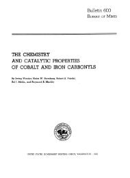
Condition <strong>of</strong> piles:The pattern and amount <strong>of</strong> corrosion on the twopiles were about the same. <strong>Corrosion</strong> was conf<strong>in</strong>edto two areas. One area extended from the top <strong>of</strong> thepiles, which was above ground level, and extendedthrough the zone exposed to the c<strong>in</strong>der and slag fill<strong>in</strong> the water table zone. The other corroded areaoccurred between elevations —115 to —118 ft wherethe piles passed through a sand and gravel bed.Pile II-S was cleaned by sandblast<strong>in</strong>g prior toexam<strong>in</strong>ation, and pile I-S was cleaned with scrapersand wire brushes. Except as noted otherwise, thecorrosion measurements reported are the maximumobserved on the two piles.+ 13 to +8 ft: Slight uniform corrosion and isolated pitt<strong>in</strong>g. Maximum depth <strong>of</strong> pitt<strong>in</strong>g, 35 mils.At least 50 percent <strong>of</strong> the mill scale was <strong>in</strong>tact.Maximum reduction <strong>in</strong> flange thickness, 3 percent.+ 8 to +6: This is the zone show<strong>in</strong>g the maximumcorrosion on both piles. The water l<strong>in</strong>e was at +7 ftfor pile I-S, and at +6.4 ft for pile II-S. The millscale was practically entirely removed; uniform corrosion and many pits were present. Most <strong>of</strong> thepitt<strong>in</strong>g occurred with<strong>in</strong> the 1-ft area above and belowthe water l<strong>in</strong>e. The two maximum pit depths measured on pile I-S were 112 and 90 mils, a few pits werefound between 60 and 75 mils, and other pits lessthen 60 mils <strong>in</strong> depth. On pile II-S, there were 10pits between 55 and 72 mils <strong>in</strong> depth and other pitsless than 50 mils <strong>in</strong> depth. The flange surfaces weremore severely attacked than the web surfaces.Measurements made on the flange with<strong>in</strong> 1-ft <strong>of</strong>the water l<strong>in</strong>e showed that the orig<strong>in</strong>al cross section<strong>of</strong> pile I-S was reduced by an average <strong>of</strong> 29 percent.For pile II-S, the average reduction was 14 percent.The reduction <strong>in</strong> pile thickness due to corrosiontapered <strong>of</strong>f rapidly as the distance away from thewater l<strong>in</strong>e was <strong>in</strong>creased. The average reduction<strong>in</strong> flange cross section on the zone between 1 ft and2 ft below and above the water l<strong>in</strong>e was 2 to 3percent. No perceptible reduction <strong>in</strong> flange thickness was noted 4 ft above or below the water l<strong>in</strong>e.+ 6 to —4: Mill scale <strong>in</strong>tact over 90 percent <strong>of</strong> thepile surfaces. Negligible metal attack and localized pits which were less than 20 mils <strong>in</strong> depth,except for a few pits between 20 and 31 mils.—4 to —11: Slight metal attack <strong>in</strong> a 4-<strong>in</strong>. 2 areawith a maximum pit depth <strong>of</strong> 18 mils on pile II-Sonly. Mill scale <strong>in</strong>tact over 95 percent <strong>of</strong> surface.— 11 to —115: No measurable pit depths. Millscale <strong>in</strong>tact over 95 percent <strong>of</strong> surface.— 115 to —118: At this depth the piles passedthrough a sand and gravel stratum. The steelsurfaces were uniformly corroded and conta<strong>in</strong>edmany localized pits which generally ranged <strong>in</strong> depthup to 50 mils; 12 pits measured between 50 and 65mils and 2 pits had depths <strong>of</strong> 80 and 95 mils. Theaverage reduction <strong>in</strong> flange thickness measured 9and 4 percent, respectively, for pile I-S and forpile II-S.—118 to —126: Practically unaffected by corrosion. Mill scale more than 95 percent <strong>in</strong>tact.Figure 1 shows the condition <strong>of</strong> pile II-S at threedifferent levels.c. Corps <strong>of</strong> Eng<strong>in</strong>eers, Dam and Lock No. 8, Ouachita River,ArkansasHistory:An end pile was pulled from the upstream abutment wall <strong>of</strong> the Corps <strong>of</strong> Eng<strong>in</strong>eers, Dam and LockNo. S on the Ouachita River near El Dorado, Ark.FIGURE 1. Sections <strong>of</strong> the 139-ft H-piles pulled from Sparrows Po<strong>in</strong>t, Maryland, after exposure for 18 years.Left, water table zone consist<strong>in</strong>g <strong>of</strong> fill material; center, clay soil stratum at about elevation —30 ft; and right, coarse sand and gravel stratum underla<strong>in</strong> by claybetween elevations —110 and —126 ft. The pile was cleaned by sandblast<strong>in</strong>g. Note the excellent condition <strong>of</strong> the butt weld at the splice <strong>in</strong> the center photograph.
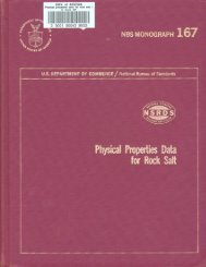
The pile was a shallow-arch sheet pile hav<strong>in</strong>g a 15-<strong>in</strong>.driv<strong>in</strong>g width, and a web thickness which variedfrom 0.45 <strong>in</strong>. at the center to 0.67 <strong>in</strong>. near the edges.The length <strong>of</strong> the pile was 15 ft, the top 2 ft <strong>of</strong> whichwas embedded <strong>in</strong> a concrete cap.Date pile driven: 1921Date pile putted: June 1961Age oj pil<strong>in</strong>g: 40 yearsPil<strong>in</strong>g exposed: Elevation 67.5 to 52.5 ft. Groundl<strong>in</strong>e at elevation 78.5 ft; water l<strong>in</strong>e at 76.5 ft. Thetop <strong>of</strong> the pile was encased <strong>in</strong> concrete to elevation65.5 ft.Soil characteristics:78.5 to 76.5 ft: Silty clay fill with some organicmaterial.76.5 to 64.5:cent sand.64.5 to 60.5:percent sand.Blue clay conta<strong>in</strong><strong>in</strong>g about 40 per-Stiff blue clay conta<strong>in</strong><strong>in</strong>g about 1060.5 to 52.5: Very stiff blue clay conta<strong>in</strong><strong>in</strong>g about2 to 3 percent sand.Soil resistivity and pHElevationResistivitypHft78.5 (Surface).-.-65.5__. _ _ ._..__60.0. . ._.____.___55.0Ohm-cm2,900 (Shepard Canes) __________3,200 (Laboratory) ______________1,540 (Laboratory) _________ ___1,540 (Laboratory) ___ _ _ _4. 36. 24. 6Condition <strong>of</strong> pileThe entire length <strong>of</strong> the pile was driven below thewater table. <strong>Corrosion</strong> was conf<strong>in</strong>ed to a 2-ft section on the river side <strong>of</strong> the pile between elevation59.8 to 61.8 ft. Pitt<strong>in</strong>g occurred <strong>in</strong> 11 places,each about 1 <strong>in</strong>. 2 <strong>in</strong> area, along the f<strong>in</strong>gers <strong>of</strong> the pile.The maximum pit depth was 26 mils and othersranged up to 22 mils. Several pits hav<strong>in</strong>g a maximum depth <strong>of</strong> 20 mils were found <strong>in</strong> a 3-<strong>in</strong> 2 . area <strong>in</strong>the center <strong>of</strong> the web. N<strong>in</strong>ety percent <strong>of</strong> the millscale was <strong>in</strong>tact <strong>in</strong> this moderately corroded zone.At least 95 percent <strong>of</strong> the orig<strong>in</strong>al mill scale wasfound to be <strong>in</strong>tact on the rema<strong>in</strong><strong>in</strong>g areas <strong>of</strong> the pile,and no measurable pits or corrosion beyond the millscale was observed. Based on the maximum pitdepth, the total loss <strong>of</strong> pile thickness <strong>in</strong> the corroded zone could not exceed 5 percent <strong>of</strong> the orig<strong>in</strong>alpile thickness.The portion <strong>of</strong> the pile which conta<strong>in</strong>s the measurable pits is shown <strong>in</strong> figure 2.d. Grenada Dam Spillway, Grenada, MississippiHistory:A type A sheet pile was pulled for exam<strong>in</strong>ationfrom the end <strong>of</strong> the north upstream w<strong>in</strong>gwall <strong>of</strong> theGrenada Dam Spillway at Grenada, Miss. The pilewas 14 ft <strong>in</strong> length, had a driv<strong>in</strong>g width <strong>of</strong> 19}£ <strong>in</strong>.and a thickness <strong>of</strong> % <strong>in</strong>.Date pile driven: October 1948Date pile pulled: July 1960FIGURE 2. Sandblasted 3-ft sectionfrom the 40-year-old pil<strong>in</strong>g extractedfrom an abutment wall <strong>in</strong> the Corps <strong>of</strong>Eng<strong>in</strong>eers Dam and Lock No. 8 onthe Ouachita River near El Dorado,Arkansas.The section was exposed about 18 It belowthe ground l<strong>in</strong>e and it is the only portion <strong>of</strong> thepile which conta<strong>in</strong>ed pits <strong>of</strong> measureable depth.The maximum pit was 26 mils <strong>in</strong> depth.Age <strong>of</strong> pil<strong>in</strong>g: 12 yearsPil<strong>in</strong>g exposed: Elevation 251.5 ft to 237.5 ft; groundelevation at 256 ft, water table much below thebottom <strong>of</strong> pile.Soil characteristics:256.0 to 250.5 ft: Kill soil, reddish brown sandyloam.Elevationft256 to 246. „____._256 to 236________256 to 226__ _____256. .250245.5____________241______________Soil resistivity and pHResistivityOhm-cmM<strong>in</strong> 11,700 (4-p<strong>in</strong>)---------_-Max 15,400 (4-p<strong>in</strong>) _ _ ____ __Avg 13,900 (4-p<strong>in</strong>).. _ __-____.M<strong>in</strong> 4,600 (4-p<strong>in</strong>) -__.__. _____Max 9,600 (4-p<strong>in</strong>) ____________Avg 6,900 (4-p<strong>in</strong>)_______--___M<strong>in</strong> 4,300 (4-p<strong>in</strong>) ___Max 7,300 (4-p<strong>in</strong>) ______ _ __Avg 6,200 (4-p<strong>in</strong>)__._ _______2,800 (Shepard Canes) __> 4,000 (Laboratory). _____> 4,000 (Laboratory) _______3,800 (Laboratory) __ ___PH4 94 93. 6657852—62-
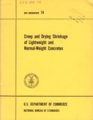
FIGURE 3. Sections (1.5 ft by 1 ft) cut from a pil<strong>in</strong>g which was pulled from the north upstreamw<strong>in</strong>gwall <strong>of</strong> the Grenada Dam Spillway at Grenada, Mississippi, after exposure for 12 years.Sections were cleaned by sandblast<strong>in</strong>g.D103A, section <strong>of</strong> pile exposed to fill soil.D103B, section <strong>of</strong> pile exposed to natural soil.250.5 to 246.6: Fill soil, tan silty sand.246.5 to 244.5: Natural soil layer, grayish bluefractured shale.244.5 to 237.5: Transition from light brown togray clay. Gravel and dark gray shale <strong>in</strong>term<strong>in</strong>gledthroughout horizon. Many f<strong>in</strong>e roots present.Condition <strong>of</strong> pile:251.5 to 246.0 ft: Many scattered pits up to 50mils <strong>in</strong> depth. Seven pits measured between 68 and80 mils, and two pits 88 and 122 mils <strong>in</strong> depth.Pits were <strong>of</strong> similar depth on both sides <strong>of</strong> the pile,but much less numerous on the side fac<strong>in</strong>g thespillway. About 50 percent <strong>of</strong> the mill scale was<strong>in</strong>tact on the spillway side and 10 percent on theother side. The reduction <strong>in</strong> cross section <strong>of</strong> thethree most corroded areas measured between 6 to 8percent <strong>of</strong> the orig<strong>in</strong>al wall thickness.246.0 to 244.0: No measureable pits beyond thethickness <strong>of</strong> the mill scale (8 mils) were found <strong>in</strong> thiszone. About 50 percent <strong>of</strong> the mill scale was <strong>in</strong>tact<strong>in</strong> this area.244.0 to 237.5: About 75 percent <strong>of</strong> the mill scalewas present over the surfaces <strong>in</strong> this zone. Nomeasurable pits were found except two at elevation241.0 ft which were 13 mils <strong>in</strong> depth. The averagewall thickness <strong>of</strong> a 17 X 22 <strong>in</strong>. section removed fromthis zone was 0.37 <strong>in</strong>. after clean<strong>in</strong>g by sandblast<strong>in</strong>g.Sections <strong>of</strong> the pile which were exposed to the filland natural soils are shown <strong>in</strong> figure 3.e. Sardis Dam Outlet, Sardis, MississippiHistory:A 3.5 ft length <strong>of</strong> steel sheet pil<strong>in</strong>g was cut from alength <strong>of</strong> pile pulled from the Sardis Dam Outletchannel on the Little Tallahatchie River near Sardis,Miss. The arch-type pile had a driv<strong>in</strong>g width <strong>of</strong>19% x<strong>in</strong>. and a wall thickness <strong>of</strong> % <strong>in</strong>.Date pile driven: Early 1939Date pile pulled: October 1959Age <strong>of</strong> pil<strong>in</strong>g: 20.5 yearsPil<strong>in</strong>g exposed: Elevation 190.5 to 187 ftSurface elevation: 194.5 ftWater table elevation: Above 194.5 ft.Soil characteristics:194.5 to 190.5 ft: Riprap fill.190.5 to 189.5: Gravel bed.189.5 to 187: Black lignitic clay with layers <strong>of</strong>sand.Elevationft190187—. ----------Soil resistivity and pHResistivityOhm-cm610 (Laboratory). ______ __. _1,690 (Laboratory) _____ _ _____pH8 0? 9
Condition <strong>of</strong> piles:Metal attack occurred <strong>in</strong> the form <strong>of</strong> uniformcorrosion and general pitt<strong>in</strong>g over most <strong>of</strong> the surface. The section exposed to the gravel bed aboveelevation 189.5 ft showed a 19 percent reduction <strong>in</strong>cross section, and maximum depth <strong>of</strong> pitt<strong>in</strong>g up to60 mils. The average thickness <strong>of</strong> the pile sectionexposed to lignitic clay below elevation 189.5 ft wasreduced by 11 percent; the pit depths ranged up to30 mils.f. Chef Menteur Pass, New Orleans, LouisianaHistory:In connection with construction work on theSimpson-Long Bridge across Chef Menteur Pass onU.S. Highway 90, about 11 miles west <strong>of</strong> NewOrleans, it was necessary to pull about 60 tons <strong>of</strong>sheet steel pil<strong>in</strong>gs. The pil<strong>in</strong>gs formed a reta<strong>in</strong><strong>in</strong>gwall for the abutment <strong>of</strong> the bridge. The sheet pileswere 33 ft <strong>in</strong> length, arch type with a driv<strong>in</strong>g width<strong>of</strong> 19% <strong>in</strong>., and a thickness <strong>of</strong> % <strong>in</strong>. at the center <strong>of</strong>the web.Date piles driven: 1929Date piles pulled: 1961Age <strong>of</strong> pil<strong>in</strong>g: 32 yearsPil<strong>in</strong>g exposed: +6 to —27 ft; Water side, +6 to+3± 1 ft <strong>in</strong> atmosphere; +3± 1 ft to 0 ft (mud l<strong>in</strong>e)<strong>in</strong> brackish salt water. Soil side, + 6 to +4 ft <strong>in</strong>atmosphere; ground l<strong>in</strong>e at +4 ft.Soil characteristics:+4 to —4 ft: Light gray loose silty sand,—4 to —27: Very tight gray clay.Elevationft-3_. _-_-_-__---_-10.. __________-24_, ___________Soil resistivity and pHResistivityOhm-cm440 (Laboratory) _._ _ .._____ _.300 (Laboratory) __ ___ _ ______330 (Laboratory) ___ __ _ _._ __pR7. 86. 97.4Condition oj piles:Detailed exam<strong>in</strong>ation <strong>of</strong> four lengths <strong>of</strong> pil<strong>in</strong>gsshowed that the degree and pattern <strong>of</strong> corrosionwere similar. The condition <strong>of</strong> the pile exhibit<strong>in</strong>gthe maximum amount <strong>of</strong> corrosion is reported herewith. Both sides <strong>of</strong> the top 4 ft sections <strong>of</strong> the pileswere coated with a protective alum<strong>in</strong>um-type pa<strong>in</strong>tand an undercoat <strong>of</strong> red lead.Water side:+ 6 to +4 ft: Pa<strong>in</strong>t was <strong>in</strong>tact, unaffected bycorrosion.+4 to +2: Rust and slight metal attack, two pitsmeasured 23 and 38 mils <strong>in</strong> depth, other pits about10 mils.+2 to 0: Thick crust <strong>of</strong> corrosion products onthe f<strong>in</strong>ger <strong>in</strong>terlock edge between 25 and 40 milsthick, localized pitt<strong>in</strong>g and metal attack beneaththe crust, some pits between 40 and 50 mils <strong>in</strong> depth.Th<strong>in</strong> layer <strong>of</strong> corrosion products on flanges, weband thumb <strong>in</strong>terlock with pitt<strong>in</strong>g less than 10 mils<strong>in</strong> depth, except for a few pits between 25 and 60 milson one side <strong>of</strong> the flange at 1 ft. Mill scale almostcompletely removed from this zone.0 to —1: Metal attack and slight pitt<strong>in</strong>g (lessthan 10 mils) on <strong>in</strong>terlock only.— 1 to —14: Mill scale <strong>in</strong>tact over 95 percent<strong>of</strong> surface. Flanges and webs unaffected by corrosion. Slight metal attack and three scattered pits(maximum depth, 70 mils) on f<strong>in</strong>ger <strong>in</strong>terlock at-11 to -12 ft.— 14 to —17: Metal attack and 0 pits rang<strong>in</strong>g <strong>in</strong>depth between 60 to 145 mils along f<strong>in</strong>ger <strong>in</strong>terlock.Two pits (65 and 70 mils) on thumb <strong>in</strong>terlock. Nomeasureable pits on web or flange. Mill scale <strong>in</strong>tactover 80 percent <strong>of</strong> surface.— 17 to —19: Slight metal attack, mill scale<strong>in</strong>tact over 80 percent <strong>of</strong> surface.— 19 to —20: Mill scale <strong>in</strong>tact over 75 percent <strong>of</strong>surface. Four pits between 33 and 88 mils <strong>in</strong> depthon the thumb <strong>in</strong>terlock and flange; two pits, 95 and58 mils <strong>in</strong> depth, on other flange.— 20 to —27: Mill scale <strong>in</strong>tact over 90 percent <strong>of</strong>surface. Only two measurable pits, 80 and 104 mils<strong>in</strong> depth, at —26 ft on f<strong>in</strong>ger <strong>in</strong>terlock.Soil side:+ 6 to +4 ft: Uniform th<strong>in</strong> layer <strong>of</strong> rust, nomeasureable pits.+4 to 0: Uniform layer <strong>of</strong> rust and scale oversurface to a thickness <strong>of</strong> 40 mils. No measureablepits.0 to —27: Metal attack <strong>in</strong> many areas. About75 percent <strong>of</strong> surface covered with mill scale. Nomeasurable pits greater than 10 mils except atelevation —24 ft where a few pits were found on thef<strong>in</strong>ger <strong>in</strong>terlock <strong>of</strong> one pile. Maximum pit depth,25 mils.g. Wilm<strong>in</strong>gton Mar<strong>in</strong>e Term<strong>in</strong>al; Christiana River, DelawareHistory:Four hundred arid thirty two uncoated steel<strong>in</strong>terlock<strong>in</strong>g-arch-type piles, with a driv<strong>in</strong>g width<strong>of</strong> 19% <strong>in</strong>. and an average web thickness <strong>of</strong> % <strong>in</strong>.were pulled by the Wilm<strong>in</strong>gton Harbor Commissionfrom a pile jetty which was used as a shor<strong>in</strong>g alongthe banks <strong>of</strong> the Christiana River. The piles werepulled <strong>in</strong> preparation for extension <strong>of</strong> the dock.The piles were 60 and 100 ft <strong>in</strong> length. Each n<strong>in</strong>thpile was driven 100 ft to serve as an anchor. The100 ft piles consisted <strong>of</strong> a 60 ft section welded to a40 ft section.Date piles driven: 1937Date piles pulled: 1960Age <strong>of</strong> pil<strong>in</strong>g: 23 yearsPil<strong>in</strong>g exposed: Elevation +10 to —90 ft for 100 ftlengths; +10 to —50 ft for 60 ft lengths. Riverside, top 10 ft <strong>of</strong> pile exposed to water or atmosphere.Land side, top 4 ft <strong>of</strong> pile exposed to water oratmosphere.9
Soil characteristics:+ 6 to 0 ft: C<strong>in</strong>der fill.+ 2 to +J ! : Water table at low tide. River wateris nonbmekish fresh water. Mean low water at 0ft,0 to 48: S<strong>of</strong>t black organic silt.48 to —86: Black organic silt with some f<strong>in</strong>esand and clay <strong>in</strong>term<strong>in</strong>gled.— 86 to — 88: F<strong>in</strong>e brown silty sand, trace <strong>of</strong> mica.— 88 to —91 : Gray to brown coarse sand and river— 91 lo --II4: Sand HIM! silty sand underla<strong>in</strong> byday.Condition oj piles:Seven full lengths and the <strong>in</strong>terlock edges <strong>of</strong> 70piles were <strong>in</strong>spected. All the piles were <strong>in</strong> excellentcondition from the mud l<strong>in</strong>e (elevation 0 ft where thenatural soil starts) down to the bottom <strong>of</strong> the piles.The piles are to be reused <strong>in</strong>. the new dock structureat the same site.+ 10 to 0 ft: Moderate corrosion on surfacesexposed to water and the atmosphere on the riverside, and to c<strong>in</strong>der fill, water and atmosphere on theland side. Surfaces were uniformily corroded, theorig<strong>in</strong>al thickness <strong>of</strong> the piles be<strong>in</strong>g reduced by anaverage not exceed<strong>in</strong>g 10 percent. Widely scatteredpits present; most <strong>of</strong> the pits had depths less than75 mils, but a few had depths between 75 to 150mils.0 to bottom <strong>of</strong> piles: Accumulation <strong>of</strong> slick clayover most <strong>of</strong> the surface. No measurable pits.Mill scale <strong>in</strong>tact over more than 90 percent <strong>of</strong> thesurfaces.h. Lumber River Near Boardman, North Carol<strong>in</strong>aHistory:The North Carol<strong>in</strong>a State Highway Departmentextracted 120 piles which formed a rectangularshapedc<strong>of</strong>ferdam for a bridge support over theLumber River near Boardman, N.C. The structurewas removed <strong>in</strong> connection with road improvementswhich required replacement <strong>of</strong> the old bridge.The steel piles were 20-ft lengths <strong>of</strong> <strong>in</strong>terlock<strong>in</strong>gI-beams hav<strong>in</strong>g a driv<strong>in</strong>g width <strong>of</strong> 8 <strong>in</strong>. and a wallthickness <strong>of</strong> 0.25 <strong>in</strong>. The corners <strong>of</strong> the c<strong>of</strong>ferdamconsisted <strong>of</strong> steel angles to which <strong>in</strong>terlock sections<strong>of</strong> pil<strong>in</strong>gs were attached bjr steel rivets, spaced 9 <strong>in</strong>.apart.Date piles driven: 1921Date piles pulled: December 1958Age <strong>of</strong> pil<strong>in</strong>g: 37 yearsPil<strong>in</strong>g exposed: 2.5 ft above ground to 17.5 ft belowthe ground l<strong>in</strong>e ( + 2.5 to —17.5 ft). The portion <strong>of</strong>the piles above the ground l<strong>in</strong>e was subjected topartial or total immersion from water <strong>of</strong> the LumberRiver about 50 percent <strong>of</strong> the year, and to theatmosphere when the river was dry dur<strong>in</strong>g therema<strong>in</strong><strong>in</strong>g half year. The sides <strong>of</strong> the pil<strong>in</strong>gs whichwere exposed to the excavated side <strong>of</strong> the c<strong>of</strong>ferdamwere <strong>in</strong> contact with concrete, except fort he bottom3 ft which was entirely surrounded by soil.10Soil characteristics:0 (ground l<strong>in</strong>e) to —8 ft: Gray f<strong>in</strong>e sandy loam,— 8 to —14: Bluish-gray plastic silty clay.— 14 to —17.5: Gray-black f<strong>in</strong>e sandy loam conta<strong>in</strong><strong>in</strong>g appreciable gravel.3--...10.. ..ElevationftSoil resistivity and pHResistivityOhm-cm1,2401, 1004, 900pE3. 42.35. 9Condition oj piles:Visual <strong>in</strong>spection <strong>of</strong> the pil<strong>in</strong>gs revealed that theyhad all corroded to about the same extent. Asection <strong>of</strong> the c<strong>of</strong>ferdam consist<strong>in</strong>g <strong>of</strong> two fulllengths <strong>of</strong> piles and a corner angle was shipped tothe laboratory for further exam<strong>in</strong>ation.Practically no mill scale rema<strong>in</strong>ed on the pilesurfaces <strong>in</strong> the zone extend<strong>in</strong>g from 3 ft below theground l<strong>in</strong>e to the top <strong>of</strong> the piles. In the lower zones,approximately 20 percent <strong>of</strong> the mill scale was<strong>in</strong>tact.Th<strong>in</strong> concrete deposits were found on the surfaceswhere the steel had been <strong>in</strong> contact with concreteon the excavated side <strong>of</strong> the c<strong>of</strong>ferdam. There wasa thick scale <strong>of</strong> rusted corrosion products and soilover the entire surface exposed directly to the soilenvironments. The scale was flakey and easilyremoved by scrap<strong>in</strong>g.The follow<strong>in</strong>g conditions were observed afterthe piles were cleaned by sandblast<strong>in</strong>g:+ 2.5 to 0 ft: Section exposed to total or partialwater immersion, or atmosphere. Uniform corrosion<strong>of</strong> surface. Measurements <strong>of</strong> the cross section <strong>in</strong>the top 6 <strong>in</strong>. <strong>of</strong> the piles (elevation +2.5 to +2.0)showed a m<strong>in</strong>imum thickness <strong>of</strong> 0.06 <strong>in</strong>. <strong>in</strong> places.This represents a loss <strong>of</strong> 76 percent <strong>in</strong> the orig<strong>in</strong>alpile thickness. The maximum thickness measuredon uncorrpded surfaces near the bottom <strong>of</strong> the pileswas 0.26 <strong>in</strong>. Piles <strong>in</strong> the zone between +2.0 ft tothe ground l<strong>in</strong>e showed a maximum reduction <strong>in</strong>thickness <strong>of</strong> 60 percent.0 to —0.5: This area showed an amount <strong>of</strong> corrosion similar to that on the adjacent areas above.The orig<strong>in</strong>al pile thickness <strong>in</strong> this zone was reducedby a maximum <strong>of</strong> 40 percent, and isolated pits ranged<strong>in</strong> depth up to 60 mils.— 0.5 to —1.0: The pattern <strong>of</strong> corrosion <strong>in</strong> thiszone was similar to that noted above. Maximumreduction <strong>in</strong> pile thickness was 36 percent.— 1.0 to —3.0: Uniform corrosion, general roughen<strong>in</strong>g <strong>of</strong> surface, numerous shallow pits and manyisolated pits up to 60 mils. Maximum reduction <strong>in</strong>cross section was 28 percent.— 3 to —17.5: In this zone the condition <strong>of</strong> thesurface was similar to that described above, but wasless severely corroded. Many isolated pits measuredup to 30 mils <strong>in</strong> depth, and relatively few up to 60
mils. A maximum reduction <strong>in</strong> pile cross section <strong>of</strong>12 percent was noted <strong>in</strong> this zone.The corner angle along the entire pil<strong>in</strong>g sectionshowed the same extent <strong>of</strong> corrosion as the I-beams,All rivets were uniformly corroded. The orig<strong>in</strong>alcontour <strong>of</strong> the rivets was <strong>in</strong>tact.A 3-ft corner section <strong>of</strong> the pil<strong>in</strong>g exposed immediately below the soil l<strong>in</strong>e is shown <strong>in</strong> figure 4.4.2. <strong>Pil<strong>in</strong>gs</strong> Exposed <strong>in</strong> Excavationsa. Memphis Floodwall, Memphis, TennesseeHistory:Excavations were made to expose pil<strong>in</strong>gs at twolocations on the river side <strong>of</strong> the Memphis Floodwall.The walls consist <strong>of</strong> type Z 27 sheet pil<strong>in</strong>gs hav<strong>in</strong>gan 18-<strong>in</strong>. driv<strong>in</strong>g width, and a thickness <strong>of</strong> %-<strong>in</strong>. atthe web and flanges. The pil<strong>in</strong>gs at station 56+14were given two coats <strong>of</strong> cold applied coal-tar-baseenamel before driv<strong>in</strong>g, and the pil<strong>in</strong>gs at station60+00 were uncoated.Date piles driven: November 1953Date <strong>of</strong> <strong>in</strong>spection: March 1960Age <strong>of</strong> pil<strong>in</strong>g: 6.3 yearsCondition <strong>of</strong> piles:The coal tar coat<strong>in</strong>g was <strong>in</strong>tact over the entiresurface except at elevation 220.5 to 219.5 ft wherethe coat<strong>in</strong>g was damaged <strong>in</strong> an area 1-ft <strong>in</strong> verticaldirection by 1-<strong>in</strong>. <strong>in</strong> width. The maximum depth <strong>of</strong>pitt<strong>in</strong>g <strong>of</strong> the steel exposed by the damaged coat<strong>in</strong>gwas 35 mils (fig. 5). The steel beneath the rest <strong>of</strong>the coat<strong>in</strong>g was unaffected by corrosion and the millscale was <strong>in</strong>tact.STATION 60+00Pil<strong>in</strong>g exposed: An 8-ft width <strong>of</strong> the floodwall wasexposed between elevation 222.5 and 213.5 ft.Surface elevation: 226.5 ftWater table elevation: Below 213.5 ftSoil characteristics:226.5 to 224 ft: Brown lean clay.224 to 222.5: Gray silty clay.222.5 to 218.5: Friable brown silty clay. Somec<strong>in</strong>ders mixed with the clay between 223 and 220 ft.218.5 to 213.5: Friable and plastic reddish brownsilty clay. Very impervious to water.STATION 56+14Pil<strong>in</strong>g exposed: An 8-ft width <strong>of</strong> the floodwall wasexposed between elevation 223.0 to 216.5 ft.Surface elevation: 228 ftWater table elevation: 217.5 ftSoil characteristics:228 to 223 ft: Friable brown lean clay.223 to 221.5: Plastic and friable gray silty clay.221.5 to 217.5: Plastic light brown clayey silt.Excessive water below 219.5 ft.217.5 to 216.5: Tight gray clay mixed with decomposed wood.Elevationft228 to 218______-_228 to 208—,-----228 to 198-.-----223— -----------222______________221______________221______________219.5------------219._______--__-_218-—---, ------216.5____________Soil resistivity and pHResistivityOhm-cmM<strong>in</strong> 1,220 (4-p<strong>in</strong>). -----------Max 8,600 (4-p<strong>in</strong>) _-__..______Avg 4,400 (4-p<strong>in</strong>) ___ _____ _M<strong>in</strong> 960 (4-p<strong>in</strong>). _____.__-_Max 6,900 (4-p<strong>in</strong>) ___________Avg 2,600 (4-p<strong>in</strong>). ___________M<strong>in</strong> 1,030 (4-p<strong>in</strong>)____________Max 3,400 ( 4-p<strong>in</strong>) ___ _________Avg 1,850 (4-p<strong>in</strong>)___ ________1,900 (Shepard Canes) _ _ _3,100 (Shepard Canes) _ _2,240 (Laboratory) ______2,300 (Shepard Canes) ___1,700 (Shepard Canes) _ _1,410 (Laboratory) _2,200 (Shepard Canes) __1,000 (Shepard Canes) _ _ _pH7. 87. 611Elevationft226.5 to 216.5___.226.5 to 206.5___._.226.5 to 196.5___._222.. _____________221______________221... .. __________219.5- --_.-_--_-_218.5217__-___________214.._. -._______-213.5-... ________Soil resistivity and pHResistivityOhm- cmM<strong>in</strong> 2, 1 80 (4-p<strong>in</strong>) _ _ __________Max 5,700 (4-p<strong>in</strong>) ____.__.._ .. _Avg 4,100 (4-p<strong>in</strong>)... _______.._M<strong>in</strong> 1,920 (4-p<strong>in</strong>) _____________Max 7,900 (4-p<strong>in</strong>) ____________Avg 4,200 (4-p<strong>in</strong>) ____________M<strong>in</strong> 1,030 (4-p<strong>in</strong>) __ __._Max 2,300 (4-pm)_______.-.__Avg 1,650 (4~p<strong>in</strong>)____________3,200 (Shepard Canes) ___2,500 (Shepard Canes). __2,200 (Laboratory) _______2,600 (Shepard Canes) _ _ .2, 100 (Shepard Canes) _ _ _1,690 (Laboratory) _______1,630 (Laboratory) _______1,500 (Shepard Canes)___pH6. 87. 87.5Condition <strong>of</strong> piles:The entire surface <strong>of</strong> the pil<strong>in</strong>gs was <strong>in</strong> excellentcondition. More than 90 percent <strong>of</strong> the mill scalewas <strong>in</strong>tact. There was very slight uniform metalattack <strong>in</strong> small localized areas. No measurable pitswere found on the entire surface. From elevation218 to the bottom <strong>of</strong> the excavated pit, the clayadhered very tightly to the pil<strong>in</strong>g. On removal,the soil peeled <strong>of</strong>f <strong>in</strong> layers leav<strong>in</strong>g free water on thesteel surface.A 2 ft by 1 ft section removed from the pile isannti^^n <strong>in</strong> •RnciiTo £.
FIGURE 4. A S-ft section <strong>of</strong> steel sheetpil<strong>in</strong>g exposed below the soil l<strong>in</strong>e <strong>in</strong>a c<strong>of</strong>ferdam structure <strong>in</strong> the LumberRiver near Boardman, North Carol<strong>in</strong>a.Exposure, 37 years.FIGURE 5. <strong>Steel</strong> sheet pil<strong>in</strong>g sections (d ft by 1 ft) cut from twolocations on the Memphis Floodwall after exposure for 6.3years.The sections were cleaned by sandblast<strong>in</strong>g.A101, section <strong>of</strong> coated pil<strong>in</strong>g show<strong>in</strong>g pits up to 35 mils <strong>in</strong> depth, occurr<strong>in</strong>g <strong>in</strong>area <strong>of</strong> damaged coat<strong>in</strong>g.A102, section <strong>of</strong> uncoated pil<strong>in</strong>g exposed to a silty clay conta<strong>in</strong><strong>in</strong>g c<strong>in</strong>dersshow<strong>in</strong>g no measureable corrosion.b. Vicksburg Floodwall, Vicksburg, MississippiHistory:Excavations were made to expose steel sheetpil<strong>in</strong>gs at two locations on the riverside <strong>of</strong> theVicksburg Floodwall. The walls were constructed<strong>of</strong> type Z 38 sheet pil<strong>in</strong>g which has a driv<strong>in</strong>g width<strong>of</strong> 18 <strong>in</strong>., a thickness <strong>of</strong> % <strong>in</strong>. at the web, and a thickness <strong>of</strong> Yz <strong>in</strong>. at the flanges.Date piles driven: January 1953Date oj <strong>in</strong>spection: March 1960Age oj pil<strong>in</strong>g: 7.2 yearsSTATION 16+32Pil<strong>in</strong>g exposed: A 38-<strong>in</strong>. width <strong>of</strong> the floodwall wasexposed between elevation 89 and 80.5 ft.Surface elevation: 93 ftWater table elevation: 80.5 ftSoil characteristics:93 to 86 ft: Bluish black fat clay, sticky, plastic,and very retentive <strong>of</strong> water. Small patches <strong>of</strong> redand yellow sand dispersed throughout the pr<strong>of</strong>ile.86.0 to 85.5: Black silty plastic clay, conta<strong>in</strong><strong>in</strong>gmore than 50 percent c<strong>in</strong>ders.85.5 to 84.5: Light brown sandy loam with c<strong>in</strong>dersand gravel dispersed throughout.84.5 to 84.0: Layer <strong>of</strong> black c<strong>in</strong>ders.84.0 to 80.5: Gray sandy silt conta<strong>in</strong><strong>in</strong>g c<strong>in</strong>ders.Wet c<strong>in</strong>ders on floor <strong>of</strong> excavation at 80.5 ft.12Elevation93 to83_— __ — _93 to 73_____----_93 to 63—_ ___--_88-. ------------88 to 87... — . — —85— — --------83—— — — — —82.5_.__ ——— ——82 to 80_. --------80.5-- — ———— -Soil resistivity and pHM<strong>in</strong>MaxAvgM<strong>in</strong>MaxAvgM<strong>in</strong>MaxAvgM<strong>in</strong>MaxM<strong>in</strong>MaxM<strong>in</strong>MaxM<strong>in</strong>MaxResistivityOhm-cm3,400 (4-p<strong>in</strong>). ___________7,000 (4-p<strong>in</strong>) — .. ——— __6,000 (4-p<strong>in</strong>)... .._._.___2,200 (4-p<strong>in</strong>)____________4,300 (4-p<strong>in</strong>). ___________3,300 (4-p<strong>in</strong>) __ _-______-920 (4-p<strong>in</strong>).. — — — — ..2,400 (4-p<strong>in</strong>) ——— _ —— __1,550 (4-p<strong>in</strong>). _____-__--_1,190 (Laboratory) ______850 (Shepard Canes) _ . .1,300 (Shepard Canes) __.1,700 (Shepard Canes) _ . _2,500 (Shepard Canes) _ _ _2,500 (Laboratory) ...___1,750 (Laboratory) _ , „ _ _1,550 (Shepard Canes)4,000 (Shepard Canes) ...850 (Shepard Canes)1,400 (Shepard Canes) _ _ .pH7. 47.68. 2
ElevationSoil resistivity and pHResistivitypRFIGURE 6. Sandblasted sections <strong>of</strong> Z-type sheet pil<strong>in</strong>g cut fromtwo different locations <strong>in</strong> the Vicksbunj Floodwall afterexposure for 7 years.Although c<strong>in</strong>ders were present <strong>in</strong> the soil at both locations, no significant corrosion occurred.B101, Section removed from floodwall at station 16+32.B102, Section removed from floodwall at station 23+83.Condition <strong>of</strong> piles:Approximately 30 to 40 pel-cent <strong>of</strong> the steel surfaceswas covered with mill scale. Soil adhered <strong>in</strong> manyareas <strong>of</strong> about 1-<strong>in</strong>. 2 like barnacles, beneath whichappeared uniform metal attack or shallow pitt<strong>in</strong>g.Pitt<strong>in</strong>g up to 40 mils <strong>in</strong> depth was widely scatteredand conf<strong>in</strong>ed to areas <strong>of</strong> less than 1 <strong>in</strong>. 2 At elevation83.5 to 81.5 ft, there were a few pits with depthsbetween 40 and 45 mils. Measurements made onthe three most corroded 1 <strong>in</strong>. 2 areas showed an average reduction <strong>in</strong> the cross section <strong>of</strong> the web <strong>of</strong> 4 to 6percent. A section removed from the most corrodedarea <strong>of</strong> the pile is shown <strong>in</strong> figure 6.STATION 23 + 83Pil<strong>in</strong>g exposed: A 41-<strong>in</strong>. width <strong>of</strong> the flood wall wasexposed between elevation 89 and 80.5 ft.Surface elevation: 93 ftWater table elevation: 80.5 ftSoil characteristics:93 to 84 ft: Bluish-gray clay with nodules <strong>of</strong> brownclay dispersed throughout.84 to 83.5: Plastic and sticky light brown toreddish brown clay conta<strong>in</strong><strong>in</strong>g some c<strong>in</strong>ders.83.5 to 80.5: Dark gray silty sand mixed withappreciable quantities <strong>of</strong> c<strong>in</strong>ders, gravel, stones, andbricks. This horizon appears to be a fill material.Free water at bottom <strong>of</strong> trench.ft93 to 83..- ----___93 to 73 _______93 to 63- _______ .89 to 8488.5_____________83.5. _. ..-__„__-.83_______________81____-__-_______83.5 to80.5_______M<strong>in</strong>MaxAvgM<strong>in</strong>MaxAvgM<strong>in</strong>MaxAvgM<strong>in</strong>MaxAvgM<strong>in</strong>MaxAvgOhm-cm2,800 (4-p<strong>in</strong>)____________9,200 (4-p<strong>in</strong>)._ __________5,000 (4-p<strong>in</strong>)____________1,300 (4-p<strong>in</strong>) ___ _________3,700 (4-p<strong>in</strong>)___ _________2,800 (4-p<strong>in</strong>) ___ _________740 (4-p<strong>in</strong>)____________2,000 (4-p<strong>in</strong>)_____ _______1,400 (4-p<strong>in</strong>).____ _______825 (Shepard Canes) _ _ _725 (Shepard Canes) _ _910 (Laboratory) _ _ _ - _1,700 (Shepard Canes) _ _ _3,900 (Laboratory) ______1,050 (Laboratory) ______1,100 (Shepard Canes) _ _ _1,400 (Shepard Canes) _ _ _1,300 (Shepard Canes) _ . .7. 18. 67. 7Condition <strong>of</strong> piles:Mill scale was <strong>in</strong>tact on about 70 percent <strong>of</strong> thepil<strong>in</strong>g surfaces. There was no difference <strong>in</strong> theappearance <strong>of</strong> the surface at the different horizons.Where the mill scale had been removed, there was afilm <strong>of</strong> red rust which was brushed <strong>of</strong>f with ease.Under the rust, the steel surfaces were smooth. Nomeasureable pits were found on the exposed pil<strong>in</strong>gs.Measurements fail to show a perceptible reduction <strong>in</strong>wall thickness (fig. 6).c. Sardis Dam Spillway, Sardis, MississippiHistory:An excavation was made to expose a 7-ft width<strong>of</strong> pil<strong>in</strong>gs from the upstream w<strong>in</strong>gwall on the eastside <strong>of</strong> the Sardis Dam Spillway. The structureconsisted <strong>of</strong> arch-type sheet piles with a 15-<strong>in</strong>.driv<strong>in</strong>g width and a wall thickness <strong>of</strong> % <strong>in</strong>.Date piles driven: Early 1940Date <strong>of</strong> <strong>in</strong>spection: March 1960Age <strong>of</strong> pil<strong>in</strong>g: 20 yearsPil<strong>in</strong>g exposed: A 7-ft width <strong>of</strong> the w<strong>in</strong>gwall wasexposed from elevation 307 to 302 ft.Surface elevation: 312 ftWater table elevation: 305 ftSoil characteristics:312 to 305 ft: Fill soil consist<strong>in</strong>g <strong>of</strong> uniform reddishsandy loam.305 to 302: Natural soil, reddish brown tightimpervious plastic clay.
Soil resistivity and pHSoil resistivity and pHElevationResistivitypHElevationResistivitypHfl312 to 302-.._._._Ohm-ctnM<strong>in</strong>. 43,600 (4-p<strong>in</strong>) ___.____._.....Max. 50,200 (4-p<strong>in</strong>) _______ _ ____Avg. 46,500 (4-p<strong>in</strong>)........ _.„_„....ft256-246 ________Ohm-cmM<strong>in</strong> 12,500 (4-p<strong>in</strong>) .... — —Max 16,500 (4r-p<strong>in</strong>) ____ — _ —Avg 13,900 (4-p<strong>in</strong>)__ __._.-___U12 to 192_. .-_-.-M<strong>in</strong>. 29,100 (4-p<strong>in</strong>)..... ..____.__..Max. 36,000 (4-p<strong>in</strong>) ......_______„Avg, 32,800 (4-p<strong>in</strong>) .._.____25H-236. _..._.. _M<strong>in</strong> 4,700 (4-p<strong>in</strong>) __. — ___ —Max 9,600 (4-p<strong>in</strong>) _ .„ — — — _Avg 6,900 (4-p<strong>in</strong> )._ _____312 to 182_.----_.M<strong>in</strong>. 23,800 (4-p<strong>in</strong>) .......__...._Max. 29,300 (4-p<strong>in</strong>) ...__.__.______Avg. 26,000 (4-p<strong>in</strong>) ____ ._.____.__256-226. .__.--_._M<strong>in</strong> 4,300 (4-p<strong>in</strong>).. _ __-._._Max 7,200 (4-p<strong>in</strong>) ___ _______.._Avg 6,200 (4-p<strong>in</strong>) _ _____312..............310-. ---_---_---306 _ _303— .--__-_--..-302.......------.302....... .......> 10,000 (Shepard Canes)> 10,000 (Shepard Canes). . _1 5,400 (Laboratory) ____„__> 4,000 (Laboratory) ...._____7,510 (Laboratory)3,000 (Shepard Caries) ______5.76.05. 4255..... — — —— -249__247_-_____-______246______________9,000 (Shepard Canes) ___2,400 (Laboratory) ___ _2,300 (Laboratory) _ _ _ _ _M<strong>in</strong> 1,700 (Shepard Canes). __Max 3,500 (Shepard Canes) _ _ _Avg 2,400 (Shepard Canes) _ _ _4 44 0Condition oj piles:Mill scale was <strong>in</strong>tact over approximately 90 percent <strong>of</strong> the pile surfaces. In localized areas, whichwere predom<strong>in</strong>ant <strong>in</strong> the top 8-iii. section <strong>of</strong> thepiles, there was slight metal attack and shallowpitt<strong>in</strong>g, not exceed<strong>in</strong>g 10 mils <strong>in</strong> depth. In anarea cover<strong>in</strong>g a width <strong>of</strong> about 2 ft between elevation 304 and 302.5 ft, there were isolated pits whichmeasured between 10 and 20 mils <strong>in</strong> depth, andthree pits between 20 and 28 mils. The averagereduction <strong>in</strong> pile thickness measured <strong>in</strong> the threemost corroded areas <strong>in</strong> this zone was between 3 and4 percent.d. Grenada Dam Spillway, Grenada, MississippiHistory:Two excavations were made to expose steel sheetpil<strong>in</strong>gs for exam<strong>in</strong>ation on the north side and thesouth side <strong>of</strong> the upstream w<strong>in</strong>gwalls <strong>of</strong> the GrenadaDam Spillway on the Yalobusha River. The pil<strong>in</strong>gsconsisted <strong>of</strong> the arch-sheet type with a driv<strong>in</strong>g width<strong>of</strong> 15 <strong>in</strong>. and a wall thickness <strong>of</strong> % <strong>in</strong>.Date piles driven: October 1948Date oj <strong>in</strong>spection: March 1960Age oj pil<strong>in</strong>g: 11,4 yearsUPSTREAM WINGWALL—NORTH SIDEPil<strong>in</strong>g exposed: A 6.7 ft width <strong>of</strong> the w<strong>in</strong>gwall wasexposed between elevation 251.5 and 246 ft.Surface elevation: 256 ftWater table elevation: Much below 246 ftSoil characteristics:256 to 246 ft: Fill material consist<strong>in</strong>g <strong>of</strong> friablereddish brown clayey sand or silt loam with clods<strong>of</strong> grayish sandy clay and patches <strong>of</strong> very f<strong>in</strong>e yellowish brown sand throughout the pit. Gravel, stones,pieces <strong>of</strong> dark gray shale, and f<strong>in</strong>e roots present.Condition oj piles:Mill scale was <strong>in</strong>tact on about 20 percent <strong>of</strong> thepile surfaces. Approximately 60 percent <strong>of</strong> the surface was uniformly corroded to shallow depths andconta<strong>in</strong>ed many scattered pits which generallyranged <strong>in</strong> depth between 40 and 90 mils. A fewpits between 90 and 108 mils <strong>in</strong> depth were present.The deepest pits were ma<strong>in</strong>ly concentrated betweenelevation 248 and 247 ft. The deeper pits werehighly localized and were found under nodules <strong>of</strong> soilparticles which appeared to be cemented to the steeland were difficult to scrape away. Measurements <strong>of</strong>the three most corroded areas showed average reductions <strong>in</strong> the thickness <strong>of</strong> the piles <strong>of</strong> 16, 13, and 10percent.UPSTREAM WINGWALL—SOUTH SIDEPil<strong>in</strong>g exposed: A 7-ft width <strong>of</strong> the pil<strong>in</strong>gs <strong>in</strong> thew<strong>in</strong>gwall was exposed between elevation 251.5 and246 ft.Surface elevation: 256 ftWater table elevation: Much below 246 ftSoil characteristics:256 to 248 ft: Reddish brown f<strong>in</strong>e sandy loam withclods <strong>of</strong> light gray clay dispersed throughout thepr<strong>of</strong>ile. This is a fill soil conta<strong>in</strong><strong>in</strong>g many f<strong>in</strong>e roots.248 to 246: Mixture <strong>of</strong> f<strong>in</strong>e rust colored very f<strong>in</strong>elight yellow silty sand <strong>in</strong>term<strong>in</strong>gled with pieces <strong>of</strong>light gray shale.Elevationft256 to 246____-_ _ M<strong>in</strong>MaxAveSoil resistivity and pHResistivityOhm-cm5,900 (4-p<strong>in</strong>) __ ___ _8,000 (4-p<strong>in</strong>).. . .........7,000 (4-p<strong>in</strong>) ___________pH14
Elevationft256 to 236_____ __256 to 226------250248 5247246—— - —— _-„_Soil resistivity and pH — Cont<strong>in</strong>uedM<strong>in</strong>MaxAvgM<strong>in</strong>MaxAvgM<strong>in</strong>MaxAvgResistivityOhm-cm3,400 (4-p<strong>in</strong>) __ __ __6,900 (4-p<strong>in</strong>)_-____ ___ _4,300 (4-p<strong>in</strong>)___________2,700 (4-p<strong>in</strong>)____________3,800 (4-p<strong>in</strong>)____________3,500 (4-p<strong>in</strong>)____________2,400 (Laboratorv) ___ _4,000 (Laboratorv) ______4,300 (Laboratory) _ _ _5,000 (Shepard Canes) _ _ _11,000 (Shepard Canes) __7,900 (Shepard Canes). __pR4 46 46. 9Condition <strong>of</strong> piles:251.5 to 248 ft: Mill scale was present over 70percent <strong>of</strong> the surface. Many highly localized pitscorroded about 15 percent <strong>of</strong> the surface, the rema<strong>in</strong><strong>in</strong>g 85 percent <strong>of</strong> the surface was unaffected bycorrosion. Six pits were found between 100 and 172mils <strong>in</strong> depth, eight pits between 50 and 95 mils, andother pits measured less than 50 mils. The corrosionproducts and soil particles adher<strong>in</strong>g to the steel <strong>in</strong>this zone were easily scraped <strong>of</strong>f.248 to 246: About 30 percent <strong>of</strong> the pil<strong>in</strong>g surfaceswere affected by scattered pits, the other areas be<strong>in</strong>gunaffected by corrosion. Mill scale was <strong>in</strong>tact overmore than 50 percent <strong>of</strong> the surface. The sevendeepest pits ranged between 105 and 160 mils <strong>in</strong>depth. Also present were 11 pits between 50 and 95mils and other pits less than 50 mils <strong>in</strong> depth. Theaverage reduction <strong>in</strong> wall thickness measured <strong>in</strong> thethree most corroded areas was between 12 and 19percent. In this zone, the soil particles were easilyscraped from the steel surfaces, but a black crust <strong>of</strong>ferric oxide which was embedded <strong>in</strong> the pits wasdifficult to break away.e. Berwick Lock, Berwick, LouisianaHistory:Two excavations were made to expose steel pil<strong>in</strong>gs<strong>in</strong> the cut<strong>of</strong>f walls on the west side and east side <strong>of</strong>the north end <strong>of</strong> the Berwick Lock which is locatedbetween the Lower Atchafalaya River and BerwickBay near Berwick, La. The arch-type sheet steelpil<strong>in</strong>gs had a driv<strong>in</strong>g width <strong>of</strong> 19% <strong>in</strong>. and a % <strong>in</strong>.wall thickness.Date piles driven: March 1949Date <strong>of</strong> <strong>in</strong>spection: April 1960Age <strong>of</strong> pil<strong>in</strong>g: 11.1 yearsNORTH END OF LOCK—WEST SIDEPil<strong>in</strong>g exposed: A 5-ft width <strong>of</strong> pil<strong>in</strong>gs was exposedbetween elevation +3.5 to —1.5 ft. One side <strong>of</strong> thepil<strong>in</strong>gs which was uncoated, was totally exposed tothe soil environment. The other side <strong>of</strong> the pil<strong>in</strong>gs15had a coal tar coat<strong>in</strong>g and was exposed to water.Surface elevation: + 5 f tWater table elevation: —0.5 ftSoil characteristics:+ 5 to + 2 ft: Fill material consist<strong>in</strong>g <strong>of</strong> a mixture<strong>of</strong> gray and brown silty clay conta<strong>in</strong><strong>in</strong>g some graveland small shells.+ 2 to —1.5: Natural soil consist<strong>in</strong>g <strong>of</strong> tight bluishgray impervious plastic clay with patches <strong>of</strong> tightbrown clay dispersed throughout the pr<strong>of</strong>ile.Elevationft+ 5 to -5_+ 5 to —15_+ 5 to -25_-1__.0__--1.5-Soil resistivity and pHM<strong>in</strong>MaxAvgResistivityOhm-cm860 (4-p<strong>in</strong>) _.960 (4-p<strong>in</strong>) _.900 (4-p<strong>in</strong>)..M<strong>in</strong> 990 (4-p<strong>in</strong>).Max 1, 260 (4-p<strong>in</strong>).Avg 1, 190 (4-p<strong>in</strong>).M<strong>in</strong> 1, 380 (4-p<strong>in</strong>).Max 1, 550 (4-p<strong>in</strong>).Avg 1, 440 (4-p<strong>in</strong>).M<strong>in</strong> 680 (Shepard Canes),Max 950 (Shepard Canes) _Avg 820 (Shepard Canes).1, 000 (Shepard Canes).1,400 (Laboratory).„__1, 290 (Laboratory) ____850 (Shepard Canes) _800 (Shepard Canes).850 (Shepard Canes) _8. 58. 1Condition <strong>of</strong> piles:+ 3.5 to +1.5 ft: Mill scale was <strong>in</strong>tact over 40percent <strong>of</strong> the surface. The rema<strong>in</strong><strong>in</strong>g surface wasuniformly attacked and had many shallow pits lessthan 25 mils <strong>in</strong> depth, and some deeper pits. Afew pits ranged between 55 and 61 mils <strong>in</strong> depth,and many others ranged between 25 and 55 mils.The average reduction <strong>in</strong> wall thickness observed onthe three most corroded areas was between 6 and 8percent.+1.5 to —1.5 ft: Mill scale was <strong>in</strong>tact over about60 percent <strong>of</strong> the surface. Slight uniform corrosionwas present on the rema<strong>in</strong><strong>in</strong>g surface and there weremany pits which did not exceed 25 mils <strong>in</strong> depth.There was slight general metal attack and pitt<strong>in</strong>gover the entire coated side <strong>of</strong> the pil<strong>in</strong>gs which wasexposed on the water side. The river water had aresistivity <strong>of</strong> 2,500 ohm-cm, and a salt content <strong>of</strong>40 ppm.NORTH END OF LOCK—EAST SIDEPil<strong>in</strong>g exposed: A 5 ft width <strong>of</strong> the wall was exposedbetween elevation +3.5 and 0 ft.Surface elevation: + 5 f tWater table elevation: + 1 f tSoil characteristics:+ 5 to + 3 ft: Fill consist<strong>in</strong>g <strong>of</strong> a mixture <strong>of</strong> slightly
friable reddish brown and gray tight clay conta<strong>in</strong><strong>in</strong>ggrave*] and many stones.+ 3 to 0: Natural soil consist<strong>in</strong>g <strong>of</strong> brown fatplastic clay.Elevationft-f 5 to — 5 _ _ . _ _ M<strong>in</strong>MaxAvg+ 5 to — ];>...._.. M<strong>in</strong>j Max| Avg+ 5 to — 25 _ , _ _ _ M<strong>in</strong>MaxAvg+ 4 _ . _ _ _ M<strong>in</strong>Max-4-15+ ] ______ M<strong>in</strong>Max0_-_---------_--- M<strong>in</strong>| MaxSoil resistivity and pHResistivityOhm-cm960 (4-p<strong>in</strong>) __________1, 280 (4-p<strong>in</strong>) _ ____________1, 130_______--________._1, 150___._____.___. ...__,1, 530___.________________1, 370____________________1, 610__________________1,480.. -___.--___-.____._950 (Shepard Canes) _____1, 300 (Shepard Canes) __. _1, 050 (Laboratory) -_._____1,220 (Laboratory).. ______870 (Shepard Canes) _____] , 000 (Shepard Canes)750 (Shepard Canes)1, 200 (Shepard Caries) _ ___PH8. 17. 9Condition <strong>of</strong> piles:+3 to +1 ft: Mill scale was present on 40 percent<strong>of</strong> nilp snrfn.p.PS Tliprp W*IR uniform r>nrro«<strong>in</strong>nand pitt<strong>in</strong>g where the mill scale was miss<strong>in</strong>g. Thethree deepest pits were between 75 and 90 mils <strong>in</strong>depth. About 30 pits measured between 20 and75 mils <strong>in</strong> depth, and many other pits were shallowerthan 20 mils. The average reduction <strong>in</strong> pile thickness observed <strong>in</strong> the three most corroded areaswas between 8 and 11 percent.+ 1 to 0: About 75 percent <strong>of</strong> the mill scale was<strong>in</strong>tact <strong>in</strong> this zone. The pile surfaces were smooth,had little metal attack, arid all pits were lessthan 20 mils <strong>in</strong> depth.The condition <strong>of</strong> the coated piles exposed to thewater side was similar to that described for thepil<strong>in</strong>g on the west side <strong>of</strong> the lock.f. Algiers Lock, New Orleans, LouisianaHistory:An excavation was made to expose type Z 32 sheetpil<strong>in</strong>gs <strong>in</strong> the cut<strong>of</strong>f wall on the east side <strong>of</strong> thesouth end <strong>of</strong> Algiers Lock, which is located on theAlgiers Canal at the Mississippi Kiver, New Orleans,La. The piles have a driv<strong>in</strong>g width <strong>of</strong> 21 <strong>in</strong>. andwall thicknesses <strong>of</strong> % <strong>in</strong>. at the web and } <strong>in</strong>. at theflanges.Date piles driven: May 1948Date <strong>of</strong> <strong>in</strong>spection: April 1960Age <strong>of</strong> pil<strong>in</strong>g: 11.9 yearsPil<strong>in</strong>g exposed: A 5-ft width <strong>of</strong> the cut<strong>of</strong>f wall wasexposed between elevation +3.5 to +1 ftSurface elevation: +5 ftWater table elevation: +2 ftSoil characteristics:+ 5 to 3.5 ft: Brown silty clay fill material.+3.5 to +1: Brown silty clay with pockets <strong>of</strong>tight plastic grayish blue clay dispersed throughoutthe pr<strong>of</strong>ile with large quantities <strong>of</strong> organic matter,rotted wood, gravel, and small stones.Elevationn+ 5 to —5_._____.+ 5 to -15_______+ 5 to — 25_______+ 5+ 3+ 2+ 1Soil resistivity and pHM<strong>in</strong>MaxAvgM<strong>in</strong>MaxAvgM<strong>in</strong>MaxAvgM<strong>in</strong>MaxM<strong>in</strong>MaxResistivityOhm-cm800 (4-p<strong>in</strong>) _ _ _ _ _ _____840 (4-p<strong>in</strong>)_____________820 (4-p<strong>in</strong>). _____....___575 (4-p<strong>in</strong>) _650 (4-p<strong>in</strong>)_____________600 (4-p<strong>in</strong>)_____________345 (4-p<strong>in</strong>)_____________460 (4-p<strong>in</strong>) _ ______ __410 (4-p<strong>in</strong>)_____________700 (Shepard Canes) _1, 150 (Shepard Canes) _____1, 300 (Shepard Canes)_____1, 140 (Laboratory)1, 290 (Laboratory) _ _650 (Shepard Canes) _1, 200 (Shepard Canes) ___1, 300 (Shepard Canes) ___,H8.47 7Condition <strong>of</strong> piles:Mill scale was present over approximately 85percent <strong>of</strong> the surface. Nodules <strong>of</strong> clay adheredto the steel surface <strong>in</strong> scattered small areas, generally not exceed<strong>in</strong>g 1 <strong>in</strong>. 2 <strong>in</strong> size, beneath which werelight metal attack or pitt<strong>in</strong>g. The deepest pitmeasured 40 mils <strong>in</strong> depth. N<strong>in</strong>e pits measuredbetween 22 and 32 mils <strong>in</strong> depth, and other pitsmeasured less than 20 mils. The average reduction<strong>in</strong> wall thickness measured on the three most corroded areas <strong>of</strong> the sample pile section cut from thewall was between 3 and 4 percent.g. Enid Dam Spillway, Enid, MississippiHistory:An 8-ft width <strong>of</strong> steel sheet pil<strong>in</strong>gs was exposed onthe north side <strong>of</strong> the upstream w<strong>in</strong>gwall <strong>in</strong> the EnidDam Spillway. The piles consisted <strong>of</strong> <strong>in</strong>terlock<strong>in</strong>garch-type beams hav<strong>in</strong>g a driv<strong>in</strong>g width <strong>of</strong> 18 <strong>in</strong>.Date piles driven: September 1949Date <strong>of</strong> <strong>in</strong>spection: May 1961Age <strong>of</strong> pil<strong>in</strong>g: 11.7 yearsPil<strong>in</strong>g exposed: An 8-ft width <strong>of</strong> the pil<strong>in</strong>gs wasexposed between elevation 288 and 282.5 ft.Surface elevation: 293 ftWater table elevation: Much below 282.5 ftSoil characteristics:293 to 290.5 ft: Brown silty clay, somewhatplastic.16
290.5 to 282.5 : Reddish brown coarse sandta<strong>in</strong><strong>in</strong>g much jsilt and gravel.Elevation293__ ............290.5___. ________288_.____________284___. ____..___.282__ _____ _____282.5 ___________Soil resistivity and pHResistivityOhm-cm8,500 (Shepard Canes). __ _____8,000 (Shepard Canes) ___ _10,000 (Shepard Canes) _ _> 4,000 (Laboratorv) ______10,200 (Laboratory). _ _ ...9,500 (Shepard Canes) __ __ __con-?H5. 15.3Condition <strong>of</strong> piles:Mill scale was <strong>in</strong>tact over more than 90 percent<strong>of</strong> the surface. Slight metal attack was present <strong>in</strong>a few small areas, approximately 1 <strong>in</strong>. <strong>in</strong> diameter.There were no measurable pits.5. DiscussionPrevious <strong>in</strong>vestigations on soil corrosion conductedby the National Bureau <strong>of</strong> Standards have beenrestricted to the behavior <strong>of</strong> metals <strong>in</strong> disturbedsoils; trenches or excavations were dug and backfilled after <strong>in</strong>stallation <strong>of</strong> the specimens. Becauseno prior systematic <strong>in</strong>vestigation perta<strong>in</strong><strong>in</strong>g to thebehavior <strong>of</strong> metals <strong>in</strong> undisturbed soils had beenconducted, it became general practice because noother data were available to apply the <strong>in</strong>formationprovided by the NBS soil <strong>in</strong>vestigations as a guideto estimate the corrosion <strong>of</strong> metals <strong>in</strong> all types <strong>of</strong>underground <strong>in</strong>stallations, under both disturbed andundisturbed soil conditions.The f<strong>in</strong>d<strong>in</strong>gs <strong>of</strong> the National Bureau <strong>of</strong> Standardswith respect to the action <strong>of</strong> soils on metals havebeen presented on numerous occasions <strong>in</strong> variousways, and more recently assembled <strong>in</strong> the NationalBureau <strong>of</strong> Standards Circular 579 [1]. The follow<strong>in</strong>g repetition <strong>of</strong> the previously obta<strong>in</strong>ed major conclusions perta<strong>in</strong><strong>in</strong>g to the corrosion <strong>of</strong> iron and steelis not for the purpose <strong>of</strong> impart<strong>in</strong>g new <strong>in</strong>formation,but to establish a basis for discussion <strong>of</strong> the dataobta<strong>in</strong>ed from the pil<strong>in</strong>g <strong>in</strong>spections.Briefly, the Bureau has found, first, that thecorrosion <strong>of</strong> the commonly used ferrous metals is <strong>of</strong>the same type and order <strong>of</strong> magnitude when exposedto a given soil environment; and second, that thecorrosion <strong>of</strong> ferrous metals <strong>in</strong> different soil environments varies widely. In general, <strong>in</strong> well-dra<strong>in</strong>edhigh-resistivity soils, the rate <strong>of</strong> corrosion may behigh <strong>in</strong>itially, but decreases after a few years toalmost complete cessation <strong>of</strong> pitt<strong>in</strong>g. Conversely,<strong>in</strong> poorly dra<strong>in</strong>ed soils hav<strong>in</strong>g low resistivities, therate <strong>of</strong> corrosion is nearly constant with time afterthe <strong>in</strong>itial period.One <strong>of</strong> the most <strong>in</strong>terest<strong>in</strong>g characteristics <strong>of</strong>underground corrosion is the irregular nature <strong>of</strong> theattack. A section <strong>of</strong> pipe is <strong>of</strong>ten penetrated at onlyone or more po<strong>in</strong>ts and practically no corrosion isfound elsewhere on the section. Usually, the loss<strong>of</strong> ferrous metal is too small to be <strong>of</strong> importance ifit were uniformly distributed over a metal surface.The major cause <strong>of</strong> corrosion can be attributed tothe nonuniformity <strong>in</strong> the distribution <strong>of</strong> oxygen andmoisture along the surface <strong>of</strong> a buried metallicstructure. Variations <strong>in</strong> the supply <strong>of</strong> oxygen canset up oxygen-concentration cells <strong>in</strong> which the metalsurfaces which are least accessible to oxygen areanodic to the surfaces to which oxygen is morereadily accessible. The corrosion may be either general or localized depend<strong>in</strong>g upon the relative size <strong>of</strong>the anodic and cathodic areas. For a given difference<strong>in</strong> potential between the two areas, if the anode areais relatively large compared to the cathode area, thetotal current produced may be small or negligible andthe little damage to the anode area will be distributedover an appreciable area <strong>in</strong> the form <strong>of</strong> uniform corrosion. On the other hand, if the anodic area isrelatively small compared to the cathodic area, thecorrosion is localized and severe damage may resultdue to penetration <strong>of</strong> the metal by pitt<strong>in</strong>g.The pitt<strong>in</strong>g type <strong>of</strong> corrosion is <strong>of</strong> major importance <strong>in</strong> pipe l<strong>in</strong>es or other structures designedto carry liquids or gas. On the other hand, forunderground structures that are primarily loadbear<strong>in</strong>gthe depth <strong>of</strong> pitt<strong>in</strong>g is <strong>of</strong> less <strong>in</strong>terest thanthe overall loss <strong>in</strong> weight or strength. Hence, <strong>in</strong>relat<strong>in</strong>g corrosion damage to the useful life <strong>of</strong> pil<strong>in</strong>gthe most important measurement <strong>in</strong>volves theamount <strong>of</strong> uniform corrosion that will result <strong>in</strong> areduction <strong>of</strong> the cross section.The data from 19 <strong>in</strong>stallations listed <strong>in</strong> section 4provide <strong>in</strong>formation on the behavior <strong>of</strong> steel pil<strong>in</strong>gsto depths <strong>of</strong> 136 ft and for exposures <strong>of</strong> 7 to 40 yr <strong>in</strong>a wide variety <strong>of</strong> soil conditions. The data aresummarized <strong>in</strong> table 3 to facilitate <strong>in</strong>terpretation andto br<strong>in</strong>g out any relationship that may exist betweenthe corrosion observed on the pil<strong>in</strong>gs and the characteristics and properties <strong>of</strong> the soils.Fill material which varied <strong>in</strong> content from riprap,c<strong>in</strong>ders, slag, and comb<strong>in</strong>ations <strong>of</strong> sand, silt, loam,and clay was present at n<strong>in</strong>e locations above thewater table. The undisturbed natural soils covereda range from well-dra<strong>in</strong>ed sands to impervious tightclays. The resistivities <strong>of</strong> the soils ranged from 300ohm-cm (<strong>in</strong>dicat<strong>in</strong>g the presence <strong>of</strong> large quantities<strong>of</strong> soluble salts) to 50,200 ohm-cm, (<strong>in</strong>dicat<strong>in</strong>g theabsence <strong>of</strong> soluble salts). The pR <strong>of</strong> the soil rangedfrom 2.3 to 8.6.Any attempt to estimate the corrosiveness <strong>of</strong> thesoils to which the pil<strong>in</strong>gs were exposed by association <strong>of</strong> the soil properties and characteristics withdata obta<strong>in</strong>ed from similar soil environments fromeither NBS field tests, or actual service history <strong>of</strong>structures <strong>in</strong> disturbed soils, could only lead to theexpectation <strong>of</strong> severe corrosion at most <strong>of</strong> the sites.Skipp [15] suggested that eng<strong>in</strong>eers make a thoroughsite <strong>in</strong>vestigation <strong>in</strong> design<strong>in</strong>g structures utiliz<strong>in</strong>gburied steel piles <strong>in</strong> order that due allowance maybe made for corrosion and its prevention. The <strong>in</strong>vestigation procedures he recommended to determ<strong>in</strong>e the likelihood <strong>of</strong> corrosion and its possibleseverity are essentially those used to predict corro-17
FIGURE 7. Corrosiveness <strong>of</strong> soil samples from Bonnet Carre Spillway as <strong>in</strong>dicated by electrode weight losses after 6 months <strong>in</strong> modifiedDenison corrosion cells.Electrode sets A and C set up under aerated and unaerated conditions, respectively, with soil samples obta<strong>in</strong>ed at 22 ft depth from surface <strong>of</strong> ground.Electrode sets B and D set up under aerated and unaerated conditions, respectively, with soil samples obta<strong>in</strong>ed at 45 ft depth.ElectrodeLoss <strong>in</strong> weightA.... ___„__„_-—B— ——„_„.—C... . ....Doz/fl*2.031.820.0640.15sion <strong>of</strong> structures, such as pipel<strong>in</strong>es, <strong>in</strong> disturbedsoils. Emphasis was placed on survey methods<strong>in</strong>volv<strong>in</strong>g measurements <strong>of</strong> pH, soil electrical resistivity, redox potential, and bacterial activity.It is evident from an evaluation <strong>of</strong> the data <strong>in</strong>table 3 that the survey methods recommended bySkipp, which presently are the methods widely usedby eng<strong>in</strong>eers, are mislead<strong>in</strong>g <strong>in</strong> that they overestimate the corrosion <strong>of</strong> steel pil<strong>in</strong>gs driven <strong>in</strong> soils.For example, the 122-ft length <strong>of</strong> H-pile pulled fromthe Bonnet Carre Spillway after exposure for 17 yrwas subjected to vary<strong>in</strong>g soil types at differenthorizons under poorly aerated conditions. At thetime the pile was <strong>in</strong>spected, soil samples collectedfrom the pile walls at depths <strong>of</strong> about 22 ft and 45 ftfrom the surface were shipped to the National Bureau <strong>of</strong> Standards. The soils consisted <strong>of</strong> clay hav<strong>in</strong>ga resistivity <strong>of</strong> 400 ohm-cm and a plEL between 7.8and 8.1. Chemical analysis detected the presence <strong>of</strong>appreciable quantities <strong>of</strong> soluble salts <strong>in</strong> the form <strong>of</strong>carbonates, bicarbonates, sulfates and chlorides, thelatter be<strong>in</strong>g predom<strong>in</strong>ant (table 3). The properties<strong>of</strong> this soil are nearly similar to those <strong>of</strong> a Docas claysoil found at Site 64, one <strong>of</strong> the most corrosive soils<strong>in</strong> the NBS corrosion field tests. At this site, carbonsteel pipe specimens with a wall thickness <strong>of</strong> 0.154<strong>in</strong>. were perforated by corrosion with<strong>in</strong> 5 yr and hadlarge weight losses.19The soil samples from the Bonnet Carre Site weresubjected to the modified Denison corrosion cell test<strong>in</strong> the laboratory [1,16]; by means <strong>of</strong> this cell thebehavior <strong>of</strong> iron or steel <strong>in</strong> different soils can be<strong>in</strong>vestigated under controlled conditions <strong>of</strong> moistureand aeration. In the aerated condition, the moisturecontent is controlled to make the soil sufficiently permeable for access <strong>of</strong> oxygen to the cathode. In theunaerated condition, all the soil is puddled at thetime <strong>of</strong> sett<strong>in</strong>g up the cells, thus limit<strong>in</strong>g access <strong>of</strong>oxygen to the electrodes. The small amount <strong>of</strong>oxygen available <strong>in</strong> the unaerated cell is rapidly depleted dur<strong>in</strong>g the <strong>in</strong>itial corrosion process and thereplenishment <strong>of</strong> oxygen at the cathode becomesdifficult because <strong>of</strong> the puddled soil.An estimate <strong>of</strong> the Corrosiveness <strong>of</strong> a soil is determ<strong>in</strong>ed <strong>in</strong> the Denison cell by a measurement <strong>of</strong> thegalvanic current between the electrodes or preferablyby the comb<strong>in</strong>ed weight losses <strong>of</strong> the two electrodes.Good correlations were obta<strong>in</strong>ed between the weightlosses <strong>of</strong> corrosion cells set up for six months underaerated conditions us<strong>in</strong>g soils from NBS test sitesand the weight losses occurr<strong>in</strong>g <strong>in</strong> the field at thetest sites on wrought ferrous pipe specimens exposedfor 10 yr [1,16].The results obta<strong>in</strong>ed with the modified Denisoncell on the Bonnet Carre soil samples for six months'
exposure <strong>in</strong> the laboratory under aerated and unaeratedconditions are shown <strong>in</strong> figure 7.It was previously po<strong>in</strong>ted out that the soil samplesfrom the pil<strong>in</strong>g which was extracted from the BonnetCarre Spillway had properties similar to those <strong>of</strong> theseverely corrosive Docas clay soil <strong>in</strong> the NBS fieldtests. The laboratory corrosion cell set up under theaerated conditions produced weight losses <strong>of</strong> thesame order <strong>of</strong> magnitude for the Bonnet Carre (fig.7, A and B) and Docas clay soils [1,16] <strong>in</strong>dicat<strong>in</strong>gthat the Bonnet Carre soil is equally as corrosive as theDocas clay soil under aerated conditions. Theweight losses <strong>of</strong> ferrous pipe specimens which wereexposed <strong>in</strong> the disturbed soil at the Docas clay siteare <strong>in</strong> relatively good agreement with the resultsobta<strong>in</strong>ed <strong>in</strong> the laboratory under aerated conditions.On the other hand, the pil<strong>in</strong>g extracted from theBonnet Carre Spillway after exposure for 17 yrwas unaffected by corrosion at all depths below thewater table zone, and showed but a negligible amount<strong>of</strong> corrosion <strong>in</strong> the water table zone. This is <strong>in</strong>complete accord with the results from the laboratorycell test which showed a relatively negligible amount<strong>of</strong> corrosion for the cell electrodes set up under unaeratedconditions as compared with that <strong>of</strong> the cellelectrodes set up under aerated conditions.The data presented <strong>in</strong> section 4 and summarized<strong>in</strong> table 3 show that, <strong>in</strong> general, the amount <strong>of</strong>corrosion <strong>of</strong> the pil<strong>in</strong>gs exposed below the watertable zone at an}' <strong>of</strong> the sites was not sufficient tohave an appreciable effect on the strength <strong>of</strong> thepil<strong>in</strong>gs for the periods oi exposure. The water tablezone is def<strong>in</strong>ed as the zone h'<strong>in</strong>g between ±2 ft <strong>of</strong>the water table.At Sparrows Po<strong>in</strong>t, a 3-ft section <strong>of</strong> each <strong>of</strong> the twoH-piles conta<strong>in</strong>ed some moderate corrosion belowthe water table at elevation <strong>of</strong> about —116 ft.These sections <strong>of</strong> the piles passed through a coarsesand and gravel bed through which ground waterflowed more freely than <strong>in</strong> the other strata. Thecorrosion can possibly be attributed to the action <strong>of</strong>dissolved carbon dioxide. The sections <strong>of</strong> the pilesabove the sand and gravel stratum to the waterl<strong>in</strong>e zone and below the sand and gravel stratum tothe bottom <strong>of</strong> the piles were almost entirely coatedwith mill scale. The condition <strong>of</strong> three sections <strong>of</strong>one <strong>of</strong> the H-piles pulled from Sparrows Po<strong>in</strong>t isshown <strong>in</strong> figure 1.<strong>Corrosion</strong> was found on steel piles exposed belowthe water table at the Sardis Dam, Chef MenteurPass Bridge, and the Lumber River structures.The pits were highly localized as <strong>in</strong>dicated by thelarge amount <strong>of</strong> mill scale <strong>in</strong>tact on the pile surfaces.Only small or negligible reductions <strong>in</strong> wall thicknesses were observed.The portions <strong>of</strong> pil<strong>in</strong>gs which appeared to be themost vulnerable to corrosion were the sectionsexposed <strong>in</strong> fill soil located above the water tablelevel or <strong>in</strong> the water table zone. In the water tablezone, corrosion was found on the pil<strong>in</strong>gs extractedfrom the Sparrows Po<strong>in</strong>t and Lumber River locations; reductions <strong>of</strong> 29 and 40 percent were observed<strong>in</strong> the cross sections <strong>of</strong> the piles after 18 and 37 yr,20respectively. <strong>Corrosion</strong> tapered <strong>of</strong>f rapidly andwas not appreciable below the water table zone.Significant corrosion occurred above the watertable only <strong>in</strong> fill soils at Grenada Dam, BerwickLock, and at the Wilm<strong>in</strong>gton Mar<strong>in</strong>e Term<strong>in</strong>al(table 3). The corrosion at these locations washighly localized as shown by the reductions <strong>in</strong> wallthickness <strong>of</strong> the piles.Inspections <strong>of</strong> the pil<strong>in</strong>gs <strong>in</strong> the test holes atGrenada Dam were made early <strong>in</strong> the <strong>in</strong>vestigation.The pitt<strong>in</strong>g type <strong>of</strong> corrosion found on the pilesexposed to the fill soil were <strong>of</strong> concern to personnel<strong>of</strong> the Corps <strong>of</strong> Eng<strong>in</strong>eers. As a result, a pilesection was pulled from the north w<strong>in</strong>g wall structureto observe the condition <strong>of</strong> the pile at greater depths,No corrosion <strong>of</strong> any significance was found <strong>in</strong> thenatural soil below the fill layer.The data <strong>in</strong>dicate that the depths <strong>of</strong> maximumpitt<strong>in</strong>g give no <strong>in</strong>dication <strong>of</strong> the extent <strong>of</strong> corrosionon pil<strong>in</strong>gs. A review <strong>of</strong> each case history <strong>in</strong> section4 shows that the number <strong>of</strong> deep pits are relativelyfew for the large areas <strong>of</strong> pile surface <strong>in</strong>volved, andthat most <strong>of</strong> the measured pit depths are considerably less than the maximum reported <strong>in</strong> table 3.Furthermore, corrosion by pitt<strong>in</strong>g covers a relatively small area <strong>of</strong> the pil<strong>in</strong>gs, especially below thewater table zone. Significant pitt<strong>in</strong>g was not observed on many <strong>of</strong> the piles below the water l<strong>in</strong>e.An example <strong>of</strong> this is illustrated <strong>in</strong> figure 2 for thepil<strong>in</strong>g pulled from the Ouachita River Lock after 40yr <strong>of</strong> exposure.It should also be noted that there is generally amarked difference between the maximum depth <strong>of</strong>pitt<strong>in</strong>g and the reduction <strong>in</strong> cross section area.For example, maximum pit depths <strong>of</strong> the order <strong>of</strong>145 mils found on the pil<strong>in</strong>gs from the Chef MenteurPass Bridge might cause considerable concern for afluid-carry<strong>in</strong>g structure regardless <strong>of</strong> the condition<strong>of</strong> other portions <strong>of</strong> the structure. On the otherhand, because <strong>of</strong> the localized and isolated nature<strong>of</strong> attack, pit depths <strong>of</strong> this magnitude do not havean appreciable effect on the strength or useful life<strong>of</strong> pil<strong>in</strong>g structures because the reduction <strong>in</strong> pilecross section after exposure for 32 yr is not significant.At the time <strong>of</strong> driv<strong>in</strong>g the H-piles at SparrowsPo<strong>in</strong>t and the 100-ft lengths <strong>of</strong> the sheet piles atthe Wilm<strong>in</strong>gton Mar<strong>in</strong>e Term<strong>in</strong>al, sections form<strong>in</strong>gthe full pile length were jo<strong>in</strong>ed by butt welds. Thewelds showed no evidence <strong>of</strong> corrosion at the time<strong>of</strong> <strong>in</strong>spection after the piles were pulled. A weldedjo<strong>in</strong>t on the Sparrows Po<strong>in</strong>t pile is shown <strong>in</strong> figure 1.Stray currents have been detected and measuredthroughout the entire area where the two pileswere extracted at Sparrows Po<strong>in</strong>t. Several monthsafter the piles were pulled, an eng<strong>in</strong>eer <strong>of</strong> the Bethlehem <strong>Steel</strong> Company and the writer conductedmeasurements on a 9-ft section <strong>of</strong> 36-<strong>in</strong>. cast ironwater pipe which was located about 600 ft from thepiles. A maximum current <strong>of</strong> 40.5 amp with anaverage <strong>of</strong> 13.5 amp was measured over a 20-hrperiod. On another pipe <strong>of</strong> similar dimensionslocated approximately 100 ft from the site <strong>of</strong> pileI-S ? stray-current measurements averaged 3 amp
with a maximum <strong>of</strong> 4 amp over the 20-hr period.The absence <strong>of</strong> highly localized corrosion on thepil<strong>in</strong>gs <strong>in</strong>dicated that they were not act<strong>in</strong>g as conductors for the stray currents <strong>in</strong> the area.It is also <strong>of</strong> <strong>in</strong>terest to mention the excellentcondition <strong>of</strong> a group <strong>of</strong> identification numbers whichwas stamped <strong>in</strong> the steel with %-<strong>in</strong>. dies on the 40-yrpile from the Ouachita River Lock. Although themill scale was broken by the dies, the numbers andthe surround<strong>in</strong>g area were unaffected by corrosion,as were the roll marks on the pile <strong>in</strong>dicat<strong>in</strong>g themanufacturers identification and patent number.At all locations, roll marks on the piles wheredetected were legible and were <strong>in</strong> the same conditionas the surround<strong>in</strong>g surfaces (figs. 4, 5, and 6).In general the data obta<strong>in</strong>ed from the pil<strong>in</strong>g<strong>in</strong>spections do not show any correlation betweensoil properties and the condition <strong>of</strong> the pile surfaces<strong>in</strong> the different soil environments, with the possibleexception <strong>of</strong> pT3.. Maximum corrosion was observedon the pil<strong>in</strong>gs exposed to extremely acid soils <strong>in</strong> thewater table zone at Lumber River (pH 2.3) andSparrows Po<strong>in</strong>t (pTJ. 3.7), and below the water tablezone at Sardis Dam (pH 2.9). The soils <strong>in</strong> thepil<strong>in</strong>g <strong>in</strong>vestigation cover as wide a range <strong>of</strong> properties as the soils <strong>in</strong>cluded <strong>in</strong> the early NBS fieldtests. The results <strong>of</strong> the earlier tests showed thatthere is at least a rough correlation between thecorrosion <strong>of</strong> iron or steel and certa<strong>in</strong> soil properties,such as resistivity, pH and chemical composition.The major difference between the soils at theNBS test sites and the soils <strong>in</strong>to which the pil<strong>in</strong>gswere driven appears to be the oxygen content.The data from the early soil-corrosion tests and mostcorrosion data reported previously on service structures were obta<strong>in</strong>ed on specimens or structureslocated <strong>in</strong> backfilled soil. The backfill<strong>in</strong>g causes adrastic disturbance <strong>in</strong> the oxygen content <strong>of</strong> thesoil and promotes corrosion <strong>of</strong> iron and steel bydifferential aeration. On the other hand, theoxygen concentration <strong>of</strong> undisturbed soils is notsufficient to cause appreciable corrosion <strong>of</strong> pil<strong>in</strong>gsthat are driven <strong>in</strong>to the ground.It would seem that the soil types which rangefrom pervious sands to tight impermeable clays atdifferent horizons at the same locations, woulddiffer sufficiently <strong>in</strong> oxygen content to promotecorrosion by differential aeration. Accelerated corrosion on pil<strong>in</strong>gs could also be expected to occurdue to galvanic effects result<strong>in</strong>g from the presence<strong>of</strong> mill scale and exposed bare metal <strong>in</strong> adjacentareas. However, the data from the pil<strong>in</strong>g <strong>in</strong>spections <strong>in</strong>dicate that there is not enough oxygenavailable a short distance below the ground l<strong>in</strong>e,and especially below water table zones, to promotecorrosion by differential aeration or other causes.Obviously, regardless <strong>of</strong> the soil properties, sufficientcirculation <strong>of</strong> oxygen is essential for corrosion tooccur.Evidently some corrosion <strong>of</strong> steel piles takes place<strong>in</strong>itially after the piles are driven as <strong>in</strong>dicated by theremoval <strong>of</strong> mill scale <strong>in</strong> small areas and localizedpitt<strong>in</strong>g at some <strong>of</strong> the locations. The corrosion isevidently arrested after the limited amount <strong>of</strong>21oxygen has been depleted by the <strong>in</strong>itial corrosionprocess and corrosion ceases thereafter because <strong>of</strong> the<strong>in</strong>ability <strong>of</strong> the soil to replenish the oxygen.The importance <strong>of</strong> oxygen as a factor <strong>in</strong> the corrosion process was previously <strong>in</strong>dicated, by thebehavior <strong>of</strong> steel <strong>in</strong> the modified Denison corrosioncell set up under aerated and unaerated conditions<strong>in</strong> the laboratory on soil samples from the BonnetCarre Spillway (fig. 7).The data obta<strong>in</strong>ed from the <strong>in</strong>spections <strong>of</strong> steelpil<strong>in</strong>gs <strong>in</strong>dicate that there is not sufficient oxygenavailable <strong>in</strong> undisturbed soils to cause appreciablecorrosion on driven pil<strong>in</strong>gs regardless <strong>of</strong> the soilproperties. Even wet c<strong>in</strong>ders which were present<strong>in</strong> the water table zone adjacent to the floodwallsexcavated at Vicksburg and Memphis had nocorrosive effect on the steel pile surfaces.Appreciable quantities <strong>of</strong> soluble salts <strong>in</strong> the form<strong>of</strong> sulfates and other ions were present <strong>in</strong> the soilto which the pil<strong>in</strong>gs from the Memphis FlpodwaUand Berwick Lock were exposed. The <strong>in</strong>ternaldra<strong>in</strong>age at the sites, soil pH, and the presence <strong>of</strong>organic matter constituted conditions under whichsulfate-reduc<strong>in</strong>g bacteria would be expected tothrive. However, no evidence <strong>of</strong> accelerated corrosion by the anaerobic bacteria were detected onthe piles at these sites. In fact, at none <strong>of</strong> the locations where pil<strong>in</strong>gs were exam<strong>in</strong>ed were sulfidesdetected <strong>in</strong> the corrosion products.Exam<strong>in</strong>ation <strong>of</strong> the data <strong>in</strong> table 3 and section 4shows that <strong>in</strong> general soil type, dra<strong>in</strong>age, soilresistivity, _pH, or chemical composition <strong>of</strong> soils are<strong>of</strong> no importance <strong>in</strong> determ<strong>in</strong><strong>in</strong>g the corrosion <strong>of</strong>steel pil<strong>in</strong>gs driven <strong>in</strong> undisturbed soils. This iscontrary to everyth<strong>in</strong>g published perta<strong>in</strong><strong>in</strong>g to thebehavior <strong>of</strong> iron and steel under disturbed or backfilled soil conditions. Hence, soil corrosion datapublished <strong>in</strong> NBS Circular 579 [1] are not applicableand should not be used for estimat<strong>in</strong>g the behavior<strong>of</strong> steel pil<strong>in</strong>gs driven <strong>in</strong> undisturbed soils. Likewise,survey methods, as recommended by Skipp [15]and others, are <strong>of</strong> no practical value <strong>in</strong> predict<strong>in</strong>gthe extent <strong>of</strong> corrosion <strong>of</strong> steel pil<strong>in</strong>gs underground.6. Summary<strong>Steel</strong> pil<strong>in</strong>gs which have been <strong>in</strong> service <strong>in</strong> variousunderground structures for periods rang<strong>in</strong>g between7 and 40 yr were <strong>in</strong>spected by pull<strong>in</strong>g piles at 8locations and mak<strong>in</strong>g excavations to expose pilesections at 11 locations. The conditions at thesites varied widely, as <strong>in</strong>dicated by the soil typeswhich ranged from well-dra<strong>in</strong>ed sands to imperviousclays, soil resistivities which ranged from 300 ohmcmto 50,200 ohm-cm, and soil pll which rangedfrom 2.3 to 8.6.The data <strong>in</strong>dicate that the type and amount <strong>of</strong>corrosion observed on the steel pil<strong>in</strong>gs driven <strong>in</strong>toundisturbed natural soil, regardless <strong>of</strong> the soilcharacteristics and properties, is not sufficient tosignificantly affect the strength or useful life <strong>of</strong>pil<strong>in</strong>gs as load-bear<strong>in</strong>g structures.Moderate corrosion occurred on several pilesexposed to fill soils which were above the water table
level or <strong>in</strong> the water table zone. At these levels thepile sections are accessible if the need for protectionshould be deemed necessary.It was observed that soil environments which areseverely corrosive to iron and steel buried underdisturbed conditions <strong>in</strong> excavated trenches were notcorrosive to steel pil<strong>in</strong>gs driven <strong>in</strong> the undisturbedsoil. The difference <strong>in</strong> corrosion is attributed tothe differences <strong>in</strong> oxygen concentration. The data<strong>in</strong>dicate that undisturbed soils are so deficient <strong>in</strong>oxygen at levels a few feet below the ground l<strong>in</strong>e orbelow the water table zone, that steel pil<strong>in</strong>gs arenot appreciably affected by corrosion, regardless <strong>of</strong>the soil types or the soil properties. Properties <strong>of</strong>soils such as type, dra<strong>in</strong>age, resistivity, pH or chemical composition are <strong>of</strong> no practical value <strong>in</strong> determ<strong>in</strong><strong>in</strong>g the corrosiveness <strong>of</strong> soils toward steel pil<strong>in</strong>gsdriven underground. This is contrary to everyth<strong>in</strong>gpreviously published perta<strong>in</strong><strong>in</strong>g to the behavior <strong>of</strong>steel under disturbed soil conditions. Hence, it canbe concluded that National Bureau <strong>of</strong> Standardsdata previously published on specimens exposed <strong>in</strong>disturbed soils do not apply to steel pil<strong>in</strong>gs whichare driven <strong>in</strong> undisturbed soils.The author acknowledges the support <strong>in</strong> thisprogram <strong>of</strong> the American Iron and <strong>Steel</strong> Institute,the U.S. Corps <strong>of</strong> Eng<strong>in</strong>eers, and the WaterwaysExperiment Station <strong>of</strong> the Corps <strong>of</strong> Eng<strong>in</strong>eers.The author is especially grateful to the follow<strong>in</strong>g<strong>in</strong>dividuals who rendered assistance by participat<strong>in</strong>g<strong>in</strong> various phases <strong>of</strong> the <strong>in</strong>vestigation: HaroldArdahl, Corps <strong>of</strong> Eng<strong>in</strong>eers, Lower MississippiValley Division; Walter B. Farrar, Corps <strong>of</strong> Eng<strong>in</strong>eers, Office <strong>of</strong> Chief Eng<strong>in</strong>eer; F. E. Fahy, Chairman<strong>of</strong> the Pil<strong>in</strong>g Subcommittee <strong>of</strong> the A.I.S.I. Committee on Build<strong>in</strong>g Research and Technology;C. P. Larrabee, United States <strong>Steel</strong> Company;T. D. Dismuke, Bethlehem <strong>Steel</strong> Company; andW. D. Tryon, Williams-McWilliams Industries, Inc.7. References[1] Melv<strong>in</strong> Roman<strong>of</strong>f, Underground corrosion, NationalBureau <strong>of</strong> Standards Circular 579. U.S. GovernmentPr<strong>in</strong>t<strong>in</strong>g Office, Wash<strong>in</strong>gton 25, D.C., (1957).[2] Paul Anderson, Substructure Analysis and Design, p.139, 2d Ed., The Ronald Press, New York, New York(1956).[3] G. A. Hool and W. S. K<strong>in</strong>ne, Foundations, Abutmentsand Foot<strong>in</strong>gs, p. 204, 2d Ed. ? McGraw-Hill BookCompany, Inc., New York, N.Y., (1943).[4] J. G. Mason and A. L. Ogle, <strong>Steel</strong> pile foundations <strong>in</strong>Nebraska, Civil Eng. 2, No. 9, 533 (1932).[5] Louis Beaudry, Quay wall design and construction, Eng.J. (Canada) 14, 394 (1931).[6] <strong>Steel</strong> shells <strong>in</strong> service 39 years still sound and serviceable,Eng. News-Record 100, No. 15, 590 (Apr. 12, 1928).[7] Life <strong>of</strong> steel sheet pil<strong>in</strong>g, Iron Age 129, No. 23, 1247(June 9, 1932).[8] B. M. Gallaway, A report on some factors affect<strong>in</strong>g thelife <strong>of</strong> steel pil<strong>in</strong>gs <strong>in</strong> the Texas Gulf Coast area,Texas Transportation Institute, College Station,Texas (Oct. 1955).[9] G. G. Greulich, Extracted steel H-piles found <strong>in</strong> goodcondition, Eng. News-Record, 145, No. 8, 41 (Aug.24, 1950).[10] C. V. Brouillette and A. E. Hanna, <strong>Corrosion</strong> survey <strong>of</strong>steel sheet pil<strong>in</strong>g, Tech. Report 097, U.S. Naval CivilEng<strong>in</strong>eer<strong>in</strong>g Laboratory, Port Hueneme, California(Dec. 27, 1960).[11] M. N. Lipp, Some data on beach protection works, CivilEng. 6, No. 5, 291 (1936).[12] C, W. Ross, Deterioration <strong>of</strong> steel sheet pile gro<strong>in</strong>s atPalm Beach, Fla., <strong>Corrosion</strong> 5, No. 10, 339 (1949).[13] A. C. Rayner and C. W. Ross, Durability <strong>of</strong> steel sheetpil<strong>in</strong>gs <strong>in</strong> shore structures, Tech. Memo. No. 12,Beach Erosion Board, Corps <strong>of</strong> Eng<strong>in</strong>eers, U.S. Army(Feb. 1952).[14] Laurits Bjerrum, Norwegian experience with steel pilefoundations to rock, J. Boston Soc. Civil Eng. 44,No. 3, 155 (1957).[15] B. O. Skipp, <strong>Corrosion</strong> and site <strong>in</strong>vestigation, <strong>Corrosion</strong>Technol. 8, No. 9, 269 (Sept. 1961).[16] W. J. Schwerdtfeger, Laboratory measurement <strong>of</strong> thecorrosion <strong>of</strong> ferrous metals <strong>in</strong> soils, J. Research NBS50, 329 (1953).WASHINGTON, D.C.U.S. GOVERNMENT PRINTING OFF1CE:I96222
U.S. DEPARTMENT OF COMMERCELuther H. Hodges, SecretaryNATIONAL BUREAU OF STANDARDSA. V. Ast<strong>in</strong>, DirectorTHE NATIONAL BUREAU OF STANDARDSThe scope <strong>of</strong> activities <strong>of</strong> the National Bureau <strong>of</strong> Standards at its major laboratories <strong>in</strong> Wash<strong>in</strong>gton, D.C., and Boulder,Colorado, is suggested <strong>in</strong> the follow<strong>in</strong>g list<strong>in</strong>g <strong>of</strong> the divisions and sections engaged <strong>in</strong> technical work. In general, eachsection carries out specialized research, development, and eng<strong>in</strong>eer<strong>in</strong>g <strong>in</strong> the field <strong>in</strong>dicated by its title. A brief description <strong>of</strong> the activities, and <strong>of</strong> the resultant publications, appears on the <strong>in</strong>side <strong>of</strong> the front cover.Wash<strong>in</strong>gton, D.C.Electricity. Resistance and Reactance. Electrochemistry. Electrical Instruments. Magnetic Measurements. Dielectrics. High Voltage.Metrology. Photometry and Colorirnetry. Refractometry. Photographic Research, Length. Eng<strong>in</strong>eer<strong>in</strong>g Metrology,Mass and Scale. Volumetry and Densimetry.Heat. Temperature Physics. Heat Measurements. Cryogenic Physics* Equation <strong>of</strong> State. Statistical Physics.Radiation Physics. X-ray. Radioactivity. Radiation Theory. High Energy Radiation. Radiological Equipment.Nueleonic Instrumentation. Neutron Physics.Analytical and Inorganic Chemistry. Pure Substances. vSpoetTochemistry* Solution Chemistry. Standard ReferenceMaterials. Applied Analytical Research. Crystal Chemistry.Mechanics. Sound. Pressure and Vacuum. Fluid Mechanics. Eng<strong>in</strong>eer<strong>in</strong>g Mechanics. Rheology. CombustionControls.Polymers. Macromolecules: Synthesis and Structure. Polymer Chemistry. Polymer Physics. Polymer Characterization. Polymer Evaluation and Test<strong>in</strong>g. Applied Polymer Standards and Research. Dental Research.Metallurgy. Eng<strong>in</strong>eer<strong>in</strong>g Metallurgy. Microscopy and Diffraction. Metal Reactions. Metal Physics. Electrolysisand Metal Deposition.Inorganic Solids, Eng<strong>in</strong>eer<strong>in</strong>g Ceramics. Glass. Solid State Chemistry. Crystal Growth. Physical Properties.Crystallography.Build<strong>in</strong>g Research. Structural Eng<strong>in</strong>eer<strong>in</strong>g. Fire Research. Mechanical Systems. Organic Build<strong>in</strong>g Materials. Codesand Safety Standards. Heat Transfer. Inorganic Build<strong>in</strong>g Materials. Metallic Build<strong>in</strong>g Materials.Applied Mathematics. Numerical Analysis, Computation. Statistical Eng<strong>in</strong>eer<strong>in</strong>g. Mathematical Physics. Operations Research.Data Process<strong>in</strong>g Systems. Components and Techniques. Computer Technology. Measurements Automation. Eng<strong>in</strong>eer<strong>in</strong>g Applications. Systems Analysis.Atomic Physics. Spectroscopy. Infrared Spectroscopy. Far Ultraviolet Physics. Solid State Physics. ElectronPhysics. Atomic Physics. Plasma Spectroscopy.Instrumentation. Eng<strong>in</strong>eer<strong>in</strong>g Electronics. Electron Devices. Electronic Instrumentation. Mechanical Instruments,Basic Instrumentation.Physical Chemistry. Thermochemistry. Surface Chemistry. Organic Chemistry. Molecular Spectroscopy. Elementary Processes. Mass Spectrometry. Photochemistry and Radiation Chemistry.Office <strong>of</strong> Weights and Measures.Boulder, Colo.Cryogenic Eng<strong>in</strong>eer<strong>in</strong>g Laboratory. Cryogenic Equipment. Cryogenic Processes. Properties <strong>of</strong> Materials. CryogenicTechnical Services.CENTRAL RADIO PROPAGATION LABORATORYIonosphere Research and Propagation. Low Frequency and Very Low Frequency Research. Ionosphere Research,Prediction Services. Sun-Earth Relationships. Field Eng<strong>in</strong>eer<strong>in</strong>g. Radio Warn<strong>in</strong>g Services. Vertical Sound<strong>in</strong>gsResearch.Radio Propagation Eng<strong>in</strong>eer<strong>in</strong>g. Data Reduction Instrumentation. Radio Xoise. Tropospheric Measurements.Tropospheric Analysis. Propagation-Terra<strong>in</strong> Effects. Radio-Meteorology. Lower Atmosphere Physics.Radio Systems. Applied Electromagnetic Theory. High Frequency and Very High Frequency Research. FrequencyUtilization. Modulation Research. Antenna Research. Radiodeterm<strong>in</strong>ation.Upper Atmosphere and Space Physics. Upper Atmosphere and Plasma Physics. High Latitude Ionosphere Physics.Ionosphere and Exosphere Scatter. Airglow and Aurora. Ionospheric Radio Astronomy.RADIO STANDARDS LABORATORYRadio Physics, Radio Broadcast Service. Radio and Microwave Materials, Atomic Frequency and Time-IntervalStandards. Radio Plasma. Millimeter-Wave Research.Circuit Standards. High Frequency Electrical Standards. High Frequency Calibration Services. High FrequencyImpedance Standards. Microwave Calibration Services. Microwave Circuit Standards. Low Frequency CalibrationServices.