Specifications
Specifications
Specifications
- No tags were found...

Create successful ePaper yourself
Turn your PDF publications into a flip-book with our unique Google optimized e-Paper software.
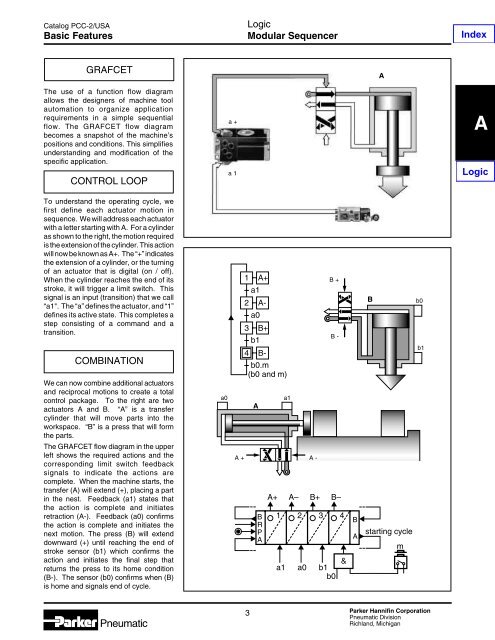
Catalog PCC-2/USABasic FeaturesLogicModular SequencerIndexGRAFCETAThe use of a function flow diagramallows the designers of machine toolautomation to organize applicationrequirements in a simple sequentialflow. The GRAFCET flow diagrambecomes a snapshot of the machine’spositions and conditions. This simplifiesunderstanding and modification of thespecific application.CONTROL LOOPa +a 1ALogicTo understand the operating cycle, wefirst define each actuator motion insequence. We will address each actuatorwith a letter starting with A. For a cylinderas shown to the right, the motion requiredis the extension of the cylinder. This actionwill now be known as A+. The “+” indicatesthe extension of a cylinder, or the turningof an actuator that is digital (on / off).When the cylinder reaches the end of itsstroke, it will trigger a limit switch. Thissignal is an input (transition) that we call“a1". The “a” defines the actuator, and “1”defines its active state. This completes astep consisting of a command and atransition.COMBINATIONWe can now combine additional actuatorsand reciprocal motions to create a totalcontrol package. To the right are twoactuators A and B. “A” is a transfercylinder that will move parts into theworkspace. “B” is a press that will formthe parts.The GRAFCET flow diagram in the upperleft shows the required actions and thecorresponding limit switch feedbacksignals to indicate the actions arecomplete. When the machine starts, thetransfer (A) will extend (+), placing a partin the nest. Feedback (a1) states thatthe action is complete and initiatesretraction (A-). Feedback (a0) confirmsthe action is complete and initiates thenext motion. The press (B) will extenddownward (+) until reaching the end ofstroke sensor (b1) which confirms theaction and initiates the final step thatreturns the press to its home condition(B-). The sensor (b0) confirms when (B)is home and signals end of cycle.a0A +1 A+a12 A-a03 B+b14 B-b0.m(b0 and m)ABRPAa1A -B +B -A+ A– B+ B–1 2 3 4a1 a0 b1b0&BABstarting cyclemb0b1Pneumatic3Parker Hannifin CorporationPneumatic DivisionRichland, Michigan