
You also want an ePaper? Increase the reach of your titles
YUMPU automatically turns print PDFs into web optimized ePapers that Google loves.
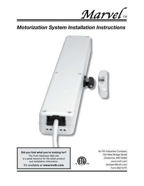
<strong>Marvel</strong> TMDangerTo help preventseverepersonal injuryor death• Read and understand instructions completely before beginninginstallation.• Wiring must be installed according to local and NationalElectrical Codes (N.E.C.)• Disconnect main power before beginning installation! Verifythat power is OFF at the main breaker or fuse panel by testingwith a voltage meter that you know is working correctly.• Connect power only after electrical connections are verified.• This equipment should be connected to a circuit capable ofproviding 1 Amp at 120 VAC of power per motorized unit.• Do not allow children to operate unit.• The <strong>Marvel</strong> Power System must not be used on windowsintended to meet egress codes.• The <strong>Marvel</strong> Power System is intended for indoor use only.• Save ALL instructions. Additional copies can be downloadedoff of our web site at: www.truth.com\technical support• Installer – please be sure to give ALL instructions to thehomeowner once installation is complete.• Unless a screen is locked into place to avoid a person reachinginto the window during operation, it is advised that the <strong>Marvel</strong>System not be installed in applications where the motor unit isless than eight feet above the floor.Motorization System Installation Instructions2
Table of Contents<strong>Marvel</strong> TMPreparationWhat you should know before starting.....4Getting started<strong>Hardware</strong> required....................................5Planning....................................................5Inspect Windows..................................5, 6InstallationMotor Installation.............................. 8 – 11Switch installation & Wiring Diagram......12Regulatory Compliance..........................12TroubleshootingCommon Problems.................................13Emergency procedures...........................13Service ....................................................14Motorization System Installation Instructions3
Brackets RequiredFor Face MountOn a Face Mount application you will needone set of Frame Face Mount Bracketsand one Sash Bracket for your window orskylight.Brackets RequiredFor Sill Mount<strong>Marvel</strong> TMOn a Sill Mount application determinewhich set of brackets you will need foryour window or skylight.Frame Brackets (1 pair)andFrameBracket"A" (2X)orSash BracketFrameBracket "B"(1 pair)andSash BracketSill Mount Drawing Page 6FrameBracket"A" 15.31"(389mm)"B" 15.191"(386mm)"W" "X" "Y" "Z"1.38"(35mm)1.63"(41mm)15.82"(402mm)15.86"(403mm).482"(12mm).728"(18.5mm)Motorization System Installation Instructions7
Motor Installation for Sill Mount Brackets2<strong>Marvel</strong> TMGraphics show bracket "A" butinstructions are for both brackets"A" and "B".3 & 4A1. Plan wire exit location on window or skylight2. Locate centerline (A) of window or skylight3. Align appropriate template (B) with centerline(A)4. Drill pilot holes for sash bracket.5aBA5. Determine the distance the motor unit will sitfrom the sash. (Make sure sash is fully closedbefore aligning motor unit.) The <strong>Marvel</strong> motorunit shuts off in the closing direction basedoff of amperage draw being monitored in thecontrol circuitry. This feature allows great flexibilityin the mounting position of the motorunit. For mounting suggestions and minimumconditions refer to <strong>Truth</strong>’s web site at www.truth.com\technical service.5ba) Choose which set of pivot holes in the motorunit that will be used with the selectedframe mounting bracket to position the motorcorrectly. Insert cap screws into the selectedpivot holes in the motor unit. (1 cap screw perside)POSITIONb) Slide frame bracket “A” onto cap screws andposition on sill using the template markingsas a starting location.5c.875"to sashminimumc) Align the frame bracket screw holes with thepre-drill center lines on the template. Movingmotor unit closer or farther from the sash untilit is in the correct position. Mark screw locations.Distance between sash and motor unitmust be greater than .875 [22.2mm]5dd) Drill pilot holes (2 for each bracket) into frame.Pilot holes should be centered in bracketscrew holes.Motorization System Installation Instructions8
Motor Installation for Sill Mount Brackets67<strong>Marvel</strong> TM6. Install sash bracket with screws provided.a) It is necessary to properly orient the sashbracket with respect to the motor unit in orderfor the quick disconnect feature to work. Thegraphic at left shows the proper orientation.The arrow on the sash bracket is to show howthe bracket is to be oriented with respect tohow the chain bends. In addition to the arrowon the sash bracket showing orientation, coloredstickers have also been included on thesash bracket and motor unit to help orient thebracket with respect to the motor unit. Ex: Ifthe green sticker is on top of the motor unitthe sash bracket should be oriented so thegreen sticker on the bracket is also on top9ABBracket7. Attach the motor unit with frame brackets tothe window or skylight frame with the screwsprovide.8. Complete electrical wiring and run test toassure function.B(refer to page 12 for wiringdiagram)9. Cycle motor unit in order to advance chainenough to snap chain into sash bracket.10. Cycle unit fully open and fully closed tocheck function.Motorization System Installation Instructions9
Motor Installation for Face Mount Brackets23 & 45a5b5cPOSITIONAPPLICATIONDEPENDANT.875 MIN.[22.2 mm]ASASHOPENAPPLICATIONDEPENDANT<strong>Marvel</strong> TM1. Plan wire exit location on window or skylight2. Locate centerline (A) of window or skylight3. Align appropriate template (B) with centerline(A)4. Drill pilot holes for sash bracket.5. Determine the distance the motor unit will sitfrom the sash. (Make sure sash is fully closedbefore aligning motor unit.) The <strong>Marvel</strong> motorunit shuts off in the closing direction basedoff of amperage draw being monitored in thecontrol circuitry. This feature allows great flexibilityin the mounting position of the motorunit. For mounting suggestions and minimumconditions refer to <strong>Truth</strong>’s web site at www.truth.com\technical service.a) Choose which set of pivot holes in the motorunit that will be used with the selectedframe mounting bracket to position the motorcorrectly. Insert cap screws into the selectedpivot holes in the motor unit. (1 cap screw perside)b) Slide frame bracket “A” onto cap screws andposition on sill using the template markingsas a starting location.c) Align the frame bracket screw holes with thepre-drill center lines on the template. Movingmotor unit closer or farther from the sash untilit is in the correct position. Mark screw locations.Distance between sash and motor unitmust be greater than 1.250 [31.7mm]d) Drill pilot holes (2 for each bracket) into frame.Pilot holes should be centered in bracketscrew holes.FRAMEAPPLICATION DEPENDANT5dMotorization System Installation Instructions10
Motor Installation for Face Mount Brackets67<strong>Marvel</strong> TM6. Install sash bracket with screws provided.a) It is necessary to properly orient the sashbracket with respect to the motor unit in orderfor the quick disconnect feature to work. Thegraphic at left shows the proper orientation.The arrow on the sash bracket is to show howthe bracket is to be oriented with respect tohow the chain bends. In addition to the arrowon the sash bracket showing orientation, coloredstickers have also been included on thesash bracket and motor unit to help orient thebracket with respect to the motor unit. Ex: Ifthe green sticker is on top of the motor unitthe sash bracket should be oriented so thegreen sticker on the bracket is also on top7. Attach the motor unit with frame brackets tothe window or skylight frame with the screwsprovide.98. Complete electrical wiring and run test toassure function. (refer to page 12 for wiringdiagram)9. Cycle motor unit in order to advance chainenough to snap chain into sash bracket.10. Cycle unit fully open and fully closed tocheck function.Motorization System Installation Instructions11
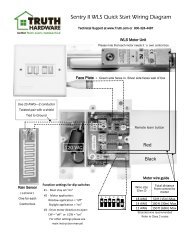
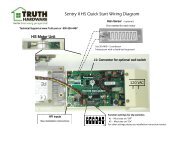
Switch Installation & Wiring Diagram*Additional <strong>Marvel</strong> unitscan be controlled by oneSPDT momentary contactswitch.• Check that the switchis properly rated for thetotal amperage draw ofall the units combined.• <strong>Marvel</strong> does not supportsynchronous operationwhere more than one<strong>Marvel</strong> unit is installedon a single sash.<strong>Marvel</strong> TM• It is recommended that the <strong>Marvel</strong> unit be controlled with a singlepole, double throw (SPDT) momentary contact switch. Theseswitches are typcially available through local electical supply stores.Please see the diagram below for how the unit is to be connected.* Note• The advantage of the momentary contact switch is that as soon asyour finger is removed from the switch the switch will return to thecenter, off position and the motor unit will stop at the desired position.• Please contact <strong>Truth</strong>’s Technical Support Department for applicationhelp when it is desired to control the <strong>Marvel</strong> with something otherthan a single pole, double throw (SPDT) momentary contact switch.General Electrical Specification• The <strong>Marvel</strong> has double electrical insulation.• An internal electronic limit switch controls the opening position.• The closing position is controlled by current sensing.• The amperage draw of a single <strong>Marvel</strong> unit at 120 V – 60 HZ is .12amps at a 45 pound load. The amperage draw at no load is .040amps.• It is recommended that the circuit be capable of providing 1 amp@120 VAC of power per window.• The input voltage for the unit can range from 80 V to 260 V for both50 Hz and 60 Hz.Product Certification• The <strong>Marvel</strong> has been certified to the following standards∆ ANSI / UL 325 – 2003 which is the standard for Door, Drapery,Gate Louver and Window Operators and Systems∆ AN / CSA C22,2 No. 68-92 which is the standard for Motor OperatedAppliances (Household and Commercial)Motorization System Installation Instructions12