
You also want an ePaper? Increase the reach of your titles
YUMPU automatically turns print PDFs into web optimized ePapers that Google loves.
An FKI Industries Company<br />
700 West - Bridge Street<br />
Owatonna, MN 55060<br />
www.truth.com<br />
techserv@truth.com<br />
Form 90059 R2<br />
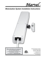
<strong>Sentry</strong> <strong>II</strong> TM<br />
HS Skylight Motorization System<br />
Installation Instructions<br />
French and Spanish versions available at www.truth.com/technicalsupport<br />
Made in USA
Danger: To help prevent severe personal injury or death:<br />
• Read and understand instructions completely before beginning<br />
installation.<br />
• Wiring must be installed by a qualified electrician according to<br />
local and National Electrical Codes (N.E.C.)<br />
• Disconnect main power before beginning installation! Verify<br />
that power is OFF at the main breaker or fuse panel by testing<br />
with a voltage meter that you know is working correctly.<br />
• Connect power only after motor connections and settings are<br />
verified.<br />
• This equipment does not provide a method to shut off power,<br />
and should be connected to a dedicated breaker or fused<br />
power circuit capable of providing 1 amp at 120 VAC of power<br />
per skylight unit.<br />
• The screen interlock MUST be correctly installed and is a<br />
required part of the power skylight system. It is intended to<br />
help prevent injury that could result from reaching into the<br />
skylight area during operation. The correct installation of the<br />
screen interlock is the responsibility of the installer. (The<br />
screen interlock is not required on skylights installed more<br />
than 8 feet above the floor.)<br />
• Do not allow children to operate the wall switch push buttons<br />
or remote control transmitter(s).<br />
Additional Safety Guidelines<br />
• When connecting the <strong>Sentry</strong> <strong>II</strong> system to accessories, read the<br />
installation instructions supplied with each accessory before<br />
beginning installation.<br />
• The <strong>Sentry</strong> <strong>II</strong> system is intended for indoor use only, with<br />
screens in place.<br />
• This product has been designed to open and close skylights<br />
and awning windows only. Any other use of this product is not<br />
supported by <strong>Truth</strong> <strong>Hardware</strong>.<br />
• Save ALL instructions. Additional copies can be downloaded<br />
off of our web site at: truth.com\technicalsupport<br />
• Installer – please be sure to give ALL instructions to the<br />
homeowner once installation is complete.<br />
2<br />
Did you find what you’re looking for? The <strong>Truth</strong> <strong>Hardware</strong> Web site is a great resource<br />
for the latest product and installation information. It’s available at www.truth.com
Table of Contents<br />
[<br />
Preparation<br />
Getting Started<br />
Installation<br />
Operation<br />
Accessories<br />
Troubleshooting<br />
Additional Info<br />
What you should know before starting ..4<br />
Parts list......................................................5<br />
Planning......................................................6<br />
Main wiring diagram .................................. 7<br />
Motor and controller installation .............. 8<br />
Screen Interlock .........................................11<br />
Normal operation .......................................14<br />
Battery backup ...........................................16<br />
Wall mounted switch panel .......................17<br />
Rain sensor.................................................17<br />
HPI ...............................................................19<br />
Status feedback..........................................20<br />
Power blind control....................................20<br />
General trouble shooting...........................22<br />
DIP switch settings ....................................23<br />
System reset...............................................23<br />
Status light code ........................................25<br />
Required maintenance...............................26<br />
Service ........................................................27<br />
Non-synchronous group ...........................28<br />
Synchronous Operation ............................29<br />
Regulatory compliance..............................31<br />
Did you find what you’re looking for? The <strong>Truth</strong> <strong>Hardware</strong> Web site is a great resource<br />
for the latest product and installation information. It’s available at www.truth.com<br />
3
Preparation<br />
What You Should Know Before Starting<br />
Languages: This installation booklet is available in French and Spanish on our<br />
web site at www.truth.com/technicalsupport.<br />
Supply Voltage Note: The supply voltage range for the <strong>Sentry</strong> <strong>II</strong> power skylight<br />
system is very flexible to accommodate supply voltages available from many<br />
different countries. The input (supply) voltage range is 90 to 264 VAC at a<br />
frequency range of 47 to 440 Hz. For practical purposes, the supply voltage<br />
referenced in this document is 120 volts at 60 Hz commonly used in the United<br />
States.<br />
Operating Environment: The operating temperature range must be maintained<br />
between 140º F (60º C) to -5º F (-20º C).<br />
Single motor vs. multiple (synchronous) motor application: Most<br />
applications of the <strong>Sentry</strong> <strong>II</strong> HS system will be a single motor on a single skylight.<br />
However, the <strong>Sentry</strong> <strong>II</strong> HS motor system can be used in a number of different<br />
applications depending on the size and weight of your skylight lid. The skylight<br />
lid must weigh less than 160 lbs. (80 lbs. at the chain) for a single motor<br />
installation. If your skylight lid is heavier than 160 lbs., multiple motors (up to 4)<br />
can be used to lift a single skylight lid. The maximum skylight weight for 4<br />
motors is 400lbs. This is called a synchronous motor application. Please refer to<br />
page 29 for the details of this installation.<br />
Multiple motors on separate skylights: There is a way of wiring several<br />
motors on different skylights together so that they all will respond to one wall<br />
switch or one HPI input. Please refer to page 28 for the details of this<br />
installation.<br />
4<br />
Did you find what you’re looking for? The <strong>Truth</strong> <strong>Hardware</strong> Web site is a great resource<br />
for the latest product and installation information. It’s available at www.truth.com
Getting Started<br />
Item<br />
Part Number<br />
1. Motor Cover 12481.XX (not part of kit)<br />
2. Base Plate Not sold separately<br />
3. Chain Liner Not sold separately<br />
4. Control Unit 13027<br />
5. Motor Unit 12473.92<br />
6. Chain 11533<br />
7. Sprocket 30654<br />
8. Terminal block<br />
9. Strain Relief Items 8 thru 9 are part of<br />
10. Screen Interlock hardware kit # 12482<br />
11. Rain sensor<br />
12. Screws<br />
(4) Size A – (#12-24 X 5/8”, TF, Ph FH, self threading machine screws)<br />
(2) Size B (#6-32 X 3/8” T23, Ph PH machine screws)<br />
(2) Size C (#10 X 3/4” Ph PH sheet metal screws)<br />
(2) Size D (#10 X 3/4” Ph PH sheet metal screws)<br />
Note:<br />
• No wire is included. See wiring diagram on page 28 for wire requirements.<br />
• To replace lost or broken parts, please go to www.truth.com to locate distributor<br />
Did you find what you’re looking for? The <strong>Truth</strong> <strong>Hardware</strong> Web site is a great resource<br />
for the latest product and installation information. It’s available at www.truth.com<br />
5
Planning<br />
Important: If you are not the homeowner, it is important to contact the<br />
homeowner and discuss how they want to control a group of skylights. It may be<br />
very difficult to change the installation to meet the homeowner’s desires once<br />
installation is complete.<br />
Please consider:<br />
• In case of a power outage the <strong>Sentry</strong> <strong>II</strong> power skylight system does not<br />
have manual override. If it is important to be able to close the skylights<br />
without power, consider installing a battery back-up system.<br />
• There are a number of other control options available:<br />
o Remote Control Has Built-in Thermostat for those applications<br />
where it is desirable to open and close skylights based on<br />
temperature. Just set the temperature and place the remote in the<br />
area where you want the temperature controlled. Every <strong>Sentry</strong> <strong>II</strong><br />
HS unit is remote control enabled.<br />
o A Rain Sensor comes standard with each unit. If you choose to<br />
install the rain sensor, each control unit needs a separate rain<br />
sensor. Consult main wiring diagram for wiring requirements.<br />
o Power mini blinds - The <strong>Sentry</strong> <strong>II</strong> control unit is capable of<br />
controlling power mini blinds (supplied by others). See page 20 for<br />
additional information. Consult main wiring diagram for wiring<br />
requirements.<br />
o Skylight position feedback - The <strong>Sentry</strong> <strong>II</strong> control unit is capable<br />
of providing skylight position feedback (open or closed). See page<br />
20 for additional information. Consult main wiring diagram for<br />
wiring requirements.<br />
o Integrated control with other control systems - The <strong>Sentry</strong> <strong>II</strong><br />
power skylight system can be integrated with other automated<br />
control systems. Some examples are home automation systems,<br />
thermostats and security systems. See the HPI section on page 18<br />
for additional information. Consult main wiring diagram for wiring<br />
requirements if used.<br />
• Plan your circuits based on 1 amp of power at 120 VAC per motor unit.<br />
• The primary means of skylight control is the remote control. An optional<br />
wall mounted switch panel is available if required.<br />
o If installing a wall mounted switch panel – See main wiring diagram<br />
for wiring details. Plan your wiring routes carefully. Low voltage<br />
wires must not be run parallel to high voltage wires.<br />
6<br />
Did you find what you’re looking for? The <strong>Truth</strong> <strong>Hardware</strong> Web site is a great resource<br />
for the latest product and installation information. It’s available at www.truth.com
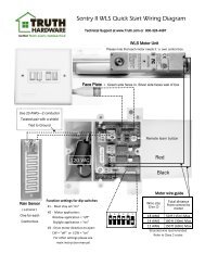
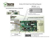
Main wiring diagram<br />
Did you find what you’re looking for? The <strong>Truth</strong> <strong>Hardware</strong> Web site is a great resource<br />
for the latest product and installation information. It’s available at www.truth.com<br />
7
Motor Installation<br />
Please Note: If the chain base and motor unit are pre-installed on the skylight,<br />
skip to step 7.<br />
1. Verify Skylight Weight<br />
Important Skylight Information:<br />
• The skylight lid weight must not exceed 80 lbs. (36 kg) at the chain.<br />
• If over 80 lbs. or wider than 40” refer to the Synchronous Motor<br />
section of the manual.<br />
80 lbs. max<br />
Chain carries ½ of total lid weight<br />
2. Install Chain Base<br />
• Remove existing manual operator and/or chain base if present.<br />
• Install the chain base included with the kit (even if the current unit appears<br />
to be the same).<br />
• Secure chain base to skylight frame with #10 screws (not supplied) in the<br />
locations shown. Where possible, reuse the fasteners used by the<br />
skylight manufacturer.<br />
• Secure vent bracket to skylight vent.<br />
Important: Check chain, vent bracket and lid alignment to ensure smooth<br />
operation. Adjust mounting positions as needed.<br />
8<br />
Did you find what you’re looking for? The <strong>Truth</strong> <strong>Hardware</strong> Web site is a great resource<br />
for the latest product and installation information. It’s available at www.truth.com
3. Install the Control Box<br />
DANGER: 120 VAC supply power must be off until instructed to turn it on.<br />
• Remove high voltage protection cover.<br />
• Install Hit-Loc strain relief as shown.<br />
• Route 120 VAC supply wiring through the rear inlet and strain relief on<br />
control box.<br />
• Install the motor control box by aligning the tabs on the box with the<br />
notches on the chain base.<br />
• Use (2) #10 X ¾ Phillips Pan Head Machine screws in the locations<br />
shown.<br />
Strain Relief<br />
Hook tabs over<br />
edge of base.<br />
Did you find what you’re looking for? The <strong>Truth</strong> <strong>Hardware</strong> Web site is a great resource<br />
for the latest product and installation information. It’s available at www.truth.com<br />
9
4. Install Motor Drive onto Chain Base<br />
• Install the motor drive onto the chain base, being sure to align the hex<br />
drive with the hole in the 5 pointed drive sprocket. Once the motor is fully<br />
engaged with the chain base the control box is effectively locked into the<br />
chain base/motor drive assembly.<br />
• Secure with (4) #12-24 X 5/8” Ph FH Machine Screws in the locations<br />
shown.<br />
5. Install Motor Drive Cable<br />
Connect motor drive cable to the control unit as shown in the diagram.<br />
Important: The female connector on the end of the wire harness must be<br />
properly oriented with the male connector on the control unit or the motor<br />
system will not work.<br />
Connect<br />
motor drive<br />
cable to<br />
control unit<br />
10<br />
Did you find what you’re looking for? The <strong>Truth</strong> <strong>Hardware</strong> Web site is a great resource<br />
for the latest product and installation information. It’s available at www.truth.com
6. Install Screen Interlock!<br />
DANGER: The screen interlock must be correctly installed on all skylights<br />
less than 8 feet (2.4 meters) above the floor. It is intended to prevent<br />
personal injury and/or skylight damage during operation. The correct<br />
installation of the screen interlock is the responsibility of the installer.<br />
Screen interlock installation:<br />
• Install screen interlock to the screen frame as shown below using #6-<br />
32 X 3/8” Phillips PH, Self Threading, Machine Screw.<br />
• Refer to wiring diagram on page 28 for wire connections.<br />
• Remove the jumper installed in the Grey terminals on terminal block<br />
“10”. Connect screen interlock leads to the same terminals. If this is<br />
a Follower motor leave jumper in place and only connect interlock to<br />
the Leader.<br />
Note: Wire orientation or polarity does not matter for this connection.<br />
#6-32 X 3/8” Phillips PH,<br />
Self Threading, Machine Screw<br />
Screen Interlock<br />
Did you find what you’re looking for? The <strong>Truth</strong> <strong>Hardware</strong> Web site is a great resource<br />
for the latest product and installation information. It’s available at www.truth.com<br />
11
7. Connect Control Wires<br />
Note: See “Optional Accessories” section for information on additional<br />
control methods.<br />
• Complete wiring diagram can be found on page 26.<br />
• Available Accessories include:<br />
o Rain Sensor, See page 17<br />
o HPI Inputs, See page 19<br />
o Status Feedback, See page 20<br />
o Wall Switch Panel, See page 17<br />
o Power Shades/Blinds, See page 20<br />
• Route low voltage wires through wire pass-through location and into<br />
control board opening.<br />
• Connect low voltage wires to the control panel as outlined for each<br />
accessory.<br />
• Accessories and other control options are wired to the motor<br />
designated as the “Leader” only for Synchronous Motor Operation.<br />
Low voltage wire<br />
pass-through<br />
8. Connect Power Wires<br />
• Connect high voltage wires (120 VAC) to the wire harness and terminal<br />
block as shown.<br />
DANGER: no power should be present at this time. Power to this<br />
equipment should be shut off at the main breaker or fuse panel until<br />
installation is complete.<br />
• Connector locks onto tabs in box once the wires are connected.<br />
• Verify wire connections then re-install high voltage protection cover.<br />
Connect:<br />
White to White,<br />
Black to Black,<br />
Green to Ground.<br />
Re-install<br />
wire cover<br />
Tabs for<br />
connector<br />
12<br />
Did you find what you’re looking for? The <strong>Truth</strong> <strong>Hardware</strong> Web site is a great resource<br />
for the latest product and installation information. It’s available at www.truth.com
9. Install Cover<br />
• Remove the center trim button from the cover (<strong>Sentry</strong> <strong>II</strong>) and locate the<br />
mounting screw beneath.<br />
• Slip the motor cover over the drive motor and control box. Start with the<br />
notched edge of cover hooked behind the motor/control box closest to the<br />
glass. Be sure that the lens in the side of the cover aligns with the notch<br />
in the control box before pushing the motor cover down. Then swing the<br />
front edge of the cover down into the flat position.<br />
• Fasten the motor cover using the pan head screw found under trim button<br />
(#6-32 X 3/8” Phillips PH, Self Threading, Machine Screw).<br />
• WARNING: Use of a longer screw will damage motor. (If needed, a<br />
spare screw is supplied in the hardware pack.)<br />
Center trim button &<br />
Mounting screw<br />
Lens for Status LED<br />
LED Notch<br />
10. Power Up and Initialization<br />
Important notice: To help insure a successful power up be sure that the<br />
following steps have been completed:<br />
• Check that the end of the operator chain is connected to the skylight.<br />
(See Step 2)<br />
• Verify the screen interlock is installed and connected OR, that there is<br />
a jumper installed across the two gray terminals on terminal block 10.<br />
(See Step 6)<br />
• Units that have Followers need to be powered up at the same time.<br />
Power up<br />
• Apply 120 VAC power to the control unit<br />
Note: Upon power-up the skylight will automatically close. (If skylight<br />
is already closed, the motor will momentarily start and stop verifying<br />
the skylight is closed.)<br />
Did you find what you’re looking for? The <strong>Truth</strong> <strong>Hardware</strong> Web site is a great resource<br />
for the latest product and installation information. It’s available at www.truth.com<br />
13
Initialization<br />
The power skylight system is now ready to be initialized. Initialization occurs<br />
automatically when the motor unit receives its first “Open” command.<br />
• Upon receiving an “Open” command for the very first time after original<br />
power up, the unit will automatically run through an initialization cycle.<br />
Initialization consists of one full open and closed cycle.<br />
• The “Open” command can be given from any of three control devices:<br />
o Remote Control (Note: The remote must first be<br />
programmed – see step 11)<br />
o Wall switch<br />
o HPI Input<br />
• During initialization the LED on the motor cover (and on the switch face<br />
plate if installed) will display a “Red” LED.<br />
Note: This cycle is necessary for the unit to establish its operating<br />
parameters which will be stored in permanent memory. Once<br />
permanent memory is established it is unaffected by loss of power of<br />
any duration.<br />
11. Program Remote Control<br />
If a remote control is part of the installation it should now be programmed to<br />
the control unit. Refer to set-up instructions included with the remote control<br />
for proper set-up.<br />
Skip this step if the installation does not include a remote control.<br />
Normal Operation<br />
14<br />
From the remote control:<br />
To open the skylight:<br />
• Select “Unit” number (or “all”) for the skylight you want to control.<br />
• Press “Open” button.<br />
Note: The full open position varies with operating hardware and<br />
curb height of the skylight. The typical stop position is approx. 90%<br />
of full open.<br />
To close the skylight:<br />
• Select “Unit” number (or “all”) for the skylight you want to control.<br />
• Press “Close” button.<br />
For an intermediate open position,<br />
• Press the “opposite” function while the motor is running - the motor<br />
will stop in that position.<br />
Further information on using the remote control can be found in the<br />
instructions packaged with the remote.<br />
Did you find what you’re looking for? The <strong>Truth</strong> <strong>Hardware</strong> Web site is a great resource<br />
for the latest product and installation information. It’s available at www.truth.com
Status Light Indicator<br />
During operation the status light located on the skylight motor cover<br />
will be steady green to indicate normal operation. (See “Status<br />
Codes” on page 25 for more information.)<br />
From the optional wall switch control:<br />
To open the skylight:<br />
• Press skylight “Open” button.<br />
Note: The full open position varies with operating hardware and<br />
curb height of the skylight. The typical stop position is approx. 90%<br />
of full open.<br />
To close the skylight:<br />
• Press skylight “Close” button.<br />
For an intermediate open position,<br />
• Press the “opposite” function while the motor is running - the motor<br />
will stop in that position.<br />
Status Light Indicator<br />
During operation the status light located in the skylight motor and on<br />
the switch face plate will be steady green to indicate normal operation.<br />
(See “Status Codes” on page 25 for more information.)<br />
Note: Any time there is a power outage, the skylights will automatically<br />
close when power is restored. The system is programmed this way<br />
because the system will not recognize any attempts to open or close<br />
the skylight while the power is off including attempts by the rain sensor<br />
(if installed) to close. Therefore, the safest position for the skylight to<br />
be in when power is restored is closed. All controls will return to<br />
normal function once power is restored.<br />
Buttons located on wall switch:<br />
Close<br />
Skylight<br />
Open<br />
Skylight<br />
Status<br />
Light<br />
Open<br />
Blind<br />
Close<br />
Blind<br />
Did you find what you’re looking for? The <strong>Truth</strong> <strong>Hardware</strong> Web site is a great resource<br />
for the latest product and installation information. It’s available at www.truth.com<br />
15
Accessories<br />
Battery Backup<br />
Battery backup should be used to supply emergency power when operation<br />
of the power skylight system must be maintained in the event of a power<br />
outage. (Please note: A battery back-up is not required to provide memory<br />
back-up for the <strong>Sentry</strong> <strong>II</strong> system.)<br />
<strong>Truth</strong> recommends the use of a UPS (uninterruptible power supply) as a<br />
battery backup. They are widely available through a variety of retail and<br />
commercial outlets and are primarily used to supply emergency backup for<br />
computer equipment. (<strong>Truth</strong> <strong>Hardware</strong> is not a supplier of battery back-up<br />
systems.)<br />
To determine the proper VA rating for a UPS, take 50 watts and multiply by<br />
the number of skylights to be backed up by a given UPS. Below is a list of<br />
the manufacturers who produce uninterruptible power supplies which <strong>Truth</strong><br />
<strong>Hardware</strong> has approved as compatible with our power skylight systems.<br />
Powerware<br />
Forum <strong>II</strong>I<br />
8609 Six Forks Road<br />
Raleigh, NC 27615<br />
(800) 554-3448<br />
(919) 872-3020<br />
www.powerware.com<br />
American Power Conversion<br />
132 Fairgrounds Road<br />
West Kingston, RI 02892<br />
(800) 788-2208<br />
(401) 789-5735<br />
www.apcc.com<br />
Tripp Lite<br />
1111 West 35th Street<br />
Chicago, IL 60609<br />
(773) 869-1111<br />
www.tripplite.com<br />
Minuteman (brand)<br />
1455 LeMay Drive<br />
Carrollton, TX 75007<br />
(800) 238-7272<br />
(972) 446-7363<br />
www.minuteman-ups.com<br />
16<br />
Did you find what you’re looking for? The <strong>Truth</strong> <strong>Hardware</strong> Web site is a great resource<br />
for the latest product and installation information. It’s available at www.truth.com
Wall Mounted Switch Panel (Optional)<br />
An optional wall mounted switch panel can be ordered to control a skylight (or<br />
skylights) from a wall mounted switch panel. The switch panel can be used in<br />
conjunction with a remote control or by itself.<br />
Installation – See installation instructions supplied with Switch Panel. For<br />
multiple units the switch is connected to the Leader.<br />
Important: It is not recommended to connect other input devices in place of<br />
the membrane switches on the wall switch panel.<br />
Helpful Hint: The cover plate is only available in one configuration and color.<br />
The cover plate can however, be painted or wall paper can be applied to<br />
change its appearance.<br />
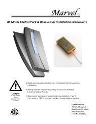
Rain Sensor (included)<br />
The sensor will close the skylight when “beading” moisture is present on the<br />
surface of the rain sensor grid. It will also cause the green LED on the motor unit<br />
to blink (indicating moisture is present) while the skylight is closing. Once the<br />
rain sensor grid is dry, normal operation will resume.<br />
Warning: Do not install the rain sensor if the skylight is being controlled as a<br />
smoke vent to vent smoke in case of a fire. The rain sensor overrides all other<br />
inputs. (see HPI, page 19).<br />
Note: Rain sensor installation is optional.<br />
Installation of Rain Sensor<br />
• Locate the desired mounting location for the rain sensor. It should be<br />
as horizontal as possible to accumulate rain.<br />
• Route rain sensor wires into control unit housing.<br />
Note: Do not route rain sensor wire through the operator chain port,<br />
damage to rain sensor wire will be a likely result.<br />
Did you find what you’re looking for? The <strong>Truth</strong> <strong>Hardware</strong> Web site is a great resource<br />
for the latest product and installation information. It’s available at www.truth.com<br />
17
Interior Mounting<br />
Exterior Mounting<br />
Install Rain Sensor Grid<br />
• Connect the rain sensor wires to the Grey & Green terminals on<br />
Port “5”.<br />
Rain Sensor Guidelines:<br />
• Install the sensor with "grid" exposed to outside elements where the rain<br />
has a clear, unobstructed path to the rain sensor. Consider prevailing<br />
winds.<br />
• If the desired location of the rain sensor exceeds the wire length supplied,<br />
use 22 AWG - 2 conductor shielded, twisted pair 50 ft (15m) maximum<br />
length.<br />
Important: Connect shield to earth ground to reduce interference from<br />
lightning and other electrical devices.<br />
• The sensor can be installed outside (maximum sensitivity) or inside vent<br />
edge (minimum maintenance)<br />
• Recommended maintenance: Regular cleaning of sensor panel with a mild<br />
cleaning agent is recommended. Dirt or debris can cause the vent to stay<br />
closed even when rain is not present.<br />
Note:<br />
• There is a 10 second delay from the time the rain sensor senses moisture<br />
to the time the skylight actually starts to close.<br />
• When the skylight is closed because of rain, it can be forced to open by<br />
holding down the “Open” button even when the sensor is “wet”, however,<br />
the skylight will immediately re-close once the open button is released.<br />
18<br />
Did you find what you’re looking for? The <strong>Truth</strong> <strong>Hardware</strong> Web site is a great resource<br />
for the latest product and installation information. It’s available at www.truth.com
High Priority Inputs (HPI)<br />
The control unit located at the skylight includes inputs to allow skylight control<br />
from other devices such as thermostats, home automation systems, security<br />
systems, smoke evacuation systems, etc. These inputs are called High Priority<br />
Inputs (HPI). There is an input for “Open” and an input for “Close”. The inputs<br />
are designed to be controlled with low voltage dry contacts (relay).<br />
Note: See main wiring diagram on page 7 for proper hook-up.<br />
Input Function - HPI Close<br />
1. When connected by a continuous contact closure, the skylight will<br />
fully close. All other input devices (except for HPI Open) will be<br />
“locked-out” until the contact closure is re-opened<br />
2. When connected by momentary contact closure, the skylight will<br />
close. There will be a minimum delay of 3 seconds before system<br />
will react.<br />
• A contact closure of 3 seconds is needed to activate a “close”<br />
command.<br />
Input Function - HPI Open<br />
1. When connected by a continuous contact closure, the skylight will<br />
fully open. All other input devices will be “locked-out” until the<br />
contact closure is re-opened. There will be a minimum delay of 3<br />
seconds before system will react.<br />
2. When connected by momentary contact closure, the skylight will<br />
open. There will be a minimum delay of 3 seconds before system<br />
will react.<br />
• A contact closure of 3 seconds is needed to activate an “open”<br />
command.<br />
Intermediate Open position<br />
The skylight can be stopped in an intermediate position with a ½<br />
second momentary contact closure across the contacts for the<br />
direction opposite the skylight travel. For instance, if the skylight is<br />
opening, a momentary contact closure of ½ second across the HPI<br />
“Close” contacts will stop the skylight.<br />
Wiring<br />
18-2 twisted pair is recommended up to 150 feet maximum.<br />
Control Switch Options<br />
• Some home automation companies offer control switches that can<br />
be used to control the <strong>Sentry</strong> <strong>II</strong> HS control unit through the HPI<br />
inputs. Consult the <strong>Truth</strong> <strong>Hardware</strong> web site for more information.<br />
(www.truth.com/technicalsupport)<br />
Did you find what you’re looking for? The <strong>Truth</strong> <strong>Hardware</strong> Web site is a great resource<br />
for the latest product and installation information. It’s available at www.truth.com<br />
19
Helpful Information<br />
• Voltage supplied by HPI input is: 12 VDC @ 5mA.<br />
• When multiple input sources are used to control a given set of<br />
skylights consult the Input Command Priority Table on the <strong>Truth</strong><br />
<strong>Hardware</strong> Web site (truth.com) to insure you receive the proper<br />
skylight response to multiple input command sources.<br />
System Status Feedback<br />
The <strong>Sentry</strong> <strong>II</strong> control unit is capable of providing feedback regarding whether<br />
the skylight is closed or not closed. (System feedback is not capable of<br />
providing true skylight position.)<br />
Note: See main wiring diagram on page 7 for proper hook-up.<br />
Status output function:<br />
The status output functions as a relay. When the output is closed<br />
(relay contacts closed), the skylight is fully closed. When the output is<br />
open (relay contacts open), the skylight is not fully closed.<br />
Feedback output (contact closure) maximum ratings:<br />
Rated Load:<br />
0.50 A at 125VAC, 1 A at 24VDC<br />
Minimum Load:<br />
1mA, 5VDC<br />
Max. operating voltage: 125 VAC, 60 VDC<br />
Max. operating current: 1A<br />
Max. switching capacity: 62.50 VA, 30W<br />
Power Blind Control<br />
The <strong>Sentry</strong> <strong>II</strong> control unit is capable of controlling 24 VDC blinds or shades.<br />
<strong>Truth</strong> <strong>Hardware</strong> does not supply power blinds or shades. We only supply a<br />
convenient control method with the same <strong>Sentry</strong> <strong>II</strong> control system. Therefore, it<br />
is very important that a blind system be chosen that is compatible with the <strong>Sentry</strong><br />
<strong>II</strong> control system. Please use the following electrical specifications when<br />
selecting a power blind or shade:<br />
• Operating Voltage: 24 VDC<br />
• Maximum current draw: 1 amp (at 24 VDC)<br />
• Power blind system must be range protected with internal limit<br />
switches.<br />
Note: <strong>Truth</strong> <strong>Hardware</strong> does not supply the installation instructions for the<br />
installation of the motorized blinds themselves. Please consult instructions<br />
supplied with the blinds for installation. If it is installed on a Synchronous system<br />
the blind would be connected to the Leader only.<br />
20<br />
Did you find what you’re looking for? The <strong>Truth</strong> <strong>Hardware</strong> Web site is a great resource<br />
for the latest product and installation information. It’s available at www.truth.com
Control unit setup for Power Blind installation<br />
• Locate DIP switch block on the control unit labeled “S2”. (See main<br />
wiring diagram on page 7.) Set DIP switch #4 to the “on” position.<br />
(Important: Do not change any other switch positions!)<br />
6<br />
5<br />
4<br />
3<br />
2<br />
1<br />
off<br />
on<br />
S2<br />
• Consult blind installation instructions for proper blind motor polarity.<br />
Locate the positive wire to open the motorized blind. Connect it to the<br />
“Grey” terminal on terminal block #12. (See main wiring diagram.)<br />
Note:<br />
• If unable to determine the positive wire to open the motorized blind,<br />
the blind motor can be connected in either orientation. However, if<br />
the blinds open in the opposite direction from the button pressed,<br />
the two wires will need to be reversed.<br />
• When the blinds are used in combination with the HPI “Open”<br />
function, the blinds will open automatically before the skylight is<br />
opened. This is because this feature is often used for smoke<br />
evacuation when connected to a smoke alarm.<br />
The following companies can provide information on blinds or shades that are<br />
compatible with the <strong>Sentry</strong> <strong>II</strong> Motor System. Be sure to ask for the<br />
“Motivator” series made by Verosol. Try these Verosol distributors:<br />
OEM Shades Inc.<br />
Shades Unlimited<br />
700 First Ave. 545 Brooklyn Road<br />
Ford City PA 16226 Mount Tabor VT 05739<br />
724-763-3600 802-293-2478<br />
www.oemshades.com www.skylightshades.com<br />
Did you find what you’re looking for? The <strong>Truth</strong> <strong>Hardware</strong> Web site is a great resource<br />
for the latest product and installation information. It’s available at www.truth.com<br />
21
Trouble Shooting<br />
Note: Additional Technical assistance can be found by logging onto:<br />
www.truth.com/technicalsupport<br />
Motor does not run<br />
• Check to make sure power is on<br />
• Check to make sure the screen interlock is installed and connected<br />
properly (See page 11.) or, check to make sure the jumper is installed<br />
across the two gray terminals on block 10. (See main wiring diagram on<br />
page 7.)<br />
Skylight closes for unknown reason<br />
• Check to make sure the rain sensor is clean – debris or bird droppings can<br />
activate the rain sensor. Clean with a mild soap.<br />
• The motor system may have closed the skylights due to a power outage.<br />
Normal operation is to close the skylights when the power comes back on.<br />
The motor will not respond from the wall switch<br />
• Verify the connector on the back of the switch is connected properly to the<br />
control unit. See installation instructions supplied with the wall switch unit.<br />
Skylight does not open fully<br />
• The motor system is programmed to only open a skylight to 90% of full<br />
opening. This is done to protect the hardware from repeated high<br />
stresses. Full opening can be achieved by pressing the open button<br />
repeatedly once the skylight has stopped.<br />
The skylight will not open more than a couple of inches<br />
• The control system needs to be re-initialized. Follow “System Reset”<br />
procedure below.<br />
• If the problem reoccurs, the lifting chain my need to be lubricated. Use a<br />
dry lubricant only.<br />
When bench testing the motor system, the motor will not stop<br />
• This is normal operation. The control unit is looking for a current rise<br />
caused by a motor stall to turn the motor off.<br />
Skylight does not fully close<br />
• The control system needs to be re-initialized. Follow “System Reset”<br />
procedure below.<br />
Motor system is not functioning as expected<br />
• Interrupting the power to the control unit for a short period of time<br />
(approximately 30 seconds) will clear some operating errors. When power<br />
is re-applied the unit should close automatically. Normal function should<br />
be restored.<br />
• If normal function does not return, a partial or full system reset my be<br />
needed. See System Reset on page 22.<br />
22<br />
Did you find what you’re looking for? The <strong>Truth</strong> <strong>Hardware</strong> Web site is a great resource<br />
for the latest product and installation information. It’s available at www.truth.com
DIP Switch Settings<br />
The DIP switches located on the control board are used to set certain system<br />
configurations. In most cases the DIP switches will not need to be changed.<br />
However, if you suspect they may have been changed for some reason, the<br />
following is the correct set up configuration when a single motor is installed<br />
on a single skylight. If your set-up is different, follow the DIP switch set-up<br />
instructions supplied with the installation instructions for your particular<br />
application.<br />
6<br />
5<br />
4<br />
3<br />
2<br />
1<br />
off<br />
on<br />
S2<br />
1 – off<br />
2 – on<br />
3 – off<br />
4 – off = No motorized blind connected<br />
on = Motorized blind connected<br />
5 & 6 – off<br />
DIP Switch setting for a single motor is installed on a single skylight<br />
Important: Any DIP switch changes must be done with the 120 VAC power<br />
disconnected. If the power is not disconnected the DIP switch change may<br />
not be recognized.<br />
System Reset<br />
There are times when the motor system operating characteristics can change.<br />
This can occur for a number of reasons. A couple of examples are if the<br />
motor has hit an obstruction or the manual hardware requires cleaning or<br />
service. The motor system is designed to recognize unusually high torque<br />
situations during operation and then stop short of that area on subsequent<br />
operations to protect the motor system and skylight hardware from damage.<br />
If this occurs, the cause of the high torque situation must first be identified<br />
and removed. A qualified skylight service technician may be required. Once<br />
the cause has been identified and removed, the skylight system needs to be<br />
re-initialized to restore full range of motion. Follow the “system reset” options<br />
below.<br />
A system reset will cause the motor system to re-learn most of it operating<br />
parameters. Once initiated, the skylight will close (if not already closed) then<br />
fully open and fully close. Once complete, the control system should function<br />
normally.<br />
There are two different types of resets: Partial and Total.<br />
Did you find what you’re looking for? The <strong>Truth</strong> <strong>Hardware</strong> Web site is a great resource<br />
for the latest product and installation information. It’s available at www.truth.com<br />
23
Partial System Reset:<br />
A partial systems reset will restore normal operation under almost all<br />
circumstances and is the easiest to initiate. There are three ways a partial<br />
systems reset can be initiated.<br />
• Through the wall switch: First turn power off for 30 seconds then<br />
reapply. With the skylight closed, simultaneously press both the<br />
skylight and blind “close” buttons. When the status light turns red<br />
release the buttons. The skylight will cycle open and then close.<br />
Close<br />
Skylight<br />
Status<br />
light<br />
Close<br />
Blind<br />
• Through the remote control: First turn power off for 30 seconds then<br />
reapply. Then set the remote to the appropriate “Unit Code” and<br />
simultaneously press and hold the “Unit” & “Mode” keys down for 15<br />
seconds.<br />
Unit<br />
Motor<br />
Therm<br />
Blind<br />
F Set C<br />
Unit<br />
Open<br />
Close<br />
Mode<br />
To initiate a partial system<br />
reset: press and hold the<br />
Unit and Mode buttons<br />
simultaneously until the<br />
“Motor” indicator flashes<br />
24<br />
Did you find what you’re looking for? The <strong>Truth</strong> <strong>Hardware</strong> Web site is a great resource<br />
for the latest product and installation information. It’s available at www.truth.com
Total System Reset:<br />
If the operational issue is not resolved with a partial reset as described above<br />
a total system reset may be needed. To initiate a total system reset:<br />
1. Turn power off.<br />
2. Change all DIP switches to “off”.<br />
3. Turn power back on for 30 seconds.<br />
4. Turn power off.<br />
5. Change DIP switches back to original position.<br />
6. Turn power back on and the skylight will close automatically.<br />
7. Push button on remote (or wall switch or HPI open command) to open<br />
skylight.<br />
The motor system will begin a reset cycle to re-learn all of its operating<br />
parameters. Once initiated, the skylight will fully open and then fully close.<br />
Once complete, the control system should function normally.<br />
Status Light Codes<br />
During setup and operation the status light on the skylight motor (and switch<br />
panel if installed) will provide information regarding system function. The<br />
following list will help explain the different conditions indicated:<br />
Flashing Red:<br />
1. Upon power-up - This indicates that the dip switches have not been set<br />
correctly. See DIP Switch Settings on page23.<br />
2. During motor operation – Indicates that the motor has run into an<br />
obstruction or that the skylight hardware requires service. This occurs<br />
when the load on the motor exceeds normal operating parameters.<br />
Solid Red:<br />
1. Motor not running<br />
• Check to make sure the screen interlock is installed and connected<br />
properly (If required - see step 6 and main wiring diagram on page 26.)<br />
• If screen interlock is not installed, check to be sure the jumper is<br />
installed. (See step 6.)<br />
2. During motor operation<br />
Solid Green:<br />
• The motor is running through its initialization cycle to learn the range of<br />
skylight travel. This is normal operation. The red light will go out once<br />
the initialization cycle is completed successfully.<br />
1. During motor operation<br />
Did you find what you’re looking for? The <strong>Truth</strong> <strong>Hardware</strong> Web site is a great resource<br />
for the latest product and installation information. It’s available at www.truth.com<br />
25
• Indicates normal motor operation. The light will stay lit only while the<br />
motor is running.<br />
2. Motor not running (LED stays lit for 2 – 3 minutes)<br />
• The cable between the control unit and the motor may have become<br />
disconnected. See step 5.<br />
• The connector at the end of the black and red wires coming from the<br />
back of the motor may have become disconnected from J2 located on<br />
the small circuit board at the back of the motor assembly.<br />
• The jumper or screen interlock has been disconnected or has been<br />
removed. Verify connection. See step 6.<br />
Flashing Green:<br />
1. Under normal operation it indicates the rain sensor has been activated.<br />
The light will flash green only while the skylight is closing.<br />
2. Indicates set up mode for the hand held remote. See set up instructions<br />
for the remote control.<br />
Required Maintenance<br />
The required maintenance for your new power skylight system is minimal. To<br />
insure years of trouble-free operation the following maintenance should be<br />
performed:<br />
• Clean and lubricate the skylight chain. Be sure to use a dry lubricant.<br />
This should be done once a year in non-coastal environments.<br />
• In coastal environments the chain should be thoroughly cleaned with<br />
fresh water to remove any salt residue. This should be done every 3 –<br />
6 months depending on the severity of the coastal environment. A dry<br />
lubricant should be applied after each cleaning.<br />
• If the rain sensor is used, it should be cleaned every 3 – 6 months with<br />
a mild detergent.<br />
26<br />
Did you find what you’re looking for? The <strong>Truth</strong> <strong>Hardware</strong> Web site is a great resource<br />
for the latest product and installation information. It’s available at www.truth.com
Service<br />
Obtaining Service<br />
<strong>Truth</strong> <strong>Hardware</strong> has made every effort to make all pertinent information<br />
available to you through the instruction manuals supplied with the product<br />
and our web site. However, if you encounter a problem or question you<br />
can not resolve please call 1-800-324-4487 to speak to one of our<br />
hardware technicians or send an email to: techserv@truth.com.<br />
Before contacting <strong>Truth</strong> <strong>Hardware</strong> please be aware that:<br />
• Complete product and troubleshooting information is available on<br />
our web site at: www.truth.com/technicalsupport<br />
• A qualified electrician is required to resolve most electrical issues<br />
• It may be necessary to contact a qualified skylight service<br />
technician through your skylight dealer to resolve skylight or<br />
hardware related issues.<br />
• <strong>Truth</strong> <strong>Hardware</strong> is a window, skylight and patio door hardware<br />
manufacturer. <strong>Truth</strong> <strong>Hardware</strong> does not manufacturer windows or<br />
skylights.<br />
• <strong>Truth</strong> <strong>Hardware</strong> does not have field service technicians. If you<br />
encounter a problem or question you can not resolve to please call<br />
1-800-324-4487 to speak to one of our hardware technicians or<br />
send an email describing the problem to: techserv@truth.com.<br />
Did you find what you’re looking for? The <strong>Truth</strong> <strong>Hardware</strong> Web site is a great resource<br />
for the latest product and installation information. It’s available at www.truth.com<br />
27
Non-Synchronous Operation<br />
To connect multiple motors on different skylights together (none can be on<br />
synchronous systems) follow the diagram below and connect the wall switch or<br />
HPI input on the Leader only.<br />
28<br />
Did you find what you’re looking for? The <strong>Truth</strong> <strong>Hardware</strong> Web site is a great resource<br />
for the latest product and installation information. It’s available at www.truth.com
Synchronous Operation<br />
Please Note: To use multiple motors on a single skylight you will need to<br />
follow the previous installation instruction for each motor. The wall switch<br />
connection, HPI connections or remote ‘Learn’ procedure only happens to the<br />
Leader of the group.<br />
1. Verify Skylight Weight<br />
Important Skylight Information:<br />
• The skylight lid weight must not exceed 200 lbs. (91 kg) at the chain.<br />
• Verify number of motors required based on skylight<br />
lid weight:<br />
Number of Maximum<br />
Motors req’d Weight (at<br />
on Skylight the chain)<br />
2 125 (57 kg)<br />
3 165 (75 kg)<br />
4 200 (91 kg)<br />
Chain<br />
carries ½<br />
of total<br />
lid weight<br />
2. Install Chain Base<br />
• Evenly space motors on skylight.<br />
• Please refer to single motor instructions for mounting details.<br />
Did you find what you’re looking for? The <strong>Truth</strong> <strong>Hardware</strong> Web site is a great resource<br />
for the latest product and installation information. It’s available at www.truth.com<br />
29
30<br />
Did you find what you’re looking for? The <strong>Truth</strong> <strong>Hardware</strong> Web site is a great resource<br />
for the latest product and installation information. It’s available at www.truth.com
Regulatory Compliance<br />
United States of America<br />
Federal Communications Commission (FCC)<br />
Unintentional emitter per FCC Part 15<br />
Note: This equipment has been tested and found to comply with the limits for a Class B digital device,<br />
pursuant to part 15 of the FCC Rules. These limits are designed to provide reasonable protection against<br />
harmful interference in a residential installation. This equipment generates, uses, and can radiate radio<br />
frequency energy and, if not installed and used in accordance with the instructions may cause harmful<br />
interference to radio communications. However, there is no guarantee that interference will not occur in a<br />
particular installation. If this equipment does cause harmful interference to radio or television reception,<br />
which can be determined by turning the equipment off and on, the user is encouraged to try to correct the<br />
interference by one or more of the following measures:<br />
o Reorient or relocate the receiving antenna.<br />
o Increase the separation between the equipment and receiver.<br />
o Connect the equipment into an outlet on a circuit different from that to<br />
which the receiver is connected.<br />
o Consult the dealer or an experienced radio/TV technician for help.<br />
Warning: Changes or modifications not expressly approved by <strong>Truth</strong> <strong>Hardware</strong> could void the FCC<br />
compliance and negate your authority to operate the product.<br />
FCC Declaration of Conformity<br />
According to 47 CFR, Parts 15.107 and 15.109 Class B<br />
Responsible party: <strong>Truth</strong> <strong>Hardware</strong>, 700 West Bridge St., Owatonna, MN 55060<br />
www.truth.com or 1-800-324-4487<br />
Product: <strong>Sentry</strong> <strong>II</strong> Hand Held Remote (43.53)<br />
This device complies with part 15 of the FCC Rules. Operation is subject to the following two conditions: (1)<br />
This device may not cause harmful interference, and (2) this device must accept any interference received<br />
including interferences that may cause undesired operation.<br />
Canada<br />
Industry Canada (IC)<br />
Unintentional emitter per ICES-003<br />
This class B digital apparatus complies with Canadian ICES-003.<br />
Cet appareil numérique de la classe B est conforme á la norme NMB-003 du Canada.<br />
Operation is subject to the following two conditions: (1) this device may not cause interference, and (2) this<br />
device must accept any interference, including interference that may cause undesired operation of the<br />
device.<br />
Europe<br />
European Community EMC Directive (CE)<br />
Compliance with these directives implies conformity to the following<br />
European Norms or Regulations:<br />
Emissions<br />
Immunity<br />
ETSI EN 300-220-1 v1.3.1 (2000-09) ETSI EN 301 489-3 v1.2.1 (2000-08)<br />
ETSI EN 300-220-3 v1.1.1 (2000-09) EN 55014-2: 1997<br />
ETSI EN 301 489-3 v1.2.1 (2000-08)<br />
EN 55014-1: 1997<br />
CONFORMS TO ANSI/UL STD 325; CERTIFIED TO CAN/CSA STD C22.2 NO. 68<br />
Did you find what you’re looking for? The <strong>Truth</strong> <strong>Hardware</strong> Web site is a great resource<br />
for the latest product and installation information. It’s available at www.truth.com<br />
31
An FKI Industries Company<br />
700 West Bridge Street<br />
Owatonna, MN 55060<br />
www.truth.com