
Create successful ePaper yourself
Turn your PDF publications into a flip-book with our unique Google optimized e-Paper software.
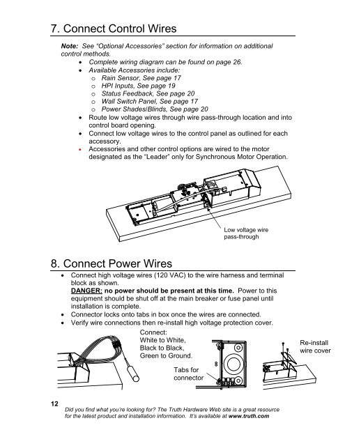
7. Connect Control Wires<br />
Note: See “Optional Accessories” section for information on additional<br />
control methods.<br />
• Complete wiring diagram can be found on page 26.<br />
• Available Accessories include:<br />
o Rain Sensor, See page 17<br />
o HPI Inputs, See page 19<br />
o Status Feedback, See page 20<br />
o Wall Switch Panel, See page 17<br />
o Power Shades/Blinds, See page 20<br />
• Route low voltage wires through wire pass-through location and into<br />
control board opening.<br />
• Connect low voltage wires to the control panel as outlined for each<br />
accessory.<br />
• Accessories and other control options are wired to the motor<br />
designated as the “Leader” only for Synchronous Motor Operation.<br />
Low voltage wire<br />
pass-through<br />
8. Connect Power Wires<br />
• Connect high voltage wires (120 VAC) to the wire harness and terminal<br />
block as shown.<br />
DANGER: no power should be present at this time. Power to this<br />
equipment should be shut off at the main breaker or fuse panel until<br />
installation is complete.<br />
• Connector locks onto tabs in box once the wires are connected.<br />
• Verify wire connections then re-install high voltage protection cover.<br />
Connect:<br />
White to White,<br />
Black to Black,<br />
Green to Ground.<br />
Re-install<br />
wire cover<br />
Tabs for<br />
connector<br />
12<br />
Did you find what you’re looking for? The <strong>Truth</strong> <strong>Hardware</strong> Web site is a great resource<br />
for the latest product and installation information. It’s available at www.truth.com