In-service safety inspection and testing of electrical equipment
In-service safety inspection and testing of electrical equipment
In-service safety inspection and testing of electrical equipment

Create successful ePaper yourself
Turn your PDF publications into a flip-book with our unique Google optimized e-Paper software.
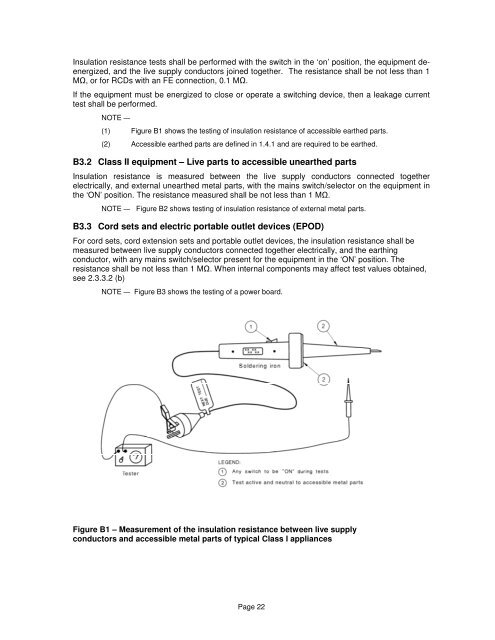
<strong>In</strong>sulation resistance tests shall be performed with the switch in the ‘on’ position, the <strong>equipment</strong> deenergized,<strong>and</strong> the live supply conductors joined together. The resistance shall be not less than 1M, or for RCDs with an FE connection, 0.1 M.If the <strong>equipment</strong> must be energized to close or operate a switching device, then a leakage currenttest shall be performed.NOTE —(1) Figure B1 shows the <strong>testing</strong> <strong>of</strong> insulation resistance <strong>of</strong> accessible earthed parts.(2) Accessible earthed parts are defined in 1.4.1 <strong>and</strong> are required to be earthed.B3.2 Class II <strong>equipment</strong> – Live parts to accessible unearthed parts<strong>In</strong>sulation resistance is measured between the live supply conductors connected together<strong>electrical</strong>ly, <strong>and</strong> external unearthed metal parts, with the mains switch/selector on the <strong>equipment</strong> inthe ‘ON’ position. The resistance measured shall be not less than 1 M.NOTE — Figure B2 shows <strong>testing</strong> <strong>of</strong> insulation resistance <strong>of</strong> external metal parts.B3.3 Cord sets <strong>and</strong> electric portable outlet devices (EPOD)For cord sets, cord extension sets <strong>and</strong> portable outlet devices, the insulation resistance shall bemeasured between live supply conductors connected together <strong>electrical</strong>ly, <strong>and</strong> the earthingconductor, with any mains switch/selector present for the <strong>equipment</strong> in the ‘ON’ position. Theresistance shall be not less than 1 M. When internal components may affect test values obtained,see 2.3.3.2 (b)NOTE — Figure B3 shows the <strong>testing</strong> <strong>of</strong> a power board.Figure B1 – Measurement <strong>of</strong> the insulation resistance between live supplyconductors <strong>and</strong> accessible metal parts <strong>of</strong> typical Class I appliancesPage 22