In-service safety inspection and testing of electrical equipment
In-service safety inspection and testing of electrical equipment
In-service safety inspection and testing of electrical equipment
Create successful ePaper yourself
Turn your PDF publications into a flip-book with our unique Google optimized e-Paper software.
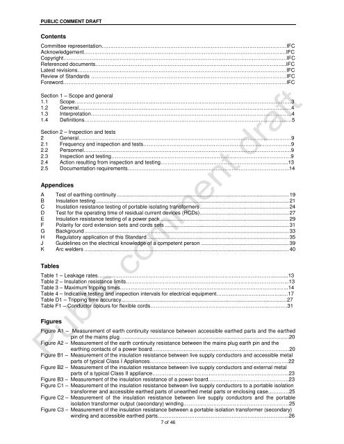
PUBLIC COMMENT DRAFTContentsCommittee representation……………………………………………………………………………………………IFCAcknowledgement…………………………………………………………………………………………………….IFCCopyright……………………………………………………………………………………………………………….IFCReferenced documents……………………………………………………………………………………………....IFCLatest revisions……………………………………………………………………………………………….……….IFCReview <strong>of</strong> St<strong>and</strong>ards …………………………………………………………………………………………………IFCForeword……………………………………………………………………………………………………………….IFCSection 1 – Scope <strong>and</strong> general1.1 Scope……………………………………………………………………………………………………………31.2 General………………………………………………………………………………………………………….41.3 <strong>In</strong>terpretation……………………………………………………………………………………………………41.4 Definitions……………………………………………………………………………………………………….5Section 2 – <strong>In</strong>spection <strong>and</strong> tests2 General………………………………………………………………………………………………………….92.1 Frequency <strong>and</strong> <strong>inspection</strong> <strong>and</strong> tests…………………………………………………………………………92.2 Personnel……………………………………………………………………………………………………….92.3 <strong>In</strong>spection <strong>and</strong> <strong>testing</strong>…………………………………………………………………………………………92.4 Action resulting from <strong>inspection</strong> <strong>and</strong> <strong>testing</strong>……………………………………………………...............132.5 Documentation requirements………………………………………………………………………………..14AppendicesA Test <strong>of</strong> earthing continuity...................................................................................................................... 19B <strong>In</strong>sulation <strong>testing</strong> .................................................................................................................................... 21C <strong>In</strong>uslation resistance <strong>testing</strong> <strong>of</strong> portable isolating transformers............................................................. 24D Test for the operating time <strong>of</strong> residual current devices (RCDs)............................................................. 27E <strong>In</strong>sulation resistance <strong>testing</strong> <strong>of</strong> a power pack ........................................................................................ 29F Polarity for cord extension sets <strong>and</strong> cords sets ..................................................................................... 31G Background............................................................................................................................................ 33H Regulatory application <strong>of</strong> this St<strong>and</strong>ard ................................................................................................. 35J Guidelines on the <strong>electrical</strong> knowledge <strong>of</strong> a competent person ............................................................ 39K Arc welders ............................................................................................................................................ 40TablesTable 1 – Leakage rates………………………………………………………………………………………...........13Table 2 – <strong>In</strong>sulation resistance limits………………………………………………………………………………...13Table 3 – Maximum tripping times…………………………………………………………………………….……..14Table 4 – <strong>In</strong>dicative <strong>testing</strong> <strong>and</strong> <strong>inspection</strong> intervals for <strong>electrical</strong> <strong>equipment</strong>………………………………..…17Table D1 – Tripping time accuracy.................................................................................................................27Table F1 – Conductor colours for flexible cords……………………………………………………….....….…….31FiguresFigure A1 – Measurement <strong>of</strong> earth continuity resistance between accessible earthed parts <strong>and</strong> the earthedpin <strong>of</strong> the mains plug…................................................................................................................20Figure A2 – Measurement <strong>of</strong> the earth continuity resistance between the mains plug earth pin <strong>and</strong> theearthing contacts <strong>of</strong> a power board……………………………………………………………………20Figure B1 – Measurement <strong>of</strong> the insulation resistance between live supply conductors <strong>and</strong> accessible metalparts <strong>of</strong> typical Class I Appliances……………………………………………………………….……22Figure B2 – Measurement <strong>of</strong> the insulation resistance between live supply conductors <strong>and</strong> external metalparts <strong>of</strong> a typical Class II appliance…………………………………………………………………...23Figure B3 – Measurement <strong>of</strong> the insulation resistance <strong>of</strong> a power board……………………………………….23Figure C1 – Measurement <strong>of</strong> the insulation resistance between live supply conductors to a portable isolationtransformer <strong>and</strong> accessible earthed parts <strong>of</strong> unearthed metal parts or enclosing case…………25Figure C2 – Measurement <strong>of</strong> the insulation resistance between live supply conductors <strong>and</strong> the portableisolation transformer output (secondary) winding……………………………………………………25Figure C3 – Measurement <strong>of</strong> the insulation resistance between a portable isolation transformer (secondary)winding <strong>and</strong> accessible earthed parts………………………………………………………………...267 <strong>of</strong> 46


