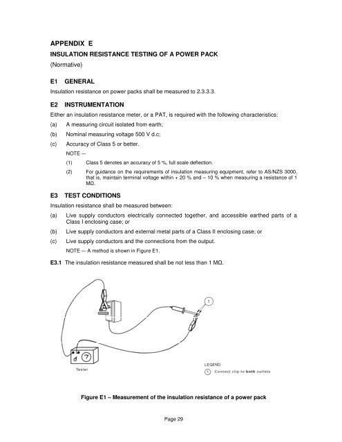
APPENDIX EINSULATION RESISTANCE TESTING OF A POWER PACK(Normative)E1 GENERAL<strong>In</strong>sulation resistance on power packs shall be measured to 2.3.3.3.E2 INSTRUMENTATIONEither an insulation resistance meter, or a PAT, is required with the following characteristics:(a)(b)(c)A measuring circuit isolated from earth;Nominal measuring voltage 500 V d.c;Accuracy <strong>of</strong> Class 5 or better.NOTE —(1) Class 5 denotes an accuracy <strong>of</strong> 5 %, full scale deflection.(2) For guidance on the requirements <strong>of</strong> insulation measuring <strong>equipment</strong>, refer to AS/NZS 3000,that is, maintain terminal voltage within + 20 % <strong>and</strong> – 10 % when measuring a resistance <strong>of</strong> 1M.E3 TEST CONDITIONS<strong>In</strong>sulation resistance shall be measured between:(a)(b)(c)Live supply conductors <strong>electrical</strong>ly connected together, <strong>and</strong> accessible earthed parts <strong>of</strong> aClass I enclosing case; orLive supply conductors <strong>and</strong> external metal parts <strong>of</strong> a Class II enclosing case; orLive supply conductors <strong>and</strong> the connections from the output.NOTE — A method is shown in Figure E1.E3.1 The insulation resistance measured shall be not less than 1 M.Figure E1 – Measurement <strong>of</strong> the insulation resistance <strong>of</strong> a power packPage 29
APPENDIX FPOLARITY FOR CORD EXTENSION SETS AND CORDS SETS(Normative)F1Cord sets <strong>and</strong> cord extension sets with rewireable plugs <strong>and</strong>/or connectors <strong>and</strong>/or cord extensionsockets shall be checked for correct polarity <strong>of</strong> the wiring.F2The correct wiring for a cord set is shown in Figure F1.F3NOTE — A three-conductor cord with a suitable power plug for the locality in which theappliance is used on one end <strong>and</strong> an IEC C13 line socket on the other is commonly calledan 'IEC cord'.The correct wiring for a cord extension set is shown in Figure F2.F4The recommended conductor colours for the flexible cord are given in Table F1 in the “<strong>In</strong>ternational”column. The other two columns are included for completeness, as older cord sets, cord extensionsets, imported cord sets, <strong>and</strong> imported cord extension sets constructed to differing schemes are stillin use. Until confirmed, caution should be exercised, as the active conductor’s insulation may notbe brown.WARNING When imported, plugs on cord sets based on the USA scheme are frequently removed <strong>and</strong>replaced. Such cord sets should be treated with caution until the correct polarity is confirmed.Table F1 – Conductor colours for flexible cordsFunction <strong>In</strong>ternational Superseded USAActive /Line Brown Red BlackNeutral Light Blue Black WhiteEarth Green <strong>and</strong> Yellow Green GreenF5(a)(b)(c)(d)(e)(f)Modern flexible cords conform to the following colour schemes:Single phase, Class II <strong>equipment</strong>: two-core cord with (usually) blue, brown core insulations;Single phase, Class I <strong>equipment</strong>: three-core cord with green-<strong>and</strong>-yellow, blue, brown coreinsulations;Three phase, delta connected or star connected without neutral, Class II appliances: threecorecord with brown, black, grey core insulations;Three phase, delta connected or star connected without neutral, Class I <strong>equipment</strong>: fourcorecable with green-<strong>and</strong>-yellow, brown, black, grey cord insulations;Three phase, star connected with neutral, Class II <strong>equipment</strong>: four-core cord with blue,brown, black, grey core insulations;Three phase, star connected with neutral, Class I <strong>equipment</strong>: five-core cord green-<strong>and</strong>yellow,blue, brown, black, grey core insulations.Page 30