CCR-53S LATCHING - SHORT.indd - Teledyne Coax Switches
CCR-53S LATCHING - SHORT.indd - Teledyne Coax Switches
CCR-53S LATCHING - SHORT.indd - Teledyne Coax Switches

Create successful ePaper yourself
Turn your PDF publications into a flip-book with our unique Google optimized e-Paper software.
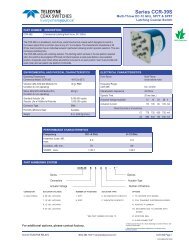
COAX SWITCHESSeries <strong>CCR</strong>-<strong>53S</strong>/CR-<strong>53S</strong>Miniature DC–26.5 GHzLatching SPDT <strong>Coax</strong>ial SwitchGLOSSARYActuatorAn actuator is the electromechanical mechanism thattransfers the RF contacts from one position to another uponDC command.Arc Suppression DiodeA diode is connected in parallel with the coil. This diodelimits the “reverse EMF spike” generated when the coil deenergizesto 0.7 volts. The diode cathode is connected tothe positive side of the coil and the anode is connected tothe negative side.Date CodeAll switches are marked with either a unique serial numberor a date code. Date codes are in accordance with MIL-STD-1285 Paragraph 5.2.5 and consist of four digits.The fi rst two digits defi ne the year and the last two digitsdefi ne the week of the year (YYWW). Thus, 1032 identifi esswitches that passed through fi nal inspection during the32nd week of 2010.LatchingA latching switch remains in the selected position whetheror not voltage is maintained. This can be accomplishedwith either a magnetic or mechanical latching mechanism.IndicatorIndicators tell the system which position the switch is in.Other names for indicators are telemetry contacts or tellbackcircuit. Indicators are usually a set of internally mounted DCcontacts linked to the actuator. They can be wired to digitalinput lines, status lights, or interlocks. Unless otherwisespecifi ed, the maximum indicator contact rating is 30 Vdc,50 mA, or 1.5 Watts into a resistive load.IsolationIsolation is the measure of the power level at the outputconnector of an unconnected RF channel as referenced tothe power at the input connector. It is specifi ed in dB belowthe input power level.Self-CutoffThe self-cutoff option disables the actuator current oncompletion of actuation. Either a series contact (linkedto the actuator) or an IC driver circuit provides the currentcutoff. This option results in minimum power consumptionby the RF switch. Cutthroat is another name used in theindustry for this option. Pulse latching is a term used todescribe a switch without this feature.SPDT SwitchA single-pole double-throw, bi-directional switch that canbe used as having one input and two outputs or two inputsand one output.Switching TimeSwitching time is the total interval beginning with the arrivalof the leading edge of the command pulse at the switch DCinput and ending with the completion of the switch transfer,including contact bounce. It consists of three parts: (1)inductive delay in the coil, (2) transfer time of the physicalmovement of the contacts, and (3) the bounce time of theRF contacts.TTL Switch Driver OptionAs a special option, switch drivers can be provided for bothfailsafe and latching switches, which are compatible withindustry-standard low-power Schottky TTL circuits.Performance Parameters vs FrequencyGenerally speaking, the RF performance of coaxial switchesis frequency dependent. With increasing frequency, VSWRand insertion loss increase while isolation decreases. Alldata sheets specify these three parameters as “worst case”at the highest operating frequency. If the switch is to beused over a narrow frequency band, better performancecan be achieved.Actuator Current vs TemperatureThe resistance of the actuator coil varies as a function oftemperature. There is an inverse relationship between theoperating temperature of the switch and the actuator drivecurrent. For switches operating at 28 VDC, the approximateactuator drive current at temperature, T, can be calculatedusing the equation:I T=Where:I A[1 + .00385 (T-20)]I T= Actuator current at temperature, TI A= Room temperature actuator current –see data sheetT = Temperature of interest in °CMagnetic SensitivityAn electro-mechanical switch can be sensitive to ferrousmaterials and external magnetic fi elds. Neighboring ferrousmaterials should be permitted no closer than 0.5 inches andadjacent external magnetic fi elds should be limited to a fl uxdensity of less than 5 Gauss.SPECIAL FEATURESwitching High-Power or Highly Sensitive SignalsEnsure the most linear response with the best galvanicallymatched contact system in the industry. Extremely lowpassive intermodulation is standard on all of our switches.CarrierFrequency 1CarrierFrequency 2PIM 3rd OrderFrequencyPIM 5thOrder Frequency870 MHz 893 MHz 847 MHz 824 MHzSPDT3rd OrderIntermodulation5th OrderIntermodulation–91 dBm –110 dBm–134 dBc –153 dBc© 2013 TELEDYNE RELAYS (800) 284-7007 • www.teledynecoax.com <strong>CCR</strong>-<strong>53S</strong>/CR-<strong>53S</strong> Page 7<strong>CCR</strong>-<strong>53S</strong>\CR-<strong>53S</strong>\082013\Q3