7955 Cameron Brown Court - Ready Remote
7955 Cameron Brown Court - Ready Remote
7955 Cameron Brown Court - Ready Remote

You also want an ePaper? Increase the reach of your titles
YUMPU automatically turns print PDFs into web optimized ePapers that Google loves.
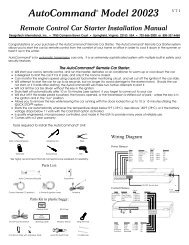
V 8.3pcbv7.3/8.1AutoCommand®“Add-On”<strong>Remote</strong> Control Car StarterModel 20022Installation ManualFor use on automatic vehicles only.For gasoline or diesel vehicles.<strong>7955</strong> <strong>Cameron</strong> <strong>Brown</strong> <strong>Court</strong>Springfield, Virginia 22153 USAwww:designtech-intl.com20022 Page 1
Congratulations on your purchase of the AutoCommand® <strong>Remote</strong> Car Starter. TheAutoCommand® <strong>Remote</strong> Car Starter system allows you to start the car by remotecontrol from the comfort of your home or office in order to cool it down in thesummer or heat it up in the winter.This model 20022 is an “add-on” unit and must be used in conjunction withanother remote control unit such as a remote car alarm or keyless entrysystem.AutoCommand® is for automatic transmission cars only. It is an extremely sophisticatedsystem with multiple built-in safety and security features.The AutoCommand® <strong>Remote</strong> Car Starter:• Will start your car by remote control, and run the heater, defroster, or airconditioner to warm up or cool down the car.• Is designed to start the car if it is in park, and only if the hood is closed.• Can monitor the engine’s speed using a special tachometer monitoring circuit.• Will attempt to start the car for up to six seconds, but no longer (to avoiddamage to the starter motor). Should the car not start, or if it stalls afterstarting, the AutoCommand® will make 2 further attempts to start it.• Will not let the car be driven without the key in the ignition.• Shuts itself off automatically after 10 or 15 minutes (user selectable) if youforget to come out to your car.• Will shut off if the brake pedal is pushed, the hood is opened, or the transmissionis shifted out of park - unless the key is in the ignition and in the“run” position.• Allows you to remove the key while leaving the car running with the doorslocked for up to 10 or 15 minutes utilizing the QUICK STOP TM option.• Starts the car automatically should the temperature drop below 0°F (-18’C),or if the battery voltage drops below 11 volts with the VACATION TM option.• Is quality engineered, microprocessor controlled, and made in the USA toprovide many years of reliable use.Page 2 20022LIMITED WARRANTYDesignTech International, Inc. Warrants to the original consumer/purchaser that this productshall be free of defects in material and workmanship under normal use and circumstances for aperiod of two (2) years from the date of original purchase for use. When the originalconsumer/purchaser returns the product to DesignTech International Inc., <strong>7955</strong> <strong>Cameron</strong> <strong>Brown</strong><strong>Court</strong>, Springfield, Virginia 22153, USA within the warranty period, and if the product isdefective DesignTech International, Inc. will at its option repair or replace such.This warranty shall constitute the sole liability of DesignTech International, Inc. concerningthe product. DesignTech International, Inc. expressly disclaims all other warranties INCLUD-ING, WITHOUT LIMITATION, THE WARRANTIES OF MERCHANT ABILITY AND FIT-NESS FOR A PARTICULAR PURPOSE. NO PERSON, FIRM , OR CORPORATION IS AU-THORIZED TO ASSUME FOR DESIGNTECH INTERNATIONAL, INC. ANY OTHER LI-ABILITY IN CONNECTION WITH THE SALE AND USE OF THE PRODUCT. DesignTechInternational, Inc. and agents and distributors will bear no liability whatsoever for incidental orconsequential damages or charges of any kind.Some states do not allow the exclusion or limitation of incidental or consequential damages, sothe above disclaimer regarding incidental or consequential damages may not apply to you.This warranty shall be effective only if the registration card is fully completed and mailed withproof of purchase to: DesignTech International, Inc., <strong>7955</strong> <strong>Cameron</strong> <strong>Brown</strong> <strong>Court</strong>, Springfield,Virginia 22153, USA within ten (10) days after date of purchase.This warranty is void if the product or has been damaged or tampered with or if the product orany such parts have been opened. In all cases of damage during shipment, a claim must be filedwith the shipping carrier and not with DesignTech International, Inc.This warranty gives you specific legal rights; you may also have other rights which vary fromstate to state.OUT OF WARRANTY REPAIRSDesignTech International, Inc. will at its option either (1) replace this product with a functionallysimilar (but not necessarily visually identical) refurbished product or (2) repair the originalproduct and return it to the original consumer/purchaser C.O.D. covering all reasonable repair orreplacement charges if the product is returned prepaid to DesignTech International, Inc., <strong>7955</strong><strong>Cameron</strong> <strong>Brown</strong> <strong>Court</strong>, Springfield, VIRGINIA 22153, USA, after the two year warranty periodhas expired.__________________________________________________________________________This registration card must be returned within ten (10) days of purchase.NAME_________________________________________________________ User's Age______________ADDRESS_________________________________________________________________________________________________________________________________________________________________City State ZipPLACE OF PURCHASE_____________________________________DATE OF PURHASE____________Product Purchased: AutoCommand #20022Purchased for : ________YOURSELF _________SPOUSE________OTHER FAMILY MEMBER _________FRIENDWhere did you learn about this product?____________________________________________Vehicle Make:__________________Vehicle Model:________________Year:_________________________Please send me FREE information on other innovative DesignTech products.DesignTech International, Inc.<strong>7955</strong> <strong>Cameron</strong> <strong>Brown</strong> <strong>Court</strong>, Springfield, Virginia 22153, USATel: (703) 866-2000 Fax: (703)866-2001v8.320022 Page 19
Important Note:Make sure that all drivers who will be operating the AutoCommand® are fullyaware of the safety precautions installed and their limitations. Stress the importanceof switching the On/Off control switch to the “OFF” position (down)every time the car is serviced. Show the user how the control switch must beturned off and on again after pulling out the key before leaving the car. Give theuser a copy of the tan colored page - USER TIPS AND NOTES so that they canfamiliarize themselves with the product.!! WARNING !!Do not connect this AutoCommand® to a manual transmission vehicle.Doing so could cause serious property damage, personal injury, and willvoid all warranties.Tools required to install the AutoCommand® unit:USER INFORMATION:The brown USER TIPS & NOTES sheet gives you further detail regardingdaily use of this product. Any modifications not expressly approved by Design-Tech will void the user’s authority to operate the equipment.Wire cutters/strippersPliersSoldering ironScrewdriversOTHER ACCESSORIESThe following installation accessories are available through your dealer or Design-Tech. All prices are in US dollars. Shipping and handling costs are included.#20041 VATS kit $14.95(to work with the GM PASS key system)#20043 Bosch 30 amp relays $9.95#20049 Wire harness for above relay $9.95Please have model number and diagnostic code readybefore calling tech supportTest meterDrill and 1/2” bitWe highly recommend that all connections be soldered for reliability.Parts listAutoCommand® moduleBaggie of PartsControl harness (10 position)6 Power & Ignition wiresParts kit in plastic baggy:30 A Fuse 3 Tab connectorsOn/Off control switchWarning Label<strong>7955</strong> <strong>Cameron</strong> <strong>Brown</strong> Ct; Springfield, Virginia 22153 USATel: (703)866-2000 or (800)337-4468www:designtech-intl.comWindow decalHood pin switch setRing terminal2 cable ties (not pictured)Page 18 2002220022 Page 3
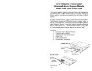
AutoCommand Model 20022Color Function Type RequiredPink Power(+12V) Input YesWhite Accessory/Lights Relay output YesYellow Starter Relay output YesBlue Ignition 1 Relay output YesGreen Ignition 2 Relay output MaybeBlack Ground Input Yes1. Remove the top and bottom halves of the steering column shroud.2. Locate the small three wire harness (with White, Black and Yellow wires) running down from theignition key cylinder on the top right hand side of the steering column into the instrument panel.3. Cut the Yellow wire in half and bare back the Black wire.4. With the ignition key in and turned to the “ON” or “RUN” position, measure the resistance betweenthe key side of the Yellow wire and the Black wire. Make several measurements to verifythat you have a consistent resistance. You also need to change your test leads around. You will findthat you get two different readings. So far we have found that the higher of the two readings is thecorrect resistance.5. When you have correctly identified the correct resistance obtain a resistance of the same value.6. Locate the Black “Bulb Test” wire on the left side of the steering column in cavity “D” or “E” ofthe Black 5-way connector, just above the main ignition switch connector.7. Wire the relay as shown in the following Diagram.Color Function Type RequiredYellow/Green Alarm Control (+) 400 mA NoGreen/White Sensor IN Relay No<strong>Brown</strong> Accessory Pulse (-) 400 mA No<strong>Brown</strong>/White Alarm Disable (-) 400mA NoGray/Black Sensor OUT Relay NoLeft White ButtonRight Red Button4) New GM PASSLOCK ® II Anti-Theft System for 1998 modelvehicles. In 1997 the Malibu/Cutlass and then in 1998 all truck platforms (Full sizePickup, Suburban, S-10/Sonoma, Blazer/Jimmy, Tahoe/Yukon and Astro/Safari) came outwith this new Passlock II system.LEDPlug-in Control SwitchColor Function Type RequiredRed/Black Control Switch YesRed/White <strong>Remote</strong> - Input YesGreen Tach Input NoViolet Hood - Input YesOrange Brake + Input YesPage 4 20022Use the diagram above and the list below to interface to this new type system. Note that theYellow wire for the Passlock is a similar gauge wire to the Starter wire. Don’t confuse these.You must acquire a resistor value within 5% of the value of the resistor in the key. Additionally,there is No BULB TEST wire on this system, so pin 87 is not used.Substitute as follows:Wire color above Trucks Malibu / Clutlass‘Black or Yellow’ Yellow Yellow‘Black’ Orange/Black Black‘Black/White or White’ Red/White Red/White20022 Page 17
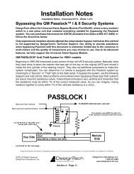
Most of the 1990-1995 Cadillacs have a slight variation on the wiring for the VATSsystem. On these cars, there is an ORANGE wire (actually a vinyl sleeve) that containssmaller wires. This is located underneath the steering column next to the YELLOWsleeve that is labeled “Air bag wiring” -- do not cut this Yellow sleeve. Slit the ORANGEsleeve open to expose two pairs of wires which are either both white, OR both yellow,OR both black.!! WARNING !!On cars with airbags, you may notice bright yellow tubes or harnesses underneaththe steering column area. DO NOT tamper with these wires in any way,so as to prevent personal injury and/or damage to the air bag system.Note:When installing a GM vehicle with a VATS bypass system, the GREENIGN 2 wire must only go to the VATS relay. If you need IGN2 in the car,simply supply power to the IGN2 wire of the vehicle by jumping power fromthe BLUE IGN1 wire. (Thus BLUE will be powering up 2 wires behind thekey -- and in some cases 3 wires).Battery gases are explosive. Do not smoke while working near the car’s battery.!!CAUTION!!2) Diesel Vehicles: You must hook the RED/BLACK wire up to the dieselglow-plug light wire or to the positive side of the vlow plugs itself as described inSTEP 18.The following chart outlines the options that need to be set for diesel vehicles. (Usethe Chrysler settings for all other diesel vehicles.)Option 3 4 5 6Ext. Crank Super Crank IgnoreMeter DieselChrysler X XFord X X XChevrolet X X X X3) General Motors Passlock Security System BypassNew GM PASSLOCK ® Anti-Theft System for 1995 through 1997 modelsBeginning in 1995 and 1996 GM introduced a new version of their old VATSsecurity system. This new PASSLOCK ® system will only be found in the 1995Chevrolet Z24 Cavalier, Pontiac Sunfire GT only, 1996+ Pontiac Grand Am,Oldsmobile Achieva, and the Buick Skylark, Chevrolet Cavalier and PontiacSunfire. You can determine if the vehicle is equipped with this system bychecking for a “Security” or “Theft” light on the dash panel. Basically, whatthey have done is taken the resistor that was part of the key on the originalVATS and moved it to inside the lock cylinder of the steering column. Theyhave also set additional parameters to make this even more complicated. Tobypass this system, use the following diagram and instructions. Follow theseinstructions very carefully and remember that the resistance must be within 5%of the correct measured value.When working the wires through the car’s firewall, be sure to protect themfrom sharp metal edges and from hot surfaces on the engine.Note: Some installers connect a battery charger to the vehicle’s battery duringinstallation. This is fine, but it must be removed before running the vehicleunder AutoCommand® control.INSTALLATION INSTRUCTIONS1. Before You StartTake the time to read through the whole installation manual.Wire Harnesses: Before installation, always check that your wireharness matches the list/drawing on page 4 of the manual.IMPORTANT: After having read the entire manual, start theinstallation by putting the yellow WARNING STICKER in the engine compartment.Choose a surface that is clean and readily visible when the hood isopen.Note that for these vehicles with PASSLOCK, the AutoCommand’s Green Ignition2 wire goes to the vehicle’s White Ignition wire. The AutoCommand’sWhite Accessory wire goes to the Vehicle’s Orange Ignition wire.Page 16 2002220022 Page 5
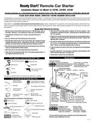
POWER & IGNITION WIRESThe AutoCommand® module will be installed under the dash once all wiringhas been completed. Do not mount the module at this time! You will needto check the diagnostic light (LED) as the installation progresses. Locate(or drill) a hole in the firewall to run the VIOLET (hood) and the GREEN(tach) wires of the Control Harness and the PINK wire of the Power Harnessthrough into the engine compartment. The remaining short wires stay in thepassenger area. Leave about a foot of the wire harness under the dash for easeof working and visual access to the diagnostic lights.Note:Always connect the Black and Pink wires before connectingany of the other wires.)2. Black Wire (14 AWG) GroundConnect this BLACK wire to a very good, clean chassis ground in the driver’skick panel area. Use the small red ring terminal if needed. The metal bracingaround or beneath the dash board is not adequate.3. Pink Wire (12 AWG) Power (+12V)Plug this wire onto the spade terminal marked Power. Run the other endof this wire through the firewall of your vehicle and to the positive side ofthe vehicle’s battery terminal. Connect the ring terminal of the fuseholder provided to the vehicle’s positive battery post. Join the remainingends of the power wire together by soldering them. Alternatively, youmay wish to use a Yellow butt terminal, but we recommend soldering.Ignition Key Diagram for Steps 4-7The vehicle’s wires are found coming off of the key switch.C. You can choose the next option by pushing the left button again toindex to the next option. When you get to the next option youwant to change, simply repeat Step B above. After six seconds,the AutoCommand® automatically exits the programming mode(Three LED flashes).D. Turn the Control Switch back ON and confirm that the LED flashesonce as the switch is turned ON.SPECIAL CASES1) VATS system (for GM cars with special PASS key).If you have a GM vehicle with a factory anti-theft system (a resistor in the key),you need to follow these directions:Measure the resistance of the key. It should be between 392 ohms and 11,800ohms. To do this, put the ohm meter probes on each side of the key pellet.This value should be close to one of the following (all values in ohms): 392,523, 681, 887, 1.13K, 1.47K, 1.87K, 3.01K, 3.74K, 4.75K, 6.04K, 7.5K, 9.53K,11.8K. Purchase a resistor with a value within 5% of this measured value and a30 amp BOSCH type relay.Locate the pair of VATS wires (sometimes White/Black striped and Purple/Black striped) running behind the dash from the passenger side to the driver’sside behind the key switch. Connect our Ignition 2 (GREEN) wire to pin 86and ground to pin 85 on the relay. NOTE: You will have to use IGN 1 to powerup all of the Ignition wires behind the key -- since IGN 2 needs to be used herefor the VATS relay. Cut ONE of the VATS wires and connect the key-switchside to NC pin 87A, and the other side (Engine Side) to common pin 30. Connectthe other VATS wire to NO pin 87 with the selected resistor soldered in line asshown here:Lock/OffACCACCRUNSTARTPage 6 2002220022 Page 15
Control Harness (All wires are the smaller 18 AWG size)9. Violet Wire Hood Pin Switch Control HarnessThe hood pin switch MUST be installed with the AutoCommand®. Itprevents operation of the AutoCommand® when the hood is open. Connectthe VIOLET wire to the hood pin switchusing the red connector.Note:If you already have a hoodpin switch which is beingused by a car alarm system,you may share thewiring -- but be sureto diode isolate eachwire going to thehood pin switchwith the bandsof diodespointing towardsthepin switchas follows:10. Orange Wire Brake Shut-off Control HarnessThe ORANGE 18 gauge wire will disable the AutoCommand® when the brakepedal is pressed down. This is an added anti-theft safety feature. This connectionis usually made under or behind the brake pedal linkage at the switch.Connect the ORANGE to the wire that receives +12 volt only when the brakepedal is pressed down. Any +12 volt input on this wire will shut off the Auto-Command®. In some cars, the ignition must be on to see the power at the brakewire. This wire must be hooked up. This is a critical safety feature. This hookupis also required for other options discussed later.20. Trouble Shooting with the Self DiagnosticsThe AutoCommand® contains a built in diagnostic routine that will indicatewhy the unit turned off the car the last time that the unit was used. To activatethe diagnostic mode, simply turn the On/Off control switch to the “OFF”position. In a few seconds, the red LED on the module will flash 1 to 6 timesto identify the problem. See the chart below for an explanation of the flashes:1 flash 10/15 minute time out -- unit should be fine.2 flashes Brake or Hood activated3 flashes No Tach or Stalled. Check tach learning. Or confirm that thealternator is being powered up by one of the ignition wires.4 flashes Received another remote input signal.5 flashes Transmission was shifted into gear.6 flashes Low battery voltage, or may be missing an ignition wirewhich powers up the alternator8 flashes Over-current. A transistor output is being over driven.12 flashes The control switch was turned off.In order to get an accurate diagnostic, allow the unit to go through its completestarting cycle(s). The unit may only try to start once or it may try 3 times. Inorder to get an accurate reading, please wait 45 seconds after its last attempt tostart.21. Special Programming OptionsThe AutoCommand® unit has 8 special options and features. You will notneed to use these special options in most situations. The factory settings willoperate most vehicles. You must turn the On/Off control switch to the “OFF”position to program any features. Note that when turning off this controlswitch, the red LED will flash a few times, giving the diagnostic code describedin Section 20. Wait a few seconds for it to finish before programming your newOptions.# Factory Setting (2 flashes) Option (1 flash)1 “No-Tach” Tach Mode2 10 min. run time 15 min. run time3 Normal Crank Extended Crank4 Normal Crank Super Crank5 Normal Voltage Metering Ignore Voltage Metering6 Gasoline vehicles Diesel vehicles7 “Enable” feature No “Enable”8 Normal Trigger Double Pulse TriggerPage 8 2002220022 Page 13
16. <strong>Brown</strong> Wire Acc. Pulse Control HarnessThe optional BROWN wire is the Accessory Pulse output which gives out a 1 secondtransistor ground output just as the Accessory wire comes on. This is important insome vehicles to control the defroster or to control the GM R.A.P. system. Again, thisis a 400 mA transistor ground output which MUST drive a relay (not included).17. <strong>Brown</strong>/White Alarm Disable Control HarnessThe optional BROWN/WHITE wire will put out a 1 second negative pulse justbefore starting the vehicle. This wire can be used to turn off the factory alarmsystem in vehicles that have them.Note:On most vehicles, this wire can be connected directly to thefactory alarm/disarm wire which is usually located in the driver'skick panel.18. Red/Black Diesel Input Control HarnessThe optional RED/BLACK wire will sense the turning on and off of the DieselGlow-Plug light to determine when to crank the vehicle. Hook this wire to theswitched wire of the diesel glow-plug light or to the glow-plug wire itself.Required Final Steps19. Trying the Unit OutWARNING: Be prepared to apply the brake during this testing. Close thehood, fully apply the emergency brake, and place the vehicle in Park.A. Once all the wiring is checked and is correct, put the car inpark, then press the button on the transmitter of the host alarmor keyless entry system which controls the AutoCommand.B. The car should start and continue to run for ten minutes.Please make sure that the engine shuts down if the car is takenout of park, the hood is opened or the brake is pressed.Page 12 2002211. Initializing the AutoCommand®BEFORE THE CAR WILL START FOR THE FIRST TIME, YOU MUST INITIALIZE THEAUTOCOMMANDA. The AutoCommand® requires the installer to press and hold thebrake pedal and open Hood.B. While depressing the brake (with the engine off) turn the ignitionkey to the “RUN” (not “start”) position.C. Put the car in gear from the “PARK” position.D. Put the car back in “PARK” and release the brake.Confirm initialization by turning the ON/OFF control switch “OFF” and then“ON”. The red LED on the AutoCommand® module will flash once immediatelyas the switch is flipped from the “OFF” to the “ON” position.IF THE UNIT DOES NOT INITIALIZE AT THIS TIME, REPEAT STEPSA THROUGH D ABOVE.12. Green Wire Tach Input Control HarnessThe AutoCommand® has two ways of monitoring the car during the startingprocess. Both ways will ensure a clean, accurate start. Read about both methodsbefore deciding which one to use. Normally you should try the “No Tach TM ”method first.“No Tach TM ” StartingThis starting method does not require the connection of the GREEN tachwire. This method will start the car by reading the car’s voltage before attemptingto start, and then looking for a voltage increase when the alternatorkicks in. This feature automatically takes into account voltage, temperature,and the time since the vehicle was last run. The “No-Tach TM” starting ispreset at the factory and you can skip step 12A if you would like to use it.Note that if the vehicle is hard to start, set option #3 (page 14) for “extendedcrank.”Tachometer sensingIf the vehicle is generally hard starting (requiring a cranking time of morethan 1 second) you will get more accurate starting with the tachometer sensingstarting method. This method starts the car by reading the engine speed(tach) information from a wire under the hood. If you choose tachometer sensing,connect the GREEN (18 awg) wire to the car’s tach wire under the hood.After you have connected the GREEN wire, you need to teach the AutoCommand®the vehicle’s tach rate. Proceed to step 12A.Note: You must have already initialized the vehicle.20022 Page 9
12A. Tach Rate LearningNote: Only use if the tachometer sensing method is chosen.A. Connect the GREEN wire to the car’s tach wire under the hood.B. Turn the On/Off control switch to the “OFF” position. Wait 5 secondsfor the flashing of the red LED to stop.C. Push the white button to the left of the red LED once and you will see thered LED flash. Now push the red button on the right side for a seconduntil you see the red LED flash again. You are now in TACH mode. (Ifthe LED flashed twice -- simply push the right button again until you getonly one flash).D. Wait 5 seconds for the red LED to flash 3 times.E. Turn the On/Off control switch back to the “ON” positionF. Start the car and let it get to a normal idle. Do not press on the gaspedal.G. Push the red button to the right of the red LED.H. Watch the red LED. It will turn on (solidly) after 3 or 4 seconds,indicating that the idle rate has been learned.I. Turn the key to the “Lock/Off” position.Note: Once this step is complete, the red LED should remain lit only when the engineis running (at up to twice the learned idle rate--above this rate the LED lightshould shut off). THIS IS CRITICAL. Confirm this by running the engine(with the key in the ignition) and pressing the gas pedal to raise the idle rate totwice the normal rate. The red LED should turn off. If it does not turn off,repeat the tach rate learning step and check the GREEN wire connection andlocation.13. Red/White Wire <strong>Remote</strong> Input Control HarnessThe RED/WHITE wire is used to trigger the AutoCommand® to start. Giving thiswire a negative pulse will cause the AutoCommand® to start. Giving it another negativepulse will cause it to stop.Hook this wire up to the output wire of your remote car alarm or keyless entry system.Or, hook it to the lock or unlock wire of your vehicle and set Option 8 as described inSection 21.This input wire can also be triggered by our optional Smart Car Pager accessory whichcan be controlled from any telephone anywhere in the world. This option requires thepager module, an activation fee of $25 and a monthly service fee of $3.00/mo.OPTIONAL STEPSMany of the optional steps require a relay to be hooked up. The most common relayused for this type of application is the Bosch type automotive relay P/N 0332209150. Use the diagrams below for a typical hookup. If you use another type ofrelay, then you need to know that pins 85 and 86 in this diagram represent the coilsof the relay. Pin 30 is the common and pin 87 is the normally open contact. If yourrelay has a pin 87A, then it is not used for these applications. The diagrams below aretypically used for applications such as headlamp or parking lamp connections.14.Yellow/Green Alarm ControlControl HarnThe YELLOW/GREEN wire is specifically designed to control the Ignition Inputof the remote control alarm system which is triggering the AutoCommand. Connectthis YELLOW/GREEN wire directly to the Ignition Input of the alarm. ThisYELLOW/GREEN wire will go to +12 volts anytime it sees +12 volts on theAutoCommand’s BLUE IGN 1 wire from the key. Thus this output follows the IGN1 status. The only exception is that when the AutoCommand is powering up thevehicle this wire will not activate. Thus the alarm remains operational duringAutoCommand control -- but not otherwise when the key alone is controlling theigntion. This is a 300 mA transistor positive output.15. GREEN/WHITE Sensor Loop IN Control HarnGRAY/BLACK Sensor Loop OUT Control HarnThis GREEN/WHITE wire is the input to a normally closed relay. When the Auto-Command is running -- this relay opens. Thus if you have an external sensor such asa shock sensor -- you can pass this sensor’s output through the AutoCommand.When the AutoCommand is running -- this sensor is opened -- or bypassed.Cut the sensor output wire in half. Connect one side to this GREEN/WHITE wireand the other side of the cut sensor wire to the GRAY/BLACK wire.Page 10 2002220022 Page 11